EP2712998A2 - Bewegungsvorrichtung für ein bewegbares Möbelteil - Google Patents
Bewegungsvorrichtung für ein bewegbares Möbelteil Download PDFInfo
- Publication number
- EP2712998A2 EP2712998A2 EP13004634.5A EP13004634A EP2712998A2 EP 2712998 A2 EP2712998 A2 EP 2712998A2 EP 13004634 A EP13004634 A EP 13004634A EP 2712998 A2 EP2712998 A2 EP 2712998A2
- Authority
- EP
- European Patent Office
- Prior art keywords
- output
- actuator
- movement
- coupling
- gear
- Prior art date
- Legal status (The legal status is an assumption and is not a legal conclusion. Google has not performed a legal analysis and makes no representation as to the accuracy of the status listed.)
- Granted
Links
Images

Classifications
-
- E—FIXED CONSTRUCTIONS
- E05—LOCKS; KEYS; WINDOW OR DOOR FITTINGS; SAFES
- E05F—DEVICES FOR MOVING WINGS INTO OPEN OR CLOSED POSITION; CHECKS FOR WINGS; WING FITTINGS NOT OTHERWISE PROVIDED FOR, CONCERNED WITH THE FUNCTIONING OF THE WING
- E05F15/00—Power-operated mechanisms for wings
- E05F15/60—Power-operated mechanisms for wings using electrical actuators
- E05F15/603—Power-operated mechanisms for wings using electrical actuators using rotary electromotors
-
- E—FIXED CONSTRUCTIONS
- E05—LOCKS; KEYS; WINDOW OR DOOR FITTINGS; SAFES
- E05Y—INDEXING SCHEME ASSOCIATED WITH SUBCLASSES E05D AND E05F, RELATING TO CONSTRUCTION ELEMENTS, ELECTRIC CONTROL, POWER SUPPLY, POWER SIGNAL OR TRANSMISSION, USER INTERFACES, MOUNTING OR COUPLING, DETAILS, ACCESSORIES, AUXILIARY OPERATIONS NOT OTHERWISE PROVIDED FOR, APPLICATION THEREOF
- E05Y2201/00—Constructional elements; Accessories therefor
- E05Y2201/20—Brakes; Disengaging means; Holders; Stops; Valves; Accessories therefor
- E05Y2201/214—Disengaging means
- E05Y2201/216—Clutches
-
- E—FIXED CONSTRUCTIONS
- E05—LOCKS; KEYS; WINDOW OR DOOR FITTINGS; SAFES
- E05Y—INDEXING SCHEME ASSOCIATED WITH SUBCLASSES E05D AND E05F, RELATING TO CONSTRUCTION ELEMENTS, ELECTRIC CONTROL, POWER SUPPLY, POWER SIGNAL OR TRANSMISSION, USER INTERFACES, MOUNTING OR COUPLING, DETAILS, ACCESSORIES, AUXILIARY OPERATIONS NOT OTHERWISE PROVIDED FOR, APPLICATION THEREOF
- E05Y2201/00—Constructional elements; Accessories therefor
- E05Y2201/20—Brakes; Disengaging means; Holders; Stops; Valves; Accessories therefor
- E05Y2201/23—Actuation thereof
- E05Y2201/232—Actuation thereof by automatically acting means
- E05Y2201/234—Actuation thereof by automatically acting means direction dependent
-
- E—FIXED CONSTRUCTIONS
- E05—LOCKS; KEYS; WINDOW OR DOOR FITTINGS; SAFES
- E05Y—INDEXING SCHEME ASSOCIATED WITH SUBCLASSES E05D AND E05F, RELATING TO CONSTRUCTION ELEMENTS, ELECTRIC CONTROL, POWER SUPPLY, POWER SIGNAL OR TRANSMISSION, USER INTERFACES, MOUNTING OR COUPLING, DETAILS, ACCESSORIES, AUXILIARY OPERATIONS NOT OTHERWISE PROVIDED FOR, APPLICATION THEREOF
- E05Y2201/00—Constructional elements; Accessories therefor
- E05Y2201/20—Brakes; Disengaging means; Holders; Stops; Valves; Accessories therefor
- E05Y2201/23—Actuation thereof
- E05Y2201/232—Actuation thereof by automatically acting means
- E05Y2201/236—Actuation thereof by automatically acting means using force or torque
- E05Y2201/238—Actuation thereof by automatically acting means using force or torque reaction force or torque
-
- E—FIXED CONSTRUCTIONS
- E05—LOCKS; KEYS; WINDOW OR DOOR FITTINGS; SAFES
- E05Y—INDEXING SCHEME ASSOCIATED WITH SUBCLASSES E05D AND E05F, RELATING TO CONSTRUCTION ELEMENTS, ELECTRIC CONTROL, POWER SUPPLY, POWER SIGNAL OR TRANSMISSION, USER INTERFACES, MOUNTING OR COUPLING, DETAILS, ACCESSORIES, AUXILIARY OPERATIONS NOT OTHERWISE PROVIDED FOR, APPLICATION THEREOF
- E05Y2201/00—Constructional elements; Accessories therefor
- E05Y2201/20—Brakes; Disengaging means; Holders; Stops; Valves; Accessories therefor
- E05Y2201/23—Actuation thereof
- E05Y2201/246—Actuation thereof by auxiliary motors, magnets, springs or weights
-
- E—FIXED CONSTRUCTIONS
- E05—LOCKS; KEYS; WINDOW OR DOOR FITTINGS; SAFES
- E05Y—INDEXING SCHEME ASSOCIATED WITH SUBCLASSES E05D AND E05F, RELATING TO CONSTRUCTION ELEMENTS, ELECTRIC CONTROL, POWER SUPPLY, POWER SIGNAL OR TRANSMISSION, USER INTERFACES, MOUNTING OR COUPLING, DETAILS, ACCESSORIES, AUXILIARY OPERATIONS NOT OTHERWISE PROVIDED FOR, APPLICATION THEREOF
- E05Y2201/00—Constructional elements; Accessories therefor
- E05Y2201/60—Suspension or transmission members; Accessories therefor
- E05Y2201/622—Suspension or transmission members elements
- E05Y2201/696—Screw mechanisms
- E05Y2201/704—Worm wheels
-
- E—FIXED CONSTRUCTIONS
- E05—LOCKS; KEYS; WINDOW OR DOOR FITTINGS; SAFES
- E05Y—INDEXING SCHEME ASSOCIATED WITH SUBCLASSES E05D AND E05F, RELATING TO CONSTRUCTION ELEMENTS, ELECTRIC CONTROL, POWER SUPPLY, POWER SIGNAL OR TRANSMISSION, USER INTERFACES, MOUNTING OR COUPLING, DETAILS, ACCESSORIES, AUXILIARY OPERATIONS NOT OTHERWISE PROVIDED FOR, APPLICATION THEREOF
- E05Y2201/00—Constructional elements; Accessories therefor
- E05Y2201/60—Suspension or transmission members; Accessories therefor
- E05Y2201/622—Suspension or transmission members elements
- E05Y2201/71—Toothed gearing
-
- E—FIXED CONSTRUCTIONS
- E05—LOCKS; KEYS; WINDOW OR DOOR FITTINGS; SAFES
- E05Y—INDEXING SCHEME ASSOCIATED WITH SUBCLASSES E05D AND E05F, RELATING TO CONSTRUCTION ELEMENTS, ELECTRIC CONTROL, POWER SUPPLY, POWER SIGNAL OR TRANSMISSION, USER INTERFACES, MOUNTING OR COUPLING, DETAILS, ACCESSORIES, AUXILIARY OPERATIONS NOT OTHERWISE PROVIDED FOR, APPLICATION THEREOF
- E05Y2400/00—Electronic control; Electrical power; Power supply; Power or signal transmission; User interfaces
- E05Y2400/10—Electronic control
- E05Y2400/32—Position control, detection or monitoring
- E05Y2400/322—Position control, detection or monitoring by using absolute position sensors
-
- E—FIXED CONSTRUCTIONS
- E05—LOCKS; KEYS; WINDOW OR DOOR FITTINGS; SAFES
- E05Y—INDEXING SCHEME ASSOCIATED WITH SUBCLASSES E05D AND E05F, RELATING TO CONSTRUCTION ELEMENTS, ELECTRIC CONTROL, POWER SUPPLY, POWER SIGNAL OR TRANSMISSION, USER INTERFACES, MOUNTING OR COUPLING, DETAILS, ACCESSORIES, AUXILIARY OPERATIONS NOT OTHERWISE PROVIDED FOR, APPLICATION THEREOF
- E05Y2400/00—Electronic control; Electrical power; Power supply; Power or signal transmission; User interfaces
- E05Y2400/10—Electronic control
- E05Y2400/32—Position control, detection or monitoring
- E05Y2400/35—Position control, detection or monitoring related to specific positions
- E05Y2400/354—End positions
-
- E—FIXED CONSTRUCTIONS
- E05—LOCKS; KEYS; WINDOW OR DOOR FITTINGS; SAFES
- E05Y—INDEXING SCHEME ASSOCIATED WITH SUBCLASSES E05D AND E05F, RELATING TO CONSTRUCTION ELEMENTS, ELECTRIC CONTROL, POWER SUPPLY, POWER SIGNAL OR TRANSMISSION, USER INTERFACES, MOUNTING OR COUPLING, DETAILS, ACCESSORIES, AUXILIARY OPERATIONS NOT OTHERWISE PROVIDED FOR, APPLICATION THEREOF
- E05Y2400/00—Electronic control; Electrical power; Power supply; Power or signal transmission; User interfaces
- E05Y2400/10—Electronic control
- E05Y2400/36—Speed control, detection or monitoring
-
- E—FIXED CONSTRUCTIONS
- E05—LOCKS; KEYS; WINDOW OR DOOR FITTINGS; SAFES
- E05Y—INDEXING SCHEME ASSOCIATED WITH SUBCLASSES E05D AND E05F, RELATING TO CONSTRUCTION ELEMENTS, ELECTRIC CONTROL, POWER SUPPLY, POWER SIGNAL OR TRANSMISSION, USER INTERFACES, MOUNTING OR COUPLING, DETAILS, ACCESSORIES, AUXILIARY OPERATIONS NOT OTHERWISE PROVIDED FOR, APPLICATION THEREOF
- E05Y2400/00—Electronic control; Electrical power; Power supply; Power or signal transmission; User interfaces
- E05Y2400/10—Electronic control
- E05Y2400/36—Speed control, detection or monitoring
- E05Y2400/37—Speed control, detection or monitoring by using acceleration sensors
-
- E—FIXED CONSTRUCTIONS
- E05—LOCKS; KEYS; WINDOW OR DOOR FITTINGS; SAFES
- E05Y—INDEXING SCHEME ASSOCIATED WITH SUBCLASSES E05D AND E05F, RELATING TO CONSTRUCTION ELEMENTS, ELECTRIC CONTROL, POWER SUPPLY, POWER SIGNAL OR TRANSMISSION, USER INTERFACES, MOUNTING OR COUPLING, DETAILS, ACCESSORIES, AUXILIARY OPERATIONS NOT OTHERWISE PROVIDED FOR, APPLICATION THEREOF
- E05Y2600/00—Mounting or coupling arrangements for elements provided for in this subclass
- E05Y2600/40—Mounting location; Visibility of the elements
- E05Y2600/458—Mounting location; Visibility of the elements in or on a transmission member
-
- E—FIXED CONSTRUCTIONS
- E05—LOCKS; KEYS; WINDOW OR DOOR FITTINGS; SAFES
- E05Y—INDEXING SCHEME ASSOCIATED WITH SUBCLASSES E05D AND E05F, RELATING TO CONSTRUCTION ELEMENTS, ELECTRIC CONTROL, POWER SUPPLY, POWER SIGNAL OR TRANSMISSION, USER INTERFACES, MOUNTING OR COUPLING, DETAILS, ACCESSORIES, AUXILIARY OPERATIONS NOT OTHERWISE PROVIDED FOR, APPLICATION THEREOF
- E05Y2900/00—Application of doors, windows, wings or fittings thereof
- E05Y2900/20—Application of doors, windows, wings or fittings thereof for furniture, e.g. cabinets
Definitions
- the invention relates to a movement device for a movable furniture part, in particular furniture flap, door or drawer or the like, with an actuator and a drivable by the actuator output for the movable furniture part, which has at least one connectable to the movable furniture part driven part, with one between the actuator and the output switched-clutch device is provided.
- the coupling device ensures that the movable furniture part can be moved in two different ways.
- the movable furniture part is actuated, in particular by a motor, by means of the actuator, for example, in the case of a furniture flap or drawer, moved between the open and closed positions.
- the actuator for example, in the case of a furniture flap or drawer
- clutch actuator and output are separated and the movable furniture part can be moved manually. This is especially important if the actuator is defective or inoperable due to a power failure is.
- the movable furniture part is in one of its end positions, which may be the open or closed position in the case of a furniture flap or drawer, a manual movement of the movable furniture part should be possible in case of power failure or defect of the actuator.
- the object of the invention is to provide a movement device of the type mentioned, which is simple in construction, reliable to operate and relatively insensitive to interference.
- the movement device according to the invention is characterized in that detection means are provided which cause the coupling device in at least one end position of the output assumes a neutral position disengaging the output from the actuator.
- the movable furniture part can be opened and closed in two different ways.
- an actuator opening or closing of the actuator is possible, wherein preferably the opening movement from the closed position to the fully open position and vice versa can be completely actuated.
- An important aspect is that in at least one end position of the movable furniture part, in particular in both end positions, actuator and output are controlled controlled by the detection means. This makes it possible, a located in the closed and / or open position movable To move furniture part manually, thereby opening and / or closing even in case of power failure or defect of the actuator is possible in any case.
- the detection means are associated with a decoupler, which is controlled by the detection means such that when the end position of the output, a decoupling of the output of the actuator can be brought about.
- the detection means expediently generate a signal, for example a position signal, which can then be transmitted to the decoupler by suitable signal transmission directly or with the interposition of a control device.
- the signal transmission can be cable-based or wireless.
- the wireless signal transmission can be carried out by means of radio or infrared signals.
- the decoupler is formed by the actuator itself, which is designed as a reversing drive, which can be selectively switched between left and right rotation, the decoupling takes place in the end position by reversing the direction of rotation of the actuator.
- the detection means upon reaching an end position, to generate a position signal which causes the actuator to reverse the direction of rotation a disengagement or decoupling and thus separation of actuator and output takes place.
- the detection means are integrated in the actuator and detect a due to the increase in the resistance when reaching the end position of the output changing, acting on the actuator characteristic.
- a parameter may be, for example, a changing torque that is suddenly larger when the end position is reached.
- the measurement of the speed of a drive shaft of the actuator or the measurement of the deceleration or braking action on the drive shaft would be possible.
- the detection means are associated with the output part and designed for the delivery of control signals to control the Auskupplers, in particular actuator.
- the detection means comprise at least one sensor, wherein preferably in the case of integration of the detection means in the actuator, a torque sensor or in the case of the output member associated detection means, a position sensor is provided.
- a position sensor for example, a proximity sensor can be used.
- a proximity sensor for example, a reed switch can be used.
- the coupling device has at least one output wheel, which is coupled in a coupling position with the output or uncoupled in the neutral position from the output.
- two output wheels are provided, of which in the coupling position in dependence on a drive direction of the actuator in each case one coupled to the output and the other is disconnected from the output.
- the coupling device has at least one input gear which can be coupled or coupled to the actuator and which can be connected or connected to the at least one output gear via an entrainment means, starting from the neutral position, a feed movement of the at least one output gear to the output subsequent engagement takes place.
- the entrainment means thus act between the input gear and the at least one output gear, wherein for engaging or disengaging the at least one output gear with the output takes place an actuating movement transmitted by the driving means.
- the input gear is always coupled to the actuator.
- the at least one output gear is rotatably mounted on a pivoting part, and the feed movement for coupling takes place via a pivoting movement of the pivoting part.
- both are expediently mounted rotatably on the pivoting part.
- the pivoting of the pivoting part can be limited by stop surfaces.
- the entrainment means comprise at least one frictional engagement element, wherein the force transmission between the input wheel and the output wheel to bring about the feed movement via a frictional engagement he follows.
- the frictional engagement element can be pressed against the input wheel, for example, by means of a spring of the spring force.
- a spring-loaded pressure piece can be used.
- the frictional engagement element is seated on the pivoting part.
- the coupling device is designed as a gear coupling, wherein both the at least one input gear and the at least one output gear are formed as gears.
- the actuator is designed as an electric motor, in particular servo or stepper motor.
- servo or stepper motor In principle, fluidically operated actuators would be used.
- the invention further comprises a movement device for a movable furniture part, in particular furniture flap, door or drawer or the like, with an actuator and driven by the actuator output for the movable furniture part, which has at least one connectable to the movable furniture part stripping part, wherein one between the Actuator and the output switched clutch device is provided, which can take a coupling the output with the actuator coupling position or the output from the actuator uncoupling neutral position, wherein the movement device is characterized in that the coupling device comprises coupling means, which are designed such that when driven by the actuator driving the output is thereby moved in a driven direction with output speed, acting in the output direction additional movement relative to the output speed higher speed is possible.
- Such a configuration allows a Studentsholfunktion such that, for example, in an actuarial closing movement of the movable furniture part by means of the actuator additionally active, the movable furniture part manually gripped and closed with respect to the aktuorischen closing speed higher closing speed.
- the coupling means on at least one output gear which is coupled in a coupling position with the output and disconnected from the output in the neutral position, wherein the at least one output gear at the initiation of the additional movement of the output is uncoupled and movable into the neutral position and of there at the end of the additional movement back into the coupling position is movable.
- the additional movement which is initiated during a aktuorischen adjusting movement leads to a disengagement.
- the invention further comprises a furniture part, in particular flap, characterized by a movement device according to one of claims 1 to 17.
- the invention also comprises a piece of furniture, with at least one movable furniture part, in particular flap, characterized by a movement device according to one of claims 1 to 17.
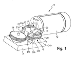
- FIGS. 1 to 6 show a preferred embodiment of the movement device 11 according to the invention.
- the movement device 11 is used to drive a movable Furniture part. These may be, for example, a furniture flap, a door, a drawer or the like.
- the movement device 11 has an actuator 12, which is formed in the example as an electric motor.
- the actuator 12 is designed as a reversing drive, which can be selectively switched between left and right rotation.
- the actuator 12 has a rotationally drivable drive shaft 13, on which a drive screw 14 is rotatably mounted, that is rotated in the rotational movement of the drive shaft 13 with.
- the movement device 11 further includes an output, which is driven by the actuator 12 and is coupled to the movable furniture part.
- the output comprises a driven gear 16 which is designed as a gear.
- a driven gear 16 which is designed as a gear.
- a pivotally driven actuator arm which is connected on the one hand with the driven gear and on the other hand with the furniture flap.
- a coupling device 15 which cooperates both with the actuator 12 and with the output and between the actuator 12 and the output, in particular its output gear 16 is arranged.
- the output gear 16 and the components of the clutch device 15 are mounted on a clutch carrier 17, wherein the output gear 16 is rotatably mounted about an axis of rotation on the clutch carrier 17.
- the coupling device 15 comprises an input gear 18 which is designed as a worm wheel and is constantly in engagement with the drive worm 14. A rotary drive movement the actuator 12 is thus always translated via the drive worm 14 in a rotational movement of the input gear 18.
- the input gear 18 is rotatably mounted on a rotatably mounted on the clutch carrier 17 rotating shaft 19. The rotational movement transmitted by the drive worm 14 is therefore transmitted via the input gear 18 to the rotary shaft 19.
- a worm wheel 20 is further rotatably mounted, which preferably has a larger diameter than the input gear 18. During the rotational movement of the rotary shaft 19, the worm wheel 20 is also moved, that is, it rotates synchronously with the input gear 18.
- the coupling device further comprises two output wheels 21a, 21b, which are each likewise designed as gearwheels.
- the output wheels 21a, 21b are each rotatably mounted on a pivot member 22 and are constantly in engagement with the worm wheel 20, are thus offset by this in rotation.
- Fig. 1 shows, the pivoting part is mounted pivotably about a pivot axis on the coupling carrier 17.
- the pivoting part 22 comprises two strap parts 23a, 23b which are arranged above and below the two gears mounted on the rotary shaft 19.
- the output wheels 21a, 21b are likewise arranged between the two bow parts 23a, 23b and are each rotatably mounted on an axis of rotation 24a, 24b, which in turn are fastened on the one hand to the upper and, on the other hand, to the lower bow part 23a, 23b.
- the pivoting of the pivot member 22 is limited by two arranged on the coupling support 17 pivot stops 26a, 26b.
- Mitschitz 25 are arranged at the upper bracket portion 23a, which provides for a delivery in each case one of the two output wheels 21a in response to the direction of rotation of the actuator 12 to the output gear 16.
- the entrainment means comprise a spring-loaded by means of a compression spring 27 pressure piece 28, the underside of which is designed as a contact surface 29 and is frictionally pressed by the compression spring into contact with the input gear 18.
- the compression spring 27 is supported on the one hand on an end face of a hollow cylindrical receiving part 30, which in turn is attached to the upper side of the upper bracket portion 23a.
- the compression spring 27 and the pressure piece 28 pass through the upper bracket portion 23 a via a through hole.
- Detection means 31 are provided, which cause the clutch device 15 to assume a neutral position 32 which decouples the output from the actuator 12 in at least one end position of the output.
- the detection means 31 include in the example, for example, a arranged on the clutch carrier 17 sensor 33, which is formed for example as a proximity sensor, in particular as a reed switch.
- a magnet 34 which is in the end position of the movable furniture part, ie in the closed and / or open position, in the effective range of the reed switch and this activated.
- the reed switch outputs a position signal which is transmitted directly or via a control device to the actuator, which causes a reversal of the direction of rotation.
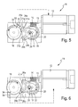
- FIG. 4 shows the neutral position 32 of the coupling device, which is present when the movable furniture part is in the closed or open position.
- both output wheels 21a, 21b are decoupled from the output gear 16, the actuator 12 is thus uncoupled from the output.
- the movable furniture part can be opened or closed by manual manipulation. This is advantageous if the actuator 12 is not functional due to a power failure or a defect.
- the movable furniture part thus remains movable, so that, for example, access to a furniture compartment is possible.
- the actuator is driven starting from the in FIG. 4 shown neutral position 32 activated.
- the magnet 34 activates the reed switch, which emits a position signal, whereby the actuator 12 is caused to reverse its direction of rotation.
- the pivot member is pivoted away from the output gear 16 until the neutral position 32 is reached.
- FIG. 6 shows the second coupling position 35b.
Landscapes
- Power-Operated Mechanisms For Wings (AREA)
Abstract
Description
- Die Erfindung betrifft eine Bewegungsvorrichtung für ein bewegbares Möbelteil, insbesondere Möbelklappe, Tür oder Schublade oder dergleichen, mit einem Stellantrieb und einem durch den Stellantrieb antreibbaren Abtrieb für das bewegliche Möbelteil, der wenigstens ein mit dem bewegbaren Möbelteil verbindbares Abtriebsteil aufweist, wobei eine zwischen dem Stellantrieb und dem Abtrieb eingeschaltete Kupplungseinrichtung vorgesehen ist.
- Derartige Bewegungsvorrichtungen für bewegbare Möbelteile, bei denen zwischen Stellantrieb und Abtrieb eine Kupplungseinrichtung angeordnet ist, sind bereits seit längerem bekannt.
- Die Kupplungseinrichtung sorgt dafür, dass das bewegbare Möbelteil auf zwei unterschiedliche Arten bewegt werden kann. Bei wirksamer Kupplung wird das bewegbare Möbelteil aktuorisch, insbesondere motorisch mittels des Stellantriebs angetrieben, beispielsweise im Falle einer Möbelklappe oder Schublade zwischen der Offen- und Schließstellung bewegt. Bei unwirksamer Kupplung sind Stellantrieb und Abtrieb voneinander getrennt und das bewegbare Möbelteil kann manuell bewegt werden. Dies ist vor allem dann wichtig, wenn der Stellantrieb defekt oder in Folge eines Energieausfalls nicht betriebsfähig ist. Insbesondere falls sich das bewegbare Möbelteil in einer seiner Endstellungen befindet, die im Falle einer Möbelklappe oder Schublade die Offen- oder Schließstellung sein kann, sollte bei Energieausfall oder Defekt des Stellantriebs eine manuelle Bewegung des bewegbaren Möbelteils möglich sein.
- Aufgabe der Erfindung ist es, eine Bewegungsvorrichtung der eingangs genannten Art zu schaffen, die einfach aufgebaut ist, zuverlässig bedienbar und relativ unempfindlich gegen Störeinflüsse ist.
- Diese Aufgabe wird durch eine Bewegungsvorrichtung mit den Merkmalen der unabhängigen Ansprüche 1 und 15 gelöst. Weiterbildungen der Erfindung sind in den Unteransprüchen dargestellt.
- Die erfindungsgemäße Bewegungsvorrichtung zeichnet sich dadurch aus, dass Erfassungsmittel vorgesehen sind, die hervorrufen, dass die Kupplungseinrichtung in wenigstens einer Endstellung des Abtriebs eine den Abtrieb vom Stellantrieb abkuppelnde Neutralstellung einnimmt.
- Durch die erfindungsgemäße Kupplungseinrichtung lässt sich das bewegbare Möbelteil auf zwei unterschiedliche Arten Öffnen und Schließen. Zum einen ist ein aktuorisches Öffnen oder Schließen des Stellantriebs möglich, wobei vorzugsweise die Öffnungsbewegung von der Schließstellung in die vollständige Offenstellung und umgekehrt komplett aktuorisch erfolgen kann. Ein wichtiger Aspekt ist, dass in wenigstens einer Endstellung des bewegbaren Möbelteils, insbesondere in beiden Endstellungen, Stellantrieb und Abtrieb über die Erfassungsmittel gesteuert getrennt werden. Dadurch ist es möglich, ein in der Schließ- und/oder Offenstellung befindliches bewegbares Möbelteil manuell zu bewegen, wodurch ein Öffnenund/oder Schließen auch bei Stromausfall oder Defekt des Stellantriebs in jedem Fall möglich ist. Beim Öffnenund/oder Schließen des bewegbaren Möbelteils ist es von Vorteil, dass nicht zunächst ausgekuppelt werden muss, d.h. der Stellantrieb vom Abtrieb aktiv durch Handhabe des Benutzers getrennt werden muss, wie es beispielsweise bei einer Überlastkupplung der Fall ist, sondern die manuelle Bewegung ist ohne zusätzlichen Kraftaufwand durchführbar da das bewegbare Möbelteil bereits abgekuppelt ist, wenn die manuelle Bewegung eingeleitet wird.
- Bei einer Weiterbildung der Erfindung sind die Erfassungsmittel einem Auskuppler zugeordnet, der von den Erfassungsmitteln derart ansteuerbar ist, dass bei Erreichung der Endstellung des Abtriebs ein Entkuppeln des Abtriebs vom Stellantrieb herbeiführbar ist. Zweckmäßigerweise erzeugen die Erfassungsmittel bei Erreichung des Abtriebs ein Signal, beispielsweise Positionssignal, dass dann durch geeignete Signalübertragung direkt oder unter Zwischenschaltung einer Steuereinrichtung an den Auskuppler übertragbar ist. Die Signalübertragung kann leitungsgestützt oder drahtlos erfolgen. Die drahtlose Signalübertragung kann mittels Funk- oder Infrarot-Signalen durchgeführt werden.
- In besonders bevorzugter Weise ist der Auskuppler vom Stellantrieb selber gebildet, der als reversierender Antrieb ausgebildet ist, der wahlweise zwischen Links- und Rechtslauf umschaltbar ist, wobei das Entkuppeln in der Endstellung durch eine Drehrichtungsumkehr des Stellantriebs erfolgt.
- Es ist also möglich, dass die Erfassungsmittel bei Erreichung einer Endstellung ein Positionssignal erzeugen, dass den Stellantrieb zu einer Drehrichtungsumkehr veranlasst, wodurch ein Auskuppeln bzw. Entkuppeln und damit Trennung von Stellantrieb und Abtrieb erfolgt.
- Bei einer Weiterbildung der Erfindung sind die Erfassungsmittel in den Stellantrieb integriert und erfassen eine aufgrund der Erhöhung des Widerstands beim Erreichen der Endstellung des Abtriebs sich ändernde, auf den Stellantrieb wirkende Kenngröße. Eine solche Kenngröße kann beispielsweise ein sich änderndes Drehmoment sein, das bei Erreichung der Endstellung sprunghaft größer wird. Alternativ wäre auch die Messung der Geschwindigkeit einer Antriebswelle des Stellantriebs oder die Messung der Verzögerung bzw. Bremswirkung an der Antriebswelle möglich.
- In besonders bevorzugter Weise sind die Erfassungsmittel dem Abtriebsteil zugeordnet und zur Abgabe von Steuersignalen zu Ansteuerung des Auskupplers, insbesondere Stellantriebs, ausgestaltet.
- Bei einer Weiterbildung der Erfindung weisen die Erfassungsmittel wenigstens einen Sensor auf, wobei vorzugsweise im Falle der Integration der Erfassungsmittel in den Stellantrieb ein Drehmomentsensor oder im Falle der dem Abtriebsteil zugeordneten Erfassungsmitteln ein Positionssensor vorgesehen ist. Als Positionssensor kann beispielsweise ein Näherungssensor verwendet werden. Als Näherungssensor lässt sich beispielsweise ein Reed-Schalter einsetzen.
- Bei einer Weiterbildung der Erfindung weist die Kupplungseinrichtung wenigstens ein Ausgangsrad auf, das in einer Kupplungsstellung mit dem Abtrieb gekuppelt oder in der Neutralstellung vom Abtrieb abgekuppelt ist.
- In besonders bevorzugter Weise sind zwei Ausgangsräder vorgesehen, von denen in der Kupplungsstellung in Abhängigkeit von einer Antriebsrichtung des Stellantriebs jeweils eines mit dem Abtrieb gekuppelt und das andere vom Abtrieb abgekuppelt ist.
- Bei einer Weiterbildung der Erfindung weist die Kupplungseinrichtung wenigstens ein mit dem Stellantrieb kuppelbares oder gekuppeltes Eingangsrad auf, das mit dem wenigstens einen Ausgangsrad über Mitnehmermittel derart verbindbar oder verbunden ist, dass zum Einkuppeln ausgehend von der Neutralstellung eine Zustellbewegung des wenigstens einen Ausgangsrads hin zum Abtrieb mit anschließendem Einkuppeln stattfindet. Zweckmäßigerweise wirken die Mitnehmermittel also zwischen dem Eingangsrad und dem wenigstens einen Ausgangsrad, wobei zum Ein- oder Auskuppeln des wenigstens einen Ausgangsrads mit dem Abtrieb eine durch die Mitnehmermittel übertragene Stellbewegung stattfindet.
- Bei einer Weiterbildung der Erfindung ist das Eingangsrad stets mit dem Stellantrieb gekuppelt.
- Es ist möglich, dass das wenigstens eine Ausgangsrad an einem Schwenkteil drehbar gelagert ist, und die Zustellbewegung zum Einkupppeln über eine Schwenkbewegung des Schwenkteils erfolgt. Im Falle von zwei Ausgangrädern werden zweckmäßigerweise beide an dem Schwenkteil drehbar gelagert. Der Schwenkweg des Schwenkteils kann durch Anschlagflächen begrenzt werden.
- Bei einer Weiterbildung der Erfindung weisen die Mitnehmermittel wenigstens ein Reibschlusselement auf, wobei die Kraftübertragung zwischen dem Eingangsrad und dem Ausgangsrad zu Herbeiführung der Zustellbewegung über einen Reibschluss erfolgt. Das Reibschlusselement kann beispielsweise mittels Feder der Federkraft an das Eingangsrad gedrückt werden. Hierzu kann beispielsweise ein federbelastetes Druckstück eingesetzt werden. Zweckmäßigerweise sitzt das Reibschlusselement am Schwenkteil. Als Alternative zum Reibschluss zwischen Eingangsrad und Ausgangsrad könnte auch eine Kraftübertragung mittels Formschluss, beispielsweise durch Rastmittel erfolgen.
- Bei einer Weiterbildung der Erfindung ist die Kupplungseinrichtung als Zahnrad-Kupplung ausgebildet, wobei sowohl das wenigstens eine Eingangsrad als auch das wenigstens eine Ausgangsrad als Zahnräder ausgebildet sind.
- Prinzipiell wären jedoch auch andere Arten von Kraftübertragungsmitteln einsetzbar, beispielsweise könnte zwischen dem Stellantrieb und dem Abtrieb ein Riemengetriebe angeordnet sein.
- Bei einer Weiterbildung der Erfindung ist der Stellantrieb als Elektromotor, insbesondere Servo- oder Schrittmotor, ausgebildet. Prinzipiell wären auch fluidisch betriebene Stellantriebe einsetzbar.
- Die Erfindung umfasst ferner eine Bewegungsvorrichtung für ein bewegbares Möbelteil, insbesondere Möbelklappe, Tür oder Schublade oder dergleichen, mit einem Stellantrieb und einem durch den Stellantrieb antreibbaren Abtrieb für das bewegliche Möbelteil, der wenigstens ein mit dem bewegbaren Möbelteil verbindbares Abtriebsteil aufweist, wobei eine zwischen dem Stellantrieb und dem Abtrieb eingeschaltete Kupplungseinrichtung vorgesehen ist, die eine den Abtrieb mit dem Stellantrieb koppelnde Kupplungsstellung oder eine den Abtrieb vom Stellantrieb abkuppelnde Neutralstellung einnehmen kann, wobei sich die Bewegungsvorrichtung dadurch auszeichnet, dass die Kupplungseinrichtung Kupplungsmittel aufweist, die derart ausgebildet sind, dass bei einem mittels des Stellantriebs bewirkten Antreiben des Abtriebs der dadurch in einer Abtriebsrichtung mit Abtriebsgeschwindigkeit bewegt wird, eine in Abtriebsrichtung wirkende Zusatzbewegung gegenüber der Abtriebsgeschwindigkeit höhere Geschwindigkeit ermöglicht ist.
- Eine derartige Ausgestaltung ermöglicht eine Überholfunktion derart, dass beispielsweise bei einer aktuorischen Schließbewegung des bewegbaren Möbelteils mittels des Stellantriebs zusätzlich aktiv das bewegbare Möbelteil manuell gegriffen und mit einer gegenüber der aktuorischen Schließgeschwindigkeit höheren Schließgeschwindigkeit geschlossen werden kann.
- Gleiches gilt selbstverständlich auch für das Öffnen des bewegbaren Möbelteils.
- Bei einer Weiterbildung der Erfindung weisen die Kupplungsmittel wenigstens ein Ausgangsrad auf, das in einer Kupplungsstellung mit dem Abtrieb gekuppelt und in der Neutralstellung vom Abtrieb abgekuppelt ist, wobei das wenigstens eine Ausgangsrad bei Einleitung der Zusatzbewegung vom Abtrieb abkuppelbar und in die Neutralstellung bewegbar ist und von dort bei Beendigung der Zusatzbewegung zurück in die Kupplungsstellung bewegbar ist. In diesem Fall führt also die Zusatzbewegung, die während einer aktuorischen Stellbewegung eingeleitet wird zu einem Auskuppeln.
- Die Erfindung umfasst ferner noch ein Möbelteil, insbesondere Klappe, gekennzeichnet durch eine Bewegungsvorrichtung nach einem der Ansprüche 1 bis 17.
- Schließlich umfasst die Erfindung noch ein Möbel, mit wenigstens einem bewegbaren Möbelteil, insbesondere Klappe, gekennzeichnet durch eine Bewegungsvorrichtung nach einem der Ansprüche 1 bis 17.
- Ein bevorzugtes Ausführungsbeispiel der Erfindung ist in der Zeichnung dargestellt und wird im Folgenden näher erläutert. In der Zeichnung zeigen:
- Figur 1
- eine perspektivische Darstellung eines bevorzugten Ausführungsbeispiels der erfindungsgemäßen Bewegungsvorrichtung,
- Figur 2
- einen Schnitt durch die Bewegungsvorrichtung von
Figur 1 entlang der Linie II-II ausFigur 4 , - Figur 3
- eine vergrößerte Darstellung der Einzelheit X aus
Figur 2 , - Figur 4
- eine Draufsicht auf die Bewegungsvorrichtung von
Figur 1 , wobei die Kupplungsstellung die Neutralstellung einnimmt, - Figur 5
- eine Draufsicht auf die Bewegungsvorrichtung von
Figur 1 , wobei die Kupplungseinrichtung eine erste Kupplungsstellung einnimmt und - Figur 6
- eine Draufsicht auf die Bewegungsvorrichtung von
Figur 1 , wobei die Kopplungseinrichtung eine zweite Kupplungsstellung einnimmt. - Die
Figuren 1 bis 6 zeigen ein bevorzugtes Ausführungsbeispiel der erfindungsgemäßen Bewegungsvorrichtung 11. Die Bewegungsvorrichtung 11 dient zum Antreiben eines bewegbaren Möbelteils. Dies können beispielsweise eine Möbelklappe, eine Tür, eine Schublade oder dergleichen sein. - Die Bewegungsvorrichtung 11 besitzt einen Stellantrieb 12, der im Beispielsfall als Elektromotor ausgebildet ist. Der Stellantrieb 12 ist als reversierender Antrieb ausgebildet, der wahlweise zwischen Links- und Rechtslauf umschaltbar ist. Der Stellantrieb 12 besitzt eine rotatorisch antreibbare Antriebswelle 13, auf der eine Antriebsschnecke 14 drehfest gelagert ist, also bei der Rotationsbewegung der Antriebswelle 13 mit rotiert wird.
- Die Bewegungsvorrichtung 11 umfasst ferner einen Abtrieb, der durch den Stellantrieb 12 antreibbar ist und mit dem bewegbaren Möbelteil gekoppelt ist. Der Abtrieb umfasst ein Abtriebsrad 16 das als Zahnrad ausgebildet ist. Im Falle eines als Möbelklappe ausgebildeten bewegbaren Möbelteils kann der Abtrieb beispielsweise einen schwenkbeweglich antreibbaren Stellarm umfassen, der einerseits mit dem Abtriebsrad und andererseits mit der Möbelklappe verbunden ist.
- Es ist ferner eine Kupplungseinrichtung 15 vorgesehen, die sowohl mit dem Stellantrieb 12 als auch mit dem Abtrieb zusammenwirkt und zwischen dem Stellantrieb 12 und dem Abtrieb, insbesondere dessen Abtriebsrad 16 angeordnet ist. Das Abtriebsrad 16 und die Komponenten der Kupplungseinrichtung 15 sind an einem Kupplungsträger 17 gelagert, wobei das Abtriebsrad 16 um eine Drehachse drehbar am Kupplungsträger 17 montiert ist.
- Die Kupplungseinrichtung 15 umfasst ein Eingangsrad 18, das als Schneckenrad ausgebildete ist und ständig in Eingriff mit der Antriebssschnecke 14 steht. Eine rotatorische Antriebsbewegung des Stellantriebs 12 wird also stets über die Antriebsschnecke 14 in eine rotatorische Bewegung des Eingangsrads 18 übersetzt. Das Eingangsrad 18 ist drehfest an einer am Kupplungsträger 17 drehbar befestigten Drehwelle 19 montiert. Die von der Antriebsschnecke 14 übertragene Drehbewegung wird also über das Eingangsrad 18 auf die Drehwelle 19 übertragen.
- Auf der Drehwelle 19 ist ferner ein Schneckenrad 20 drehfest montiert, das vorzugsweise einen größeren Durchmesser als das Eingangsrad 18 aufweist. Bei der Drehbewegung der Drehwelle 19 wird das Schneckenrad 20 mit bewegt, dreht sich also synchron zum Eingangsrad 18.
- Die Kupplungseinrichtung umfasst ferner zwei Ausgangsräder 21a, 21b, die jeweils ebenfalls als Zahnräder ausgebildet sind. Die Ausgangsräder 21a, 21b sind jeweils an einem Schwenkteil 22 drehbar gelagert und stehen ständig in Eingriff mit dem Schneckenrad 20, werden durch dieses also in Drehbewegung versetzt.
- Wie insbesondere
Fig. 1 zeigt, ist das Schwenkteil um eine Schwenkachse schwenkbar am Kupplungsträger 17 gelagert. Das Schwenkteil 22 umfasst zwei Bügelteile 23a, 23b die ober- und unterhalb der beiden an der Drehwelle 19 gelagerten Zahnräder angeordnet sind. Die Ausgangsräder 21a, 21b sind ebenfalls zwischen den beiden Bügelteilen 23a, 23b angeordnet und jeweils an einer Drehachse 24a, 24b drehbar gelagert, die wiederum einerseits am oberen und andererseits am unteren Bügelteil 23a, 23b befestigt sind. Der Schwenkweg des Schwenkteils 22 ist durch zwei am Kupplungsträger 17 angeordnete Schwenkanschläge 26a, 26b begrenzt. - Am oberen Bügelteil 23a sind Mitnehmermittel 25 angeordnet, die für eine Zustellung jeweils eines der beiden Ausgangsräder 21a in Abhängigkeit von der Drehrichtung des Stellantriebs 12 an das Abtriebsrad 16 sorgt.
- Wie insbesondere in
Figur 3 gezeigt umfassen die Mitnehmermittel ein mittels einer Druckfeder 27 federbelastetes Druckstück 28, dessen Unterseite als Kontaktfläche 29 ausgebildet ist und mittels der Druckfeder reibschlüssig in Anlage zum Eingangsrad 18 gedrückt ist. Die Druckfeder 27 stützt sich dabei einerseits an einer Stirnfläche eines hohlzylindrischen Aufnahmeteils 30 ab, das wiederum an der Oberseite des oberen Bügelteils 23a befestigt ist. Die Druckfeder 27 und das Druckstück 28 durchsetzen das obere Bügelteil 23a über ein Durchgangsloch. - Wie insbesondere in den
Figuren 4 bis 6 gezeigt sind Erfassungsmittel 31 vorgesehen, die hervorrufen, dass die Kupplungseinrichtung 15 in wenigstens einer Endstellung des Abtriebs eine den Abtrieb vom Stellantrieb 12 abkuppelnde Neutralstellung 32 einnimmt. Die Erfassungsmittel 31 umfassen im Beispielsfall einen beispielsweise am Kupplungsträger 17 angeordneten Sensor 33, der beispielsweise als Näherungssensor, insbesondere als Reed-Schalter ausgebildet ist. - Am Außenumfang des Abtriebsrads 16 sitzt stirnseitig ein Magnet 34, der in der Endstellung des bewegbaren Möbelteils, also in der Schließ- und/oder Offenstellung, im Wirkbereich des Reed-Schalters ist und diesen aktiviert. Der Reed-Schalter gibt ein Positionssignal aus, das direkt oder über eine Steuereinrichtung an den Stellantrieb übertragen wird, der zu einer Drehrichtungsumkehr veranlasst wird.
-
Figur 4 zeigt die Neutralstellung 32 der Kupplungseinrichtung, die vorliegt, wenn sich das bewegbare Möbelteil in der Schließ- oder Offenstellung befindet. In der Neutralstellung 32 sind beide Ausgangsräder 21a, 21b vom Abtriebsrad 16 entkuppelt, der Stellantrieb 12 ist also vom Abtrieb abgekuppelt. In dieser Stellung lässt sich das bewegbare Möbelteil durch manulle Handhabe Öffnen oder Schließen. Dies ist von Vorteil, falls der Stellantrieb 12 aufgrund eines Stromausfalls oder eines Defekts nicht funktionsfähig ist. Das bewegbare Möbelteil bleibt also bewegbar, so dass beispielsweise ein Zugang zu einem Möbelfach möglich ist. - Soll das bewegbare Möbelteil bei funktionsfähigem Stellantrieb aktuorisch bewegt werden, so wird der Stellantrieb ausgehend von der in
Figur 4 gezeigten Neutralstellung 32 aktiviert. - Die Rotationsbewegung der Antriebsschnecke 14 wird dabei auf das Eingangsrad 18 übertragen, das in Drehbewegung versetzt wird. Infolge des Reibschlusses zwischen dem Druckstück 28 und dem Eingangsrad 18 wird das Schwenkteil 22 um seine Schwenkachse verschwenkt, so dass wie beispielsweise in
Figur 5 bei einer Drehrichtung des Eingangsrads 18 im GegenUhrzeigersinn gezeigt, das obere Ausgangsrad 21a, in Richtung zum Abtriebsrad 16 geschwenkt wird, so dass es in Eingriff mit diesem kommt. Steht das Ausgangrad 21a in Eingriff mit dem Abtriebsrad 16, so rutscht das Eingangsrad 18 durch, d.h. der Reibschluss des Druckstücks kann nicht mehr gehalten werden. Ein weiterschwenken des Schwenkteils ist ohnehin nicht möglich, das dieses an den Schwenkanschlag 26a anschlägt. - In dieser Stellung wird die Drehbewegung des Eingangsrads 18 über die Drehwelle 19 an das Schneckenrad 20 und von dort auf das in der ersten Kupplungsstellung 35a befindliche Ausgangsrad 21a, übertragen, dessen Drehbewegung dann auf das Abtriebsrad 16 übertragen wird. Die Drehbewegung des Abtriebsrads 16 wird dann in eine Schließ- oder Öffnungsbewegung des bewegbaren Möbelteils umgesetzt.
- Fährt das bewegbare Möbelteil dann in die Schließ- oder Offenstellung ein, so aktiviert der Magnet 34 den Reed-Schalter, der ein Positionssignal abgibt, wodurch der Stellantrieb 12 veranlasst wird seine Drehrichtung umzukehren. Über den Reibschluss zwischen Druckstück und Eingangsrad 18 wird das Schwenkteil vom Abtriebsrad 16 weggeschwenkt bis die Neutralstellung 32 erreicht ist.
- Soll das bewegbare Möbelteil dann aus der erreichten Endstellung aktuorisch in die andere Stellung überführt werden, so wird die Drehrichtung des Stellantriebs beibehalten, so das über eine Verschwenkung des Schwenkteils 22 das untere Ausgangsrad 21b in Eingriff mit dem Abtriebsrad 16 gefahren wird.
Figur 6 zeigt dabei die zweite Kupplungsstellung 35b. - Ein wichtiger Aspekt ist, dass bei der aktuarischen Öffnungsoder Schließbewegung eine Überholfunktion gegegben ist. Der Benutzer kann das bewegbare Möbelteil also schneller Öffnen oder Schließen als das mit dem Stellantrieb 12 möglich ist. Dabei wird das Abtriebsrad 16 schneller als das gerade in Eingriff mit ihm stehende Ausgangrad 21a, 21b drehbewegt, wodurch dieses über die Verschwenkbarkeit des Schwenkteils 22 nach außen ausweicht.
Claims (19)
- Bewegungsvorrichtung für ein bewegbares Möbelteil, insbesondere Möbelklappe, Tür oder Schublade o. dgl., mit einem Stellantrieb (12) und einem durch den Stellantrieb (12) antreibbaren Abtrieb für das bewegliche Möbelteil, der wenigstens ein mit dem bewegbaren Möbelteil verbindbares Abtriebsteil aufweist, wobei eine zwischen dem Stellantrieb (12) und dem Abtrieb eingeschaltete Kupplungseinrichtung (15) vorgesehen ist, dadurch gekennzeichnet, dass Erfassungsmittel (31) vorgesehen sind, die hervorrufen, dass die Kupplungseinrichtung (15) in wenigstens einer Endstellung des Abtriebs eine den Abtrieb vom Stellantrieb abkuppelnde Neutralstellung (32) einnimmt.
- Bewegungsvorrichtung nach Anspruch 1, dadurch gekennzeichnet, dass die Erfassungsmittel (31) einem Auskuppler zugeordnet sind, der von den Erfassungsmitteln (31) derart ansteuerbar ist, dass bei Erreichen der Endstellung des Abtriebs ein Entkuppeln von Abtrieb und Stellantrieb (12) herbeiführbar ist.
- Bewegungsvorrichtung nach Anspruch 2, dadurch gekennzeichnet, dass der Auskuppler vom Stellantrieb (12) selber gebildet ist, der als reversierender Antrieb ausgebildet ist, der wahlweise zwischen Links- und Rechtslauf umschaltbar ist, wobei das Entkuppeln in der Endstellung durch eine Drehrichtungsumkehr des Stellantriebs (12) erfolgt.
- Bewegungsvorrichtung nach einem der vorhergehenden Ansprüche, dadurch gekennzeichnet, dass die Erfassungsmittel (31) in den Stellantrieb (12) integriert sind und eine aufgrund der Erhöhung des Widerstandes beim Erreichen der Endstellung des Abtriebs sich ändernde, auf den Stellantrieb (12) wirkende Kenngröße, beispielsweise Drehmoment, erfassen.
- Bewegungsvorrichtung nach einem der vorhergehenden Ansprüche, dadurch gekennzeichnet, dass die Erfassungsmittel (31) dem Abtriebsteil zugeordnet sind und zur Abgabe von Steuersignalen zur Ansteuerung des Auskupplers, insbesondere Stellantriebs (12), ausgestaltet sind.
- Bewegungsvorrichtung nach einem der vorhergehenden Ansprüche, dadurch gekennzeichnet, dass die Erfassungsmittel (31) wenigstens einen Sensor (33) aufweisen, wobei vorzugsweise im Falle der Integration der Erfassungsmittel (31) in den Stellantrieb (12) ein Drehmomentsensor oder im Falle der dem Abtriebsteil zugeordneten Erfassungsmittel ein Positionssensor, beispielsweise Näherungssensor, vorgesehen ist.
- Bewegungsvorrichtung nach einem der vorhergehenden Ansprüche, dadurch gekennzeichnet, dass die Kupplungseinrichtung (15) wenigstens ein Ausgangsrad (21a, 21b) aufweist, das in einer Kupplungsstellung mit dem Abtrieb gekuppelt und in der Neutralstellung (32) vom Abtrieb abgekuppelt ist.
- Bewegungsvorrichtung nach Anspruch 7, dadurch gekennzeichnet, dass zwei Ausgangsräder vorgesehen sind, von denen in der Kupplungsstellung (35a, 35b) in Abhängigkeit von einer Antriebsrichtung des Stellantriebs (12) jeweils eines mit dem Abtrieb gekuppelt und das andere vom Abtrieb abgekuppelt ist.
- Bewegungsvorrichtung nach einem der Ansprüche 7 oder 8, dadurch gekennzeichnet, dass die Kupplungseinrichtung (15) wenigstens ein mit dem Stellantrieb (12) kuppelbares oder gekuppeltes Eingangsrad (18) aufweist, das mit dem wenigstens einen Ausgangsrad (21a, 21b) über Mitnehmermittel (25) derart verbindbar oder verbunden ist, dass zum Einkuppeln ausgehend von der Neutralstellung (32) eine Zustellbewegung des wenigstens einen Ausgangsrades (21a, 21b) hin zum Abtrieb mit anschließendem Einkuppeln stattfindet.
- Bewegungsvorrichtung nach Anspruch 9, dadurch gekennzeichnet, dass das Eingangsrad (18) stets mit dem Stellantrieb (12) gekuppelt ist.
- Bewegungsvorrichtung nach Anspruch 9 oder 10, dadurch gekennzeichnet, dass das wenigstens eine Ausgangsrad (21a, 21b) an einem Schwenkteil (22) drehbar gelagert ist, und die Zustellbewegung zum Einkuppeln über eine Schwenkbewegung des Schwenkteils (22) erfolgt.
- Bewegungsvorrichtung nach einem der Ansprüche 7 bis 11, dadurch gekennzeichnet, dass die Mitnehmermittel (25) wenigstens ein Reibschlusselement aufweisen und die Kraftübertragung zwischen dem Eingangsrad (18) und dem Ausgangsrad (21a, 21b) zur Herbeiführung der Zustellbewegung über einen Reibschluss erfolgt.
- Bewegungsvorrichtung nach einem der Ansprüche 7 bis 12, dadurch gekennzeichnet, dass die Kupplungseinrichtung (15) als Zahnrad-Kupplung ausgebildet ist und sowohl das wenigstens eine Eingangsrad (18) als auch das wenigstens eine Ausgangsrad (21a, 21b) als Zahnräder ausgebildet sind.
- Bewegungsvorrichtung nach einem der vorhergehenden Ansprüche, dadurch gekennzeichnet, dass der Stellantieb (12) als Elektromotor, insbesondere Servo- oder Schrittmotor, ausgebildet ist.
- Bewegungsvorrichtung für ein bewegbares Möbelteil, insbesondere Möbelklappe, Tür oder Schublade o. dgl., mit einem Stellantrieb (12) und einem durch den Stellantrieb (12) antreibbaren Abtrieb für das bewegliche Möbelteil, der wenigstens ein mit dem bewegbaren Möbelteil verbindbares Abtriebsteil aufweist, wobei eine zwischen dem Stellantrieb (12) und dem Abtrieb eingeschaltete Kupplungseinrichtung (15) vorgesehen ist, die eine den Abtrieb mit dem Stellantrieb (12) kuppelnde Kupplungsstellung (35a, 35b) oder eine den Abtrieb vom Stellantrieb (12) abkuppelnde Neutralstellung (32) einnehmen kann, dadurch gekennzeichnet, dass die Kupplungseinrichtung Kupplungsmittel aufweist, die derart ausgebildet sind, dass bei einem mittels des Stellantriebs (12) bewirkten Antreiben des Abtriebs, der dadurch in einer Abtriebsrichtung mit Abtriebsgeschwindigkeit bewegt wird, eine in Abtriebsrichtung wirkende Zusatzbewegung mit gegenüber der Abtriebsgeschwindigkeit höherer Geschwindigkeit ermöglicht ist.
- Bewegungsvorrichtung nach Anspruch 15, dadurch gekennzeichnet, dass die Kupplungsmittel wenigstens ein Ausgangsrad (21a, 21b) aufweisen, das in einer Kupplungsstellung (35a, 35b) mit dem Abtrieb gekuppelt und in der Neutralstellung (32) vom Abtrieb abgekuppelt ist, wobei das wenigstens eine Ausgangsrad (21a, 21b) bei Einleitung der Zusatzbewegung vom Abtrieb abkuppelbar und in die Neutralstellung (32) bewegbar ist und von dort bei Beendigung der Zusatzbewegung zurück in die Kupplungsstellung (35a, 35b) bewegbar ist.
- Bewegungsvorrichtung nach Anspruch 15 oder 16, gekennzeichnet durch wenigstens ein Merkmal der Ansprüche 1 bis 14.
- Möbelteil, insbesondere Klappe, gekennzeichnet durch eine Bewegungsvorrichtung (11) nach einem der Ansprüche 1 bis 17.
- Möbel, mit wenigstens einem bewegbaren Möbelteil, insbesondere Klappe, gekennzeichnet durch eine Bewegungsvorrichtung (11) nach einem der Ansprüche 1 bis 18.
Applications Claiming Priority (1)
| Application Number | Priority Date | Filing Date | Title |
|---|---|---|---|
| DE202012009443.2U DE202012009443U1 (de) | 2012-10-01 | 2012-10-01 | Bewegungsvorrichtung für ein bewegbares Möbelteil |
Publications (3)
| Publication Number | Publication Date |
|---|---|
| EP2712998A2 true EP2712998A2 (de) | 2014-04-02 |
| EP2712998A3 EP2712998A3 (de) | 2017-10-11 |
| EP2712998B1 EP2712998B1 (de) | 2020-02-26 |
Family
ID=49263090
Family Applications (1)
| Application Number | Title | Priority Date | Filing Date |
|---|---|---|---|
| EP13004634.5A Active EP2712998B1 (de) | 2012-10-01 | 2013-09-24 | Bewegungsvorrichtung für ein bewegbares möbelteil |
Country Status (2)
| Country | Link |
|---|---|
| EP (1) | EP2712998B1 (de) |
| DE (1) | DE202012009443U1 (de) |
Family Cites Families (4)
| Publication number | Priority date | Publication date | Assignee | Title |
|---|---|---|---|---|
| US5878530A (en) * | 1994-10-18 | 1999-03-09 | Eccleston Mechanical | Remotely controllable automatic door operator permitting active and passive door operation |
| US6904717B2 (en) * | 1995-07-12 | 2005-06-14 | Valeo Electrical Systems, Inc. | Method for controlling a power sliding van door |
| US7547058B2 (en) * | 2006-05-15 | 2009-06-16 | Ford Global Technologies, Llc | System and method for operating an automotive liftgate |
| DE202010016982U1 (de) * | 2010-12-23 | 2012-04-02 | Grass Gmbh | Bewegungsvorrichtung |
-
2012
- 2012-10-01 DE DE202012009443.2U patent/DE202012009443U1/de not_active Expired - Lifetime
-
2013
- 2013-09-24 EP EP13004634.5A patent/EP2712998B1/de active Active
Non-Patent Citations (1)
| Title |
|---|
| None |
Also Published As
| Publication number | Publication date |
|---|---|
| EP2712998A3 (de) | 2017-10-11 |
| EP2712998B1 (de) | 2020-02-26 |
| DE202012009443U1 (de) | 2014-01-07 |
Similar Documents
| Publication | Publication Date | Title |
|---|---|---|
| EP3899180B1 (de) | Aufstellvorrichtung für ein kraftfahrzeugtürelement | |
| EP1929112B1 (de) | Möbelscharnier | |
| EP3271535B1 (de) | Kraftfahrzeugtür | |
| DE102018201840A1 (de) | Kraft-seitentürbetätigungsglied mit drehender antriebsmutter | |
| EP2248981A1 (de) | Klappenbeschlag für eine Möbelklappe und Möbel | |
| WO2013075702A1 (de) | Vorrichtung zur elektromotorischen betätigung einer tür | |
| DE19835915A1 (de) | Betätigungseinrichtung für einen Vorhang | |
| DE202010016982U1 (de) | Bewegungsvorrichtung | |
| DE102009006948A1 (de) | Vorrichtung und Verfahren zur elektromotorischen Betätigung einer Tür | |
| DE10297107T5 (de) | Einfach zu betätigender Türöffnungsmechanismus zum selektiven Typ für ein Fahrzeugtürschloss | |
| WO2020125853A1 (de) | Aufstellvorrichtung für ein kraftfahrzeugtürelement | |
| DE10313440A1 (de) | Vorrichtung zum automatischen Verschwenken einer auch manuell betätigbaren Fahrzeugtür | |
| DE102006027857A1 (de) | Klappenantrieb | |
| DE3730114A1 (de) | Vorrichtung zum oeffnen und schliessen von tueren | |
| DE102012108366B3 (de) | Türeinheit | |
| EP2378924B1 (de) | Auslösesensor für einen möbelantrieb | |
| DE102009059881A1 (de) | Türeinheit | |
| DE102009036870A1 (de) | Türeinheit | |
| DE4414989C2 (de) | Verriegelungsmechanik für ein Schloßsystem | |
| DE202009012289U1 (de) | Elektronisches Verschlusssystem für Schränke mit einer im Schrankinneren angeordneten elektromotorisch gesteuerten Verriegelungsmechanik | |
| EP2712998B1 (de) | Bewegungsvorrichtung für ein bewegbares möbelteil | |
| EP2712996B1 (de) | Bewegungsvorrichtung für ein bewegbares Möbelteil | |
| DE102012110484A1 (de) | Elektromechanische Kupplung für ein Panikschloss | |
| WO2012013183A2 (de) | Türeinheit | |
| DE10327450B4 (de) | Kraftfahrzeugtürverschluss |
Legal Events
| Date | Code | Title | Description |
|---|---|---|---|
| PUAI | Public reference made under article 153(3) epc to a published international application that has entered the european phase |
Free format text: ORIGINAL CODE: 0009012 |
|
| AK | Designated contracting states |
Kind code of ref document: A2 Designated state(s): AL AT BE BG CH CY CZ DE DK EE ES FI FR GB GR HR HU IE IS IT LI LT LU LV MC MK MT NL NO PL PT RO RS SE SI SK SM TR |
|
| AX | Request for extension of the european patent |
Extension state: BA ME |
|
| PUAL | Search report despatched |
Free format text: ORIGINAL CODE: 0009013 |
|
| AK | Designated contracting states |
Kind code of ref document: A3 Designated state(s): AL AT BE BG CH CY CZ DE DK EE ES FI FR GB GR HR HU IE IS IT LI LT LU LV MC MK MT NL NO PL PT RO RS SE SI SK SM TR |
|
| AX | Request for extension of the european patent |
Extension state: BA ME |
|
| RIC1 | Information provided on ipc code assigned before grant |
Ipc: E05F 15/10 00000000AFI20170901BHEP |
|
| STAA | Information on the status of an ep patent application or granted ep patent |
Free format text: STATUS: REQUEST FOR EXAMINATION WAS MADE |
|
| 17P | Request for examination filed |
Effective date: 20180410 |
|
| RBV | Designated contracting states (corrected) |
Designated state(s): AL AT BE BG CH CY CZ DE DK EE ES FI FR GB GR HR HU IE IS IT LI LT LU LV MC MK MT NL NO PL PT RO RS SE SI SK SM TR |
|
| RAP1 | Party data changed (applicant data changed or rights of an application transferred) |
Owner name: GRASS GMBH |
|
| REG | Reference to a national code |
Ref country code: DE Ref legal event code: R079 Ref document number: 502013014327 Country of ref document: DE Free format text: PREVIOUS MAIN CLASS: E05F0015100000 Ipc: E05F0015603000 |
|
| RIC1 | Information provided on ipc code assigned before grant |
Ipc: E05F 15/603 20150101AFI20190812BHEP |
|
| GRAP | Despatch of communication of intention to grant a patent |
Free format text: ORIGINAL CODE: EPIDOSNIGR1 |
|
| STAA | Information on the status of an ep patent application or granted ep patent |
Free format text: STATUS: GRANT OF PATENT IS INTENDED |
|
| INTG | Intention to grant announced |
Effective date: 20191011 |
|
| GRAS | Grant fee paid |
Free format text: ORIGINAL CODE: EPIDOSNIGR3 |
|
| GRAA | (expected) grant |
Free format text: ORIGINAL CODE: 0009210 |
|
| STAA | Information on the status of an ep patent application or granted ep patent |
Free format text: STATUS: THE PATENT HAS BEEN GRANTED |
|
| AK | Designated contracting states |
Kind code of ref document: B1 Designated state(s): AL AT BE BG CH CY CZ DE DK EE ES FI FR GB GR HR HU IE IS IT LI LT LU LV MC MK MT NL NO PL PT RO RS SE SI SK SM TR |
|
| REG | Reference to a national code |
Ref country code: GB Ref legal event code: FG4D Free format text: NOT ENGLISH |
|
| REG | Reference to a national code |
Ref country code: CH Ref legal event code: EP |
|
| REG | Reference to a national code |
Ref country code: AT Ref legal event code: REF Ref document number: 1237817 Country of ref document: AT Kind code of ref document: T Effective date: 20200315 |
|
| REG | Reference to a national code |
Ref country code: IE Ref legal event code: FG4D Free format text: LANGUAGE OF EP DOCUMENT: GERMAN |
|
| REG | Reference to a national code |
Ref country code: DE Ref legal event code: R096 Ref document number: 502013014327 Country of ref document: DE |
|
| PG25 | Lapsed in a contracting state [announced via postgrant information from national office to epo] |
Ref country code: RS Free format text: LAPSE BECAUSE OF FAILURE TO SUBMIT A TRANSLATION OF THE DESCRIPTION OR TO PAY THE FEE WITHIN THE PRESCRIBED TIME-LIMIT Effective date: 20200226 Ref country code: NO Free format text: LAPSE BECAUSE OF FAILURE TO SUBMIT A TRANSLATION OF THE DESCRIPTION OR TO PAY THE FEE WITHIN THE PRESCRIBED TIME-LIMIT Effective date: 20200526 Ref country code: FI Free format text: LAPSE BECAUSE OF FAILURE TO SUBMIT A TRANSLATION OF THE DESCRIPTION OR TO PAY THE FEE WITHIN THE PRESCRIBED TIME-LIMIT Effective date: 20200226 |
|
| REG | Reference to a national code |
Ref country code: NL Ref legal event code: MP Effective date: 20200226 |
|
| REG | Reference to a national code |
Ref country code: LT Ref legal event code: MG4D |
|
| PG25 | Lapsed in a contracting state [announced via postgrant information from national office to epo] |
Ref country code: IS Free format text: LAPSE BECAUSE OF FAILURE TO SUBMIT A TRANSLATION OF THE DESCRIPTION OR TO PAY THE FEE WITHIN THE PRESCRIBED TIME-LIMIT Effective date: 20200626 Ref country code: GR Free format text: LAPSE BECAUSE OF FAILURE TO SUBMIT A TRANSLATION OF THE DESCRIPTION OR TO PAY THE FEE WITHIN THE PRESCRIBED TIME-LIMIT Effective date: 20200527 Ref country code: HR Free format text: LAPSE BECAUSE OF FAILURE TO SUBMIT A TRANSLATION OF THE DESCRIPTION OR TO PAY THE FEE WITHIN THE PRESCRIBED TIME-LIMIT Effective date: 20200226 Ref country code: SE Free format text: LAPSE BECAUSE OF FAILURE TO SUBMIT A TRANSLATION OF THE DESCRIPTION OR TO PAY THE FEE WITHIN THE PRESCRIBED TIME-LIMIT Effective date: 20200226 Ref country code: LV Free format text: LAPSE BECAUSE OF FAILURE TO SUBMIT A TRANSLATION OF THE DESCRIPTION OR TO PAY THE FEE WITHIN THE PRESCRIBED TIME-LIMIT Effective date: 20200226 Ref country code: BG Free format text: LAPSE BECAUSE OF FAILURE TO SUBMIT A TRANSLATION OF THE DESCRIPTION OR TO PAY THE FEE WITHIN THE PRESCRIBED TIME-LIMIT Effective date: 20200526 |
|
| PG25 | Lapsed in a contracting state [announced via postgrant information from national office to epo] |
Ref country code: NL Free format text: LAPSE BECAUSE OF FAILURE TO SUBMIT A TRANSLATION OF THE DESCRIPTION OR TO PAY THE FEE WITHIN THE PRESCRIBED TIME-LIMIT Effective date: 20200226 |
|
| PG25 | Lapsed in a contracting state [announced via postgrant information from national office to epo] |
Ref country code: PT Free format text: LAPSE BECAUSE OF FAILURE TO SUBMIT A TRANSLATION OF THE DESCRIPTION OR TO PAY THE FEE WITHIN THE PRESCRIBED TIME-LIMIT Effective date: 20200719 Ref country code: ES Free format text: LAPSE BECAUSE OF FAILURE TO SUBMIT A TRANSLATION OF THE DESCRIPTION OR TO PAY THE FEE WITHIN THE PRESCRIBED TIME-LIMIT Effective date: 20200226 Ref country code: DK Free format text: LAPSE BECAUSE OF FAILURE TO SUBMIT A TRANSLATION OF THE DESCRIPTION OR TO PAY THE FEE WITHIN THE PRESCRIBED TIME-LIMIT Effective date: 20200226 Ref country code: SM Free format text: LAPSE BECAUSE OF FAILURE TO SUBMIT A TRANSLATION OF THE DESCRIPTION OR TO PAY THE FEE WITHIN THE PRESCRIBED TIME-LIMIT Effective date: 20200226 Ref country code: EE Free format text: LAPSE BECAUSE OF FAILURE TO SUBMIT A TRANSLATION OF THE DESCRIPTION OR TO PAY THE FEE WITHIN THE PRESCRIBED TIME-LIMIT Effective date: 20200226 Ref country code: LT Free format text: LAPSE BECAUSE OF FAILURE TO SUBMIT A TRANSLATION OF THE DESCRIPTION OR TO PAY THE FEE WITHIN THE PRESCRIBED TIME-LIMIT Effective date: 20200226 Ref country code: CZ Free format text: LAPSE BECAUSE OF FAILURE TO SUBMIT A TRANSLATION OF THE DESCRIPTION OR TO PAY THE FEE WITHIN THE PRESCRIBED TIME-LIMIT Effective date: 20200226 Ref country code: RO Free format text: LAPSE BECAUSE OF FAILURE TO SUBMIT A TRANSLATION OF THE DESCRIPTION OR TO PAY THE FEE WITHIN THE PRESCRIBED TIME-LIMIT Effective date: 20200226 Ref country code: SK Free format text: LAPSE BECAUSE OF FAILURE TO SUBMIT A TRANSLATION OF THE DESCRIPTION OR TO PAY THE FEE WITHIN THE PRESCRIBED TIME-LIMIT Effective date: 20200226 |
|
| REG | Reference to a national code |
Ref country code: DE Ref legal event code: R097 Ref document number: 502013014327 Country of ref document: DE |
|
| PLBE | No opposition filed within time limit |
Free format text: ORIGINAL CODE: 0009261 |
|
| STAA | Information on the status of an ep patent application or granted ep patent |
Free format text: STATUS: NO OPPOSITION FILED WITHIN TIME LIMIT |
|
| 26N | No opposition filed |
Effective date: 20201127 |
|
| PG25 | Lapsed in a contracting state [announced via postgrant information from national office to epo] |
Ref country code: SI Free format text: LAPSE BECAUSE OF FAILURE TO SUBMIT A TRANSLATION OF THE DESCRIPTION OR TO PAY THE FEE WITHIN THE PRESCRIBED TIME-LIMIT Effective date: 20200226 Ref country code: PL Free format text: LAPSE BECAUSE OF FAILURE TO SUBMIT A TRANSLATION OF THE DESCRIPTION OR TO PAY THE FEE WITHIN THE PRESCRIBED TIME-LIMIT Effective date: 20200226 |
|
| PG25 | Lapsed in a contracting state [announced via postgrant information from national office to epo] |
Ref country code: MC Free format text: LAPSE BECAUSE OF FAILURE TO SUBMIT A TRANSLATION OF THE DESCRIPTION OR TO PAY THE FEE WITHIN THE PRESCRIBED TIME-LIMIT Effective date: 20200226 |
|
| REG | Reference to a national code |
Ref country code: CH Ref legal event code: PL |
|
| GBPC | Gb: european patent ceased through non-payment of renewal fee |
Effective date: 20200924 |
|
| REG | Reference to a national code |
Ref country code: BE Ref legal event code: MM Effective date: 20200930 |
|
| PG25 | Lapsed in a contracting state [announced via postgrant information from national office to epo] |
Ref country code: LU Free format text: LAPSE BECAUSE OF NON-PAYMENT OF DUE FEES Effective date: 20200924 |
|
| PG25 | Lapsed in a contracting state [announced via postgrant information from national office to epo] |
Ref country code: FR Free format text: LAPSE BECAUSE OF NON-PAYMENT OF DUE FEES Effective date: 20200930 |
|
| PG25 | Lapsed in a contracting state [announced via postgrant information from national office to epo] |
Ref country code: IE Free format text: LAPSE BECAUSE OF NON-PAYMENT OF DUE FEES Effective date: 20200924 Ref country code: GB Free format text: LAPSE BECAUSE OF NON-PAYMENT OF DUE FEES Effective date: 20200924 Ref country code: LI Free format text: LAPSE BECAUSE OF NON-PAYMENT OF DUE FEES Effective date: 20200930 Ref country code: BE Free format text: LAPSE BECAUSE OF NON-PAYMENT OF DUE FEES Effective date: 20200930 Ref country code: CH Free format text: LAPSE BECAUSE OF NON-PAYMENT OF DUE FEES Effective date: 20200930 |
|
| PG25 | Lapsed in a contracting state [announced via postgrant information from national office to epo] |
Ref country code: TR Free format text: LAPSE BECAUSE OF FAILURE TO SUBMIT A TRANSLATION OF THE DESCRIPTION OR TO PAY THE FEE WITHIN THE PRESCRIBED TIME-LIMIT Effective date: 20200226 Ref country code: MT Free format text: LAPSE BECAUSE OF FAILURE TO SUBMIT A TRANSLATION OF THE DESCRIPTION OR TO PAY THE FEE WITHIN THE PRESCRIBED TIME-LIMIT Effective date: 20200226 Ref country code: CY Free format text: LAPSE BECAUSE OF FAILURE TO SUBMIT A TRANSLATION OF THE DESCRIPTION OR TO PAY THE FEE WITHIN THE PRESCRIBED TIME-LIMIT Effective date: 20200226 |
|
| PG25 | Lapsed in a contracting state [announced via postgrant information from national office to epo] |
Ref country code: MK Free format text: LAPSE BECAUSE OF FAILURE TO SUBMIT A TRANSLATION OF THE DESCRIPTION OR TO PAY THE FEE WITHIN THE PRESCRIBED TIME-LIMIT Effective date: 20200226 Ref country code: AL Free format text: LAPSE BECAUSE OF FAILURE TO SUBMIT A TRANSLATION OF THE DESCRIPTION OR TO PAY THE FEE WITHIN THE PRESCRIBED TIME-LIMIT Effective date: 20200226 |
|
| P01 | Opt-out of the competence of the unified patent court (upc) registered |
Effective date: 20230519 |
|
| PGFP | Annual fee paid to national office [announced via postgrant information from national office to epo] |
Ref country code: DE Payment date: 20250917 Year of fee payment: 13 |
|
| PGFP | Annual fee paid to national office [announced via postgrant information from national office to epo] |
Ref country code: AT Payment date: 20250919 Year of fee payment: 13 |
|
| PGFP | Annual fee paid to national office [announced via postgrant information from national office to epo] |
Ref country code: IT Payment date: 20250912 Year of fee payment: 13 |
|
| REG | Reference to a national code |
Ref country code: DE Ref legal event code: R082 Ref document number: 502013014327 Country of ref document: DE Representative=s name: RAVENSPAT PATENTANWAELTE PARTNERSCHAFT MBB, DE |