EP2712643A1 - Inhalator - Google Patents
Inhalator Download PDFInfo
- Publication number
- EP2712643A1 EP2712643A1 EP12006713.7A EP12006713A EP2712643A1 EP 2712643 A1 EP2712643 A1 EP 2712643A1 EP 12006713 A EP12006713 A EP 12006713A EP 2712643 A1 EP2712643 A1 EP 2712643A1
- Authority
- EP
- European Patent Office
- Prior art keywords
- carrier
- inhaler
- formulation
- cover
- inhaler according
- Prior art date
- Legal status (The legal status is an assumption and is not a legal conclusion. Google has not performed a legal analysis and makes no representation as to the accuracy of the status listed.)
- Granted
Links
Images




Classifications
-
- A—HUMAN NECESSITIES
- A61—MEDICAL OR VETERINARY SCIENCE; HYGIENE
- A61M—DEVICES FOR INTRODUCING MEDIA INTO, OR ONTO, THE BODY; DEVICES FOR TRANSDUCING BODY MEDIA OR FOR TAKING MEDIA FROM THE BODY; DEVICES FOR PRODUCING OR ENDING SLEEP OR STUPOR
- A61M15/00—Inhalators
-
- A—HUMAN NECESSITIES
- A61—MEDICAL OR VETERINARY SCIENCE; HYGIENE
- A61M—DEVICES FOR INTRODUCING MEDIA INTO, OR ONTO, THE BODY; DEVICES FOR TRANSDUCING BODY MEDIA OR FOR TAKING MEDIA FROM THE BODY; DEVICES FOR PRODUCING OR ENDING SLEEP OR STUPOR
- A61M15/00—Inhalators
- A61M15/0001—Details of inhalators; Constructional features thereof
- A61M15/0005—Details of inhalators; Constructional features thereof with means for agitating the medicament
-
- A—HUMAN NECESSITIES
- A61—MEDICAL OR VETERINARY SCIENCE; HYGIENE
- A61M—DEVICES FOR INTRODUCING MEDIA INTO, OR ONTO, THE BODY; DEVICES FOR TRANSDUCING BODY MEDIA OR FOR TAKING MEDIA FROM THE BODY; DEVICES FOR PRODUCING OR ENDING SLEEP OR STUPOR
- A61M15/00—Inhalators
- A61M15/0028—Inhalators using prepacked dosages, one for each application, e.g. capsules to be perforated or broken-up
-
- A—HUMAN NECESSITIES
- A61—MEDICAL OR VETERINARY SCIENCE; HYGIENE
- A61M—DEVICES FOR INTRODUCING MEDIA INTO, OR ONTO, THE BODY; DEVICES FOR TRANSDUCING BODY MEDIA OR FOR TAKING MEDIA FROM THE BODY; DEVICES FOR PRODUCING OR ENDING SLEEP OR STUPOR
- A61M15/00—Inhalators
- A61M15/0028—Inhalators using prepacked dosages, one for each application, e.g. capsules to be perforated or broken-up
- A61M15/003—Inhalators using prepacked dosages, one for each application, e.g. capsules to be perforated or broken-up using capsules, e.g. to be perforated or broken-up
-
- A—HUMAN NECESSITIES
- A61—MEDICAL OR VETERINARY SCIENCE; HYGIENE
- A61M—DEVICES FOR INTRODUCING MEDIA INTO, OR ONTO, THE BODY; DEVICES FOR TRANSDUCING BODY MEDIA OR FOR TAKING MEDIA FROM THE BODY; DEVICES FOR PRODUCING OR ENDING SLEEP OR STUPOR
- A61M15/00—Inhalators
- A61M15/0028—Inhalators using prepacked dosages, one for each application, e.g. capsules to be perforated or broken-up
- A61M15/003—Inhalators using prepacked dosages, one for each application, e.g. capsules to be perforated or broken-up using capsules, e.g. to be perforated or broken-up
- A61M15/0033—Details of the piercing or cutting means
- A61M15/0035—Piercing means
-
- A—HUMAN NECESSITIES
- A61—MEDICAL OR VETERINARY SCIENCE; HYGIENE
- A61M—DEVICES FOR INTRODUCING MEDIA INTO, OR ONTO, THE BODY; DEVICES FOR TRANSDUCING BODY MEDIA OR FOR TAKING MEDIA FROM THE BODY; DEVICES FOR PRODUCING OR ENDING SLEEP OR STUPOR
- A61M15/00—Inhalators
- A61M15/0028—Inhalators using prepacked dosages, one for each application, e.g. capsules to be perforated or broken-up
- A61M15/003—Inhalators using prepacked dosages, one for each application, e.g. capsules to be perforated or broken-up using capsules, e.g. to be perforated or broken-up
- A61M15/0033—Details of the piercing or cutting means
- A61M15/0041—Details of the piercing or cutting means with movable piercing or cutting means
-
- A—HUMAN NECESSITIES
- A61—MEDICAL OR VETERINARY SCIENCE; HYGIENE
- A61M—DEVICES FOR INTRODUCING MEDIA INTO, OR ONTO, THE BODY; DEVICES FOR TRANSDUCING BODY MEDIA OR FOR TAKING MEDIA FROM THE BODY; DEVICES FOR PRODUCING OR ENDING SLEEP OR STUPOR
- A61M15/00—Inhalators
- A61M15/0028—Inhalators using prepacked dosages, one for each application, e.g. capsules to be perforated or broken-up
- A61M15/003—Inhalators using prepacked dosages, one for each application, e.g. capsules to be perforated or broken-up using capsules, e.g. to be perforated or broken-up
- A61M15/0043—Non-destructive separation of the package, e.g. peeling
-
- A—HUMAN NECESSITIES
- A61—MEDICAL OR VETERINARY SCIENCE; HYGIENE
- A61M—DEVICES FOR INTRODUCING MEDIA INTO, OR ONTO, THE BODY; DEVICES FOR TRANSDUCING BODY MEDIA OR FOR TAKING MEDIA FROM THE BODY; DEVICES FOR PRODUCING OR ENDING SLEEP OR STUPOR
- A61M15/00—Inhalators
- A61M15/0028—Inhalators using prepacked dosages, one for each application, e.g. capsules to be perforated or broken-up
- A61M15/0045—Inhalators using prepacked dosages, one for each application, e.g. capsules to be perforated or broken-up using multiple prepacked dosages on a same carrier, e.g. blisters
- A61M15/0046—Inhalators using prepacked dosages, one for each application, e.g. capsules to be perforated or broken-up using multiple prepacked dosages on a same carrier, e.g. blisters characterized by the type of carrier
- A61M15/0051—Inhalators using prepacked dosages, one for each application, e.g. capsules to be perforated or broken-up using multiple prepacked dosages on a same carrier, e.g. blisters characterized by the type of carrier the dosages being arranged on a tape, e.g. strips
-
- A—HUMAN NECESSITIES
- A61—MEDICAL OR VETERINARY SCIENCE; HYGIENE
- A61M—DEVICES FOR INTRODUCING MEDIA INTO, OR ONTO, THE BODY; DEVICES FOR TRANSDUCING BODY MEDIA OR FOR TAKING MEDIA FROM THE BODY; DEVICES FOR PRODUCING OR ENDING SLEEP OR STUPOR
- A61M15/00—Inhalators
- A61M15/0028—Inhalators using prepacked dosages, one for each application, e.g. capsules to be perforated or broken-up
- A61M15/0045—Inhalators using prepacked dosages, one for each application, e.g. capsules to be perforated or broken-up using multiple prepacked dosages on a same carrier, e.g. blisters
-
- A—HUMAN NECESSITIES
- A61—MEDICAL OR VETERINARY SCIENCE; HYGIENE
- A61M—DEVICES FOR INTRODUCING MEDIA INTO, OR ONTO, THE BODY; DEVICES FOR TRANSDUCING BODY MEDIA OR FOR TAKING MEDIA FROM THE BODY; DEVICES FOR PRODUCING OR ENDING SLEEP OR STUPOR
- A61M15/00—Inhalators
- A61M15/06—Inhaling appliances shaped like cigars, cigarettes or pipes
-
- A—HUMAN NECESSITIES
- A61—MEDICAL OR VETERINARY SCIENCE; HYGIENE
- A61M—DEVICES FOR INTRODUCING MEDIA INTO, OR ONTO, THE BODY; DEVICES FOR TRANSDUCING BODY MEDIA OR FOR TAKING MEDIA FROM THE BODY; DEVICES FOR PRODUCING OR ENDING SLEEP OR STUPOR
- A61M2202/00—Special media to be introduced, removed or treated
- A61M2202/06—Solids
- A61M2202/064—Powder
-
- F—MECHANICAL ENGINEERING; LIGHTING; HEATING; WEAPONS; BLASTING
- F04—POSITIVE - DISPLACEMENT MACHINES FOR LIQUIDS; PUMPS FOR LIQUIDS OR ELASTIC FLUIDS
- F04C—ROTARY-PISTON, OR OSCILLATING-PISTON, POSITIVE-DISPLACEMENT MACHINES FOR LIQUIDS; ROTARY-PISTON, OR OSCILLATING-PISTON, POSITIVE-DISPLACEMENT PUMPS
- F04C2270/00—Control; Monitoring or safety arrangements
- F04C2270/04—Force
- F04C2270/041—Controlled or regulated
Definitions
- the present invention relates to an inhaler according to the preamble of claim 1 and to a method for dispensing and in particular atomizing a preferably pulverulent formulation of a carrier according to the preamble of claim 15.
- the present invention relates to an inhaler for dispensing or inhaling a preferably pulverulent formulation, that is to say a powder inhaler.
- a preferably pulverulent formulation that is to say a powder inhaler.
- the formulation may in principle also be in the liquid phase, as a dispersion or in any other fluidizable form.
- the formulation is a therapeutic agent or drug.
- the formulation accordingly contains or consists of at least one active substance.
- the formulation thus serves in particular for medical treatment or other therapeutic purposes.
- the formulation is incorporated into or from a carrier, especially pre-dosed in single doses.
- the WO 2008/034504 A2 which forms the starting point of the present invention, discloses an inhaler for inhalation of a formulation from a carrier, wherein upon or at the time of dispensing and / or dispersing the formulation at least a portion of the carrier is vibrated by an air flow.
- the carrier is in particular flat, blister-like and / or foil-like.
- Fig. 3 of the WO 2008/034504 A2 shows an embodiment in which the carrier is moved directly from the air flow or vibrated. The problem is that the carrier is flowed transversely to its flat side and flutters free.
- the present invention has for its object to provide an improved inhaler and an improved method, so that in a simple manner, an effective application and in particular atomization of a particular powdered formulation is possible and / or a simple and / or inexpensive construction, especially as a disposable inhaler, is made possible.
- the inhaler has a support that can be moved directly or vibrated in particular by a flow of air.
- the support particularly preferably has a receptacle containing the formulation.
- the carrier may also have a plurality, preferably two, receptacles, in particular with different formulations.
- the carrier is preferably held movably by means of a spring section.
- the carrier is preferably movable directly by an air stream for discharging and / or dispersing the formulation (s), in particular vibrating.
- the carrier is defined in oscillation displaceable or oscillates, in particular with a defined movement, with a defined amplitude and / or with a defined frequency. This is conducive to improved and defined dispensing and atomization or dispersion.
- a "defined movement” is to be understood as a movement having only certain or certain degrees of freedom.
- the carrier is at least substantially movable only about a specific or formed by the spring portion axis or rotationally or only in the form of a pivoting movement, in particular wherein the trajectory of the carrier lies in a plane and a main extension plane of the flat carrier at least substantially always perpendicular to this plane of movement.
- defined amplitude is preferably to be understood as meaning a limitation of the movement or amplitude of the carrier, for which purpose, if necessary, an only one-sided, that is, only in one direction of movement acting limit, for example by a stop, can be provided.
- defined frequency is preferably to be understood as meaning a limited frequency or a limited frequency range with which the carrier oscillates in use. Since, during use, in particular when the air flow is generated by the inhalation of a user, different air flows may occur, the specific frequency range of the vibration is preferably to be understood as a function of a specific volume flow or a specific volume flow range.
- the carrier or spring section is preferably fixed or held only on one side, in particular clamped or fastened.
- the carrier or spring section ends free on the other side or so that the other side (free) can swing.
- the spring section preferably holds the carrier transversely to the air flow, but at least substantially torsionally stiff in the direction of the air flow. This is conducive to a defined movement, amplitude and / or frequency of the support.
- the spring portion preferably has two parallel spring webs and / or an opening, in particular a longitudinal slot on. This is conducive to a defined movement, amplitude and / or the wearer.
- the carrier is at least substantially exclusively from a free or the spring portion opposite end of the air flow to flow. This is conducive to optimal discharge of the formulation, especially since unnecessary turbulence in the inhaler can be avoided or minimized. Alternatively or additionally, this is conducive to a defined vibration of the wearer.
- the carrier is preferably associated with a sloping wing, which can flow against the air stream.
- the wing is arranged at a free end of the carrier and / or adjacent to an air inlet of the inhaler. This allows for a compact construction and a defined influx of the carrier and / or an efficient action on the carrier to vibrate it.
- the carrier or a cover of the carrier is preferably at least partially covered by a covering device which is manually openable or removable for opening the carrier or the cover for a subsequent dispensing of the formulation.
- a covering device which is manually openable or removable for opening the carrier or the cover for a subsequent dispensing of the formulation.
- the opening or removal of the Abdcck takes place by pulling on a handle element or cover of the cover.
- apertures, openings or holes already present in the cover can be uncovered. This is conducive to defined delivery and atomization of the formulation.
- the formulation can be dispensed, dispersed and / or discharged in a particularly effective manner, in particular from a corresponding receptacle of the carrier.
- either the air flow for moving the carrier or another air flow can be used.
- air and air flow are preferably to be understood in a broader sense also to the effect that another gas or a flow of another gas is included.
- air will always be used, since air is usually used as the gas for driving or moving the carrier and / or as the conveying medium for conveying the formulation after dissolution of or from the carrier or for dispersing the formulation.
- the air flow is generated during inhalation or by inhalation. It is therefore in particular a passive inhaler.
- the inhaler is particularly preferably designed for dispensing or administering or inhaling only a single dose.
- it is particularly preferably a disposable device.
- the inhaler may alternatively be configured for multiple use and / or for dispensing multiple doses of the formulation separately. For example, then several recordings are provided, which are independently openable.
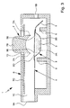
- Fig. 1 schematically shows the structure of a proposed inhaler 1 according to a first embodiment.
- the inhaler 1 is preferably designed to be portable and / or works in particular only mechanically.
- the inhaler 1 is used for dispensing or inhaling a preferably powdered formulation 2 in the sense mentioned above.
- Formulation 2 is preferably pre-dosed in a single dose or multiple doses.
- the formulation 2 is preferably pre-dosed, ie predosed outside the inhaler 1 already in a single dose or in several doses. In principle, however, it is also possible to dose the formulation 2 only immediately before each inhalation and / or in the inhaler 1.
- a carrier 3 carries the formulation 2 or provides them.
- the carrier 3 has at least one depression or receptacle 3A or the like for receiving in particular one dose of the formulation 2.
- the formulation 2 may be arranged or distributed on the surface or in a region of the surface or on the entire surface of the carrier 3.
- the carrier 3 is in particular flexible, flat, band-shaped, strip-shaped, blister-like and / or foil-like. It is made of a suitable material, in particular of plastic, metal foil, a composite material o. The like., Made or constructed.
- the carrier 3 can have only one receptacle 3A or several receptacles 3A. Each receptacle 3A may require an optional 3D cover as needed, as shown in FIG FIG. 1 indicated by way of example.
- the cover 3D is then preferably openable, peelable or the like.
- the cover 3D can be cut open, torn, perforated or otherwise at least partially removed and / or opened to allow a discharge of formulation 2.
- the opening is carried out by an associated opening device 7, if necessary. Only when moving the carrier 3. The opening device will be discussed later.
- the cover 3D and / or one or more relatively small outlet openings, openings or holes 3E (see Fig. 5 ) or the like leads or particularly preferably result in that the formulation 2 is released and discharged relatively slowly, in particular at a desired rate.
- the carrier 3 is, as in Fig. 1 indicated schematically, preferably formed blister-like.
- the carrier 3 has a carrier element or bottom element 3B which in particular has a depression or is deep-drawn to form the receptacle 3A or a receiving space for the formulation 2.
- the receiving space or the receptacle 3A is preferably covered by the cover 3D.
- the carrier element or bottom element 3B is formed by a foil or a foil material or composite material.
- the cover 3D is preferably sealed or laminated on the carrier element or bottom element 3B.
- the cover 3D is particularly preferably formed by a thin film, for example made of plastic, aluminum, a composite material or the like.
- the carrier 3 or its carrier element / bottom element 3 B and cover 3D forms a blister or a blister pack.
- the inhaler 1 is preferably designed in the illustrated embodiment as a disposable inhaler and / or for dispensing or administering only one dose. However, in principle it can also be a reusable inhaler, which is preferably used for independent dispensing of multiple doses of the formulation or different formulations is formed.
- the carrier 3 can have a plurality of independent openable receptacles 3A, and / or finger-like projections, each having a receptacle 3A.
- the various receptacles 3A and / or finger regions can be connected to one another or in particular in an end region such that the finger regions or receptacles 3A can be set into oscillation independently of one another.
- the carrier 3 is then movable, for example transversely to the flow direction and / or direction of vibration or pulled by the inhaler 1, in particular to change from a recording 3A to the next recording 3A or to bring the next finger area in a position to the proposed swinging and dispensing the respective dose from the respective receptacle 3A.
- the inhaler 1 preferably has at least one carrier 3 or is designed to accommodate at least one carrier 3.
- the carrier 3 may also have a plurality of receptacles 3A for a plurality of cans, possibly also for cans of different formulations 2.
- a plurality of receptacles 3A for a plurality of cans, possibly also for cans of different formulations 2.
- the carrier 3 is preferably held or arranged fixed in the inhaler 1 and / or not changeable.
- the inhaler 1 therefore preferably has a carrier 3 in the illustrated embodiment.
- the carrier 3 is preferably held movably via a spring section 4.
- the carrier 3 is at least substantially transversely or perpendicular to its surface extension movably held by the spring portion 4.
- the spring portion 4 to the vibration of the carrier 3 is elastically deformable.
- the carrier 3 may be formed elastically deformable.
- the carrier 3 or its carrier element or bottom element 3B is preferably formed at least substantially flat or by a main surface extension (in the illustration according to FIG Fig. 1 horizontal and perpendicular to the plane or by a plane parallel to the section plane II-II of Fig.1 characterized)
- the spring portion 4 preferably extends at least substantially in the main plane of extension of the carrier 3 or in a plane parallel thereto.
- the spring section 4 forms a (virtual) axis A (cf. Fig. 2 ), around which the carrier 3 in particular can move in rotation.
- the carrier 3 is guided or held by the spring section 4.
- the axis A is not fixed, but may in particular in the plane of the spring portion 4 (in particular depending on the material and shape of the spring portion 4) vary or migrate and / or move translationally in other levels.
- the spring section 4 is in particular due to the preferred structure in particular designed such that the axis A is not tilted, but shifts only parallel.
- the spring portion 4 is preferably at least substantially web-like or sheet-like.
- the spring portion 4 is preferably formed at least substantially band-shaped and / or film-like.
- the spring portion 4 preferably has two spring portions or webs 4A and / or at least one opening, preferably a particular slot or longitudinal slot 4B arranged therebetween. Experiments have shown that such a very defined spring and bending behavior can be achieved. This is very conducive to a defined output of the formulation 2 and movement, amplitude and / or frequency of the carrier 3.
- the size of the opening is at least 10%, in particular about 20% or more of the total area of the spring section 4 and / or less than 70%, particularly preferably less than 50% of the total area of the spring section 4.
- the opening is preferably slot-shaped.
- the opening may also have any other shape.
- a plurality of apertures can also be provided.
- the spring section 4 can be formed by a separate piece of material or, as indicated in the first embodiment, by the carrier element or bottom element 3B of the carrier 3.
- the spring portion 4 may be formed integrally with the carrier 3 and / or be made of the same material.
- the material in the region of the spring section 4 can also be made thinner and / or drawn for better elasticity, for example.
- the elasticity of the spring section 4 can also be influenced or determined by a corresponding arrangement and / or size of the opening 3.
- the preferably leaf-shaped spring section 4 may also be made of a different material, for example an elastic plastic, in particular polycarbonate, or of metallic spring plate.
- the carrier 3 is connected to the spring portion 4, preferably by gluing or welding, but also injection-molding or over-molding for connection is possible. In general, the connection can be made in any suitable manner.
- the spring section 4 is preferably fixedly mounted or held on the inhaler 1 or a housing 6 of the inhaler 1 at one end in the illustrated example, preferably by gluing, welding Pinching or the like.
- the carrier 3 preferably connects-in particular in extension-on.
- the carrier 3 is associated with a wing 5, as in Fig. 1 and 2 indicated.
- the wing 5 is preferably arranged on the spring section 4 opposite end or free end of the carrier 3.
- the wing 5 is preferably inclined to the surface extension of the carrier 3 and / or the direction of the incoming air flow L.
- the inclination of the blade 5 to the surface extension of the carrier 3 or to the air flow is preferably at least substantially 30 ° to 70 °, in particular substantially 40 ° to 50 °, very particularly preferably substantially 45 °.
- the wing 5 is preferably formed integrally with the carrier 3 or formed by the (same) carrier material, in particular by appropriate deformation.
- the wing 5 may be made of another material or piece of material, such as a spring plate, which is fixed to the carrier 3.
- a soft or rounded transition in particular with a radius of at least 1 to 2 mm, between the support 3 and the wing 5 is provided.
- the wing 5 is preferably as close as possible to the receptacle 3A, that is, in particular, immediately adjacent to this, arranged.
- the support 3 is movable by means of the air flow L for discharging the formulation 2, ie for releasing the formulation 2 from the support 3 or from the receptacle 3A, in particular in vibration.
- the air flow L can act directly and / or indirectly on the carrier 3 or move it.
- the spring portion 4 is preferably deformed resiliently.
- the spring section 4 oscillates.
- the air flow L also forms a conveying medium in order to disperse and / or convey the formulation 2 dissolved by the carrier 3, in particular by its movement, and preferably via a mouthpiece or an outlet 1A of the inhaler 1 to be dispensed to a user, not shown,
- a delivery medium for the formulation 2 a different or separate air flow or other air in the aforementioned sense - including other gas - are used.
- the air flow L is preferably generated by inhaling or inhaling the user, not shown, in particular by sucking in ambient air.
- the aspirated or in the inhaler 1 or its housing 6 through the inlet 1B incoming airflow L preferably first meets the inclined wing 5.
- the optional wing 5 can support the preferred transverse movement or vibration S of the carrier 3 caused by the air flow L. or cause.
- the carrier 3 is deflected by the air flow L and set in oscillation S.
- the movement level runs according to the illustration Fig. 1 preferably in the drawing plane.
- the carrier 3 thereby carries out a rotary or pivoting movement, guided by the spring section 4 or about the axis A (FIG. Fig. 2 ) out,
- the inhaler 1 preferably has the opening device 7.
- the opening device 7 is designed in particular for piercing the cover 3D.
- the opening device 7 preferably has at least one piercing element 7A.
- the opening device 7 or the piercing element 7A is preferably formed by or arranged on a wall region of the inhaler 1 or the housing 6 of the inhaler 1, in particular an upper part 6B of the housing 6.
- the opening device 7 or the piercing element 7A or the wall region can be pressed in manually, so that the cover element 7A, the cover 3D can pierce, this piercing example in the in Fig. 1 shown initial or center position of the carrier 3 and / or upon deflection of the carrier 3, for example in an end position in which the carrier 3 or its bottom element 3B abuts, for example, on an opposite stop 9, can take place.
- the receptacle 3A or cover 3D can be opened solely by the movement or oscillation of the carrier 3.
- the wall area must not be flexible.
- the opening device 7 or its piercing element 7A is then preferably arranged such that a piercing takes place automatically when the carrier 3 vibrates accordingly.
- the formulation 2 After opening the receptacle 3A or the cover 3D, the formulation 2 is discharged by the movement and / or the air flow L during further oscillation of the carrier 3. Depending on the opening of the cover 3D, the air flow L can also flow through the receptacle 3A in order to discharge the formulation 2.
- the air flow L entrains the powder, so that a powder-laden air flow P is produced, as shown schematically in FIG Fig. 1 indicated.
- the airflow L or powder-laden airflow P preferably flows at least substantially on a flat side, here the upper flat side or cover-side flat side of the carrier 3 or the flat 2 de delivering the formulation 2 carrier 3 or along.
- the powder-laden air flow P may preferably at least substantially rectilinearly flow to the outlet 1A of the inhaler 1 and be dispensed above it to a user, not shown.
- the housing 6 of the inhaler 1 is preferably constructed in the illustrated example of the lower part 6A and the upper part 6B or two halves or parts. Particularly preferably, the housing 6 is constructed in two parts or two shells or from two half shells. The two parts or the lower part 6A and the upper part 6B are preferably snapped together, glued, welded and / or joined together in any other suitable manner. Alternatively, the housing 6 or these parts 6A, 6B can also be formed integrally or formed by a collapsible part, which is particularly preferably produced in a plastic injection molding process. However, other constructive solutions are possible.
- the inhaler 1, the housing 6 and / or the support 3 or the receptacle 3A is or are preferably-at least partially-transparent. Thus, a user can easily recognize whether the inhaler 1 has already been used or emptied or can still be used.
- the inhaler 1 has a mouthpiece, which is preferably formed in the illustrated embodiment by the housing 6 and / or in the region of the outlet 1A. Accordingly, the unillustrated user may preferably take the inhaler 1 directly into the mouth and inhale to suck in ambient air and generate the airflow L.
- the inhaler 1 is preferably designed such that at an air flow L of 70 1 / min. a pressure drop of about 3 to 5 kPa, more preferably of substantially 4 kPa occurs.
- the inhaler 1 is preferably designed for a volume flow of about 20 to 100 l / min.
- the inhaler 1 is preferably designed such that the frequency of the oscillation is at least substantially 50 to 100 Hz, particularly preferably 60 to 90 Hz and very particularly preferably substantially 70 to 80 Hz, in particular at a volume flow of 20 to 100 l / minute particularly preferably at a volume flow of substantially 70 l / min.
- the frequency of the oscillation depends in particular on the filling quantity or the filling weight.
- the filling amount of the receptacle 3A is selected so that a desired frequency is achieved. Starting from a certain dose or amount of active ingredient, for example, to increase the weight of the formulation, an additional substance or a greater proportion of a particular substance may be added to affect the frequency.
- the inhaler 1 is preferably designed such that the amplitude of the oscillation is at least 1 mm, in particular substantially 2 mm, and / or less than 10 mm, preferably less than 6 mm, in particular less than 4 mm.
- the inlet 1B for the air or the air flow L is preferably arranged on the side opposite the outlet 1A and / or adjacent to the free end of the carrier 3 or to the wing 5.
- the direction of the airflow L flowing through the inlet 1B when impinging on the support 3 or wing 5 is at least substantially parallel to the main flow direction of the powder-laden air flow P or to the main exit direction or main discharge direction of the inhaler 1, ie in the illustration according to FIG Fig. 1 at least substantially horizontally.
- the air inlet 1B is preferably formed between or from the two housing parts 6A and 6B.
- the inhaler 1 or its housing 6 preferably forms a flow space 1C, which extends at least substantially paragraph-free and / or rectilinearly from the carrier 3 or its receptacle 3A to the outlet 1A, wherein the cross section of the flow space 1C, in particular towards the outlet 1A, in the illustration example, parallel to the main extension direction or areal extent of the carrier 3, as in FIG Fig. 2 indicated to form a mouthpiece or a mouthpiece area on the outlet side.
- a flow space 1C which extends at least substantially paragraph-free and / or rectilinearly from the carrier 3 or its receptacle 3A to the outlet 1A, wherein the cross section of the flow space 1C, in particular towards the outlet 1A, in the illustration example, parallel to the main extension direction or areal extent of the carrier 3, as in FIG Fig. 2 indicated to form a mouthpiece or a mouthpiece area on the outlet side.
- FIG Fig. 2 indicated to form a mouthpiece or a mouthpiece area on the outlet
- the carrier 3 is at least substantially only in the region of its free end and / or flowed only on a flat side.
- the inhaler 1 preferably has at least one, in the illustrated example, two or more stops 8 and 9, as in FIG Fig. 1 shown.
- the stops 8 and 9 are preferably formed in the illustrated embodiment of the housing 6 and its wall. However, other constructive solutions are possible.
- the stops 8 and 9 limit the amplitude or deflection of the carrier 3 during swinging. This is a defined swinging and thus a defined discharge of the formulation 2 beneficial.
- the carrier 3 or its carrier element or bottom element 3B is preferably formed or constructed from a composite material of aluminum, polyamide, PVC and sealing wax or the like.
- the spring portion 4 may be made of the same material or another material. Particularly preferably, the spring section 4 is made of an elastic plastic, in particular polycarbonate.
- the carrier 3 or the receptacle 3A has a particularly or at least substantially angular transition of the edge 3C of the carrier element or bottom element 3B to the cover 3D, as in FIG Fig. 1 indicated schematically.
- an acute gusset is avoided in this area because otherwise there, the formulation 2 can settle or set in an undesirable manner.
- the preferred at least substantially rectangular transition from the side wall or edge 3C to the cover 3D can counteract such setting namely namely and / or is at least substantially complete discharge of the formulation 2 beneficial.
- the carrier 3 or its carrier element or bottom element 3B is produced from a thicker foil, from composite material or the like by hot embossing, blow molding or deep drawing.
- production by plastic injection molding is preferred.
- the carrier 3 can have, for example, a plurality of receptacles 3A with possibly different formulations 2.
- a preferably parallel arrangement of the receptacles 3A is preferred, so that at least substantially equal vibrations or vibration properties are achieved.
- other configurations are possible.
- the preferably provided dispersing method (movement of the carrier 3 or the opened or opening receptacle 3A in the air stream L for dispensing and dispersion of the formulation 2 in the air stream L) has various advantages. It is a very uniform dispersion with good Deagglomaration of the particles of preferably powdered Formulation 2 allows. It allows a relative volume flow independence. In particular, the dispensing movement or vibration or oscillation, and thus the dispensing of the formulation 2, preferably only starts at a flow rate or a flow rate of 10 or 20 l / min. Furthermore, a perceptible audible signal to the user by the swing - ie when inhaling - are generated.
- Fig. 3 shows a second embodiment of the proposed inhaler 1 in a schematic section similar to Fig. 1 ,
- the stops 8 and 9 are preferably arranged only on one side.
- perforations, openings or holes 3E in the cover 3D which are successive in the flow direction, can preferably be produced in the cover 3D.
- the opening device 2 namely in the flow direction one behind the other or more piercing elements 7A.
- the opening device 7 is thus preferably designed to produce a plurality of openings or holes 3E. This is a particularly good emptying of the support 3 and the recording 3A or a good or complete discharge of the formulation 2 beneficial.
- the opening device 7 preferably has an actuating element 7B for the manual actuation of the opening device 7.
- the inhaler 1 or the housing 6 preferably has an opening 1D, through which the actuating element 7B extends to the outside.
- the opening device 7 can be actuated and the carrier 3 or the cover 3D can be opened or pierced by means of the piercing elements 7A.
- the opening device 7 has a spring element 7C, that the at least one piercing element 7A and the actuating element 7B resiliently holds, in particular in the Fig. 3 shown starting position from which the piercing elements 7A by pressing on the actuating element 7B from the outside in a direction to the carrier 3 towards advanced position (in Fig. 3 down) is movable.
- a preferably elastic return by the spring element 7C ensures that the starting position is taken again and in particular the opening 1D is closed again.
- the spring section 4 is made of a different material or piece of material than the carrier 3 or its carrier element 3A or bottom element 3B.
- the wing 5 may also be made of a different material or piece of material.
- the wing 5 is then preferably still connected in a suitable manner to the carrier or its carrier element or bottom element 3B.
- Fig. 4 shows the proposed inhaler 1 in one Fig. 1 corresponding schematic section with a closed or covered by a covering 10 carrier.
- Fig. 5 shows the inhaler 1 in a corresponding section, but with the covering device 10 removed.
- the inhaler 1 preferably has the cover 10 to cover the receptacle 3A and its cover 3D, respectively.
- the covering device 10 or a covering element 10A of the covering device 10 can be pulled off or removed to open the receptacle 3A or one or more apertures or holes 3E of the cover 3D.
- the covering device 10 particularly preferably has a covering element 10A, in particular a foil-like covering, which covers the carrier 3 or the receptacle 3A or the cover 3D or apertures or holes 3E provided in the cover 3D, as in FIG Fig. 4 indicated schematically. Fig. 4 So it shows the locked state.
- a covering element 10A in particular a foil-like covering, which covers the carrier 3 or the receptacle 3A or the cover 3D or apertures or holes 3E provided in the cover 3D, as in FIG Fig. 4 indicated schematically. Fig. 4 So it shows the locked state.
- the cover element 10A is preferably folded over, folded over or folded over.
- the cover element 10A and / or an optionally arranged thereon grip element 10B of the cover 10 preferably protrudes from the inhaler 1 and its housing 6, in particular from the outlet 1A out.
- the cover member 10A By pulling on the cover member 10A or handle member 10B, the cover member 10A may preferably be peeled off. This is particularly easy due to the folding, since the cover 10A In the area of the bend or folding when pulling pulls quasi and thus relatively easily from the support 3 and the cover 3D triggers or subtracts.
- the grip element 10B or the cover element 10A preferably has a color or signal color which is easily recognizable to the user, in particular red. Accordingly, it is intuitively clear to the user that he must first pull on it, ie, first remove the cover element 10A before he can use the inhaler 1.
- the receptacle 3A or the openings or holes 3E are open, as in FIG Fig. 5 shown so that the inhaler 1 can be used directly.
- the cover 3D only has a hole 3E, this is preferably arranged in the vicinity of the wing 5. In the case of two or more holes 3, these are preferably arranged in opposite end regions in the longitudinal direction or air flow direction.
- the inhaler 1 or carrier 3 or the cover 3D preferably has a plurality of perforations or holes 3E, particularly preferably 3 to 5 perforations or holes 3E.
- the openings or holes 3E are preferably round and / or preferably have a diameter of 0.5 to 3 mm, in particular substantially 1.0 to 2.7 mm, very particularly preferably of about 1.5 mm.
- the holes 3E need not be round, but may have any other shape, for example, be triangular, in particular suitable for the respective opening mechanism or adapted to the shape of the receptacle 3A.
- predetermined or defined, in particular proposals designed openings or holes 3E is a defined Deagglomeration and issue, ie atomization, the formulation 2 or the powder particles of the formulation 2 beneficial.
- cover 3D with the holes 3E may be formed from any active ingredient-compatible material, depending on the application, in particular made of plastic, paper or the like, if appropriate also of metal or metal foil.
- the cover 3D may also be designed as an insert, for example by a grid-like element or the like inserted into the receptacle 3, and / or form an assembly with the cover element 10A.
- the cover 3D and the cover 10A are formed by two superimposed films or layers, in particular wherein the cover 3D contains the hole structure and the cover 10A is used for moisture protection of the formulation 2 in the unopened state.
- the sealing of the receiving space or the receptacle 3A for the formulation 2 against moisture is then preferably taken over by a cover film, in this case in particular by the covering element 10A.
- the entire inhaler 1 can be protected against moisture, for example by an outer envelope, not shown, foil packaging o.
- the illustrated inhaler 1 is preferably designed as a disposable inhaler for single use.
- the inhaler 1 (regardless of the design of the cover 3D or regardless of the opening by piercing or pulling) in principle also be designed for multiple use.
- the carrier 3 is changeable.
- the inhaler 1 can optionally also contain a plurality of carriers 3 and / or holders 3A which can be opened individually or independently of one another in order to be able to dispense one or more doses of the formulation 2 individually or independently of one another.
- Individual features and aspects of the various embodiments can also be arbitrarily combined with each other, but also realized independently or used in other designs of inhalers.
- inhaler is to be understood in a broader sense also as meaning that it also comprises other dispensers or atomizers, in particular for medical or other therapeutic purposes,
Landscapes
- Health & Medical Sciences (AREA)
- Engineering & Computer Science (AREA)
- Bioinformatics & Cheminformatics (AREA)
- Pulmonology (AREA)
- Anesthesiology (AREA)
- Biomedical Technology (AREA)
- Heart & Thoracic Surgery (AREA)
- Hematology (AREA)
- Life Sciences & Earth Sciences (AREA)
- Animal Behavior & Ethology (AREA)
- General Health & Medical Sciences (AREA)
- Public Health (AREA)
- Veterinary Medicine (AREA)
- Medicinal Preparation (AREA)
- Containers And Packaging Bodies Having A Special Means To Remove Contents (AREA)
- Medical Preparation Storing Or Oral Administration Devices (AREA)
Abstract
Description
- Die vorliegende Erfindung betrifft einen Inhalator gemäß dem Oberbegriff des Anspruchs 1 sowie ein Verfahren zur Ausgabe und insbesondere Zerstäubung einer vorzugsweise pulverförmigen Formulierung von einem Träger gemäß dem Oberbegriff des Anspruchs 15.
- Die vorliegende Erfindung betrifft insbesondere einen Inhalator zur Ausgabe bzw. Inhalation einer vorzugsweise pulverförmigen Formulierung, also einen Pulverinhalator. Jedoch kann die Formulierung grundsätzlich auch in flüssiger Phase, als Dispersion oder in sonstiger fluidisierbarer Form vorliegen.
- Bei der Formulierung handelt es sich insbesondere um ein therapeutisches Mittel bzw. Arzneimittel. Insbesondere enthält die Formulierung dementsprechend mindestens einen Wirkstoff oder besteht daraus. Die Formulierung dient also insbesondere der medizinischen Behandlung oder sonstigen therapeutischen Zwecken.
- Bei der vorliegenden Erfindung ist die Formulierung in oder von einem Träger aufgenommen, insbesondere vordosiert in einzelnen Dosen.
- Die
WO 2008/034504 A2 , die den Ausgangspunkt der vorliegenden Erfindung bildet, offenbart einen Inhalator zur Inhalation einer Formulierung von einem Träger, wobei zum oder beim Austrag und/oder Dispergieren der Formulierung zumindest ein Teil des Trägers durch einen Luftstrom in Schwingung versetzt wird. Der Träger ist insbesondere flach, blisterartig und/oder folienartig ausgebildet.Fig. 3 derWO 2008/034504 A2 zeigt eine Ausführungsform, bei der der Träger direkt vom Luftstrom bewegt bzw. in Schwingung versetzt wird. Problematisch ist, dass der Träger quer zu seiner Flachseite angeströmt wird und frei flattert. - Der vorliegenden Erfindung liegt die Aufgabe zugrunde, einen verbesserten Inhalator und ein verbessertes Verfahren anzugeben, so dass auf einfache Weise eine effektive Ausbringung und insbesondere Zerstäubung einer insbesondere pulverförmigen Formulierung ermöglicht wird und/oder ein einfacher und/oder kostengünstiger Aufbau, insbesondere als Einweginhalator, ermöglicht wird.
- Die obige Aufgabe wird durch einen Inhalator gemäß Anspruch 1 oder durch ein Verfahren gemäß Anspruch 15 gelöst. Vorteilhafte Weiterbildungen sind Gegenstand der Unteransprüche.
- Vorschlagsgemäß weist der Inhalator einen durch einen Luftstrom insbesondere direkt bewegbaren bzw. in Schwingung versetzbaren Träger auf. Besonders bevorzugt weist der Träger eine die Formulierung enthaltende Aufnahme auf. Alternativ kann der Träger auch mehrere, vorzugsweise zwei Aufnahmen, insbesondere mit unterschiedlichen Formulierungen, aufweisen.
- Der Träger ist vorzugsweise mittels eines Federabschnitts beweglich gehalten. Der Träger ist vorzugsweise unmittelbar durch einen Luftstrom zum Austrag und/oder Dispergieren der Formulierung(en) bewegbar, insbesondere in Schwingung versetzbar.
- Ein Aspekt der vorliegenden Erfindung liegt darin, dass der Träger definiert in Schwingung versetzbar ist bzw. schwingt, insbesondere mit einer definierten Bewegung, mit einer definierten Amplitude und/oder mit einer definierten Frequenz. Dies ist einer verbesserten und definierten Ausgabe und Zerstäubung bzw. Dispergierung zuträglich.
- Vorzugsweise ist unter einer "definierten Bewegung" eine über nur gewisse bzw. bestimmte Freiheitsgrade aufweisende Bewegung zu verstehen. Besonders bevorzugt ist der Träger zumindest im Wesentlichen nur um eine bestimmte bzw. von dem Federabschnitt gebildete Achse bzw. rotatorisch bzw. nur in Form einer Schwenkbewegung bewegbar, insbesondere wobei die Bewegungsbahn des Trägers in einer Ebene liegt und eine Haupterstreckungsebene des flachen Trägers zumindest im Wesentlichen immer senkrecht zu dieser Bewegungsebene verläuft.
- Unter dem Begriff "definierte Amplitude" ist vorzugsweise eine Begrenzung der Bewegung bzw. Amplitude des Trägers zu verstehen, wobei hierzu bedarfsweise auch eine nur einseitige, also nur in einer Bewegungsrichtung wirkende Begrenzung, beispielsweise durch einen Anschlag, vorgesehen sein kann.
- Unter dem Begriff "definierte Frequenz" ist vorzugsweise eine beschränkte Frequenz oder ein beschränkter Frequenzbereich zu verstehen, mit dem der Träger bei Benutzung schwingt. Da bei der Benutzung, insbesondere wenn der Luftstrom durch das Einatmen eines Benutzers erzeugt wird, unterschiedliche Luftströme auftreten können, ist der bestimmte Frequenzbereich der Schwingung vorzugsweise in Abhängigkeit von einem bestimmten Volumenstrom oder einem bestimmten Volumenstrombereich zu verstehen.
- Der Träger bzw. Federabschnitt ist vorzugsweise nur an einer Seite fixiert oder gehalten, insbesondere eingespannt oder befestigt. Der Träger bzw. Federabschnitt endet an der anderen Seite frei bzw. so, dass die andere Seite (frei) schwingen kann.
- Ein anderer Aspekt der vorliegenden Erfindung liegt darin, dass der Federabschnitt den Träger quer zum Luftstrom vorzugsweise beweglich, aber in Richtung des Luftstroms zumindest im Wesentlichen torsionssteif hält. Dies ist einer definierten Bewegung, Amplitude und/oder Frequenz des Träges zuträglich.
- Gemäß einem anderen Aspekt der vorliegenden Erfindung weist der Federabschnitt vorzugsweise zwei parallel verlaufende Federstege und/oder eine Durchbrechung, insbesondere einen Längsschlitz, auf. Dies ist einer definierten Bewegung, Amplitude und/oder des Trägers zuträglich.
- Gemäß einem anderen Aspekt der vorliegenden Erfindung ist der Träger zumindest im Wesentlichen ausschließlich von einem freien bzw. dem Federabschnitt entgegen gesetzten Ende her vom Luftstrom anströmbar. Dies ist einem optimalen Austrag der Formulierung zuträglich, insbesondere da unnötige Verwirbelungen im Inhalator vermieden oder minimiert werden können. Alternativ oder zusätzlich ist dies einer definierten Schwingung des Trägers zuträglich.
- Gemäß einem weiteren Aspekt der vorliegenden Erfindung ist dem Träger vorzugsweise ein schrägstehender, vom Luftstrom anströmbarer Flügel zugeordnet. Besonders bevorzugt ist der Flügel an einem freien Ende des Trägers und/oder benachbart zu einem Lufteinlass des Inhalators angeordnet. Dies gestattet einen kompakten Aufbau und ein definiertes Anströmen des Trägers und/oder ein effizientes Einwirken auf den Träger, um diesen in Schwingung zu versetzen.
- Gemäß einem weiteren Aspekt der vorliegenden Erfindung ist der Träger oder eine Abdeckung des Trägers vorzugsweise zumindest partiell durch eine Abdeckeinrichtung abgedeckt, die zum Öffnen des Trägers bzw. der Abdeckung für eine anschließende Ausgabe der Formulierung manuell öffenbar oder entfernbar ist. Besonders bevorzugt erfolgt das Öffnen oder Entfernen der Abdcckeinrichtung durch Ziehen an einem Griffelement oder Abdeckelement der Abdeckeinrichtung. Hierdurch können besonders bevorzugt in der Abdeckung bereits befindliche Durchbrechungen, Öffnungen oder Löcher freigelegt werden. Dies ist einer definierten Abgabe und Zerstäubung der Formulierung zuträglich.
- Die Formulierung kann vorschlagsgemäß besonders wirkungsvoll insbesondere aus einer entsprechenden Aufnahme des Trägers ausgegeben, dispergiert und/oder ausgetragen werden.
- Zum Austrag der Formulierung kann wahlweise der Luftstrom zum Bewegen des Trägers oder ein sonstiger Luftstrom eingesetzt werden.
- Bei der vorliegenden Erfindung sind die Begriffe "Luft" und "Luftstrom" vorzugsweise in einem weiteren Sinne auch dahingehend zu verstehen, dass auch ein sonstiges Gas bzw. eine Strömung eines sonstigen Gases umfasst ist. Nachfolgend wird jedoch immer der Begriff "Luft" verwendet, da üblicherweise Luft als Gas zum Antrieb bzw. zur Bewegung des Trägers und/oder als Fördermedium zur Förderung der Formulierung nach dem Lösen von oder aus dem Träger bzw. zum Dispergieren der Formulierung eingesetzt wird. Vorzugsweise wird der Luftstrom beim Inhalieren bzw. durch ein Einatmen erzeugt. Es handelt sich also insbesondere um einen passiven Inhalator.
- Besonders bevorzugt ist der Inhalator zur Ausgabe bzw. Verabreichung oder Inhalation lediglich einer Einzeldosis ausgebildet. Besonders bevorzugt handelt es sich also um ein Einweggerät. Jedoch kann der Inhalator alternativ auch zur mehrfachen Verwendung und/oder zur getrennten Ausgabe mehrerer Dosen der Formulierung ausgebildet sein. Beispielsweise sind dann mehrere Aufnahmen vorgesehen, die unabhängig voneinander öffenbar sind.
- Die vorgenannten Aspekte und die sich aus der weiteren Beschreibung und den Ansprüchen ergebenden Aspekte können auch unabhängig voneinander, aber auch in beliebiger Kombination realisiert werden.
- Einzelne Aspekte, Merkmale, Eigenschaften und Vorteile der vorliegenden Erfindung ergeben sich aus den Ansprüchen und der folgenden Beschreibung bevorzugter Ausführungsformen anhand der Zeichnung. Es zeigt:
- Fig. 1
- einen schematischen Schnitt eines vorschlagsgemäßen Inhalators gemäß einer ersten Ausführungsform;
- Fig. 2
- einen schematischen horizontalen Schnitt des Inhalators gemäß
Fig. 1 entlang Linie II-II; - Fig. 3
- einen schematischen Schnitt eines vorschlagsgemäßen Inhalators gemäß einer zweiten Ausführungsform;
- Fig. 4
- einen schematischen Schnitt eines vorschlagsgemäßen Inhalators gemäß einer dritten Ausführungsform mit verschlossener Abdeckung einer Aufnahme eines Trägers; und
- Fig. 5
- einen schematischen Schnitt des Inhalators gemäß
Fig. 4 mit geöffneter Abdeckung. - In den Figuren werden für gleiche oder ähnliche Teile die gleichen Bezugszeichen verwendet, auch wenn eine wiederholte Beschreibung weggelassen ist. Insbesondere ergeben sich dann auch die gleichen oder entsprechende Vorteile und Eigenschaften. Die einzelnen Figuren sind aus Darstellungs- oder Vereinfachungsgründen nicht maßstabsgerecht und auf wesentliche für die Erfindung relevante Komponenten reduziert,
-
Fig. 1 zeigt schematisch den Aufbau eines vorschlagsgemäßen Inhalators 1 gemäß einer ersten Ausführungsform. Der Inhalator 1 ist vorzugsweise tragbar ausgebildet und/oder arbeitet insbesondere nur mechanisch. - Der Inhalator 1 dient der Ausgabe bzw. Inhalation einer vorzugsweise pulverförmigen Formulierung 2 im eingangs genannten Sinne. Die Formulierung 2 ist vorzugsweise vordosiert in einer einzelnen Dosis oder mehrere Dosen.
- Beim Darstellungsbeispiel ist die Formulierung 2 vorzugsweise vordosiert, also außerhalb des Inhalators 1 bereits in einer einzelnen Dosis oder in mehrere Dosen vordosiert. Grundsätzlich ist es jedoch auch möglich, die Formulierung 2 erst unmittelbar vor jeder Inhalation und/oder im Inhalator 1 zu dosieren.
- Ein Träger 3 trägt die Formulierung 2 bzw. stellt diese bereit. Insbesondere weist der Träger 3 mindestens eine Vertiefung bzw. Aufnahme 3A o. dgl. zum Aufnehmen insbesondere einer Dosis der Formulierung 2 auf. Jedoch sind hier auch andere konstruktive Lösungen möglich. Beispielsweise kann die Formulierung 2 auf der Oberfläche oder in einem Bereich der Oberfläche oder auf der gesamten Oberfläche des Trägers 3 angeordnet oder verteilt sein.
- Der Träger 3 ist insbesondere flexibel, flach, bandförmig, streifenförmig, blisterartig und/oder folienartig ausgebildet. Er ist aus einem geeigneten Material, insbesondere aus Kunststoff, Metallfolie, einem Verbundmaterial o. dgl., hergestellt oder aufgebaut.
- Der Träger 3 kann nur eine Aufnahme 3A oder mehrere Aufnahmen 3A aufweisen. Jede Aufnahme 3A kann bedarfsweise von einer optionalen Abdeckung 3D, wie in
Figur 1 beispielhaft angedeutet, abgedeckt sein. Zum Austrag der Formulierung 2 ist die Abdeckung 3D dann vorzugsweise öffenbar, abziehbar oder dergleichen. Beispielsweise kann die Abdeckung 3D aufgeschnitten, aufgerissen, perforiert oder in sonstiger Weise zumindest teilweise entfernt und/oder geöffnet werden, um einen Austrag der Formulierung 2 zu ermöglichen. Besonders bevorzugt erfolgt das Öffnen durch eine zugeordnete Öffnungseinrichtung 7, ggfs. auch erst bei Bewegung des Trägers 3. Auf die Öffnungseinrichtung wird später noch eingegangen. - Die Abdeckung 3D und/oder eine oder mehrere verhältnismäßig kleine Austrittsöffnungen, Durchbrechungen oder Löcher 3E (siehe
Fig. 5 ) oder dergleichen führt bzw, führen besonders bevorzugt dazu, dass die Formulierung 2 verhältnismäßig langsam - insbesondere mit einer gewünschten Rate - abgegeben und ausgetragen wird. - Der Träger 3 ist, wie in
Fig. 1 schematisch angedeutet, vorzugsweise blisterartig ausgebildet. Insbesondere weist der Träger 3 ein Trägerelement bzw. Bodenelement 3B auf, das insbesondere eine Vertiefung aufweist bzw. tiefgezogen ist, um die Aufnahme 3A bzw. einen Aufnahmeraum für die Formulierung 2 zu bilden. Der Aufnahmeraum bzw. die Aufnahme 3A ist vorzugsweise von der Abdeckung 3D abgedeckt. - Insbesondere ist das Trägerelement bzw. Bodenelement 3B durch eine Folie oder ein Folienmaterial oder Verbundmaterial gebildet.
- Die Abdeckung 3D ist vorzugsweise auf das Trägerelement bzw. Bodenelement 3B aufgesiegelt oder auflaminiert.
- Besonders bevorzugt ist die Abdeckung 3D durch eine dünne Folie, beispielsweise aus Kunststoff, Aluminium, einem Verbundmaterial oder dgl. gebildet.
- Besonders bevorzugt bildet der Träger 3 bzw. dessen Trägerelement/Bodenelement 3B und Abdeckung 3D einen Blister oder eine Blisterverpackung.
- Der Inhalator 1 ist beim Darstellungsbeispiel vorzugsweise als Einweginhalator und/oder zur Ausgabe bzw. Verabreichung nur einer Dosis ausgebildet. Jedoch kann es sich grundsätzlich auch um einen Mehrweginhalator handeln, der vorzugsweise zur unabhängigen Ausgabe von mehreren Dosen der Formulierung oder verschiedener Formulierungen ausgebildet ist.
- Bei einer Ausbildung als Mehrweginhalator kann der Träger 3 mehrere unabhängige voneinander öffenbare Aufnahmen 3A, aufweisen und/oder fingerartige Vorsprünge mit jeweils einer Aufnahme 3A aufweisen. Die verschiedenen Aufnahmen 3A bzw. Fingerbereiche können insbesondere in einem Endbereich miteinander bzw. derart verbunden sein, dass die Fingerbereiche bzw. Aufnahmen 3A unabhängig voneinander in Schwingung versetzbar sind. Der Träger 3 ist dann beispielsweise quer zur Strömungsrichtung und/oder Schwingungsrichtung bewegbar oder durch den Inhalator 1 ziehbar, insbesondere um von einer Aufnahme 3A zur nächsten Aufnahme 3A zu wechseln bzw. um den jeweils nächsten Fingerbereich in eine Position zu bringen, um dass vorschlagsgemäße Schwingen und Ausbringen der jeweiligen Dosis aus der jeweiligen Aufnahme 3A zu ermöglichen.Der Inhalator 1 weist vorzugsweise mindestens einen Träger 3 auf oder ist zur Aufnahme mindestens eines Trägers 3 ausgebildet.
- Wie bereits erwähnt, kann der Träger 3 auch mehrere Aufnahmen 3A für mehrere Dosen, ggf. auch für Dosen verschiedener Formulierungen 2, aufweisen. So ist es beispielsweise möglich, zwei unterschiedliche Formulierungen 2, die in unterschiedlichen Aufnahmen 3A bereitgehalten werden, gemeinsam über den Luftstrom L auszutragen und dabei ggf. zu mischen und/oder zumindest gleichzeitig oder ggf. auch zeitlich nacheinander einem Patienten beim Inhalieren zuzuführen.
- Beim Darstellungsbeispiel ist der Träger 3 vorzugsweise fest im Inhalator 1 gehalten oder angeordnet und/oder nicht wechselbar. Der Inhalator 1 weist daher beim Darstellungsbeispiel vorzugsweise einen Träger 3 auf.
- Der Träger 3 ist vorzugsweise über einen Federabschnitt 4 beweglich gehalten. Insbesondere ist der Träger 3 zumindest im Wesentlichen quer oder senkrecht zu seiner Flächenerstreckung beweglich vom Federabschnitt 4 gehalten. Besonders bevorzugt ist der Federabschnitt 4 zur Schwingung des Trägers 3 federelastisch verformbar. Alternativ oder zusätzlich kann auch der Träger 3 federelastisch verformbar ausgebildet sein.
- Der Träger 3 bzw. dessen Trägerelement oder Bodenelement 3B ist vorzugsweise zumindest im Wesentlichen flach ausgebildet oder durch eine Hauptflächenerstreckung (bei der Darstellung gemäß
Fig. 1 horizontal und senkrecht zur Zeichenebene bzw. durch eine Ebene parallel zur Schnittebene II-II vonFig.1 ) charakterisiert, - Der Federabschnitt 4 erstreckt sich vorzugsweise zumindest im Wesentlichen in der Haupterstreckungsebene des Trägers 3 oder in einer dazu parallelen Ebene.
- Besonders bevorzugt bildet der Federabschnitt 4 eine (virtuelle) Achse A (vgl.
Fig. 2 ), um die sich der Träger 3 insbesondere rotatorisch bewegen kann. Hierbei wir der Träger 3 von dem Federabschnitt 4 geführt bzw. gehalten. Die Achse A liegt dabei nicht fest, sondern kann insbesondere in der Ebene des Federabschnitts 4 (insbesondere je nach Material und Form des Federabschnitts 4) variieren oder wandern und/oder sich auch in anderen Ebenen translatorisch bewegen. Der Federabschnitt 4 ist insbesondere aufgrund des bevorzugten Aufbaus insbesondere derart ausgebildet, dass die Achse A nicht verkippt, sondern sich nur parallel verschiebt. - Der Federabschnitt 4 ist vorzugsweise zumindest im Wesentlichen stegartig oder blattartig ausgebildet. Der Federabschnitt 4 ist vorzugsweise zumindest im Wesentlichen bandförmig und/oder folienartig ausgebildet.
- Dem Horizontalschnitt gemäß
Fig. 2 ist zu entnehmen, dass der Federabschnitt 4 vorzugsweise zwei Federbereiche oder -stege 4A und/oder mindestens eine Durchbrechung, vorzugsweise einen insbesondere dazwischen angeordneten Schlitz bzw. Längsschlitz 4B aufweist. Versuche haben gezeigt, dass sich so ein sehr definiertes Feder- und Biegeverhalten erreichen lässt. Dies ist einer definierten Ausgabe der Formulierung 2 und Bewegung, Amplitude und/oder Frequenz des Trägers 3 sehr zuträglich. - Weiter verhindert die Durchbrechung, dass der Federabschnitt 4 und Träger 3 bei Erreichen einer Endlage den Strömungsweg ventilartig verschließen können. Vielmehr kann durch die Durchbrechung dann weiter Luft strömen. Vorzugsweise beträgt die Größe der Durchbrechung mindestens 10%, insbesondere etwa 20% oder mehr der Gesamtfläche des Federabschnitts 4 und/oder weniger als 70%, besonders bevorzugt weniger als 50% der Gesamtfläche des Federabschnitts 4.
- Beim Darstellungsbeispiel ist die Durchbrechung vorzugsweise schlitzartig ausgebildet. Jedoch kann die Durchbrechung auch jede sonstige Form aufweisen.
- Weiter können auch mehrere Durchbrechungen vorgesehen sein.
- Der Federabschnitt 4 kann von einem separaten Materialstück oder, wie bei der ersten Ausführungsform angedeutet, von dem Trägerelement bzw. Bodenelement 3B des Trägers 3 gebildet sein.
- Der Federabschnitt 4 kann einstückig mit dem Träger 3 ausgebildet und/oder aus dem gleichen Material hergestellt sein. Das Material im Bereich des Federabschnitts 4 kann zur besserem Elastizität beispielsweise auch dünner ausgebildet und/oder gezogen sein. Alternativ oder zusätzlich kann die Elastizität des Federabschnitts 4 auch durch entsprechende Anordnung und/oder Größe der Durchbrechung 3 beeinflusst oder festgelegt werden.
- Alternativ oder zusätzlich kann der vorzugsweise blattförmige Federabschnitt 4 auch aus einem anderen Material, beispielsweise einem elastischen Kunststoff, insbesondere Polycarbonat, oder aus metallischem Federblech hergestellt sein.
- Der Träger 3 ist mit dem Federabschnitt 4 vorzugsweise durch Kleben oder Schweißen verbunden, jedoch ist auch ein Anspritzen oder Überspritzen zum Verbinden möglich. Generell kann die Verbindung auf jede geeignete Art und Weise erfolgen.
- Der Federabschnitt 4 ist beim Darstellungsbeispiel an einem Ende vorzugsweise fest am Inhalator 1 oder einem Gehäuse 6 des Inhalators 1 angebracht oder gehalten, vorzugsweise durch Kleben, Schweißen Einklemmen oder dergleichen. Am anderen bzw. freien Ende des Federabschnitts 4 schließt sich vorzugsweise der Träger 3 - insbesondere in Verlängerung-an.
- Besonders bevorzugt ist dem Träger 3 ein Flügel 5 zugeordnet, wie in
Fig. 1 und2 angedeutet. Der Flügel 5 ist vorzugsweise an dem Federabschnitt 4 abgewandten Ende bzw. freien Ende des Trägers 3 angeordnet. - Der Flügel 5 ist vorzugsweise zu der Flächenerstreckung des Trägers 3 und/oder Richtung des anströmenden Luftstroms L geneigt. Die Neigung des Flügels 5 zu der Flächenerstreckung des Trägers 3 bzw. zur Luftströmung beträgt vorzugsweise zumindest im wesentlichen 30° bis 70° insbesondere im wesentlichen 40° bis 50°, ganz besonders bevorzugt im wesentlichen 45°.
- Der Flügel 5 ist vorzugsweise einstückig mit dem Träger 3 ausgebildet oder von dem (gleichen) Trägermaterial gebildet, insbesondere durch entsprechende Umformung. Alternativ kann der Flügel 5 auch aus einem sonstigen Material oder Materialstück, beispielsweise einem Federblech, hergestellt sein, das am Träger 3 befestigt ist.
- Vorzugsweise ist ein weicher oder gerundeter Übergang, insbesondere mit einem Radius von mindestens 1 bis 2 mm, zwischen dem Träger 3 und dem Flügel 5 vorgesehen.
- Der Flügel 5 ist vorzugsweise möglichst nahe an der Aufnahme 3A, insbesondere also unmittelbar benachbart zu dieser, angeordnet.
- Der Träger 3 ist mittels des Luftstroms L zum Austrag der Formulierung 2 - also zum Lösen der Formulierung 2 vom Träger 3 bzw. aus der Aufnahme 3A - bewegbar, insbesondere in Schwingung versetzbar. Der Luftstrom L kann unmittelbar und/oder mittelbar auf den Träger 3 einwirken bzw. diesen bewegen.
- Zur Schwingung des Trägers 3 wird der Federabschnitt 4 vorzugsweise federelastisch verformt. Insbesondere schwingt auch der Federabschnitt 4. Vorzugsweise bildet die Luftströmung L auch ein Fördermedium, um die vom Träger 3 insbesondere durch dessen Bewegung gelöste Formulierung 2 zu dispergieren und/oder zu fördern und vorzugsweise über ein Mundstück bzw. einen Auslass 1A des Inhalators 1 auszutragen und an einen nicht dargestellten Benutzer auszugeben, Jedoch kann als Fördermedium für die Formulierung 2 auch ein anderer bzw. getrennter Luftstrom bzw. sonstige Luft im eingangs genannten Sinne - also auch sonstiges Gas - eingesetzt werden.
- Beim Darstellungsbeispiel wird die Luftströmung L vorzugsweise durch das Inhalieren bzw. Einatmen des nicht dargestellten Benutzers erzeugt, und zwar insbesondere durch Ansaugen von Umgebungsluft.
- Der angesaugte bzw. in den Inhalator 1 bzw. dessen Gehäuse 6 durch den Einlass 1B einströmende Luftstrom L trifft vorzugsweise zuerst auf den schrägstehenden Flügel 5. Der optionale Flügel 5 kann die bevorzugte Querbewegung bzw. Schwingung S des Trägers 3 verursacht durch den Luftstrom L unterstützen oder bewirken.
- Der Träger 3 wird durch den Luftstrom L ausgelenkt und in Schwingung S versetzt. Die Bewegungsebene läuft bei der Darstellung gemäß
Fig. 1 vorzugsweise in der Zeichenebene. Insbesondere führt der Träger 3 dabei eine rotatorische- oder Schwenkbewegung, geführt von dem Federabschnitt 4 bzw. um die Achse A (Fig. 2 ) aus, - Zum Öffnen der Aufnahme 3A bzw. Abdeckung 3D weist der Inhalator 1 vorzugsweise die Öffnungseinrichtung 7 auf. Die Öffnungseinrichtung 7 ist insbesondere zum Anstechen der Abdeckung 3D ausgebildet. Hierzu weist die Öffnungseinrichtung 7 vorzugsweise mindestens ein Anstechelement 7A auf.
- Bei der ersten Ausführungsform ist die Öffnungseinrichtung 7 bzw. das Anstechelement 7A vorzugsweise durch einen Wandungsbereich des Inhalators 1 bzw. des Gehäuses 6 des Inhalators 1, insbesondere eines Oberteils 6B des Gehäuses 6, gebildet oder daran angeordnet.
- Vorzugsweise ist die Öffnungseinrichtung 7 bzw. das Anstechelement 7A bzw. der Wandungsbereich manuell eindrückbar, so dass das Abdeckelement 7A die Abdeckung 3D anstechen kann, wobei dieses Anstechen beispielsweise in der in
Fig. 1 gezeigten Ausgangs- oder Mittenlage des Trägers 3 und/oder bei Auslenkung des Trägers 3, beispielsweise in einer Endlage, in der der Träger 3 bzw. dessen Bodenelement 3B beispielsweise an einem gegenüberliegenden Anschlag 9 anschlägt, erfolgen kann. - Es ist alternativ jedoch auch möglich, dass die Aufnahme 3A bzw. Abdeckung 3D alleine durch das Bewegen bzw. Schwingen des Trägers 3 geöffnet wird. In diesem Fall muss der Wandungsbereich nicht flexibel ausgebildet sein. Stattdessen ist die Öffnungseinrichtung 7 bzw. deren Anstechelement 7A dann vorzugsweise so angeordnet, dass bei entsprechendem Schwingen des Trägers 3 automatisch ein Anstechen erfolgt.
- Nach dem Öffnen der Aufnahme 3A bzw. der Abdeckung 3D wird beim weiteren Schwingen des Trägers 3 die Formulierung 2 durch die Bewegung und/oder den Luftstrom L ausgetragen. Je nach Öffnen der Abdeckung 3D kann der Luftstrom L auch durch die Aufnahme 3A strömen, um die Formulierung 2 auszutragen.
- Der Luftstrom L nimmt das Pulver mit, so dass ein pulverbeladener Luftstrom P entsteht, wie schematisch in
Fig. 1 angedeutet. - Der Luftstrom L bzw. pulverbeladene Luftstrom P strömt vorzugsweise zumindest im wesentlichen ausschließlich auf einer Flachseite, hier der oberen Flachseite bzw. abdeckseitigen Flachseite des Trägers 3 bzw. der die Formulierung 2 abgebenden Flachseite de Trägers 3 vorbei oder entlang.
- Der pulverbeladene Luftstrom P kann vorzugsweise zumindest im wesentlichen geradlinig zu dem Auslass 1A des Inhalators 1 strömen und darüber an einen nicht dargestellten Benutzer ausgegeben werden.
- Das Gehäuse 6 des Inhalators 1 ist beim Darstellungsbeispiel vorzugsweise aus dem Unterteil 6A und dem Oberteil 6B bzw. zwei Hälften oder Teilen aufgebaut. Besonders bevorzugt ist das Gehäuse 6 zweiteilig bzw. zweischalig oder aus zwei Halbschalen aufgebaut. Die beiden Teile bzw. das Unterteil 6A und das Oberteil 6B werden vorzugsweise miteinander verschnappt, verklebt, verschweißt und/oder auf sonstige geeignete Weise miteinander verbunden. Alternativ kann das Gehäuse 6 bzw. können diese Teile 6A, 6B auch einteilig ausgebildet oder durch ein zusammenklappbares Teil, dass besonders bevorzugt in einem Kunststoff-Spritzgussvorgang hergestellt ist, gebildet sein. Jedoch sind auch andere konstruktive Lösungen möglich.
- Der Inhalator 1, das Gehäuse 6 und/oder der Träger 3 bzw. die Aufnahme 3A ist bzw. sind vorzugsweise - zumindest partiell - transparent ausgebildet. So kann ein Nutzer sehr leicht erkennen, ob der Inhalator 1 bereits benutzt bzw. entleert wurde oder noch verwendet werden kann.
- Besonders bevorzugt weist der Inhalator 1 ein Mundstück auf, das beim Darstellungsbeispiel vorzugsweise durch das Gehäuse 6 und/oder im Bereich des Auslasses 1A gebildet ist. Dementsprechend kann der nicht dargestellte Benutzer den Inhalator 1 vorzugsweise direkt in den Mund nehmen und einatmen, um Umgebungsluft anzusaugen und den Luftstrom L zu erzeugen.
- Der Inhalator 1 ist vorzugsweise derart ausgebildet, dass bei einem Luftstrom L von 70 1/min. ein Druckabfall von etwa 3 bis 5 kPa, besonders bevorzugt von im wesentlichen 4 kPa, auftritt.
- Der Inhalator 1 ist vorzugsweise für einen Volumenstrom von etwa 20 bis 100 l/min, ausgebildet.
- Der Inhalator 1 ist vorzugsweise derart ausgebildet, dass die Frequenz der Schwingung zumindest im wesentlichen 50 bis 100 Hz, besonders bevorzugt 60 bis 90 Hz und ganz besonders bevorzugt im wesentlichen 70 bis 80 Hz, beträgt, insbesondere bei einem Volumenstrom von 20 bis 100 l/min. besonders bevorzugt bei einem Volumenstrom von im wesentlichen 70 l/min.
- Die Frequenz der Schwingung hängt insbesondere von der Füllmenge bzw. dem Füllgewicht ab. Insbesondere wird die Füllmenge der Aufnahme 3A so gewählt, dass eine gewünschte Frequenz erreicht wird. Ausgehend von einer bestimmten Dosis oder Wirkstoffmenge kann der Formulierung beispielsweise zur Erhöhung des Gewichts ein zusätzlicher Stoff oder ein größerer Anteil eines bestimmten Stoffs zugesetzt werden, um die Frequenz zu beeinflussen.
- Der Inhalator 1 ist vorzugsweise derart ausgebildet, dass die Amplitude der Schwingung mindestens 1 mm, insbesondere im wesentlichen 2 mm beträgt und/oder weniger als 10 mm, vorzugsweise weniger als 6 mm, insbesondere weniger als 4 mm, beträgt.
- Der Einlass 1B für die Luft bzw. den Luftstrom L ist vorzugsweise auf der dem Auslass 1A gegenüberliegenden Seite und/oder benachbart zu dem freien Ende des Trägers 3 bzw. zu dem Flügel 5 angeordnet.
- Insbesondere ist die Richtung des durch den Einlass 1B einströmenden Luftstroms L beim Auftreffen auf den Träger 3 bzw. Flügel 5 zumindest im wesentlichen parallel zu der Hauptströmungsrichtung des pulverbeladenen Luftstroms P bzw. zu der Hauptaustrittsrichtung oder Hauptausgaberichtung des Inhalators 1, also bei der Darstellung gemäß
Fig. 1 zumindest im wesentlichen horizontal. - Der Lufteinlass 1B ist vorzugsweise zwischen bzw. von den beiden Gehäuseteilen 6A und 6B gebildet.
- Der Inhalator 1 bzw. dessen Gehäuse 6 bildet vorzugsweise einen Strömungsraum 1C, der zumindest im wesentlichen absatzfrei und/oder geradlinig von dem Träger 3 bzw. dessen Aufnahme 3A zu dem Auslass 1A verläuft, wobei sich der Querschnitt des Strömungsraums 1C, insbesondere zum Auslass hin 1A, verringern kann, beim Darstellungsbeispiel parallel zur Haupterstreckungsrichtung bzw. Flächenerstreckung des Trägers 3, wie in
Fig. 2 angedeutet, um auslassseitig ein Mundstück bzw. einen Mundstückbereich zu bilden. Jedoch sind auch andere konstruktive Lösungen möglich. - Besonders bevorzugt wird der Träger 3 zumindest im wesentlichen nur im Bereich seines freien Endes und/oder nur auf einer Flachseite angeströmt. Zur Begrenzung der Schwingung S des Trägers 3 weist der Inhalator 1 vorzugsweise mindestens einen, beim Darstellungsbeispiel zwei oder mehr Anschläge 8 und 9 auf, wie in
Fig. 1 dargestellt. - Die Anschläge 8 und 9 sind beim Darstellungsbeispiel vorzugsweise von dem Gehäuse 6 bzw. deren Wandung gebildet. Jedoch sind auch andere konstruktive Lösungen möglich.
- Die Anschläge 8 und 9 begrenzen die Amplitude bzw. Auslenkung des Trägers 3 beim Schwingen. Dies ist einem definierten Schwingen und damit einer definierten Austragung der Formulierung 2 zuträglich.
- Der Träger 3 bzw. dessen Trägerelement oder Bodenelement 3B ist vorzugsweise aus einem Verbundmaterial von Aluminium, Polyamid, PVC und Siegellack oder dergleichen gebildet oder aufgebaut.
- Der Federabschnitt 4 kann aus dem gleichen Material oder einem anderen Material hergestellt sein. Besonders bevorzugt ist der Federabschnitt 4 aus einem elastischen Kunststoff, insbesondere Polycarbonat, hergestellt.
- Gemäß einem besonders bevorzugten, auch unabhängig realisierbaren Aspekt weist der Träger 3 bzw. die Aufnahme 3A einen besonders bzw. zumindest im wesentlichen eckigen Übergang der Kante 3C des Trägerelements bzw. Bodenelements 3B zu der Abdeckung 3D auf, wie in
Fig. 1 schematisch angedeutet. Hierdurch wird ein spitzer Zwickel in diesem Bereich vermieden da sich ansonsten dort die Formulierung 2 in unerwünschter Weise absetzen oder festsetzen kann. Der bevorzugte zumindest im wesentlichen rechteckige Übergang von der Seitenwandung bzw. Kante 3C zu der Abdeckung 3D kann einem solchen Festsetzen nämlich entgegenwirken und/oder ist einem zumindest im wesentlichen vollständigen Austragen der Formulierung 2 zuträglich. - Normalerweise wird der Träger 3 bzw. dessen Trägerelement oder Bodenelement 3B aus einer dickeren Folie, aus Verbundmaterial oder dergleichen durch Heißprägen, Blasformen oder Tiefziehen hergestellt. Um die vorzugsweise eckige oder rechtwinklige Kante 3C beim Übergang zur Abdeckung 3D realisieren zu können, ist eine Herstellung durch Kunststoff-Spritzguss bevorzugt.
- Es ist grundsätzlich möglich, gleichzeitig mehrere Dosen und/oder unterschiedliche Formulierungen 2 - bedarfsweise auch aus unterschiedlichen Aufnahmen 3A - auszutragen. Der Träger 3 kann hierzu beispielsweise mehrere Aufnahmen 3A mit ggf. unterschiedlichen Formulierungen 2 aufweisen. Hier ist dann eine vorzugsweise parallele Anordnung der Aufnahmen 3A bevorzugt, so dass zumindest im wesentlichen gleiche Schwingungen oder Schwingungseigenschaften erreicht werden. Jedoch sind auch andere Konfigurationen möglich.
- Das vorzugsweise vorgesehene Dispergierverfahren (Bewegung des Trägers 3 bzw. der geöffneten oder sich öffnenden Aufnahme 3A im Luftstrom L zur Ausgabe und Dispersion der Formulierung 2 im Luftstrom L) hat verschiedene Vorteile. Es wird eine sehr gleichmäßige Dispersion mit guter Deagglomaration der Partikel der vorzugsweise pulverförmigen Formulierung 2 ermöglicht. Es wird eine relative Volumenstromunabhängigkeit ermöglicht. Insbesondere beginnt die Ausgabebewegung bzw. -vibration oder -Schwingung und damit die Ausgabe der Formulierung 2 vorzugsweise erst ab etwa einer Flussrate bzw. einem Volumenstrom von 10 oder 20 l/min. Weiter kann ein für den Benutzer wahrnehmbares akustisches Signal durch das Schwingen - also beim Inhalieren - erzeugt werden.
- Nachfolgend werden weitere Ausführungsformen anhand der weiteren Figuren näher erläutert. Hierbei werden insbesondere nur wesentliche Unterschiede oder neue Aspekte näher erläutert. Die bisherigen Ausführungen und Erläuterungen gelten daher insbesondere ergänzend oder entsprechend.
-
Fig. 3 zeigt eine zweite Ausführungsform des vorschlagsgemäßen Inhalators1 in einem schematischen Ausschnitt ähnlich wieFig. 1 . - Bei der zweiten Ausführungsform sind die Anschläge 8 und 9 vorzugsweise nur auf einer Seite angeordnet.
- Bei der zweiten Ausführungsform können vorzugsweise in Strömungsrichtung hintereinander liegende Durchbrechungen, Öffnungen oder Löcher 3E in der Abdeckung 3D erzeugt werden. Bei der zweiten Ausführungsform weist die Öffnungseinrichtung 2 nämlich in Strömungsrichtung hintereinander liegende bzw. mehrere Anstechelemente 7A auf. Die Öffnungseinrichtung 7 ist also vorzugsweise zur Zeugung mehrerer Öffnungen bzw. Löcher 3E ausgebildet. Dies ist einer besonders guten Entleerung des Trägers 3 bzw. der Aufnahme 3A bzw. einem guten oder vollständigen Austrag der Formulierung 2 zuträglich.
- Die Öffnungseinrichtung 7 weist vorzugsweise ein Betätigungselement 7B zur manuellen Betätigung der Öffnungseinrichtung 7 auf. Beim Darstellungsbeispiel weist der Inhalator 1 bzw. das Gehäuse 6 vorzugsweise eine Durchbrechung 1D auf, durch die sich das Betätigungselement 7B nach außen erstreckt. Durch Eindrücken des Betätigungselements 7B ist die Öffnungseinrichtung 7 betätigbar und der Träger 3 bzw. die Abdeckung 3D mittels der Anstechelemente 7A öffenbar bzw. anstechbar.
- Vorzugsweise weist die Öffnungseinrichtung 7 ein Federelement 7C auf, dass das mindestens eine Anstechelement 7A und das Betätigungselement 7B federnd hält, insbesondere in der in
Fig. 3 gezeigten Ausgangslage, aus der die Anstechelemente 7A durch Drücken auf das Betätigungselement 7B von außen in eine zum Träger 3 hin vorgerückte Lage (inFig. 3 nach unten) bewegbar ist. Nach dem Loslassen des Betätigungselements 7B sorgt eine vorzugsweise elastische Rückstellung durch das Federelement 7C dafür, dass die Ausgangslage wieder eigenommen und insbesondere die Durchbrechung 1D wieder verschlossen wird. - Jedoch sind auch andere konstruktive Lösungen möglich.
- Bei der zweiten Ausführungsform ist schematisch angedeutet, dass der Federabschnitt 4 aus einem anderen Material oder Materialstück als der Träger 3 bzw. dessen Trägerelement 3A oder Bodenelements 3B hergestellt ist.
- Der Flügel 5 kann ebenfalls aus einem anderen Material oder Materialstück hergestellt sein. Der Flügel 5 ist dann vorzugsweise noch in geeigneter Weise mit dem Träger bzw. dessen Trägerelement oder Bodenelements 3B verbunden.
- Nachfolgend wird eine dritte Ausführungsform anhand der
Fig. 4 und5 erläutert.Fig. 4 zeigt den vorschlagsgemäßen Inhalator 1 in einem zuFig. 1 korrespondierenden schematischen Schnitt mit einem durch eine Abdeckeinrichtung 10 verschlossenen oder abgedeckten Träger 3.Fig. 5 zeigt den Inhalator 1 in einem korrespondierenden Schnitt, jedoch bei entfernter Abdeckeinrichtung 10. - Der Inhalator 1 gemäß der dritten Ausführungsform weist vorzugsweise die Abdeckeinrichtung 10 auf, um die Aufnahme 3A bzw. deren Abdeckung 3D abzudecken. Die Abdeckeinrichtung 10 bzw. ein Abdeckelement 10A der Abdeckeinrichtung 10 ist zum Öffnen der Aufnahme 3A bzw. von einer oder mehreren Durchbrechungen oder Löchern 3E der Abdeckung 3D abziehbar oder entfernbar.
- Besonders bevorzugt weist die Abdeckeinrichtung 10 ein insbesondere folienartiges Abdeckelement 10A auf, dass den Träger 3 bzw. die Aufnahme 3A bzw. die Abdeckung 3D bzw. in der Abdeckung 3D vorgesehene Durchbrechungen oder Löcher 3E abdeckt, wie in
Fig. 4 schematisch angedeutet.Fig. 4 zeigt also den verschlossenen Zustand. - Das Abdeckelement 10A ist vorzugsweise umgelegt, umgeklappt bzw. umgefaltet.
- Das Abdeckelement 10A und/oder ein optional daran angeordnetes Griffelement 10B der Abdeckeinrichtung 10 ragt vorzugsweise aus dem Inhalator 1 bzw. dessen Gehäuse 6, insbesondere aus dem Auslass 1A heraus.
- Durch Ziehen an dem Abdeckelement 10A oder Griffelement 10B kann das Abdeckelement 10A vorzugsweise abgezogen bzw. entfernt werden. Dies geht aufgrund des Umklappens besonders leicht, da sich das Abdeckelement 10A im Bereich der Umbiegung oder Umfaltung beim Ziehen quasi abrollt und so relativ leicht von dem Träger 3 bzw. der Abdeckung 3D löst bzw. abzieht.
- Das Griffelement 10B bzw. das Abdeckelement 10A weist vorzugsweise eine für den Benutzer leicht erkennbare Farbe oder Signalfarbe, insbesondere rot, auf. Dementsprechend ist es für den Benutzer intuitiv klar, dass er zunächst daran ziehen muss, also zunächst das Abdeckelement 10A entfernen muss, bevor er den Inhalator 1 benutzen kann.
- Nach dem Lösen des Abdeckelements 10A bzw. Entfernen des Abdeckelements 10A bzw. der Abdeckeinrichtung 10 ist die Aufnahme 3A bzw. sind die Durchbrechungen bzw. Löcher 3E geöffnet, wie in
Fig. 5 dargestellt, so dass der Inhalator 1 direkt benutzt werden kann. - Wenn die Abdeckung 3D nur ein Loch 3E aufweist, ist dieses vorzugsweise in der Nähe des Flügels 5 angeordnet. Bei zwei oder mehr Löchern 3 sind diese vorzugsweise in gegenüberliegenden Endbereichen in Längsrichtung bzw. Luftströmungsrichtung gesehen angeordnet.
- Mehrere Löcher 3E haben den Vorteil, dass sich die Verstopfung eines Lochs nicht sehr stark bzw. geringer auf die Zerstäubung bzw. Austragung der Formulierung 2 auswirkt.
- Der Inhalator 1 bzw. Träger 3 bzw. die Abdeckung 3D weist vorzugsweise mehrere Durchbrechungen oder Löcher 3E, besonders bevorzugt 3 bis 5 Durchbrechungen oder Löcher 3E, auf.
- Die Durchbrechungen bzw. Löcher 3E sind vorzugsweise rund ausgebildet und/oder weisen vorzugsweise einen Durchmesser von 0,5 bis 3 mm, insbesondere im wesentlichen 1,0 bis 2,7 mm, ganz besonders bevorzugt von etwa 1,5 mm auf.
- Die Löcher 3E müssen nicht rund sein, sondern können jede sonstige Form aufweisen, beispielsweise auch dreieckig ausgebildet sein, insbesondere passend zu dem jeweiligen Öffnungsmechanismus bzw. angepasst an die Form der Aufnahme 3A.
- Die Ausbildung von vorbestimmten bzw. definierten, insbesondere vorschlagsgemäß ausgebildeten Durchbrechungen oder Löchern 3E ist einer definierten Deagglomeration und Ausgabe, also Zerstäubung, der Formulierung 2 bzw. der Pulverpartikel der Formulierung 2 zuträglich.
- Es ist anzumerken, dass die Abdeckung 3D mit den Löchern 3E aus einem beliebigen wirkstoffkompatiblen Material, je nach Anwendung insbesondere aus Plastik, Papier o. dgl., ggf. auch aus Metall bzw. Metallfolie, gebildet sein kann.
- Die Abdeckung 3D kann auch als Einsatz gestaltet sein, beispielsweise durch ein in die Aufnahme 3 eingesetztes gitterartiges Element oder dergleichen, und/oder eine Baugruppe mit dem Abdeckelement 10A bilden. Besonders bevorzugt werden die Abdeckung 3D und das Abdeckelement 10A durch zwei übereinanderliegende Folien oder Schichten gebildet, insbesondere wobei die Abdeckung 3D die Lochstruktur enthält und das Abdeckelement 10A dem Feuchtigkeitsschutz der Formulierung 2 im ungeöffneten Zustand dient.
- Die Abdichtung des Aufnahmeraums bzw. der Aufnahme 3A für die Formulierung 2 gegen Feuchtigkeit wird dann vorzugsweise von einer Deckfolie, hier insbesondere von dem Abdeckelement 10A, übernommen.
- Alternativ oder zusätzlich kann jedoch auch der gesamte Inhalator 1 gegen Feuchtigkeit geschützt werden, beispielsweise durch eine nicht dargestellte äußere Umhüllung, Folienverpackung o. dgl.
- Der dargestellte Inhalator 1 ist vorzugsweise als Einweginhalator zur einmaligen Verwendung ausgebildet. Jedoch kann der Inhalator 1 (unabhängig von der Ausführung der Abdeckung 3D bzw. unabhängig vom Öffnen durch Anstechen oder Abziehen) grundsätzlich auch zur mehrfachen Verwendung ausgebildet sein. Beispielsweise ist dann der Träger 3 wechselbar. Alternativ kann der Inhalator 1 ggfs. auch mehrere Träger 3 und/oder Aufnahmen 3A enthalten, die einzeln bzw. unabhängig voneinander öffenbar sind, um dementsprechend einzeln oder unabhängig voneinander jeweils eine oder mehrere Dosen der Formulierung 2 ausgeben zu können. Einzelne Merkmale und Aspekte der verschiedenen Ausführungsformen können auch beliebig miteinander kombiniert, aber auch unabhängig realisiert oder bei sonstigen Konstruktionen von Inhalatoren eingesetzt werden.
- Die vorliegende Erfindung ist nicht auf Inhalatoren beschränkt, sondern kann entsprechend auch bei sonstigen Zerstäubern eingesetzt werden. Dementsprechend ist der Begriff "Inhalator" vorzugsweise in einem weiteren Sinne auch dahingehend zu verstehen, dass er auch sonstige Spender oder Zerstäuber, insbesondere für medizinische oder sonstige therapeutische Zwecke, umfasst,
-
- 1
- Inhalator
- 1A
- Auslass
- 1B
- Einlass
- 1C
- Strömungsraum
- 1D
- Öffnung
- 2
- Formulierung
- 3
- Träger
- 3A
- Aufnahme
- 3B
- Bodenelement
- 3C
- Kante
- 3D
- Abdeckung
- 3E
- Loch
- 4
- Federabschnitt
- 4A
- Federsteg
- 4B
- Schlitz
- 5
- Flügel
- 6
- Gehäuse
- 6A
- Unterteil
- 6B
- Oberteil
- 7
- Öffnungseinrichtung
- 7A
- Anstechelement
- 7B
- Betätigungselement
- 7C
- Federelement
- 8
- Anschlag
- 9
- Anschlag
- 10
- Abdeckeinrichtung
- 10A
- Abdeckelement
- 10B
- Griffelement
- A
- Achse
- L
- Luftstrom
- P
- Pulverstrom
- S
- Schwingung
Claims (15)
- Inhalator (1) zur Inhalation einer Formulierung (2) von einem vorzugsweise bandförmigen, streifenförmigen, blisterartigen und/oder folienartigen Träger (3), insbesondere Blister, wobei zum oder beim Austragen und/oder Dispergieren der Formulierung (2) der Träger (3) durch Anströmung von einen Luftstrom (L) in Schwingung (S) versetzbar ist,
dadurch gekennzeichnet,
dass der Träger (3) nur einseitig und beweglich mittels eines zur Schwingung federelastisch verformbaren Federabschnitts (4) gehalten ist, und
dass der Inhalator (1) derart ausgebildet ist, dass der Träger (3) mit einer definierten Bewegung Amplitude und/oder Frequenz in Schwingung (S) versetzbar ist. - Inhalator nach Anspruch 1, dadurch gekennzeichnet, dass der Federabschnitt (4) den Träger (3) quer zum Luftstrom (L) beweglich, aber in Richtung des Luftstroms (L) torsionssteif hält.
- Inhalator nach Anspruch 1 oder 2, dadurch gekennzeichnet, dass der Träger (3) um eine im Bereich des Federabschnitts (4) liegende bzw. von dem Federabschnitt (4) gebildete Achse (A) schwenkbar bzw. bewegbar ist.
- Inhalator nach einem der voranstehenden Ansprüche, dadurch gekennzeichnet, dass der Federabschnitt (4) zwei parallel verlaufende Federstege (4A) aufweist.
- Inhalator nach einem der voranstehenden Ansprüche, dadurch gekennzeichnet, dass der Federabschnitt (4) blattartig ausgebildet und eine Durchbrechung, insbesondere einen Schlitz oder Längsschlitz (4B), aufweist.
- Inhalator nach einem der voranstehenden Ansprüche, dadurch gekennzeichnet, dass der Träger (3) zumindest im Wesentlichen ausschließlich von einem freien bzw. dem Federabschnitt (4) entgegengesetzten Ende her vom Luftstrom (L) anströmbar ist, und/oder dass der Luftstrom (L) zumindest im Wesentlichen nur parallel zu einer Flachseite und/oder zumindest im Wesentlichen nur auf einer Flachseite des Trägers (3) am Träger (3) entlang strömt.
- Inhalator nach einem der voranstehenden Ansprüche, dadurch gekennzeichnet, dass dem Träger (3) ein schrägstehender, vom Luftstrom (L) anströmbarer Flügel (5) zugeordnet ist, insbesondere wobei der Flügel (5) an einem freien Ende des Trägers (3) und/oder benachbart zu einem Lufteinlass (1B) des Inhalators (1) angeordnet ist.
- Inhalator nach einem der voranstehenden Ansprüche, dadurch gekennzeichnet, dass der Inhalator (1) eine Öffnungseinrichtung (7) zum Öffnen des Trägers (3) bzw. eines Aufnahmeraums (3A) mit der Formulierung (2), besonders bevorzugt durch Anstechen, aufweist.
- Inhalator nach Anspruch 8, dadurch gekennzeichnet, dass die Öffnungseinrichtung (7) von einer vorzugsweise manuell verformbaren Gehäusewandung gebildet ist und/oder mindestens ein federnd und/oder rückstellend gelagertes Anstechelement (7A) aufweist.
- Inhalator nach einem der voranstehenden Ansprüche, dadurch gekennzeichnet, dass der Inhalator (1) mindestens einen Anschlag (8, 9) zur Begrenzung der Schwingung (S) des Trägers (3) aufweist, insbesondere wobei der mindestens eine Anschlag (8, 9) von einem Gehäuse (6) des Inhalators (1) gebildet ist.
- Inhalator nach einem der voranstehenden Ansprüche, dadurch gekennzeichnet, dass der Träger (3) oder eine Abdeckung (3D) des Trägers (3) zumindest partiell durch eine Abdeckeinrichtung (10) abgedeckt ist, die zum Öffnen des Trägers (3) bzw. der Abdeckung (3D) für die anschließende Abgabe der Formulierung (2) manuell öffenbar oder entfernbar ist.
- Inhalator nach Anspruch 11, dadurch gekennzeichnet, dass die Abdeckeinrichtung (10) ein umgelegtes Abdeckelement (10A) und vorzugsweise ein zugeordnetes Griffelement (10B) zum Abziehen des Abdeckelements (10A) von der Abdeckung (3D) aufweist, insbesondere wobei das Abdeckelements (10A) und/oder Griffelement (10B) aus dem Inhalator (1), insbesondere einem Mundstück oder Auslass (1A) des Inhalators (1), herausragt.
- Inhalator nach Anspruch 11 oder 12, dadurch gekennzeichnet, dass die Abdeckung (3D) mindestens eine Durchbrechung, insbesondere mehrere Löcher (3E), aufweist, die von der Abdeckeinrichtung (10) bzw. einem Abdeckelement (10A) der Abdeckeinrichtung (10) bei geschlossenen Träger (3) abgedeckt ist bzw. sind.
- Inhalator nach einem der voranstehenden Ansprüche, dadurch gekennzeichnet, dass der Inhalator (1) als Einweginhalator mit darin angeordnetem Träger (3) ausgebildet ist.
- Verfahren zur Ausgabe und insbesondere Zerstäubung einer Formulierung (2) von einem flexiblen, flachen, bandförmigen, streifenförmigen, blisterartigen und/oder folienartigen Träger (3), wobei zumindest ein Teil des Trägers (3) durch unmittelbare Anströmung durch einen Luftstrom (L) zum Austragen und/oder Dispergieren der Formulierung (2) bewegt wird,
dadurch gekennzeichnet,
dass der Träger (3) definiert schwingt, wobei der Luftstrom (L) einen dem Träger (3) zugeordneten Flügel (5) anströmt und/oder zumindest im Wesentlichen nur an einer Flachseite des Trägers (3) vorbeiströmt und/oder den Träger (3) zumindest im Wesentlichen nur von einem freien Ende her anströmt, und/oder
dass die Formulierung (2) über eine Abdeckung (3D) des Trägers (3) mit mehreren, insbesondere drei bis fünf Löchern (3E), besonders bevorzugt mit einem Durchmesser von 0,5 mm bis 3 mm, abgegeben wird, wobei ein die Löcher (3E) verschließendes bzw. überdeckendes Abdeckelement (10A) vor der Abgabe der Formulierung (2) manuell - insbesondere durch Ziehen an einem Griffelement (10B) - von der Abdeckung (3D) abgezogen wird.
Priority Applications (15)
| Application Number | Priority Date | Filing Date | Title |
|---|---|---|---|
| DK12006713.7T DK2712643T3 (en) | 2012-09-26 | 2012-09-26 | INHALER |
| PL12006713T PL2712643T3 (pl) | 2012-09-26 | 2012-09-26 | Inhalator |
| EP12006713.7A EP2712643B1 (de) | 2012-09-26 | 2012-09-26 | Inhalator |
| ES12006713.7T ES2671571T3 (es) | 2012-09-26 | 2012-09-26 | Inhalador |
| TR2018/07942T TR201807942T4 (tr) | 2012-09-26 | 2012-09-26 | İnhalatör. |
| HUE12006713A HUE038638T2 (hu) | 2012-09-26 | 2012-09-26 | Inhalátor |
| PL13774092T PL2900303T3 (pl) | 2012-09-26 | 2013-09-24 | Inhalator |
| PCT/EP2013/069780 WO2014048895A1 (de) | 2012-09-26 | 2013-09-24 | Inhalator |
| US14/035,076 US9993601B2 (en) | 2012-09-26 | 2013-09-24 | Vibrating blister |
| EP20174772.2A EP3725351B1 (de) | 2012-09-26 | 2013-09-24 | Inhalator |
| ES13774092T ES2819185T3 (es) | 2012-09-26 | 2013-09-24 | Inhalador |
| JP2015532447A JP2015529125A (ja) | 2012-09-26 | 2013-09-24 | 吸入器 |
| EP13774092.4A EP2900303B1 (de) | 2012-09-26 | 2013-09-24 | Inhalator |
| US15/967,787 US11298476B2 (en) | 2012-09-26 | 2018-05-01 | Vibrating blister |
| JP2018137455A JP6586491B2 (ja) | 2012-09-26 | 2018-07-23 | 吸入器 |
Applications Claiming Priority (1)
| Application Number | Priority Date | Filing Date | Title |
|---|---|---|---|
| EP12006713.7A EP2712643B1 (de) | 2012-09-26 | 2012-09-26 | Inhalator |
Publications (2)
| Publication Number | Publication Date |
|---|---|
| EP2712643A1 true EP2712643A1 (de) | 2014-04-02 |
| EP2712643B1 EP2712643B1 (de) | 2018-03-21 |
Family
ID=47010150
Family Applications (3)
| Application Number | Title | Priority Date | Filing Date |
|---|---|---|---|
| EP12006713.7A Active EP2712643B1 (de) | 2012-09-26 | 2012-09-26 | Inhalator |
| EP20174772.2A Active EP3725351B1 (de) | 2012-09-26 | 2013-09-24 | Inhalator |
| EP13774092.4A Active EP2900303B1 (de) | 2012-09-26 | 2013-09-24 | Inhalator |
Family Applications After (2)
| Application Number | Title | Priority Date | Filing Date |
|---|---|---|---|
| EP20174772.2A Active EP3725351B1 (de) | 2012-09-26 | 2013-09-24 | Inhalator |
| EP13774092.4A Active EP2900303B1 (de) | 2012-09-26 | 2013-09-24 | Inhalator |
Country Status (9)
| Country | Link |
|---|---|
| US (2) | US9993601B2 (de) |
| EP (3) | EP2712643B1 (de) |
| JP (2) | JP2015529125A (de) |
| DK (1) | DK2712643T3 (de) |
| ES (2) | ES2671571T3 (de) |
| HU (1) | HUE038638T2 (de) |
| PL (2) | PL2712643T3 (de) |
| TR (1) | TR201807942T4 (de) |
| WO (1) | WO2014048895A1 (de) |
Cited By (2)
| Publication number | Priority date | Publication date | Assignee | Title |
|---|---|---|---|---|
| WO2018170315A1 (en) * | 2017-03-15 | 2018-09-20 | Csp Technologies, Inc. | Inhaler and methods of using and making same |
| WO2018223109A1 (en) * | 2017-06-02 | 2018-12-06 | Csp Technologies, Inc. | Inhaler and methods of using and making same |
Families Citing this family (12)
| Publication number | Priority date | Publication date | Assignee | Title |
|---|---|---|---|---|
| WO2013036881A2 (en) * | 2011-09-07 | 2013-03-14 | Syphase, Llc | Dry powder inhalation device |
| EP3137140B1 (de) * | 2014-05-02 | 2019-07-10 | Manta Devices, LLC | Ausgabevorrichtung |
| DE102014017409B4 (de) * | 2014-11-26 | 2016-06-09 | Klaus Dieter Beller | Einzeldosis-Pulverinhalator und Verfahren zu dessen Herstellung |
| SE539111C2 (en) | 2015-06-03 | 2017-04-11 | Iconovo Ab | Single dose dry powder inhaler |
| US11247001B2 (en) * | 2016-09-30 | 2022-02-15 | De Motu Cordis Pty Ltd | Delivery device with cantilever structure and associated method of use |
| WO2018183528A1 (en) | 2017-03-28 | 2018-10-04 | Concentrx Pharmaceuticals, Inc. | Devices and methods for delivering dry powder medicaments |
| EP3692845A1 (de) * | 2019-02-07 | 2020-08-12 | Nerudia Ltd. | Rauchersatzvorrichtung |
| US12310422B2 (en) * | 2020-02-26 | 2025-05-27 | Philip Morris Products S.A. | Inhaler mouthpiece with separate flavour air channel |
| CN115038484B (zh) * | 2020-02-26 | 2025-12-09 | 菲利普莫里斯生产公司 | 具有香精元件的吸入器烟嘴 |
| US20240050312A1 (en) * | 2022-08-09 | 2024-02-15 | Twenty Twenty Therapeutics Llc | Ophthalmic blister pack |
| WO2024100652A1 (en) * | 2022-11-07 | 2024-05-16 | Kritzman Kadron Amnon | High performance dry powder inhaler |
| JPWO2024246971A1 (de) * | 2023-05-26 | 2024-12-05 |
Citations (3)
| Publication number | Priority date | Publication date | Assignee | Title |
|---|---|---|---|---|
| EP1707232A2 (de) * | 1999-03-10 | 2006-10-04 | Glaxo Group Limited | Verbesserungen an einem Inhalationsgerät |
| WO2008034504A2 (de) | 2006-09-20 | 2008-03-27 | Boehringer Ingelheim International Gmbh | Inhalator |
| US20090095294A1 (en) * | 2006-03-03 | 2009-04-16 | Smyth Hugh C | Dry powder inhaler with aeroelastic dispersion mechanism |
Family Cites Families (15)
| Publication number | Priority date | Publication date | Assignee | Title |
|---|---|---|---|---|
| US3669113A (en) * | 1966-03-07 | 1972-06-13 | Fisons Ltd | Inhalation device |
| US3795244A (en) * | 1973-02-02 | 1974-03-05 | Syntex Corp | Inhalation device |
| US4261354A (en) * | 1979-11-26 | 1981-04-14 | Nelson Byron G | Inhalator-breathing apparatus |
| US5239991A (en) * | 1989-06-21 | 1993-08-31 | Fisons Plc | Disposable powder medicament inhalation device with peel-off cover |
| GB8914223D0 (en) * | 1989-06-21 | 1989-08-09 | Fisons Plc | Medicament container |
| US5337740A (en) * | 1991-08-01 | 1994-08-16 | New England Pharmaceuticals, Inc. | Inhalation devices |
| US5483954A (en) * | 1994-06-10 | 1996-01-16 | Mecikalski; Mark B. | Inhaler and medicated package |
| SE9700421D0 (sv) * | 1997-02-07 | 1997-02-07 | Astra Ab | Single dose inhaler I |
| JP3828698B2 (ja) * | 1999-12-10 | 2006-10-04 | 株式会社日立製作所 | ブリスタパック |
| US6722364B2 (en) * | 2001-01-12 | 2004-04-20 | Becton, Dickinson And Company | Medicament inhalation delivery devices and methods for using the same |
| JP2005518871A (ja) * | 2002-03-07 | 2005-06-30 | バング・オ・オルフセン・メディコム・アクティーゼルスカブ | 医療用ディスペンサ、ディスペンサで使用されるブリスタカードおよび服用量の医薬の分与方法 |
| JP3966198B2 (ja) * | 2002-08-08 | 2007-08-29 | 松下電器産業株式会社 | ヘッド支持装置およびこれを用いたディスク装置 |
| DE102006044755A1 (de) * | 2006-09-20 | 2008-04-10 | Boehringer Ingelheim Pharma Gmbh & Co. Kg | Inhalator |
| CA2779488A1 (en) * | 2009-11-12 | 2011-05-19 | Stc.Unm | Dry powder inhaler with flutter dispersion member |
| CA2786996A1 (en) * | 2010-01-27 | 2011-07-07 | Dan Adler | Dry powder inhaler |
-
2012
- 2012-09-26 PL PL12006713T patent/PL2712643T3/pl unknown
- 2012-09-26 ES ES12006713.7T patent/ES2671571T3/es active Active
- 2012-09-26 TR TR2018/07942T patent/TR201807942T4/tr unknown
- 2012-09-26 EP EP12006713.7A patent/EP2712643B1/de active Active
- 2012-09-26 DK DK12006713.7T patent/DK2712643T3/en active
- 2012-09-26 HU HUE12006713A patent/HUE038638T2/hu unknown
-
2013
- 2013-09-24 ES ES13774092T patent/ES2819185T3/es active Active
- 2013-09-24 US US14/035,076 patent/US9993601B2/en active Active
- 2013-09-24 EP EP20174772.2A patent/EP3725351B1/de active Active
- 2013-09-24 WO PCT/EP2013/069780 patent/WO2014048895A1/de not_active Ceased
- 2013-09-24 EP EP13774092.4A patent/EP2900303B1/de active Active
- 2013-09-24 PL PL13774092T patent/PL2900303T3/pl unknown
- 2013-09-24 JP JP2015532447A patent/JP2015529125A/ja active Pending
-
2018
- 2018-05-01 US US15/967,787 patent/US11298476B2/en active Active
- 2018-07-23 JP JP2018137455A patent/JP6586491B2/ja active Active
Patent Citations (3)
| Publication number | Priority date | Publication date | Assignee | Title |
|---|---|---|---|---|
| EP1707232A2 (de) * | 1999-03-10 | 2006-10-04 | Glaxo Group Limited | Verbesserungen an einem Inhalationsgerät |
| US20090095294A1 (en) * | 2006-03-03 | 2009-04-16 | Smyth Hugh C | Dry powder inhaler with aeroelastic dispersion mechanism |
| WO2008034504A2 (de) | 2006-09-20 | 2008-03-27 | Boehringer Ingelheim International Gmbh | Inhalator |
Cited By (6)
| Publication number | Priority date | Publication date | Assignee | Title |
|---|---|---|---|---|
| WO2018170315A1 (en) * | 2017-03-15 | 2018-09-20 | Csp Technologies, Inc. | Inhaler and methods of using and making same |
| CN110913934A (zh) * | 2017-03-15 | 2020-03-24 | Csp技术公司 | 吸入器及其使用方法和制作方法 |
| CN110913934B (zh) * | 2017-03-15 | 2022-06-14 | Csp技术公司 | 吸入器及其使用方法和制作方法 |
| US11617842B2 (en) | 2017-03-15 | 2023-04-04 | Csp Technologies, Inc. | Inhaler and methods of using and making the same |
| WO2018223109A1 (en) * | 2017-06-02 | 2018-12-06 | Csp Technologies, Inc. | Inhaler and methods of using and making same |
| US11590298B2 (en) | 2017-06-02 | 2023-02-28 | Csp Technologies, Inc. | Inhaler and methods of using and making same |
Also Published As
| Publication number | Publication date |
|---|---|
| EP3725351A1 (de) | 2020-10-21 |
| JP6586491B2 (ja) | 2019-10-02 |
| DK2712643T3 (en) | 2018-06-14 |
| JP2018167076A (ja) | 2018-11-01 |
| US11298476B2 (en) | 2022-04-12 |
| US20180243519A1 (en) | 2018-08-30 |
| WO2014048895A1 (de) | 2014-04-03 |
| HUE038638T2 (hu) | 2018-12-28 |
| EP2900303B1 (de) | 2020-07-29 |
| EP2900303A1 (de) | 2015-08-05 |
| US20140083423A1 (en) | 2014-03-27 |
| ES2819185T3 (es) | 2021-04-15 |
| PL2900303T3 (pl) | 2021-01-11 |
| EP3725351B1 (de) | 2022-11-09 |
| ES2671571T3 (es) | 2018-06-07 |
| TR201807942T4 (tr) | 2018-06-21 |
| JP2015529125A (ja) | 2015-10-05 |
| US9993601B2 (en) | 2018-06-12 |
| PL2712643T3 (pl) | 2018-08-31 |
| EP2712643B1 (de) | 2018-03-21 |
Similar Documents
| Publication | Publication Date | Title |
|---|---|---|
| EP2712643B1 (de) | Inhalator | |
| EP3099359B1 (de) | Pulverinhalator und pulverinhalationsset | |
| DE69615033T2 (de) | Inhalator zur verabreichung von arzneimitteln aus blisterverpackungen | |
| DE2625925A1 (de) | Inhaliervorrichtung | |
| AT396333B (de) | Vorrichtung zur verabreichung von medikamenten an patienten, einrichtung mit mehreren solchen vorrichtungen und traeger mit medikamentbehaeltern hiefuer | |
| DE69211450T2 (de) | Inhalator zur Verabreichung von pulverförmigen Substanzen | |
| DE69515536T2 (de) | Vorrichtung zum Inhalieren von Pulverarzneimitteln | |
| DE69617431T2 (de) | Arzneipulverkartusche mit integrierter dosiereinrichtung, sowie pulverinhalator | |
| DE60032173T3 (de) | Behälter zur vereinfachung der förderung von pulver | |
| DE69422921T2 (de) | Vorrichtung zum verabreichen von pharmazeutischen substanzen | |
| DE4106379C2 (de) | Inhalationsgerät und Medikamentenpackung hierfür | |
| EP3099360B1 (de) | Pulverinhalator und pulverinhalationsset | |
| DE102009041664B4 (de) | Passiver Inhalator | |
| DE60211648T2 (de) | Inhalator mit zerreissbaren membranen | |
| EP3223890B1 (de) | Einzeldosis-pulverinhalator und verfahren zu dessen herstellung | |
| DE69230179T2 (de) | Pulverspender | |
| EP1555952A1 (de) | Vorrichtung zum lagern und ausbringen viskoser substanzen | |
| DE69002800T2 (de) | Wegwerfvorrichtung zur Inhalation von Arzneimitteln. | |
| EP3655079B1 (de) | Einzeldosis-pulverinhalator | |
| EP1590026A1 (de) | Pulverinhalator | |
| DE10258360A1 (de) | Pulverinhalator mit Kapselkammer zum Aufnehmen einer mit Wirkstoff gefüllten Einwegkapsel | |
| DE69122123T2 (de) | Verschlusssystem für inhalationsgerät | |
| DE60018090T2 (de) | Inhalator mit aerosolierungseinheit | |
| EP4119231B1 (de) | Flüssigkeitsspender | |
| WO2009149478A1 (de) | Vorrichtung zur zuführung von partikel-material in den mund |
Legal Events
| Date | Code | Title | Description |
|---|---|---|---|
| PUAI | Public reference made under article 153(3) epc to a published international application that has entered the european phase |
Free format text: ORIGINAL CODE: 0009012 |
|
| AK | Designated contracting states |
Kind code of ref document: A1 Designated state(s): AL AT BE BG CH CY CZ DE DK EE ES FI FR GB GR HR HU IE IS IT LI LT LU LV MC MK MT NL NO PL PT RO RS SE SI SK SM TR |
|
| AX | Request for extension of the european patent |
Extension state: BA ME |
|
| 17P | Request for examination filed |
Effective date: 20140917 |
|
| RBV | Designated contracting states (corrected) |
Designated state(s): AL AT BE BG CH CY CZ DE DK EE ES FI FR GB GR HR HU IE IS IT LI LT LU LV MC MK MT NL NO PL PT RO RS SE SI SK SM TR |
|
| GRAP | Despatch of communication of intention to grant a patent |
Free format text: ORIGINAL CODE: EPIDOSNIGR1 |
|
| INTG | Intention to grant announced |
Effective date: 20171107 |
|
| GRAS | Grant fee paid |
Free format text: ORIGINAL CODE: EPIDOSNIGR3 |
|
| GRAA | (expected) grant |
Free format text: ORIGINAL CODE: 0009210 |
|
| AK | Designated contracting states |
Kind code of ref document: B1 Designated state(s): AL AT BE BG CH CY CZ DE DK EE ES FI FR GB GR HR HU IE IS IT LI LT LU LV MC MK MT NL NO PL PT RO RS SE SI SK SM TR |
|
| REG | Reference to a national code |
Ref country code: GB Ref legal event code: FG4D Free format text: NOT ENGLISH |
|
| REG | Reference to a national code |
Ref country code: CH Ref legal event code: EP |
|
| REG | Reference to a national code |
Ref country code: AT Ref legal event code: REF Ref document number: 980431 Country of ref document: AT Kind code of ref document: T Effective date: 20180415 |
|
| REG | Reference to a national code |
Ref country code: IE Ref legal event code: FG4D Free format text: LANGUAGE OF EP DOCUMENT: GERMAN |
|
| REG | Reference to a national code |
Ref country code: DE Ref legal event code: R096 Ref document number: 502012012358 Country of ref document: DE |
|
| REG | Reference to a national code |
Ref country code: ES Ref legal event code: FG2A Ref document number: 2671571 Country of ref document: ES Kind code of ref document: T3 Effective date: 20180607 |
|
| REG | Reference to a national code |
Ref country code: DK Ref legal event code: T3 Effective date: 20180607 |
|
| REG | Reference to a national code |
Ref country code: NL Ref legal event code: FP |
|
| REG | Reference to a national code |
Ref country code: SE Ref legal event code: TRGR |
|
| PG25 | Lapsed in a contracting state [announced via postgrant information from national office to epo] |
Ref country code: HR Free format text: LAPSE BECAUSE OF FAILURE TO SUBMIT A TRANSLATION OF THE DESCRIPTION OR TO PAY THE FEE WITHIN THE PRESCRIBED TIME-LIMIT Effective date: 20180321 Ref country code: LT Free format text: LAPSE BECAUSE OF FAILURE TO SUBMIT A TRANSLATION OF THE DESCRIPTION OR TO PAY THE FEE WITHIN THE PRESCRIBED TIME-LIMIT Effective date: 20180321 Ref country code: FI Free format text: LAPSE BECAUSE OF FAILURE TO SUBMIT A TRANSLATION OF THE DESCRIPTION OR TO PAY THE FEE WITHIN THE PRESCRIBED TIME-LIMIT Effective date: 20180321 Ref country code: NO Free format text: LAPSE BECAUSE OF FAILURE TO SUBMIT A TRANSLATION OF THE DESCRIPTION OR TO PAY THE FEE WITHIN THE PRESCRIBED TIME-LIMIT Effective date: 20180621 Ref country code: CY Free format text: LAPSE BECAUSE OF FAILURE TO SUBMIT A TRANSLATION OF THE DESCRIPTION OR TO PAY THE FEE WITHIN THE PRESCRIBED TIME-LIMIT Effective date: 20180321 |
|
| REG | Reference to a national code |
Ref country code: LT Ref legal event code: MG4D |
|
| PG25 | Lapsed in a contracting state [announced via postgrant information from national office to epo] |
Ref country code: LV Free format text: LAPSE BECAUSE OF FAILURE TO SUBMIT A TRANSLATION OF THE DESCRIPTION OR TO PAY THE FEE WITHIN THE PRESCRIBED TIME-LIMIT Effective date: 20180321 Ref country code: RS Free format text: LAPSE BECAUSE OF FAILURE TO SUBMIT A TRANSLATION OF THE DESCRIPTION OR TO PAY THE FEE WITHIN THE PRESCRIBED TIME-LIMIT Effective date: 20180321 Ref country code: GR Free format text: LAPSE BECAUSE OF FAILURE TO SUBMIT A TRANSLATION OF THE DESCRIPTION OR TO PAY THE FEE WITHIN THE PRESCRIBED TIME-LIMIT Effective date: 20180622 Ref country code: BG Free format text: LAPSE BECAUSE OF FAILURE TO SUBMIT A TRANSLATION OF THE DESCRIPTION OR TO PAY THE FEE WITHIN THE PRESCRIBED TIME-LIMIT Effective date: 20180621 |
|
| REG | Reference to a national code |
Ref country code: FR Ref legal event code: PLFP Year of fee payment: 7 |
|
| PG25 | Lapsed in a contracting state [announced via postgrant information from national office to epo] |
Ref country code: MT Free format text: LAPSE BECAUSE OF FAILURE TO SUBMIT A TRANSLATION OF THE DESCRIPTION OR TO PAY THE FEE WITHIN THE PRESCRIBED TIME-LIMIT Effective date: 20180321 |
|
| REG | Reference to a national code |
Ref country code: SK Ref legal event code: T3 Ref document number: E 27596 Country of ref document: SK |
|
| PG25 | Lapsed in a contracting state [announced via postgrant information from national office to epo] |
Ref country code: AL Free format text: LAPSE BECAUSE OF FAILURE TO SUBMIT A TRANSLATION OF THE DESCRIPTION OR TO PAY THE FEE WITHIN THE PRESCRIBED TIME-LIMIT Effective date: 20180321 Ref country code: EE Free format text: LAPSE BECAUSE OF FAILURE TO SUBMIT A TRANSLATION OF THE DESCRIPTION OR TO PAY THE FEE WITHIN THE PRESCRIBED TIME-LIMIT Effective date: 20180321 Ref country code: RO Free format text: LAPSE BECAUSE OF FAILURE TO SUBMIT A TRANSLATION OF THE DESCRIPTION OR TO PAY THE FEE WITHIN THE PRESCRIBED TIME-LIMIT Effective date: 20180321 |
|
| PG25 | Lapsed in a contracting state [announced via postgrant information from national office to epo] |
Ref country code: SM Free format text: LAPSE BECAUSE OF FAILURE TO SUBMIT A TRANSLATION OF THE DESCRIPTION OR TO PAY THE FEE WITHIN THE PRESCRIBED TIME-LIMIT Effective date: 20180321 |
|
| REG | Reference to a national code |
Ref country code: HU Ref legal event code: AG4A Ref document number: E038638 Country of ref document: HU |
|
| PG25 | Lapsed in a contracting state [announced via postgrant information from national office to epo] |
Ref country code: PT Free format text: LAPSE BECAUSE OF FAILURE TO SUBMIT A TRANSLATION OF THE DESCRIPTION OR TO PAY THE FEE WITHIN THE PRESCRIBED TIME-LIMIT Effective date: 20180723 |
|
| REG | Reference to a national code |
Ref country code: DE Ref legal event code: R097 Ref document number: 502012012358 Country of ref document: DE |
|
| PLBE | No opposition filed within time limit |
Free format text: ORIGINAL CODE: 0009261 |
|
| STAA | Information on the status of an ep patent application or granted ep patent |
Free format text: STATUS: NO OPPOSITION FILED WITHIN TIME LIMIT |
|
| 26N | No opposition filed |
Effective date: 20190102 |
|
| PG25 | Lapsed in a contracting state [announced via postgrant information from national office to epo] |
Ref country code: MC Free format text: LAPSE BECAUSE OF FAILURE TO SUBMIT A TRANSLATION OF THE DESCRIPTION OR TO PAY THE FEE WITHIN THE PRESCRIBED TIME-LIMIT Effective date: 20180321 |
|
| PG25 | Lapsed in a contracting state [announced via postgrant information from national office to epo] |
Ref country code: SI Free format text: LAPSE BECAUSE OF FAILURE TO SUBMIT A TRANSLATION OF THE DESCRIPTION OR TO PAY THE FEE WITHIN THE PRESCRIBED TIME-LIMIT Effective date: 20180321 |
|
| REG | Reference to a national code |
Ref country code: IE Ref legal event code: MM4A |
|
| PG25 | Lapsed in a contracting state [announced via postgrant information from national office to epo] |
Ref country code: LU Free format text: LAPSE BECAUSE OF NON-PAYMENT OF DUE FEES Effective date: 20180926 |
|
| PG25 | Lapsed in a contracting state [announced via postgrant information from national office to epo] |
Ref country code: IE Free format text: LAPSE BECAUSE OF NON-PAYMENT OF DUE FEES Effective date: 20180926 |
|
| PG25 | Lapsed in a contracting state [announced via postgrant information from national office to epo] |
Ref country code: MK Free format text: LAPSE BECAUSE OF NON-PAYMENT OF DUE FEES Effective date: 20180321 |
|
| PG25 | Lapsed in a contracting state [announced via postgrant information from national office to epo] |
Ref country code: IS Free format text: LAPSE BECAUSE OF FAILURE TO SUBMIT A TRANSLATION OF THE DESCRIPTION OR TO PAY THE FEE WITHIN THE PRESCRIBED TIME-LIMIT Effective date: 20180721 |
|
| REG | Reference to a national code |
Ref country code: CH Ref legal event code: U11 Free format text: ST27 STATUS EVENT CODE: U-0-0-U10-U11 (AS PROVIDED BY THE NATIONAL OFFICE) Effective date: 20251001 |
|
| PGFP | Annual fee paid to national office [announced via postgrant information from national office to epo] |
Ref country code: DK Payment date: 20250923 Year of fee payment: 14 Ref country code: DE Payment date: 20250919 Year of fee payment: 14 |
|
| PGFP | Annual fee paid to national office [announced via postgrant information from national office to epo] |
Ref country code: TR Payment date: 20250922 Year of fee payment: 14 Ref country code: PL Payment date: 20250923 Year of fee payment: 14 Ref country code: IT Payment date: 20250923 Year of fee payment: 14 Ref country code: NL Payment date: 20250918 Year of fee payment: 14 |
|
| PGFP | Annual fee paid to national office [announced via postgrant information from national office to epo] |
Ref country code: HU Payment date: 20250922 Year of fee payment: 14 Ref country code: BE Payment date: 20250918 Year of fee payment: 14 Ref country code: GB Payment date: 20250918 Year of fee payment: 14 |
|
| PGFP | Annual fee paid to national office [announced via postgrant information from national office to epo] |
Ref country code: AT Payment date: 20250919 Year of fee payment: 14 Ref country code: FR Payment date: 20250922 Year of fee payment: 14 |
|
| PGFP | Annual fee paid to national office [announced via postgrant information from national office to epo] |
Ref country code: SE Payment date: 20250918 Year of fee payment: 14 |
|
| PGFP | Annual fee paid to national office [announced via postgrant information from national office to epo] |
Ref country code: CZ Payment date: 20250922 Year of fee payment: 14 |
|
| PGFP | Annual fee paid to national office [announced via postgrant information from national office to epo] |
Ref country code: SK Payment date: 20250923 Year of fee payment: 14 |
|
| PGFP | Annual fee paid to national office [announced via postgrant information from national office to epo] |
Ref country code: CH Payment date: 20251001 Year of fee payment: 14 |
|
| PGFP | Annual fee paid to national office [announced via postgrant information from national office to epo] |
Ref country code: ES Payment date: 20251028 Year of fee payment: 14 |