EP2712105A1 - Dispositif de réception, dispositif d'émission et procédé de communication sans fil - Google Patents
Dispositif de réception, dispositif d'émission et procédé de communication sans fil Download PDFInfo
- Publication number
- EP2712105A1 EP2712105A1 EP12789044.0A EP12789044A EP2712105A1 EP 2712105 A1 EP2712105 A1 EP 2712105A1 EP 12789044 A EP12789044 A EP 12789044A EP 2712105 A1 EP2712105 A1 EP 2712105A1
- Authority
- EP
- European Patent Office
- Prior art keywords
- orthogonal
- radio resource
- signals
- domain
- resource block
- Prior art date
- Legal status (The legal status is an assumption and is not a legal conclusion. Google has not performed a legal analysis and makes no representation as to the accuracy of the status listed.)
- Withdrawn
Links
- 238000004891 communication Methods 0.000 title claims abstract description 23
- 238000000034 method Methods 0.000 title claims abstract description 16
- 230000005540 biological transmission Effects 0.000 title claims description 20
- 238000001914 filtration Methods 0.000 claims description 10
- 230000008054 signal transmission Effects 0.000 claims description 4
- 230000011218 segmentation Effects 0.000 abstract description 8
- 238000010586 diagram Methods 0.000 description 19
- 238000010295 mobile communication Methods 0.000 description 10
- 230000002452 interceptive effect Effects 0.000 description 9
- 230000009467 reduction Effects 0.000 description 3
- 238000013468 resource allocation Methods 0.000 description 3
- 230000000694 effects Effects 0.000 description 2
- 239000000284 extract Substances 0.000 description 2
- 230000007774 longterm Effects 0.000 description 2
- 238000000926 separation method Methods 0.000 description 2
- 230000001427 coherent effect Effects 0.000 description 1
- 125000004122 cyclic group Chemical group 0.000 description 1
- 238000000605 extraction Methods 0.000 description 1
Images


Classifications
-
- H—ELECTRICITY
- H04—ELECTRIC COMMUNICATION TECHNIQUE
- H04J—MULTIPLEX COMMUNICATION
- H04J11/00—Orthogonal multiplex systems, e.g. using WALSH codes
- H04J11/0023—Interference mitigation or co-ordination
- H04J11/0026—Interference mitigation or co-ordination of multi-user interference
- H04J11/0036—Interference mitigation or co-ordination of multi-user interference at the receiver
-
- H—ELECTRICITY
- H04—ELECTRIC COMMUNICATION TECHNIQUE
- H04L—TRANSMISSION OF DIGITAL INFORMATION, e.g. TELEGRAPHIC COMMUNICATION
- H04L25/00—Baseband systems
- H04L25/02—Details ; arrangements for supplying electrical power along data transmission lines
- H04L25/03—Shaping networks in transmitter or receiver, e.g. adaptive shaping networks
- H04L25/03006—Arrangements for removing intersymbol interference
- H04L25/03178—Arrangements involving sequence estimation techniques
- H04L25/03305—Joint sequence estimation and interference removal
-
- H—ELECTRICITY
- H04—ELECTRIC COMMUNICATION TECHNIQUE
- H04L—TRANSMISSION OF DIGITAL INFORMATION, e.g. TELEGRAPHIC COMMUNICATION
- H04L27/00—Modulated-carrier systems
- H04L27/26—Systems using multi-frequency codes
- H04L27/2601—Multicarrier modulation systems
- H04L27/2647—Arrangements specific to the receiver only
- H04L27/2655—Synchronisation arrangements
- H04L27/2689—Link with other circuits, i.e. special connections between synchronisation arrangements and other circuits for achieving synchronisation
- H04L27/2691—Link with other circuits, i.e. special connections between synchronisation arrangements and other circuits for achieving synchronisation involving interference determination or cancellation
-
- H—ELECTRICITY
- H04—ELECTRIC COMMUNICATION TECHNIQUE
- H04L—TRANSMISSION OF DIGITAL INFORMATION, e.g. TELEGRAPHIC COMMUNICATION
- H04L5/00—Arrangements affording multiple use of the transmission path
- H04L5/003—Arrangements for allocating sub-channels of the transmission path
- H04L5/0058—Allocation criteria
- H04L5/0073—Allocation arrangements that take into account other cell interferences
-
- H—ELECTRICITY
- H04—ELECTRIC COMMUNICATION TECHNIQUE
- H04W—WIRELESS COMMUNICATION NETWORKS
- H04W72/00—Local resource management
- H04W72/50—Allocation or scheduling criteria for wireless resources
- H04W72/54—Allocation or scheduling criteria for wireless resources based on quality criteria
- H04W72/541—Allocation or scheduling criteria for wireless resources based on quality criteria using the level of interference
-
- H—ELECTRICITY
- H04—ELECTRIC COMMUNICATION TECHNIQUE
- H04B—TRANSMISSION
- H04B1/00—Details of transmission systems, not covered by a single one of groups H04B3/00 - H04B13/00; Details of transmission systems not characterised by the medium used for transmission
- H04B1/69—Spread spectrum techniques
- H04B1/707—Spread spectrum techniques using direct sequence modulation
- H04B1/7097—Interference-related aspects
- H04B1/711—Interference-related aspects the interference being multi-path interference
-
- H—ELECTRICITY
- H04—ELECTRIC COMMUNICATION TECHNIQUE
- H04L—TRANSMISSION OF DIGITAL INFORMATION, e.g. TELEGRAPHIC COMMUNICATION
- H04L25/00—Baseband systems
- H04L25/02—Details ; arrangements for supplying electrical power along data transmission lines
- H04L25/03—Shaping networks in transmitter or receiver, e.g. adaptive shaping networks
- H04L25/03006—Arrangements for removing intersymbol interference
- H04L25/03821—Inter-carrier interference cancellation [ICI]
Definitions
- the present invention relates to a receiver, a transmitter and a radio communication method which are adapted to non-orthogonal multiple access.
- LTE Long Term Evolution
- 3GPP 3rd Generation Partnership Project
- the non-orthogonal multiple access is based on the premise of signal separation (interference canceller) through non-linear signal processing.
- a base station concurrently transmits non-orthogonal signals to multiple user terminals.
- Each of the user terminals performs signal processing to remove, from the received non-orthogonal signals, a signal addressed to a user terminal (at a cell edge) having a larger path loss than the user terminal itself, and then demodulates the resultant signal.
- Non-patent document 1 D. Tse and P. Viswanath, "Fundamentals of Wireless Communication", Cambridge University Press, 2005, ⁇ http://www.eecs.berkeley.edu/ to dtse/book.html> on the Intern et.
- each user terminal i.e., each mobile station needs to perform demodulation after signal processing of removing the signal addressed to a mobile station having a larger path loss than the mobile station itself. For this reason, the processing load in the mobile station is so high that problems of cost increase and processing delay of the mobile station may occur.
- a possible solution to these problems is to introduce hybrid orthogonal/non-orthogonal multiple access in which orthogonal multiple access and non-orthogonal multiple access are used in combination. With this introduction, the problems of cost increase and processing delay of the mobile station can be expected to reduce to some degree.
- each mobile station be able to recognize the conditions of mobile stations multiplexed in non-orthogonal multiple access in order to achieve further cost and processing delay reductions.
- the present invention has been made in consideration of the above circumstances, and has an objective to provide a receiver, a transmitter, and a radio communication method capable of using non-orthogonal multiple access while suppressing cost increase and processing delay.
- a first feature of the present invention is a receiver (for example, a mobile station 200A) including: a radio signal reception unit (a physical channel segmentation unit 210) configured to receive radio signals including multiple non-orthogonal signals which are not orthogonal to each other; an interference cancelation unit (data demodulating/decoding units 220) configured to extract the non-orthogonal signal addressed to the receiver from the multiple non-orthogonal signals received by the radio signal reception unit, by demodulating and cancelling the radio signal addressed to another receiver; and a demodulation unit (the data demodulating/decoding units 220) configured to demodulate the signal extracted by the interference cancelation unit and addressed to the receiver.
- a radio signal reception unit a physical channel segmentation unit 210) configured to receive radio signals including multiple non-orthogonal signals which are not orthogonal to each other
- an interference cancelation unit data demodulating/decoding units 220
- demodulation unit the data demodulating/decoding units 220
- a radio resource block allocated to the non-orthogonal signals is defined in a frequency domain, a time domain and a non-orthogonal multiplex domain.
- the non-orthogonal multiplex domain has multiple levels corresponding to the number of interference cancellations by the interference cancelation unit.
- the interference cancelation unit cancels the non-orthogonal signal whose allocated radio resource block is at a lower level than that of the receiver.
- a second feature of the present invention is a transmitter (a base station 100) including: a radio signal transmission unit (a hybrid orthogonal/non-orthogonal multiplexer 130 and a physical channel multiplexer 160) configured to transmit radio signals to multiple receivers located within a cell, the radio signals including multiple non-orthogonal signals which are not orthogonal to each other; and an allocation unit (coding/data modulating units 110) configured to allocate a radio resource block to the non-orthogonal signals.
- the allocation unit allocates, to the non-orthogonal signals, the radio resource block defined in a frequency domain, a time domain, and a non-orthogonal multiplex domain having multiple levels corresponding to the number of interference cancellations in the receivers.
- a third feature of the present invention is a radio communication method including the steps of: receiving radio signals by a communication device, the radio signals including multiple non-orthogonal signals which are not orthogonal to each other; extracting, by the communication device, the non-orthogonal signal addressed to the communication device from the received multiple non-orthogonal signals by demodulating and cancelling the radio signal addressed to another receiver; and demodulating, by the communication device, the signal extracted in the extracting step and addressed to the receiver.
- a radio resource block allocated to the non-orthogonal signals is defined in a frequency domain, a time domain and a non-orthogonal multiplex domain.
- the non-orthogonal multiplex domain has multiple levels corresponding to the number of interference cancellations in the communication device.
- the interference cancelling step the non-orthogonal signal whose allocated radio resource block is at a lower level than that of the communication device is cancelled.
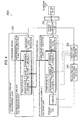
- Fig. 1 is a diagram of an overall schematic configuration of a mobile communication system 1 according to this embodiment. As illustrated in Fig. 1 , the mobile communication system 1 includes a base station 100 and mobile stations 200A, 200B.
- the base station 100 transmits radio signals to the mobile stations 200A, 200B, more specifically to the inside of a cell C1. In addition, the base station 100 receives radio signals from the mobile stations 200A, 200B. In this embodiment, the base station 100 configures a transmitter and the mobile stations 200A, 200B each configure a receiver.
- the mobile station 200A is located within the cell C1 but is located at a cell edge of the cell C1 where a path loss of a radio signal from the base station 100 is large.
- the mobile station 200B is located in the center within the cell C1. For this reason, the path loss of a radio signal from the base station 100 in the mobile station 200B is smaller than the path loss in the mobile station 200A.
- the base station 100 transmits radio signals to the mobile stations 200A, 200B located in the cell C1, the radio signals including multiple orthogonal signals that are orthogonal to each other, and multiple non-orthogonal signals that are not orthogonal to each other.
- the mobile communication system 1 uses a combination of orthogonal multiple access for implementing concurrent communications with multiple mobile stations using orthogonal signals, and non-orthogonal multiple access for implementing concurrent communications with the multiple mobile stations using non-orthogonal signals (hereinafter referred to as hybrid orthogonal/non-orthogonal multiple access).
- Parts (a) to (c) of Fig. 2 illustrate radio resource allocation images in the orthogonal multiple access, the non-orthogonal multiple access, and the hybrid orthogonal/non-orthogonal multiple access.
- radio resources allocated to mobile stations (users) do not overlap each other in the bandwidth in a frequency domain/time domain/space domain. For this reason, in principle, the orthogonal multiple access does not need to remove interferences from the radio resources allocated to the other mobile stations.
- the orthogonal multiple access is also used in Long Term Evolution (LTE) standardized by the 3GPP.
- LTE Long Term Evolution
- radio resources allocated to mobile stations (users) partly overlap each other in the bandwidth mentioned above. For this reason, each mobile station only has to remove multiple access interferences of a prescribed number or less according to the number of multiplexed radio resources.
- This embodiment reduces a signal processing load associated with removal of multiple access interferences by introducing the aforementioned hybrid orthogonal/non-orthogonal multiple access, and specifies a radio interface enabling a mobile station to recognize the number of multiple access interferences to be removed.
- Fig. 3 is a diagram of a functional block configuration of a transmission unit of the base station 100.
- Fig. 4 is a diagram of a functional block configuration of a reception unit of the mobile station 200A.
- a transmission unit of the base station 100 includes coding/data modulating units 110, a base station scheduler 120, a hybrid orthogonal/non-orthogonal multiplexer 130, a control signal generator 140, a control signal resource allocator 150 and a physical channel multiplexer 160.
- the coding/data modulating units 110 perform division of transmission data, channel coding/data modulation, transmission power setting, and resource block allocation for their respective predetermined users (user k).
- the coding/data modulating units 110 allocate radio resource blocks to orthogonal signals and non-orthogonal signals included in radio signals to be transmitted to the mobile stations 200A, 200B.
- the base station scheduler 120 controls the coding/data modulating units 110, the hybrid orthogonal/non-orthogonal multiplexer 130 and the control signal generator 140 on the basis of information such as feedbacks of Circuit State Information (CSI) from the mobile stations 200A, 200B, and the path loss between the base station 100 and each of the mobile stations 200A, 200B.
- CSI Circuit State Information
- the base station scheduler 120 schedules signals multiplexed as non-orthogonal signals for multiple mobile stations (for example, the mobile stations 200A, 200B), on the basis of the path losses of the signals multiplexed as non-orthogonal signals to the respective multiple mobile stations, in such a way that the signals can have a large difference in the path loss among them.
- Fig. 5 illustrates an example of scheduling of non-orthogonal signals for mobile stations in the base station 100.
- the example illustrated in Fig. 5 uses non-orthogonal signals with which at maximum four users (mobile stations) are multiplexed.
- multiple signals are not orthogonal to each other, in other words, the same radio resource block in the frequency domain or time domain is allocated to the multiple signals.
- signals are multiplexed as non-orthogonal signals sequentially from a signal addressed to a mobile station having the smallest path loss to a signal addressed to a mobile station having the largest path loss.
- a signal addressed to a mobile station having a small path loss only needs low transmission power to surely obtain a desired SNR, and therefore accounts for a small share in a vertical axis (transmission power) direction in Fig. 5 .
- a signal addressed to a mobile station having a large path loss needs high transmission power to surely obtain a desired SNR, and therefore accounts for a large share in the vertical axis (transmission power) direction in Fig. 5 .
- the user (mobile station) having, for example, the second smallest path loss needs to remove interferences from the signals allocated to the two mobile stations having the larger path losses than the user (see explanation in the drawing).
- the example illustrated in Fig. 5 also uses orthogonal signals to which different radio resource blocks in the frequency domain and time domain are allocated, i.e., multiple signals orthogonal to each other. Since the aforementioned interference does not occur between the orthogonal signals, the mobile stations do not have to remove the interference.
- the hybrid orthogonal/non-orthogonal multiplexer 130 multiplexes the orthogonal signals and the non-orthogonal signals. Specifically, the hybrid orthogonal/non-orthogonal multiplexer 130 multiplexes signals (radio resource blocks) outputted from the multiple coding/data modulating units 110 under the control of the base station scheduler 120. As a result, the multiplexed signals as illustrated in Fig. 5 are generated.
- the control signal generator 140 generates various kinds of control signals to be broadcasted to the mobile stations 200A, 200B.
- the maximum number of signals multiplexed as non-orthogonal signals (for example, quad multiplexing) is known to the base station 100 and the mobile stations 200A, 200B.
- the control signal generator 140 generates a control signal necessary for a mobile station to demodulate and cancel radio signals addressed to other mobile stations (other devices).
- the control signal generator 140 can generate a signal including the following control information or reference signal in order for the mobile station to demodulate and cancel radio signals addressed to other mobile stations (other devices):
- the control signal generator 140 may generate a control signal including any one or any combination of the above (a) to (d).
- the control signal generator 140 transmits the generated control signal to the mobile stations 200A, 200B via the control signal resource allocator 150 and the physical channel multiplexer 160.
- the control signal resource allocator 150 allocates a radio resource block to the control signal outputted from the control signal generator 140.
- the physical channel multiplexer 160 multiplexes baseband signals outputted from the hybrid orthogonal/non-orthogonal multiplexer 130 and the control signal outputted from the control signal resource allocator 150 with each other in physical channels.
- the signals outputted from the physical channel multiplexer 160 are subjected to IFFT and Cyclic Prefix (CP) is added to the resultant signals. Then, the signals are transmitted to the mobile stations 200A, 200B from a transmission antenna.
- the hybrid orthogonal/non-orthogonal multiplexer 130 and the physical channel multiplexer 160 configure a radio signal transmission unit to transmit orthogonal signals and non-orthogonal signals to multiple mobile stations (receivers) located within the cell C1.
- the mobile station 200A includes a physical channel segmentation unit 210, data demodulating/decoding units 220, a target user control signal detector 230 and an interfering user control signal detector 240.
- the mobile station 200B has the same functional block configuration as the mobile station 200A.
- the physical channel segmentation unit 210 receives radio signals transmitted from the base station 100, and performs segmentation of physical channels included in the radio signals. As described above, the radio signals received by the physical channel segmentation unit 210 include the orthogonal signals and the non-orthogonal signals. The segmented physical channels are outputted to the data demodulating/decoding units 220, the target user control signal detector 230 and the interfering user control signal detector 240. In this embodiment, the physical channel segmentation unit 210 configures a radio signal reception unit.
- multiple data demodulating/decoding units 220 There are provided multiple data demodulating/decoding units 220. Specifically, the data demodulating/decoding units 220 are provided for interfering users and a target user according to the number of signals (users) multiplexed as non-orthogonal signals. In this embodiment, since at maximum four users are multiplexed, it is preferable to also provide four data demodulating/decoding units 220.
- the data demodulating/decoding units 220 each execute radio resource block extraction, interference canceller, channel estimation, demodulation/decoding and decoded data combining.
- the interference canceller of the data demodulating/decoding units 220 extracts the non-orthogonal signal addressed to the mobile station 200A from the multiple non-orthogonal signals by demodulating and cancelling the radio signals addressed to the other mobile stations (receivers) by use of the orthogonal signals (for example, the foregoing control information and reference signal) included in the received radio signals.
- the interference canceller extracts the signal addressed to the device itself from the received non-orthogonal signals by signal separation through predetermined signal processing, and cancels the interferences from the signals addressed to the other receivers. Since the maximum number of multiplexed non-orthogonal signals is known (quad multiplexing in this embodiment), the interference canceller demodulates and cancels the radio signals addressed to the other receivers within the range not exceeding the known maximum number of non-orthogonal signals. Note that the interference cancelling method will be described later.
- the data demodulating/decoding unit 220 demodulates the signal included in the orthogonal signals and addressed to the mobile station 200A and the signal extracted by the interference canceller and addressed to the mobile station 200A.
- the target user control signal detector 230 detects the control signal addressed to the target user, i.e., the device (mobile station 200A) itself.
- the target user control signal detector 230 provides the detected control signal to the data demodulating/decoding unit 220 (for the target user). Any one or combination of the above (a) to (d) is used as the control signal.
- the interfering user control signal detector 240 detects the control signals addressed to the interfering users, i.e., the other devices (for example, the mobile station 200B). As similar to the target user control signal detector 230, the interfering user control signal detector 240 provides the detected control signals to the data demodulating/decoding units 220 (for the interfering users).
- the signal processing in the interference canceller in the data demodulating/decoding units 220 is explained briefly.
- the interference canceller cannot remove the signal of the mobile station 200B located in the center within the cell C1.
- the data demodulating/decoding units 220 perform the demodulation/decoding directly.
- the signal processing in the user 1 can be explained based on the following computational expression:
- the user 1 denotes the mobile station 200A located at the cell edge of the cell C1
- the user 2 denotes the mobile station 200B located in the center in the cell C1.
- P 1 and P 2 are transmission powers of the user 1 and the user 2
- h 1 and h 2 are channel gains of the user 1 and the user 2.
- the received signals (R 1 ) include an interference from the mobile station (user 2) located in the cell center, but the user 1 cannot remove the interference from the user 2 because having a poorer SNR than the user 2.
- the user 1 executes the demodulation/decoding directly without removing the signal of the user 2.
- the received signals (R 2 ) include an interference from the mobile station (user 1) located at the cell edge. Since the user 2 has a better SNR than the user 1, the user 2 removes the signal of the user 1 by decoding it once, and then demodulates/decodes the signal of the user 2 after removing the signal of the user 1.
- radio resource block allocation examples 1 to 4 are described with reference to Figs. 6 to 9 .
- Fig. 6 is an explanatory diagram of a radio resource block allocation example 1.
- a radio resource domain (level) for non-orthogonal multiplexing is newly defined (hereinafter, referred to as a non-orthogonal multiplex domain).
- a radio resource blocks allocated to non-orthogonal signals is defined in the frequency domain, the time domain and the non-orthogonal multiplex domain.
- the non-orthogonal multiplex domain has multiple levels according to the number of interference cancellations (or the order of interference cancellations) by the data demodulating/decoding units 220 (the interference canceller). Specifically, the number of interference cancellations is determined from the path losses between the base station 100 and the mobile stations 200A, 200B, and the radio resource block at a higher level is allocated for a smaller path loss. In other words, the coding/data modulating units 110 (allocation unit) of the base station 100 allocate, to non-orthogonal signals, a radio resource block defined in the frequency domain, the time domain and the non-orthogonal multiplex domain having the multiple levels according to the number of interference cancellations (the path losses to the mobile stations 200A, 200B or etc.).
- the mobile station 200A, 200B (user itself) removes signals of mobile stations (interference removal target users) assigned to lower levels than the mobile station itself in the non-orthogonal multiplex domain within the radio resource block in the frequency/time domain to which the mobile station itself is assigned (each arrow in the drawing indicates the radio resource block allocated to non-orthogonal signals at the lower levels to be removed by a mobile station at the highest level).
- the interference canceller of the mobile station 200A, 200B cancels the non-orthogonal signals whose allocated radio resource block is at lower levels than that of the mobile station itself.
- a mobile station (user) and a radio resource block targeted for interference removal are automatically and uniquely determined based on the radio resource block allocated thereto.
- Fig. 7 is an explanatory diagram of a radio resource block allocation example 2.
- hierarchical radio resource blocks are defined. Specifically, the size (in the frequency/time domain) of a radio resource block at a lower level is defined as being larger than the size (in the frequency/time domain) of a radio resource block at a higher level.
- the coding/data modulating units 110 (allocation unit) of the base station 100 allocate radio resource blocks to non-orthogonal signals in such a manner that a radio resource block at a lower level in the non-orthogonal multiplex domain has a larger size in the frequency domain or time domain than a radio resource block at a higher level in the non-orthogonal multiplex domain has.
- part of the signal processing required to remove interferences can be also used for removal of other interferences, and thereby the processing volume is reduced (the number of interference removal target users is reduced by one as compared with the allocation example 1).
- a user having a larger path loss is multiplexed at a lower level, and accordingly a radio resource block in a relatively large size is allocated to a user having a large path loss, i.e., a user located at a cell edge. This resource allocation is expected to produce an effect of securing the coverage of the base station 100.
- Parts (a) and (b) of Fig. 8 are explanatory diagrams of a radio resource block allocation example 3.
- a certain limitation is imposed on radio resource block allocation. Specifically, concurrent allocation of radio resource blocks in two or more frequency/time domains to a single user as illustrated in part (b) of Fig. 8 is allowed, but allocation of two or more levels to the single user as illustrated in part (a) of Fig. 8 is not allowed.
- the coding/data modulating units 110 (allocation unit) of the base station 100 allocate the radio resource blocks only at any of the levels in the non-orthogonal multiplex domain.
- radio resource blocks at a certain level in the non-orthogonal multiplex domain are allocated, which in turn suppresses variations in processing delay or the like associated with interference removal.
- Fig. 9 is an explanatory diagram of a radio resource block allocation example 4.
- transport block allocation methods coding methods
- coding methods are specified.
- candidate coding methods a method of coding in the radio resource blocks independently (Separate coding); a method of coding in the radio resource blocks collectively (Joint coding); or a hybrid method of the above two.
- the Separate coding is needed for the removal of interferences from non-orthogonal signals addressed to other mobile stations as described above.
- the Separate coding is applied to a low level in the non-orthogonal multiplex domain and the Joint coding is applied to a high level (the highest level in the example in Fig. 9 ) .
- radio resource blocks at the low level in the non-orthogonal multiplex domain is coded in the unit of each radio resource block
- information allocated to radio resource blocks at the high level in the non-orthogonal multiplex domain is coded in the unit of two or more radio resource blocks.
- the Joint coding is applied to the three consecutive radio resource blocks in the frequency/time domain in the example illustrated in Fig. 9
- radio resource blocks to which the Joint coding is applied do not necessarily have to be consecutive.
- the Joint coding is applied limitedly to the high level since signals multiplexed at the high level have a low possibility of being targeted for removal of interferences from non-orthogonal signals. This limited application can lead to an improvement in coding gain or efficient utilization of radio resources.
- Fig. 10 is an explanatory diagram of a radio resource block allocation example 5.
- the allocation example 5 is similar to the allocation example 1 illustrated in Fig. 6 , but is different in that boundaries in a radio resource block (frequency/time domain) are offset among the levels in the non-orthogonal multiplex domain.
- the coding/data modulating units 110 (allocation unit) of the base station 100 allocate radio resource block to non-orthogonal signals such that the boundaries in the frequency domain or time domain of the radio resource block at a low level in the non-orthogonal multiplex domain is offset from the boundaries in the frequency domain or time domain of the radio resource block at a high level in the non-orthogonal multiplex domain.
- the boundaries at all the levels are offset in the same direction (right direction in the drawing) in the example illustrated in Fig. 10 , the boundaries may be offset in different directions among the levels.
- the boundaries of the radio resource blocks are offset and do not coincide with each other among the levels, and therefore reduction in interference among the levels and reduction in peak transmission power can be achieved.
- a mobile station (user) and a radio resource block targeted for interference removal are automatically and uniquely determined based on the radio resource block allocated thereto.
- the processing load for removing multiple access interferences due to use of non-orthogonal signals can be reduced, and therefore the cost increase and processing delay of mobile stations and the like can be suppressed in a situation where hybrid orthogonal/non-orthogonal multiple access is introduced.
- Fig. 11 illustrates a radio resource block allocation example according to a modified example of the present invention.
- the coding/data modulating units 110 (allocation unit) of the base station 100 apply filtering to the vicinities of the boundaries of a radio resource block (in the frequency/time domain). By the filtering, the transmission power density of a radio resource block is lowered toward the boundary.
- filtering in which the transmission power of a radio resource block allocated to a user at the level 1 in the non-orthogonal multiplex domain (located at the cell edge) is lowered smoothly toward the boundaries of the radio resource block.
- Such filtering can reduce out-of-band transmission and peak power.
- an interference with a user at the level 2 (located at the cell center) can be reduced as illustrated in Fig. 11 .
- the coding/data modulating units 110 may vary the intensity of the filtering according to the levels in the non-orthogonal multiplex domain. For instance, a roll-off rate of the filtering may be increased as the level becomes lower. Note that such filtering can be applied to not only downlink and but also uplink.
- the examples of downlink from the base station 100 to the mobile stations 200A, 200B are described.
- the hybrid orthogonal/non-orthogonal multiple access according to the present invention can be applied to uplink.
- the present invention can be also applied to radio communications not only between the base station and mobile stations, but also between base stations.
- a receiver capable of using non-orthogonal multiple access while suppressing cost increase and processing delay.
Landscapes
- Engineering & Computer Science (AREA)
- Signal Processing (AREA)
- Computer Networks & Wireless Communication (AREA)
- Quality & Reliability (AREA)
- Power Engineering (AREA)
- Mobile Radio Communication Systems (AREA)
- Radio Transmission System (AREA)
Applications Claiming Priority (3)
| Application Number | Priority Date | Filing Date | Title |
|---|---|---|---|
| JP2011114026 | 2011-05-20 | ||
| JP2011227143A JP5785845B2 (ja) | 2011-05-20 | 2011-10-14 | 受信装置、送信装置及び無線通信方法 |
| PCT/JP2012/062646 WO2012161080A1 (fr) | 2011-05-20 | 2012-05-17 | Dispositif de réception, dispositif d'émission et procédé de communication sans fil |
Publications (2)
| Publication Number | Publication Date |
|---|---|
| EP2712105A1 true EP2712105A1 (fr) | 2014-03-26 |
| EP2712105A4 EP2712105A4 (fr) | 2015-02-25 |
Family
ID=47217158
Family Applications (1)
| Application Number | Title | Priority Date | Filing Date |
|---|---|---|---|
| EP12789044.0A Withdrawn EP2712105A4 (fr) | 2011-05-20 | 2012-05-17 | Dispositif de réception, dispositif d'émission et procédé de communication sans fil |
Country Status (4)
| Country | Link |
|---|---|
| US (2) | US9713161B2 (fr) |
| EP (1) | EP2712105A4 (fr) |
| JP (1) | JP5785845B2 (fr) |
| WO (1) | WO2012161080A1 (fr) |
Cited By (2)
| Publication number | Priority date | Publication date | Assignee | Title |
|---|---|---|---|---|
| WO2015167714A1 (fr) * | 2014-04-28 | 2015-11-05 | Intel IP Corporation | Systèmes sans fil et procédés d'accès multiple non orthogonal (noma) |
| EP3098997A4 (fr) * | 2014-01-22 | 2017-08-23 | China Academy Of Telecommunications Technology | Procédé de détection de transmission et de réception de données, station de base, et équipement d'utilisateur |
Families Citing this family (30)
| Publication number | Priority date | Publication date | Assignee | Title |
|---|---|---|---|---|
| JP5864200B2 (ja) | 2011-05-20 | 2016-02-17 | 株式会社Nttドコモ | 受信装置、送信装置及び無線通信方法 |
| JP5900884B2 (ja) * | 2012-02-17 | 2016-04-06 | シャープ株式会社 | 制御局装置、および無線通信システム |
| JP5830478B2 (ja) | 2013-02-06 | 2015-12-09 | 株式会社Nttドコモ | 無線基地局、ユーザ端末及び無線通信方法 |
| JP5894105B2 (ja) | 2013-04-04 | 2016-03-23 | 株式会社Nttドコモ | 無線基地局、ユーザ端末及び無線通信方法 |
| JP6364159B2 (ja) * | 2013-06-28 | 2018-07-25 | 株式会社Nttドコモ | 無線基地局、ユーザ端末、無線通信方法、及び無線通信システム |
| EP3017556B1 (fr) * | 2013-08-07 | 2024-03-20 | Huawei Technologies Co., Ltd. | Système et procédé de communications numériques évolutives avec paramètres de système adaptatif |
| JP2015050575A (ja) * | 2013-08-30 | 2015-03-16 | 株式会社Nttドコモ | 無線基地局、ユーザ端末及び送信電力制御方法 |
| CN104868983B (zh) * | 2014-02-26 | 2018-03-27 | 电信科学技术研究院 | 一种数据传输、数据接收检测方法及基站、用户设备 |
| US9712272B2 (en) * | 2014-06-02 | 2017-07-18 | Intel IP Corporation | User equipment and method for dynamic non-orthogonal multiple access communication |
| US10051634B2 (en) | 2014-06-10 | 2018-08-14 | Qualcomm Incorporated | Devices and methods for facilitating non-orthogonal wireless communications |
| CN105471543B (zh) * | 2014-08-01 | 2020-08-14 | 株式会社Ntt都科摩 | 发送装置和发送方法 |
| JP6462289B2 (ja) * | 2014-09-26 | 2019-01-30 | 日本放送協会 | 送信装置及び受信装置 |
| US10555314B2 (en) | 2014-10-07 | 2020-02-04 | Hfi Innovation Inc. | Signaling of network-assisted intra-cell interference cancellation and suppression |
| KR20160048360A (ko) * | 2014-10-24 | 2016-05-04 | 삼성전자주식회사 | 이동 통신 시스템에서 간섭 측정에 기반한 신호 수신 방법 및 장치 |
| EP3216295B1 (fr) * | 2014-11-04 | 2019-07-17 | Telefonaktiebolaget LM Ericsson (publ) | Allocation de ressources se chevauchant partiellement à des dispositifs de communication |
| JP6380071B2 (ja) | 2014-12-11 | 2018-08-29 | ソニー株式会社 | 通信制御装置、無線通信装置、通信制御方法及び無線通信方法 |
| WO2016101108A1 (fr) * | 2014-12-22 | 2016-06-30 | 华为技术有限公司 | Procédé et dispositif de transmission d'informations d'indication |
| EP3226636B1 (fr) | 2014-12-22 | 2020-07-29 | Huawei Technologies Co., Ltd. | Procédé et dispositif de transmission d'informations d'indication |
| EP3229541B1 (fr) * | 2014-12-31 | 2019-04-03 | Huawei Technologies Co. Ltd. | Procédé et appareil de communication |
| EP3258626A4 (fr) | 2015-01-14 | 2018-10-31 | Sharp Kabushiki Kaisha | Dispositif de station de base et dispositif de terminal |
| US10389477B2 (en) * | 2015-03-15 | 2019-08-20 | Qualcomm Incorporated | Devices and methods for facilitating a non-orthogonal underlay in wireless communications systems |
| US10448405B2 (en) * | 2015-03-19 | 2019-10-15 | Qualcomm Incorporated | Methods and apparatus for mitigating resource conflicts between ultra low latency (ULL) and legacy transmissions |
| JP6606735B2 (ja) | 2015-03-26 | 2019-11-20 | インテル アイピー コーポレーション | 装置、プログラム、及び非一時的コンピュータ読み取り可能記憶媒体 |
| KR102607173B1 (ko) | 2015-04-02 | 2023-11-28 | 삼성전자주식회사 | 무선 통신 시스템에서 다운링크 정보를 송신하는 방법 및 장치 |
| EP3297190B1 (fr) | 2015-05-14 | 2020-03-25 | Sharp Kabushiki Kaisha | Dispositif de station de base et dispositif de terminal |
| US11212147B2 (en) | 2015-10-23 | 2021-12-28 | Huawei Technologies Co., Ltd. | Systems and methods for configuring carriers using overlapping sets of candidate numerologies |
| JP6243386B2 (ja) * | 2015-10-26 | 2017-12-06 | 株式会社Nttドコモ | ユーザ端末 |
| WO2017090708A1 (fr) * | 2015-11-27 | 2017-06-01 | 株式会社Nttドコモ | Terminal d'utilisateur, station de base sans fil et procédé de communication sans fil |
| JP6555410B2 (ja) | 2016-03-09 | 2019-08-07 | 富士通株式会社 | 基地局、移動局、通信システムおよび通信方法 |
| US10666374B2 (en) | 2018-05-11 | 2020-05-26 | At&T Intellectual Property I, L.P. | Non-orthogonal multiple access for uplink data transmission for 5G or other next generation network |
Family Cites Families (12)
| Publication number | Priority date | Publication date | Assignee | Title |
|---|---|---|---|---|
| US6700881B1 (en) * | 1998-03-02 | 2004-03-02 | Samsung Electronics Co., Ltd. | Rate control device and method for CDMA communication system |
| US7292552B2 (en) * | 2002-03-14 | 2007-11-06 | Qualcomm Incorporated | Method and apparatus for reducing interference in a wireless communication system |
| US7535980B2 (en) * | 2005-03-01 | 2009-05-19 | Broadcom Corporation | Selectively disabling interference cancellation based on channel dispersion estimation |
| JP2009010752A (ja) * | 2007-06-28 | 2009-01-15 | Ntt Docomo Inc | 移動通信システム、基地局装置及び方法 |
| US9544911B2 (en) * | 2007-08-10 | 2017-01-10 | Futurewei Technologies, Inc. | System and method for assigning communications resources in a wireless communications system |
| JP5366494B2 (ja) | 2007-10-10 | 2013-12-11 | パナソニック株式会社 | マルチキャリア送信装置 |
| EP2237460A4 (fr) * | 2007-12-25 | 2014-05-28 | Panasonic Corp | Dispositif de radiocommunication, système de radiocommunication et procédé de radiocommunication |
| US8358678B2 (en) * | 2008-05-06 | 2013-01-22 | Telefonaktiebolaget Lm Ericsson (Publ) | Frequency hopping offsetting for multiple users reusing one slot (MUROS) |
| EP2139186B1 (fr) * | 2008-06-27 | 2014-07-16 | Alcatel Lucent | Détérmination de l'ordre de décodage des signaux pour une suppression d'interférences successive |
| US8243690B2 (en) * | 2008-07-09 | 2012-08-14 | Intel Corporation | Bandwidth allocation base station and method for allocating uplink bandwidth using SDMA |
| EP2534877A4 (fr) * | 2010-02-11 | 2015-07-08 | Nokia Corp | Appareil et procédé pour l'allocation de ressources de communication dans un système de communication |
| JP2011227143A (ja) | 2010-04-15 | 2011-11-10 | Sanyo Electric Co Ltd | 表示装置 |
-
2011
- 2011-10-14 JP JP2011227143A patent/JP5785845B2/ja not_active Expired - Fee Related
-
2012
- 2012-05-17 EP EP12789044.0A patent/EP2712105A4/fr not_active Withdrawn
- 2012-05-17 WO PCT/JP2012/062646 patent/WO2012161080A1/fr active Application Filing
- 2012-05-17 US US14/111,224 patent/US9713161B2/en active Active
-
2017
- 2017-03-03 US US15/449,578 patent/US20170181175A1/en not_active Abandoned
Cited By (4)
| Publication number | Priority date | Publication date | Assignee | Title |
|---|---|---|---|---|
| EP3098997A4 (fr) * | 2014-01-22 | 2017-08-23 | China Academy Of Telecommunications Technology | Procédé de détection de transmission et de réception de données, station de base, et équipement d'utilisateur |
| US10014995B2 (en) | 2014-01-22 | 2018-07-03 | China Academy Of Telecommunications Technology | Data transmission method, data reception and detection method, base station and user equipment |
| WO2015167714A1 (fr) * | 2014-04-28 | 2015-11-05 | Intel IP Corporation | Systèmes sans fil et procédés d'accès multiple non orthogonal (noma) |
| US10003486B2 (en) | 2014-04-28 | 2018-06-19 | Intel IP Corporation | Non-orthogonal multiple access (NOMA) wireless systems and methods |
Also Published As
| Publication number | Publication date |
|---|---|
| US20170181175A1 (en) | 2017-06-22 |
| US9713161B2 (en) | 2017-07-18 |
| EP2712105A4 (fr) | 2015-02-25 |
| JP2013009289A (ja) | 2013-01-10 |
| JP5785845B2 (ja) | 2015-09-30 |
| WO2012161080A1 (fr) | 2012-11-29 |
| US20140029562A1 (en) | 2014-01-30 |
Similar Documents
| Publication | Publication Date | Title |
|---|---|---|
| US9713161B2 (en) | Method and apparatus for reducing interface within radio networks using non-orthogonal signal processing | |
| US11212047B2 (en) | Receiver, transmitter and radio communication method | |
| US9941912B2 (en) | Receiver, transmitter and radio communication method | |
| US9843406B2 (en) | Receiver, transmitter and radio communication method | |
| EP2557833A1 (fr) | Dispositif de station relais radio, dispositif de station de base radio et procédé d'allocation de fréquences de relais | |
| KR101336686B1 (ko) | 상이한 tdd 시스템들 사이에서 자원들을 스케줄링하는 방법 및 장치 | |
| US9226313B2 (en) | Transmission device, receiving device, transmission method and receiving method | |
| JP6088596B2 (ja) | 受信装置、送信装置及び無線通信方法 | |
| CN107113812B (zh) | 一种信息的传输方法、信息的处理方法和基站及用户设备 | |
| WO2023087315A1 (fr) | Procédés, dispositifs et support lisible par ordinateur pour des communications | |
| US8995308B2 (en) | Control channel architecture with control information distributed over multiple subframes | |
| JP6207637B2 (ja) | 受信装置、送信装置及び無線通信方法 | |
| JP6207582B2 (ja) | 受信装置、送信装置及び無線通信方法 | |
| JP6207581B2 (ja) | 受信装置、送信装置及び無線通信方法 | |
| EP2608594A1 (fr) | Procédé de transmission par relais, noeud relais et station de base sans fil |
Legal Events
| Date | Code | Title | Description |
|---|---|---|---|
| PUAI | Public reference made under article 153(3) epc to a published international application that has entered the european phase |
Free format text: ORIGINAL CODE: 0009012 |
|
| 17P | Request for examination filed |
Effective date: 20131017 |
|
| AK | Designated contracting states |
Kind code of ref document: A1 Designated state(s): AL AT BE BG CH CY CZ DE DK EE ES FI FR GB GR HR HU IE IS IT LI LT LU LV MC MK MT NL NO PL PT RO RS SE SI SK SM TR |
|
| DAX | Request for extension of the european patent (deleted) | ||
| A4 | Supplementary search report drawn up and despatched |
Effective date: 20150127 |
|
| RIC1 | Information provided on ipc code assigned before grant |
Ipc: H04B 1/10 20060101ALI20150121BHEP Ipc: H04J 11/00 20060101ALI20150121BHEP Ipc: H04J 99/00 20090101AFI20150121BHEP Ipc: H04W 72/08 20090101ALI20150121BHEP Ipc: H04W 72/04 20090101ALI20150121BHEP |
|
| 17Q | First examination report despatched |
Effective date: 20190311 |
|
| STAA | Information on the status of an ep patent application or granted ep patent |
Free format text: STATUS: THE APPLICATION IS DEEMED TO BE WITHDRAWN |
|
| 18D | Application deemed to be withdrawn |
Effective date: 20190723 |