EP2711200A1 - Fahrzeugluftreifen - Google Patents
Fahrzeugluftreifen Download PDFInfo
- Publication number
- EP2711200A1 EP2711200A1 EP13180011.2A EP13180011A EP2711200A1 EP 2711200 A1 EP2711200 A1 EP 2711200A1 EP 13180011 A EP13180011 A EP 13180011A EP 2711200 A1 EP2711200 A1 EP 2711200A1
- Authority
- EP
- European Patent Office
- Prior art keywords
- groove
- profile
- vehicle tire
- base
- pneumatic vehicle
- Prior art date
- Legal status (The legal status is an assumption and is not a legal conclusion. Google has not performed a legal analysis and makes no representation as to the accuracy of the status listed.)
- Granted
Links
Images
Classifications
-
- B—PERFORMING OPERATIONS; TRANSPORTING
- B60—VEHICLES IN GENERAL
- B60C—VEHICLE TYRES; TYRE INFLATION; TYRE CHANGING; CONNECTING VALVES TO INFLATABLE ELASTIC BODIES IN GENERAL; DEVICES OR ARRANGEMENTS RELATED TO TYRES
- B60C11/00—Tyre tread bands; Tread patterns; Anti-skid inserts
- B60C11/03—Tread patterns
- B60C11/0306—Patterns comprising block rows or discontinuous ribs
- B60C11/0309—Patterns comprising block rows or discontinuous ribs further characterised by the groove cross-section
-
- B—PERFORMING OPERATIONS; TRANSPORTING
- B60—VEHICLES IN GENERAL
- B60C—VEHICLE TYRES; TYRE INFLATION; TYRE CHANGING; CONNECTING VALVES TO INFLATABLE ELASTIC BODIES IN GENERAL; DEVICES OR ARRANGEMENTS RELATED TO TYRES
- B60C11/00—Tyre tread bands; Tread patterns; Anti-skid inserts
- B60C11/03—Tread patterns
- B60C11/13—Tread patterns characterised by the groove cross-section, e.g. for buttressing or preventing stone-trapping
- B60C11/1307—Tread patterns characterised by the groove cross-section, e.g. for buttressing or preventing stone-trapping with special features of the groove walls
-
- B—PERFORMING OPERATIONS; TRANSPORTING
- B60—VEHICLES IN GENERAL
- B60C—VEHICLE TYRES; TYRE INFLATION; TYRE CHANGING; CONNECTING VALVES TO INFLATABLE ELASTIC BODIES IN GENERAL; DEVICES OR ARRANGEMENTS RELATED TO TYRES
- B60C11/00—Tyre tread bands; Tread patterns; Anti-skid inserts
- B60C11/03—Tread patterns
- B60C2011/0337—Tread patterns characterised by particular design features of the pattern
- B60C2011/0339—Grooves
- B60C2011/0341—Circumferential grooves
- B60C2011/0353—Circumferential grooves characterised by width
-
- B—PERFORMING OPERATIONS; TRANSPORTING
- B60—VEHICLES IN GENERAL
- B60C—VEHICLE TYRES; TYRE INFLATION; TYRE CHANGING; CONNECTING VALVES TO INFLATABLE ELASTIC BODIES IN GENERAL; DEVICES OR ARRANGEMENTS RELATED TO TYRES
- B60C11/00—Tyre tread bands; Tread patterns; Anti-skid inserts
- B60C11/03—Tread patterns
- B60C2011/0337—Tread patterns characterised by particular design features of the pattern
- B60C2011/0339—Grooves
- B60C2011/0341—Circumferential grooves
- B60C2011/0355—Circumferential grooves characterised by depth
-
- B—PERFORMING OPERATIONS; TRANSPORTING
- B60—VEHICLES IN GENERAL
- B60C—VEHICLE TYRES; TYRE INFLATION; TYRE CHANGING; CONNECTING VALVES TO INFLATABLE ELASTIC BODIES IN GENERAL; DEVICES OR ARRANGEMENTS RELATED TO TYRES
- B60C11/00—Tyre tread bands; Tread patterns; Anti-skid inserts
- B60C11/03—Tread patterns
- B60C2011/0337—Tread patterns characterised by particular design features of the pattern
- B60C2011/0339—Grooves
- B60C2011/0358—Lateral grooves, i.e. having an angle of 45 to 90 degees to the equatorial plane
-
- B—PERFORMING OPERATIONS; TRANSPORTING
- B60—VEHICLES IN GENERAL
- B60C—VEHICLE TYRES; TYRE INFLATION; TYRE CHANGING; CONNECTING VALVES TO INFLATABLE ELASTIC BODIES IN GENERAL; DEVICES OR ARRANGEMENTS RELATED TO TYRES
- B60C11/00—Tyre tread bands; Tread patterns; Anti-skid inserts
- B60C11/03—Tread patterns
- B60C2011/0337—Tread patterns characterised by particular design features of the pattern
- B60C2011/0339—Grooves
- B60C2011/0358—Lateral grooves, i.e. having an angle of 45 to 90 degees to the equatorial plane
- B60C2011/036—Narrow grooves, i.e. having a width of less than 3 mm
-
- B—PERFORMING OPERATIONS; TRANSPORTING
- B60—VEHICLES IN GENERAL
- B60C—VEHICLE TYRES; TYRE INFLATION; TYRE CHANGING; CONNECTING VALVES TO INFLATABLE ELASTIC BODIES IN GENERAL; DEVICES OR ARRANGEMENTS RELATED TO TYRES
- B60C11/00—Tyre tread bands; Tread patterns; Anti-skid inserts
- B60C11/03—Tread patterns
- B60C2011/0337—Tread patterns characterised by particular design features of the pattern
- B60C2011/0339—Grooves
- B60C2011/0358—Lateral grooves, i.e. having an angle of 45 to 90 degees to the equatorial plane
- B60C2011/0365—Lateral grooves, i.e. having an angle of 45 to 90 degees to the equatorial plane characterised by width
-
- B—PERFORMING OPERATIONS; TRANSPORTING
- B60—VEHICLES IN GENERAL
- B60C—VEHICLE TYRES; TYRE INFLATION; TYRE CHANGING; CONNECTING VALVES TO INFLATABLE ELASTIC BODIES IN GENERAL; DEVICES OR ARRANGEMENTS RELATED TO TYRES
- B60C11/00—Tyre tread bands; Tread patterns; Anti-skid inserts
- B60C11/03—Tread patterns
- B60C2011/0337—Tread patterns characterised by particular design features of the pattern
- B60C2011/0339—Grooves
- B60C2011/0358—Lateral grooves, i.e. having an angle of 45 to 90 degees to the equatorial plane
- B60C2011/0367—Lateral grooves, i.e. having an angle of 45 to 90 degees to the equatorial plane characterised by depth
-
- B—PERFORMING OPERATIONS; TRANSPORTING
- B60—VEHICLES IN GENERAL
- B60C—VEHICLE TYRES; TYRE INFLATION; TYRE CHANGING; CONNECTING VALVES TO INFLATABLE ELASTIC BODIES IN GENERAL; DEVICES OR ARRANGEMENTS RELATED TO TYRES
- B60C11/00—Tyre tread bands; Tread patterns; Anti-skid inserts
- B60C11/03—Tread patterns
- B60C2011/0337—Tread patterns characterised by particular design features of the pattern
- B60C2011/0339—Grooves
- B60C2011/0358—Lateral grooves, i.e. having an angle of 45 to 90 degees to the equatorial plane
- B60C2011/0367—Lateral grooves, i.e. having an angle of 45 to 90 degees to the equatorial plane characterised by depth
- B60C2011/0369—Lateral grooves, i.e. having an angle of 45 to 90 degees to the equatorial plane characterised by depth with varying depth of the groove
-
- B—PERFORMING OPERATIONS; TRANSPORTING
- B60—VEHICLES IN GENERAL
- B60C—VEHICLE TYRES; TYRE INFLATION; TYRE CHANGING; CONNECTING VALVES TO INFLATABLE ELASTIC BODIES IN GENERAL; DEVICES OR ARRANGEMENTS RELATED TO TYRES
- B60C11/00—Tyre tread bands; Tread patterns; Anti-skid inserts
- B60C11/03—Tread patterns
- B60C2011/0337—Tread patterns characterised by particular design features of the pattern
- B60C2011/0339—Grooves
- B60C2011/0358—Lateral grooves, i.e. having an angle of 45 to 90 degees to the equatorial plane
- B60C2011/0372—Lateral grooves, i.e. having an angle of 45 to 90 degees to the equatorial plane with particular inclination angles
-
- B—PERFORMING OPERATIONS; TRANSPORTING
- B60—VEHICLES IN GENERAL
- B60C—VEHICLE TYRES; TYRE INFLATION; TYRE CHANGING; CONNECTING VALVES TO INFLATABLE ELASTIC BODIES IN GENERAL; DEVICES OR ARRANGEMENTS RELATED TO TYRES
- B60C11/00—Tyre tread bands; Tread patterns; Anti-skid inserts
- B60C11/03—Tread patterns
- B60C2011/0337—Tread patterns characterised by particular design features of the pattern
- B60C2011/0339—Grooves
- B60C2011/0381—Blind or isolated grooves
Definitions
- the invention relates to a pneumatic vehicle tire having a tread profile, which is divided by circumferential grooves and circumferentially encircling profile positive, such as profile bands and / or profile block rows, wherein at least one profile positive is provided in which transverse grooves are arranged, which open into a profile positive limiting circumferential groove and the ends of which are located within the profile positive, wherein the transverse grooves are bounded on the surface of the profile of positive boundary edges whose mutual distance in the direction of the circumferential groove is greater.
- the transverse grooves extending into the profile positives usually have a U-shaped cross-section and end bluntly within the profile positive.
- the end portions of the transverse grooves are usually limited by a kind of end wall, which extends in the radial direction, starting from the groove bottom to the surface of the profile positive and thus forms the blunt end of the transverse groove.
- Pneumatic vehicle tires which should have a good transmission of steering forces, driving and braking forces even at high speeds, need profile positive in the tread, which ensure a comparatively high circumferential and lateral stiffness.
- conventional tread configurations there is often a trade-off between optimization of dry handling, hence good power transmission, and optimization of wet handling, ie drainage properties and aquaplaning behavior of the tire. Measures to improve dry handling usually result in a deterioration of wet handling.
- wet handling it is advantageous if the transverse grooves have a large width in order to ensure a good drainage of the tread in the direction of the circumferential grooves. The wider the transverse grooves, the lower the positive portion of the profile elements, whereby the stiffness of the profile elements suffers.
- the invention is therefore based on the object to perform a tread of a pneumatic vehicle tire of the type mentioned in such a way that the above-mentioned conflict of objectives between dry handling and wet handling is solved as well as possible.
- the transverse grooves each having in its radially inner region between 0.8 mm and 1.5 mm wide straight base groove and extending in its radially outer region between the boundary edges and the base groove groove flanks, wherein the However, the base groove extends at least substantially at a constant depth over its extent, but the radial extent of the base groove continuously decreases from the inner end region of the lateral groove in the direction of the circumferential groove, and wherein the one base groove wall protrudes in the radial direction over the other base groove wall, so that between the Base groove walls and the respective groove flanks formed common edges at different radial levels.
- transverse grooves Due to this special design of the transverse grooves with a base groove and groove flanks to the surface of the profile positive, the negative portion of the tread is increased in the near-surface region of the profile positive, without the rigidity of the profile positive being reduced. With transverse grooves according to the invention, therefore, a comparatively large amount of water can be conducted to the circumferential groove, which is a main drainage source, in the region near the surface.
- the groove flanks which do not extend to the full groove depth, stabilize the boundary edges of the transverse grooves on the surface of the profile positive and prevent the formation of curling effects.
- the narrow base grooves contribute to the stabilization of the Profilpositives and also have a "joint function", when rolling the tire, they facilitate a flattening of the tire in the footprint.
- transverse grooves as possible turbulence-free flow according to the invention transverse grooves is advantageous, which is supported according to the invention in that the radial distance of the common edge formed between the one base groove wall and the subsequent groove edge to the surface of the profile positive on the circumferential groove 3 mm 5 mm, and further that the radial distance of the common edge formed between the base groove surface projecting beyond the base groove and the second groove flank toward the surface of the profile positive at the circumferential groove is 2 mm to 3 mm.
- the transverse grooves are arranged in a profile band in such a way that these differently executed groove flanks connect at a part of the transverse grooves to the incoming edges and at a part of the transverse grooves to the outgoing edges.
- the groove flanks have at the inner end of the base groove an approximately equal radial distance to the surface of the profile positive, which is smaller than the radial distances of said common edges on the circumferential groove and preferably at most 1 mm. Accordingly, the transverse groove has the relevant for a good drainage features, namely increasing the circumferential groove depth and increasing the circumferential groove width on.
- the groove flanks are at least substantially equally large angles inclined surfaces relative to the radial direction.
- the boundary edges of the transverse groove running on the surface of the profile positive extend in a pointed manner at the transverse groove end in accordance with a further preferred embodiment of the invention. This measure provides above all for a stabilization of the tread inside end portions of the transverse grooves in the forces occurring during operation of the tire.
- a further measure according to the invention which optimizes the dewatering effect of the transverse grooves according to the invention, is that the groove flanks extend in the extension direction of the base groove beyond their end in the profile positive to the point of intersection of the boundary edges which are present on the surface of the profile positive.
- inventive transverse grooves is optimized by a further measure for the two possible Abrollidesen the tire, namely the fact that the provided on the surface of the profile positive limiting edges have different sized acute angle to the center line of the base groove.
- the base groove there is an optimum range of extension of the base groove to ensure the "hinge effect" of the transverse grooves as mentioned above while providing good stiffness of the profile positive and good drainage action of the transverse grooves.
- the advantageous extension length of the base groove in this respect is between 50% and 80% of the total extension length of the transverse groove.
- transverse grooves according to the invention in a profile band of the tread bordered on both sides by circumferential grooves takes place in particular in such a way that the transverse grooves in the circumferential direction open alternately into the one and the other circumferential groove. This measure is advantageous for the stiffness of the profile band and good drainage properties.
- the transverse grooves are further arranged with respect to the axial direction so that they extend at an angle of up to 50 ° to this. This measure is favorable for minimizing the rolling noise.
- At least one profile strip is provided in the tread, in which all transverse grooves extend at substantially coincident angles to the axial direction.
- the FIGS. 1 . 2 and 8th The profiled strip 1 has a width of in particular 2 cm to 3.5 cm on each of the tread in the circumferential direction just circumferential circumferential groove 2, 3rd limited.
- profile positives can also be profiled bands, with or without transverse grooves according to the invention, or profile block rows, which are designed in a manner known per se.
- Fig. 1 and Fig. 2 To the left of the profile band 1 extending circumferential groove 2 is, as for example Fig. 3 shows, bounded by two in the radial direction R or substantially in the radial direction R groove walls 2b and 2c and extending in cross-section in the axial direction groove bottom 2a.
- the groove bottom 2a is located in the intended for the relevant vehicle pneumatic tire maximum tread depth T P , the opening width b 2 of the circumferential groove 2 on the surface of the profile strip 1 corresponds to the width of the groove bottom 2a.
- the opening width b 2 of the circumferential groove 2 on the surface of the profile strip 1 corresponds to the width of the groove bottom 2a.
- To the right of the profile band 1 extending circumferential groove 3 is an example of those in which a transverse groove 4 shown in these figures opens.
- the circumferential groove 3 has, as in particular Fig. 3 can be seen, extending in cross-section in the axial direction groove bottom 3a and two groove walls 3b, 3c.
- the groove wall 3c opposite the profile band 1 runs in the radial direction R.
- the groove wall 3c is the one into which the transverse groove 4 opens and is slightly inclined with respect to the radial direction, in particular at an angle of 1 ° to 10 °, such that the opening width b 3 of the circumferential groove 3 on the surface of the profile strip 1 has a greater axial extent than the groove bottom 3a.
- the width of the circumferential grooves 2, 3 at the groove bottom 2a, 3a is, as is usual for such circumferential grooves, between 6 mm and 18 mm, the maximum tread depth T P is depending on the tire type and tire dimension usually between 6 mm and 8.5 mm.
- transverse groove 4 extends by way of example in the axial direction.
- transverse grooves 4 alternatively extend at an acute angle ⁇ to the axial direction, which is at most 50 °, in particular up to 35 °.
- angle ⁇ is on the order of 30 °.
- the angle ⁇ is determined between the center line a in the extending direction of a base groove 5 and the axial direction.
- the transverse groove 4 On the surface of the profile strip 1, the transverse groove 4 has boundary edges k 1 , k 2 , which in plan view essentially form the sides of an elongated, equilateral triangle whose smallest angle is formed is located at the end of the transverse groove 4 in the profile band 1, so that the width of the transverse grooves 4 in the direction of the circumferential groove 3 is larger.
- the boundary edge k 1 encloses with the center line a an angle ⁇ 1 , which is between 5 ° and 15 °
- the boundary edge k 2 includes with the center line a an angle ⁇ 2 , which is greater than ⁇ 1 by up to 5 °
- the tread inside end of the transverse groove 4 is located in a distance n determined in the axial direction of the circumferential groove 2, which is at least 5 mm.
- the transverse groove 4 itself has an extension length 1, which is determined on the surface of the profile strip 1, and in the order of 12 mm to 25 mm.
- the transverse groove 4 has in combination the already mentioned base groove 5 and two radially outwardly of the base groove 5 formed groove flanks 6, 7, which widen the transverse groove 4 in cross section in a funnel shape to the surface of the profile strip 1.
- the base groove 5 is located in the radially inner region of the transverse groove 4 and extends from the circumferential groove 3 in a straight line in the profile band 1 over an extension length l 1 of 50% to 80% of the extension length l.
- the base groove bottom 5c is located over the extension length l substantially at a constant depth T E (FIG. Fig. 7 ), which corresponds to the radial distance of the recess base 5c to the surface of the profile strip 1.
- the base groove 5 has a constant width of 0.8 mm to 1.5 mm and two mutually parallel base groove walls 5a, 5b.
- the radial extent of the base groove 5 is determined by the radial extent of the base groove wall 5a, which has a common edge k 3 with the groove flank 7, which, as it Fig. 5 shows, from the inner end to the groove wall 3c "drops" and the radial distance c 2 to the surface of the profile strip 1 on the groove wall 3c 5 mm to 7 mm and at its inner end is about 1 mm.
- the base groove wall 5b has with the groove flank 6 a common edge k 4 , which also "drops" from its inner end to the groove wall 3c and the radial distance c 1 to the surface of the profile strip 1 on the groove wall 3c 2 mm to 3 mm, at its inner End is about 1 mm.
- the two groove flanks 6, 7 thus, viewed in the groove cross-section, run asymmetrically to the center line a and beyond the end of the base groove 5 in the profile band 1 to the intersection of the boundary edges k 1 and k 2 on the surface of the profile band 1
- Direction include the groove flanks 6, 7 angles ⁇ , ⁇ , which are selected between 30 ° and 70 ° and can be consistently large.
- the angle ⁇ of the areal smaller groove flank 6 is greater, in particular by at least 3 °, than the angle ⁇ of the groove flank. 7
- Fig. 8 shows a profile band 1 ', which is bounded by circumferentially circumferential grooves 2', 3 ', which are formed analogously to the circumferential groove 3.
- the transverse grooves 4 are inclined relative to the axial direction at the angle ⁇ of about 30 °. In the embodiment shown, all transverse grooves 4 run coincidentally obliquely to the axial direction.
- transverse grooves can also be provided in profile blocks.
- the transverse grooves can be arranged in profile bands in a special way. For example, it is possible to combine in a profile band to the axial direction inclined transverse grooves with extending in the axial direction transverse grooves, for example, in an alternate arrangement in the circumferential direction.
Landscapes
- Engineering & Computer Science (AREA)
- Mechanical Engineering (AREA)
- Tires In General (AREA)
Abstract
Description
- Die Erfindung betrifft einen Fahrzeugluftreifen mit einem Laufstreifenprofil, welches durch Umfangsrillen und in Umfangsrichtung umlaufende Profilpositive, wie Profilbänder und/oder Profilblockreihen, gegliedert ist, wobei zumindest ein Profilpositiv vorgesehen ist, in welchem Querrillen angeordnet sind, die in eine das Profilpositiv begrenzende Umfangsrille münden und deren Enden sich innerhalb des Profilpositives befinden, wobei die Querrillen an der Oberfläche des Profilpositives von Begrenzungskanten begrenzt sind, deren gegenseitiger Abstand in Richtung Umfangsrille größer wird.
- Fahrzeugluftreifen mit derartigen Laufstreifenprofilen sind in verschiedenen Ausführungen bekannt. Die sich in die Profilpositive hinein erstreckenden Querrillen weisen üblicherweise einen U-förmigen Querschnitt auf und enden stumpf innerhalb des Profilpositives. Die Endbereiche der Querrillen sind meist von einer Art Stirnwand begrenzt, welche sich in radialer Richtung ausgehend vom Rillengrund bis zur Oberfläche des Profilpositives erstreckt und derart das stumpfe Ende der Querrille bildet.
- Fahrzeugluftreifen, die auch bei hohen Geschwindigkeiten eine gute Übertragung von Lenkkräften, Antriebs- und Bremskräften aufweisen sollen, brauchen Profilpositive im Laufstreifen, die eine vergleichsweise hohe Umfangs- und Quersteifigkeit sicherstellen. Bei herkömmlichen Profilausgestaltungen ergibt sich oft ein Zielkonflikt zwischen einer Optimierung des Trockenhandlings, demnach einer guten Kraftübertragung, und einer Optimierung des Nasshandlings, sprich den Entwässerungseigenschaften und dem Aquaplaningverhaltens des Reifens. Maßnahmen zur Verbesserung des Trockenhandlings haben üblicherweise eine Verschlechterung des Nasshandlings zur Folge. Für ein gutes Nasshandling ist es vorteilhaft, wenn die Querrillen eine große Breite aufweisen, um eine gute Entwässerung des Laufstreifens in Richtung der Umfangsrillen sicherzustellen. Je breiter die Querrillen, umso geringer ist der Positivanteil der Profilelemente, wodurch die Steifigkeit der Profilelemente leidet.
- Der Erfindung liegt daher die Aufgabe zugrunde, einen Laufstreifen eines Fahrzeugluftreifens der eingangs genannten Art derart auszuführen, dass der oben erwähnte Zielkonflikt zwischen Trockenhandling und Nasshandling möglichst gut gelöst wird.
- Gelöst wird die gestellte Aufgabe erfindungsgemäß dadurch, dass die Querrillen jeweils in ihrem radial inneren Bereich eine zwischen 0,8 mm und 1,5 mm breite gerade verlaufende Basisrille und in ihrem radial äußeren Bereich zwischen den Begrenzungskanten und der Basisrille verlaufende Rillenflanken aufweist, wobei die Basisrille über ihre Erstreckung zumindest im Wesentlichen in einer konstanten Tiefe verläuft, die radiale Erstreckung der Basisrille jedoch vom inneren Endbereich der Querrille in Richtung Umfangsrille kontinuierlich geringer wird, und wobei die eine Basisrillenwand in radialer Richtung über die andere Basisrillenwand hinausragt, so dass die zwischen den Basisrillenwänden und den jeweiligen Rillenflanken gebildeten gemeinsamen Kanten auf unterschiedlichen radialen Niveaus verlaufen.
- Durch diese spezielle Ausgestaltung der Querrillen mit einer Basisrille und Rillenflanken zur Oberfläche des Profilpositives wird im oberflächennahen Bereich des Profilpositives der Negativanteil des Laufstreifens vergrößert, ohne dass die Steifigkeit des Profilpositives reduziert wird. Mit erfindungsgemäßen Querrillen kann daher im oberflächennahen Bereich eine vergleichsweise große Menge an Wasser zur Umfangsrille, die eine Hauptentwässerungsquelle darstellt, geleitet werden. Durch die spezielle Anordnung der Rillenflanken wird die "Kantenfunktion" der Querrillen, speziell beim Nassbremsen, verstärkt. Die nicht auf volle Rillentiefe verlaufenden Rillenflanken stabilisieren die Begrenzungskanten der Querrillen an der Oberfläche des Profilpositives und verhindern das Entstehen von Einrolleffekten. Die schmalen Basisrillen tragen zur Stabilisierung des Profilpositives bei und haben darüber hinaus eine "Gelenkfunktion", beim Abrollen des Reifens erleichtern sie eine Abplattung des Reifens im Footprint.
- Für eine optimale Entwässerungswirkung erfindungsgemäßer Querrillen ist eine möglichst verwirbelungsfreie Durchströmung erfindungsgemäßer Querrillen von Vorteil, was gemäß der Erfindung dadurch unterstützt wird, dass der radiale Abstand der zwischen der einen Basisrillenwand und der anschließenden Rillenflanke gebildeten gemeinsamen Kante zur Oberfläche des Profilpositives an der Umfangsrille 3 mm bis 5 mm beträgt, und dass ferner der radiale Abstand der zwischen der über die Basisrille hinausragenden anderen Basisrillenwand und der zweiten Rillenflanke gebildeten gemeinsamen Kante zur Oberfläche des Profilpositives an der Umfangsrille 2 mm bis 3 mm beträgt. Es ist daher auch vorteilhaft, wenn in einem Profilband die Querrillen derart angeordnet werden, dass diese unterschiedlich ausgeführten Rillenflanken bei einem Teil der Querrillen an die einlaufenden Kanten und bei einem Teil der Querrillen an die auslaufenden Kanten anschließen. Die Rillenflanken weisen am inneren Ende der Basisrille einen etwa gleich großen radialen Abstand zur Oberfläche des Profilpositives auf, welcher kleiner ist als die radialen Abstände der erwähnten gemeinsamen Kanten an der Umfangsrille und vorzugsweise höchstens 1 mm beträgt. Demnach weist die Querrille die für eine gute Entwässerung maßgeblichen Merkmale, nämlich eine zur Umfangsrille zunehmende Tiefe und eine zur Umfangsrille zunehmende Breite, auf.
- Für die Stabilität des Profilpositives ist es ferner vorteilhaft, wenn die Rillenflanken unter zumindest im Wesentlichen gleich großen Winkeln relativ zur radialen Richtung geneigte Flächen sind.
- Die an der Oberfläche des Profilpositives verlaufenden Begrenzungskanten der Querrille verlaufen gemäß einer weiteren bevorzugten Ausführungsform der Erfindung am Querrillenende spitz zusammen. Diese Maßnahme sorgt vor allem für eine Stabilisierung der laufstreifeninnenseitigen Endbereiche der Querrillen bei den im Betrieb des Reifens auftretenden Kräften.
- Eine weitere erfindungsgemäße Maßnahme, die die Entwässerungswirkung der erfindungsgemäßen Querrillen optimiert, besteht darin, dass die Rillenflanken in Erstreckungsrichtung der Basisrille über deren Ende im Profilpositiv hinaus bis zum Schnittpunkt der Begrenzungskanten, die an der Oberfläche des Profilpositives vorliegen, verlaufen.
- Die Wirkungswiese erfindungsgemäßer Querrillen wird durch eine weitere Maßnahme für die beiden möglichen Abrollrichtungen des Reifens optimiert, nämlich dadurch, dass die an der Oberfläche des Profilpositives vorgesehenen Begrenzungskanten unterschiedlich große spitze Winkel zur Mittellinie der Basisrille aufweisen.
- Bei erfindungsgemäß ausgeführten Rillen gibt es einen optimalen Bereich der Erstreckung der Basisrille, um die "Gelenkwirkung", wie oben erwähnt, der Querrillen sicherzustellen und gleichzeitig für eine gute Steifigkeit des Profilpositives und eine gute Entwässerungswirkung der Querrillen zu sorgen. Die diesbezüglich vorteilhafte Erstreckungslänge der Basisrille beträgt zwischen 50 % und 80 % der gesamten Erstreckungslänge der Querrille.
- Die Anordnung erfindungsgemäßer Querrillen in einem beidseitig von Umfangsrillen begrenzten Profilband des Laufstreifens erfolgt insbesondere derart, dass die Querrillen in Umfangsrichtung abwechselnd in die eine und in die andere Umfangsrille münden. Diese Maßnahme ist für die Steifigkeit des Profilbandes und gute Entwässerungseigenschaften vorteilhaft.
- Die Querrillen werden ferner gegenüber der axialen Richtung derart angeordnet, dass sie unter einem Winkel von bis zu 50° zu dieser verlaufen. Diese Maßnahme ist günstig für eine Minimierung des Abrollgeräusches.
- Sowohl für ein gutes Trockenhandling als auch ein gutes Nasshandling ist es ferner vorteilhaft, wenn im Laufstreifen zumindest ein Profilband vorgesehen ist, in welchem sämtliche Querrillen unter im Wesentlichen übereinstimmenden Winkeln zur axialen Richtung verlaufen.
- Weitere Merkmale, Vorteile und Einzelheiten der Erfindung werden nun anhand der Zeichnung, die Ausführungsbeispiele darstellt, näher beschrieben. Dabei zeigen
-
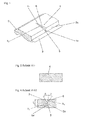
Fig. 1 eine Schrägansicht eines Abschnittes eines Profilbandes mit einer erfindungsgemäß ausgeführten Querrille, -
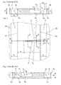
Fig. 2 eine Draufsicht auf den Abschnitt des Profilbandes ausFig. 1 , -
Fig. 3 eine Schnittdarstellung gemäß der Schnittlinie 111-111 derFig. 2 , -
Fig. 4 eine Schnittdarstellung gemäß der Schnittlinie IV-IV derFig. 2 , -
Fig 5 eine Schnittdarstellung gemäß der Schnittlinie V-V derFig. 2 , -
Fig. 6 eine Schnittdarstellung gemäß der Schnittlinie VI-VI derFig. 2 , -
Fig. 7 eine Ansicht eines Abschnittes einer das Profilband begrenzenden Rillenwand in Richtung des Pfeiles P derFig. 2 und -
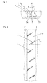
Fig. 8 eine Draufsicht auf einen Umfangsabschnitt eines Profilbandes mit mehreren gemäß der Erfindung ausgeführten Querrillen. - Die
Figuren 1 ,2 und8 zeigen jeweils einen in Umfangsrichtung eines Laufstreifenprofils eines PKW-Fahrzeugluftreifens in radialer Bauart verlaufenden Abschnitt eines Profilbandes 1. Das Profilband 1 weist eine Breite von insbesondere 2 cm bis 3,5 cm auf ist von je einer das Laufstreifenprofil in Umfangsrichtung gerade umlaufenden Umfangsrille 2, 3 begrenzt. - Seitlich der Umfangsrillen 2, 3 schließen weitere Profilpositive an, die in
Fig. 2 lediglich angedeutet sind. Diese Profilpositive können ebenfalls Profilbänder, mit oder ohne erfindungsgemäß ausgeführten Querrillen, oder Profilblockreihen, welche in an sich bekannter Weise ausgeführt sind, sein. Die inFig. 1 undFig. 2 links vom Profilband 1 verlaufende Umfangsrille 2 ist, wie es beispielsweiseFig. 3 zeigt, von zwei in radialer Richtung R oder im Wesentlichen in radialer Richtung R verlaufenden Rillenwänden 2b und 2c und einem im Querschnitt in axialer Richtung verlaufenden Rillengrund 2a begrenzt. Der Rillengrund 2a befindet sich in der für den betreffenden Fahrzeugluftreifen vorgesehenen maximalen Profiltiefe TP, die Öffnungsbreite b2 der Umfangsrille 2 an der Oberfläche des Profilbandes 1 entspricht der Breite des Nutgrundes 2a. Die inFig. 1 undFig. 2 rechts vom Profilband 1 verlaufende Umfangsrille 3 ist hier beispielhaft jene, in welche eine in diesen Figuren gezeigte Querrille 4 mündet. Die Umfangsrille 3 weist, wie es insbesondereFig. 3 zu entnehmen ist, einen sich im Querschnitt in axialer Richtung erstreckenden Rillengrund 3a und zwei Rillenwände 3b, 3c auf. Die dem Profilband 1 gegenüberliegende Rillenwand 3b verläuft in radialer Richtung R. Die Rillenwand 3c ist jene, in welche die Querrille 4 mündet und ist gegenüber der radialen Richtung geringfügig, insbesondere um einen Winkel von 1° bis 10° geneigt, derart, dass die Öffnungsbreite b3 der Umfangsrille 3 an der Oberfläche des Profilbandes 1 eine größere axiale Erstreckung aufweist als der Rillengrund 3a. Die Breite der Umfangsrillen 2, 3 am Rillengrund 2a, 3a beträgt, wie es für derartige Umfangsrillen üblich ist, zwischen 6 mm und 18 mm, die maximale Profiltiefe TP beträgt je nach Reifentyp und Reifendimension üblicherweise zwischen 6 mm und 8,5 mm. - In
Fig. 1 undFig. 2 erstreckt sich die Querrille 4 beispielhaft in axialer Richtung. Wie insbesondereFig. 8 zeigt, können erfindungsgemäß ausgeführte Querrillen 4 alternativ unter einem spitzen Winkel α zur axialen Richtung verlaufen, welcher höchstens 50°, insbesondere bis zu 35°, beträgt. InFig. 8 beträgt der Winkel α in der Größenordnung von 30°. Der Winkel α wird zwischen der Mittellinie a in der Erstreckungsrichtung einer Basisrille 5 und der axialen Richtung ermittelt. An der Oberfläche des Profilbandes 1 weist die Querrille 4 Begrenzungskanten k1, k2 auf, welche in Draufsicht im Wesentlichen die Seiten eines langgestreckten, gleichseitigen Dreieckes bilden, dessen kleinster Winkel sich am Ende der Querrille 4 im Profilband 1 befindet, sodass die Breite der Querrillen 4 in Richtung Umfangsrille 3 größer wird. Die Begrenzungskante k1 schließt mit der Mittellinie a einen Winkel β1 ein, welcher zwischen 5° und 15° beträgt, die Begrenzungskante k2 schließt mit der Mittellinie a einen Winkel β2 ein, welcher um bis zu 5° größer ist als β1. Das laufstreifeninnenseitige Ende der Querrille 4 befindet sich in einem in axialer Richtung ermittelten Abstand n von der Umfangsrille 2, welcher mindestens 5 mm beträgt. Die Querrille 4 selbst weist eine Erstreckungslänge 1 auf, welche an der Oberfläche des Profilbandes 1 ermittelt wird, und in der Größenordnung von 12 mm bis 25 mm beträgt. - Die Querrille 4 weist in Kombination die bereits erwähnte Basisrille 5 und zwei radial außerhalb der Basisrille 5 ausgebildete Rillenflanken 6, 7 auf, welche die Querrille 4 im Querschnitt trichterförmig zur Oberfläche des Profilbandes 1 verbreitern. Die Basisrille 5 befindet sich im radial inneren Bereich der Querrille 4 und erstreckt sich von der Umfangsrille 3 geradlinig in das Profilband 1 über eine Erstreckungslänge l1 von 50 % bis 80 % der Erstreckungslänge l. Der Basisrillengrund 5c befindet sich über die Erstreckungslänge l im Wesentlichen in einer konstanten Tiefe TE (
Fig. 7 ), welche dem radialen Abstand des Einschnittgrundes 5c zur Oberfläche des Profilbandes 1 entspricht. Die Basisrille 5 weist eine konstante Breite von 0,8 mm bis 1,5 mm und zwei parallel zueinander verlaufende Basisrillenwände 5a, 5b auf. Die radiale Erstreckung der Basisrille 5 wird von der radialen Erstreckung der Basisrillenwand 5a bestimmt, die mit der Rillenflanke 7 eine gemeinsame Kante k3 besitzt, die, wie esFig. 5 zeigt, vom inneren Ende bis zur Rillenwand 3c "abfällt" und deren radialer Abstand c2 zur Oberfläche des Profilbandes 1 an der Rillenwand 3c 5 mm bis 7 mm und an ihrem inneren Ende etwa 1 mm beträgt. Die Basisrillenwand 5b besitzt mit der Rillenflanke 6 eine gemeinsame Kante k4, welche ebenfalls von ihrem inneren Ende zur Rillenwand 3c "abfällt" und deren radialer Abstand c1 zur Oberfläche des Profilbandes 1 an der Rillenwand 3c 2 mm bis 3 mm, an ihrem inneren Ende etwa 1 mm beträgt. Die beiden Rillenflanken 6, 7 verlaufen somit, im Rillenquerschnitt betrachtet, asymmetrisch zur Mittellinie a und ferner über das Ende der Basisrille 5 im Profilband 1 hinaus bis zum Schnittpunkt der Begrenzungskanten k1 und k2 an der Oberfläche des Profilbandes 1. Mit der radialen Richtung schließen die Rillenflanken 6, 7 Winkel β, γ ein, die zwischen 30° und 70° gewählt werden und übereinstimmend groß sein können. Bevorzugt ist eine Ausführungsform, bei welcher der Winkel γ der flächenmäßig kleineren Rillenflanke 6 größer ist, insbesondere um mindestens 3°, als der Winkel β der Rillenflanke 7. -
Fig. 8 zeigt ein Profilband 1', welches von in Umfangsrichtung umlaufenden Umfangsrillen 2', 3' begrenzt ist, welche analog zur Umfangsrille 3 ausgebildet sind. Von den Umfangsrillen 2', 3' erstrecken sich abwechselnd Querrillen 4 in das Profilband 1'. Die Querrillen 4 sind gegenüber der axialen Richtung unter dem Winkel α von etwa 30° geneigt. Bei der gezeigten Ausführungsform verlaufen sämtliche Querrillen 4 übereinstimmend schräg zur axialen Richtung. - Erfindungsgemäß ausgeführte Querrillen können auch in Profilblöcken vorgesehen werden. Die Querrillen können in Profilbändern auf spezielle Weise angeordnet werden. So ist es beispielsweise möglich, in einem Profilband zur axialen Richtung geneigt angeordnete Querrillen mit in axialer Richtung verlaufenden Querrillen zu kombinieren, beispielsweise auch bei einer abwechselnden Anordnung in Umfangsrichtung.
-
- 1
- Profilband
- 1'
- Profilband
- 2
- Umfangsrille
- 2'
- Umfangsrille
- 2a
- Rillengrund
- 2b
- Rillenwand
- 2c
- Rillenwand
- 3
- Umfangsrille
- 3'
- Umfangsrille
- 3a
- Rillengrund
- 3b
- Rillenwand
- 3c
- Rillenwand
- 4
- Querrille
- 5
- Basisrille
- 5a
- Basisrillenwand
- 5b
- Basisrillenwand
- 5c
- Basisrillengrund
- 6
- Rillenwand
- 7
- Rillenwand
- a
- Mittellinie
- b2
- Öffnungsbreite
- b3
- Öffnungsbreite
- c1
- Abstand
- c2
- Abstand
- k1
- Begrenzungskante
- k2
- Begrenzungskante
- k3
- Kante
- k4
- Kante
- l
- Erstreckungslänge
- l1
- Erstreckungslänge
- n
- Abstand
- E
- Einschnittmittelebene
- TE
- Einschnitttiefe
- TP
- Profiltiefe
- α
- Winkel
- β
- Winkel
- β1
- Winkel
- β2
- Winkel
- γ
- Winkel
Claims (12)
- Fahrzeugluftreifen mit einem Laufstreifenprofil, welches durch Umfangsrillen (2, 3, 2', 3') in in Umfangsrichtung umlaufende Profilpositive, wie Profilbänder und/oder Profilblockreihen, gegliedert ist, wobei zumindest ein Profilpositiv (1, 1') vorgesehen ist, in welchem Querrillen (4) angeordnet sind, die in eine das Profilpositiv begrenzende Umfangsrille (3) münden und deren Enden sich innerhalb des Profilbandes (1, 1') befinden, wobei die Querrillen (4) an der Oberfläche des Profilpositives von Begrenzungskanten (k1, k2) begrenzt sind, deren gegenseitiger Abstand in Richtung Umfangsrille (3) größer wird,
dadurch gekennzeichnet,
dass die Querrillen (4) jeweils in ihrem radial inneren Bereich eine zwischen 0,8 mm und 1,5 mm breite gerade verlaufende Basisrille (5) und in ihrem radial äußeren Bereich zwischen den Begrenzungskanten (k1, k2) und der Basisrille (5) verlaufende Rillenflanken (6, 7) aufweist, wobei die Basisrille (5) über ihre Erstreckung zumindest im Wesentlichen in einer konstanten Tiefe verläuft, die radiale Erstreckung der Basisrille (5) jedoch vom inneren Endbereich der Querrille (4) in Richtung Umfangsrille (3) kontinuierlich geringer wird, und wobei die eine Basisrillenwand (5b) in radialer Richtung über die andere Basisrillenwand (5a) hinausragt, so dass die zwischen den
Basisrillenwänden (5a, 5b) und den jeweiligen Rillenflanken (6, 7) gebildeten gemeinsamen Kanten auf unterschiedlichen radialen Niveaus verlaufen. - Fahrzeugluftreifen nach Anspruch 1 oder 2, dadurch gekennzeichnet, dass der radiale Abstand (c2) der zwischen der einen Basisrillenwand (5a) und der anschließenden Rillenflanke (7) gebildeten gemeinsamen Kante (k3) zur Oberfläche des Profilpositives (1) an der Umfangsrille (3) 5 mm bis 7 mm beträgt.
- Fahrzeugluftreifen nach Anspruch 1 oder 2, dadurch gekennzeichnet, dass der radiale Abstand (c1) der zwischen der über die Basisrille (5) hinausragenden anderen Basisrillenwand (5b) und der zweiten Rillenflanke (6) gebildeten gemeinsamen Kante (k4) zur Oberfläche des Profilpositives (1) an der Umfangsrille (3) 2 mm bis 3 mm beträgt.
- Fahrzeugluftreifen nach einem der Ansprüche 1 bis 3, dadurch gekennzeichnet, dass die gemeinsamen Kanten (k3, k4) am inneren Ende der Basisrille (5) einen etwa gleich großen radialen Abstand zur Oberfläche des Profilpositives (1) aufweisen, welcher kleiner ist als die radialen Abstände (c1, c2) an der Umfangsrille (3) und vorzugsweise höchstens 1 mm beträgt.
- Fahrzeugluftreifen nach einem der Ansprüche 1 bis 5, dadurch gekennzeichnet, dass die Rillenflanken (6, 7) unter zumindest im Wesentlichen gleich großen Winkeln (β, γ) relativ zur radialen Richtung geneigte Flächen sind.
- Fahrzeugluftreifen nach einem der Ansprüche 1 bis 5, dadurch gekennzeichnet, dass die an der Oberfläche des Profilpositives (1, 1') verlaufenden Begrenzungskanten (k1, k2) der Querrille (4) am Querrillenende spitz zusammenlaufen.
- Fahrzeugluftreifen nach einem der Ansprüche 1 bis 6, dadurch gekennzeichnet, dass die Rillenflanken (6, 7) in Erstreckungsrichtung der Basisrille (5) über deren Ende im Profilpositiv (1, 1') hinaus bis zum Schnittpunkt der Begrenzungskanten (k1, k2) verlaufen.
- Fahrzeugluftreifen nach einem der Ansprüche 1 bis 7, dadurch gekennzeichnet, dass die an der Oberfläche des Profilpositives (1, 1') vorgesehenen Begrenzungskanten (k1, k2) unter unterschiedlich großen spitzen Winkeln zur Mittellinie der Basisrille (5) verlaufen.
- Fahrzeugluftreifen nach einem der Ansprüche 1 bis 8, dadurch gekennzeichnet, dass die Basisrille (5) einer Erstreckungslänge aufweist, die zwischen 50 % und 80% der Erstreckungslänge der Querrille (4) entspricht.
- Fahrzeugluftreifen nach einem der Ansprüche 1 bis 9, dadurch gekennzeichnet, dass im Laufstreifen zumindest ein beidseitig von Umfangsrillen (2', 3') begrenztes Profilband (1') vorgesehen ist, in welches die Querrillen (4) in Umfangsrichtung abwechselnd einmünden.
- Fahrzeugluftreifen nach einem der Ansprüche 1 bis 10, dadurch gekennzeichnet, dass die Querrillen (4) unter einem Winkel von bis zu 50° zur axialen Richtung verlaufen.
- Fahrzeugluftreifen nach einem der Ansprüche 1 bis 11, dadurch gekennzeichnet, dass im Laufstreifen zumindest ein Profilband vorgesehen ist, in welchem sämtliche Querrillen (4) unter im Wesentlichen übereinstimmenden Winkeln zur axialen Richtung verlaufen.
Applications Claiming Priority (1)
| Application Number | Priority Date | Filing Date | Title |
|---|---|---|---|
| DE201210108847 DE102012108847A1 (de) | 2012-09-20 | 2012-09-20 | Fahrzeugluftreifen |
Publications (2)
| Publication Number | Publication Date |
|---|---|
| EP2711200A1 true EP2711200A1 (de) | 2014-03-26 |
| EP2711200B1 EP2711200B1 (de) | 2017-01-18 |
Family
ID=48949072
Family Applications (1)
| Application Number | Title | Priority Date | Filing Date |
|---|---|---|---|
| EP13180011.2A Not-in-force EP2711200B1 (de) | 2012-09-20 | 2013-08-12 | Fahrzeugluftreifen |
Country Status (2)
| Country | Link |
|---|---|
| EP (1) | EP2711200B1 (de) |
| DE (1) | DE102012108847A1 (de) |
Cited By (4)
| Publication number | Priority date | Publication date | Assignee | Title |
|---|---|---|---|---|
| CN106347032A (zh) * | 2015-07-13 | 2017-01-25 | 住友橡胶工业株式会社 | 充气轮胎 |
| US10703142B2 (en) | 2014-11-11 | 2020-07-07 | Bridgestone Corporation | Pneumatic tire |
| CN113043793A (zh) * | 2019-12-27 | 2021-06-29 | 住友橡胶工业株式会社 | 轮胎 |
| EP4197818A1 (de) * | 2021-12-17 | 2023-06-21 | Sumitomo Rubber Industries, Ltd. | Reifen |
Families Citing this family (4)
| Publication number | Priority date | Publication date | Assignee | Title |
|---|---|---|---|---|
| US10780743B2 (en) * | 2017-03-16 | 2020-09-22 | Sumitomo Rubber Industries, Ltd. | Tire |
| JP7144279B2 (ja) * | 2018-10-22 | 2022-09-29 | Toyo Tire株式会社 | 空気入りタイヤ |
| JP7622416B2 (ja) * | 2020-12-16 | 2025-01-28 | 住友ゴム工業株式会社 | タイヤ |
| CN114683778B (zh) * | 2020-12-28 | 2026-01-30 | 住友橡胶工业株式会社 | 轮胎 |
Citations (3)
| Publication number | Priority date | Publication date | Assignee | Title |
|---|---|---|---|---|
| GB2038729A (en) * | 1978-12-22 | 1980-07-30 | Pirelli | Tyre tread |
| EP1580032A1 (de) * | 2004-03-26 | 2005-09-28 | Continental Aktiengesellschaft | Fahrzeugluftreifen |
| EP2281698A1 (de) * | 2009-08-03 | 2011-02-09 | Sumitomo Rubber Industries, Ltd. | Luftreifen |
-
2012
- 2012-09-20 DE DE201210108847 patent/DE102012108847A1/de not_active Withdrawn
-
2013
- 2013-08-12 EP EP13180011.2A patent/EP2711200B1/de not_active Not-in-force
Patent Citations (3)
| Publication number | Priority date | Publication date | Assignee | Title |
|---|---|---|---|---|
| GB2038729A (en) * | 1978-12-22 | 1980-07-30 | Pirelli | Tyre tread |
| EP1580032A1 (de) * | 2004-03-26 | 2005-09-28 | Continental Aktiengesellschaft | Fahrzeugluftreifen |
| EP2281698A1 (de) * | 2009-08-03 | 2011-02-09 | Sumitomo Rubber Industries, Ltd. | Luftreifen |
Cited By (7)
| Publication number | Priority date | Publication date | Assignee | Title |
|---|---|---|---|---|
| US10703142B2 (en) | 2014-11-11 | 2020-07-07 | Bridgestone Corporation | Pneumatic tire |
| CN106347032A (zh) * | 2015-07-13 | 2017-01-25 | 住友橡胶工业株式会社 | 充气轮胎 |
| CN106347032B (zh) * | 2015-07-13 | 2019-09-24 | 住友橡胶工业株式会社 | 充气轮胎 |
| CN113043793A (zh) * | 2019-12-27 | 2021-06-29 | 住友橡胶工业株式会社 | 轮胎 |
| EP4197818A1 (de) * | 2021-12-17 | 2023-06-21 | Sumitomo Rubber Industries, Ltd. | Reifen |
| JP2023090288A (ja) * | 2021-12-17 | 2023-06-29 | 住友ゴム工業株式会社 | タイヤ |
| US12097726B2 (en) | 2021-12-17 | 2024-09-24 | Sumitomo Rubber Industries, Ltd. | Tire |
Also Published As
| Publication number | Publication date |
|---|---|
| EP2711200B1 (de) | 2017-01-18 |
| DE102012108847A1 (de) | 2014-03-20 |
Similar Documents
| Publication | Publication Date | Title |
|---|---|---|
| EP2711200B1 (de) | Fahrzeugluftreifen | |
| EP2892736B1 (de) | Fahrzeugluftreifen | |
| EP3256333B1 (de) | Fahrzeugluftreifen | |
| DE102012109712A1 (de) | Fahrzeugluftreifen | |
| DE102015224288A1 (de) | Fahrzeugluftreifen | |
| EP1238827B1 (de) | Reifenprofil | |
| EP3169536B1 (de) | Fahrzeugluftreifen | |
| EP3300926B1 (de) | Fahrzeugluftreifen | |
| EP2900489B1 (de) | Fahrzeugluftreifen | |
| EP3519208B1 (de) | Fahrzeugluftreifen | |
| EP3256335B1 (de) | Fahrzeugluftreifen | |
| DE102018217712A1 (de) | Fahrzeugluftreifen | |
| EP3160775B1 (de) | Fahrzeugluftreifen | |
| EP3300925A1 (de) | Fahrzeugluftreifen | |
| DE102008029658A1 (de) | Fahrzeugluftreifen | |
| WO2016091417A1 (de) | Fahrzeugluftreifen | |
| EP3112187B1 (de) | Fahrzeugluftreifen | |
| WO2020114672A1 (de) | Laufstreifenprofil eines fahrzeugreifens | |
| EP4281297B1 (de) | Fahrzeugluftreifen | |
| EP2897815B1 (de) | Fahrzeugluftreifen | |
| EP3870461B1 (de) | Fahrzeugluftreifen | |
| DE102019206679A1 (de) | Fahrzeugluftreifen | |
| EP4342686A1 (de) | Fahrzeugreifen | |
| WO2023208287A1 (de) | Fahrzeugreifen | |
| EP3551474A1 (de) | Fahrzeugluftreifen |
Legal Events
| Date | Code | Title | Description |
|---|---|---|---|
| PUAI | Public reference made under article 153(3) epc to a published international application that has entered the european phase |
Free format text: ORIGINAL CODE: 0009012 |
|
| AK | Designated contracting states |
Kind code of ref document: A1 Designated state(s): AL AT BE BG CH CY CZ DE DK EE ES FI FR GB GR HR HU IE IS IT LI LT LU LV MC MK MT NL NO PL PT RO RS SE SI SK SM TR |
|
| AX | Request for extension of the european patent |
Extension state: BA ME |
|
| 17P | Request for examination filed |
Effective date: 20140926 |
|
| RBV | Designated contracting states (corrected) |
Designated state(s): AL AT BE BG CH CY CZ DE DK EE ES FI FR GB GR HR HU IE IS IT LI LT LU LV MC MK MT NL NO PL PT RO RS SE SI SK SM TR |
|
| 17Q | First examination report despatched |
Effective date: 20160503 |
|
| GRAP | Despatch of communication of intention to grant a patent |
Free format text: ORIGINAL CODE: EPIDOSNIGR1 |
|
| INTG | Intention to grant announced |
Effective date: 20160920 |
|
| GRAS | Grant fee paid |
Free format text: ORIGINAL CODE: EPIDOSNIGR3 |
|
| GRAA | (expected) grant |
Free format text: ORIGINAL CODE: 0009210 |
|
| AK | Designated contracting states |
Kind code of ref document: B1 Designated state(s): AL AT BE BG CH CY CZ DE DK EE ES FI FR GB GR HR HU IE IS IT LI LT LU LV MC MK MT NL NO PL PT RO RS SE SI SK SM TR |
|
| REG | Reference to a national code |
Ref country code: GB Ref legal event code: FG4D Free format text: NOT ENGLISH |
|
| REG | Reference to a national code |
Ref country code: CH Ref legal event code: EP |
|
| REG | Reference to a national code |
Ref country code: AT Ref legal event code: REF Ref document number: 862680 Country of ref document: AT Kind code of ref document: T Effective date: 20170215 |
|
| REG | Reference to a national code |
Ref country code: IE Ref legal event code: FG4D Free format text: LANGUAGE OF EP DOCUMENT: GERMAN |
|
| REG | Reference to a national code |
Ref country code: DE Ref legal event code: R096 Ref document number: 502013006134 Country of ref document: DE |
|
| REG | Reference to a national code |
Ref country code: NL Ref legal event code: MP Effective date: 20170118 |
|
| REG | Reference to a national code |
Ref country code: LT Ref legal event code: MG4D |
|
| PG25 | Lapsed in a contracting state [announced via postgrant information from national office to epo] |
Ref country code: NL Free format text: LAPSE BECAUSE OF FAILURE TO SUBMIT A TRANSLATION OF THE DESCRIPTION OR TO PAY THE FEE WITHIN THE PRESCRIBED TIME-LIMIT Effective date: 20170118 |
|
| PG25 | Lapsed in a contracting state [announced via postgrant information from national office to epo] |
Ref country code: IS Free format text: LAPSE BECAUSE OF FAILURE TO SUBMIT A TRANSLATION OF THE DESCRIPTION OR TO PAY THE FEE WITHIN THE PRESCRIBED TIME-LIMIT Effective date: 20170518 Ref country code: HR Free format text: LAPSE BECAUSE OF FAILURE TO SUBMIT A TRANSLATION OF THE DESCRIPTION OR TO PAY THE FEE WITHIN THE PRESCRIBED TIME-LIMIT Effective date: 20170118 Ref country code: LT Free format text: LAPSE BECAUSE OF FAILURE TO SUBMIT A TRANSLATION OF THE DESCRIPTION OR TO PAY THE FEE WITHIN THE PRESCRIBED TIME-LIMIT Effective date: 20170118 Ref country code: NO Free format text: LAPSE BECAUSE OF FAILURE TO SUBMIT A TRANSLATION OF THE DESCRIPTION OR TO PAY THE FEE WITHIN THE PRESCRIBED TIME-LIMIT Effective date: 20170418 Ref country code: GR Free format text: LAPSE BECAUSE OF FAILURE TO SUBMIT A TRANSLATION OF THE DESCRIPTION OR TO PAY THE FEE WITHIN THE PRESCRIBED TIME-LIMIT Effective date: 20170419 Ref country code: FI Free format text: LAPSE BECAUSE OF FAILURE TO SUBMIT A TRANSLATION OF THE DESCRIPTION OR TO PAY THE FEE WITHIN THE PRESCRIBED TIME-LIMIT Effective date: 20170118 |
|
| REG | Reference to a national code |
Ref country code: FR Ref legal event code: PLFP Year of fee payment: 5 |
|
| PG25 | Lapsed in a contracting state [announced via postgrant information from national office to epo] |
Ref country code: BG Free format text: LAPSE BECAUSE OF FAILURE TO SUBMIT A TRANSLATION OF THE DESCRIPTION OR TO PAY THE FEE WITHIN THE PRESCRIBED TIME-LIMIT Effective date: 20170418 Ref country code: LV Free format text: LAPSE BECAUSE OF FAILURE TO SUBMIT A TRANSLATION OF THE DESCRIPTION OR TO PAY THE FEE WITHIN THE PRESCRIBED TIME-LIMIT Effective date: 20170118 Ref country code: ES Free format text: LAPSE BECAUSE OF FAILURE TO SUBMIT A TRANSLATION OF THE DESCRIPTION OR TO PAY THE FEE WITHIN THE PRESCRIBED TIME-LIMIT Effective date: 20170118 Ref country code: SE Free format text: LAPSE BECAUSE OF FAILURE TO SUBMIT A TRANSLATION OF THE DESCRIPTION OR TO PAY THE FEE WITHIN THE PRESCRIBED TIME-LIMIT Effective date: 20170118 Ref country code: PL Free format text: LAPSE BECAUSE OF FAILURE TO SUBMIT A TRANSLATION OF THE DESCRIPTION OR TO PAY THE FEE WITHIN THE PRESCRIBED TIME-LIMIT Effective date: 20170118 Ref country code: RS Free format text: LAPSE BECAUSE OF FAILURE TO SUBMIT A TRANSLATION OF THE DESCRIPTION OR TO PAY THE FEE WITHIN THE PRESCRIBED TIME-LIMIT Effective date: 20170118 Ref country code: PT Free format text: LAPSE BECAUSE OF FAILURE TO SUBMIT A TRANSLATION OF THE DESCRIPTION OR TO PAY THE FEE WITHIN THE PRESCRIBED TIME-LIMIT Effective date: 20170518 |
|
| REG | Reference to a national code |
Ref country code: DE Ref legal event code: R097 Ref document number: 502013006134 Country of ref document: DE |
|
| PG25 | Lapsed in a contracting state [announced via postgrant information from national office to epo] |
Ref country code: SK Free format text: LAPSE BECAUSE OF FAILURE TO SUBMIT A TRANSLATION OF THE DESCRIPTION OR TO PAY THE FEE WITHIN THE PRESCRIBED TIME-LIMIT Effective date: 20170118 Ref country code: RO Free format text: LAPSE BECAUSE OF FAILURE TO SUBMIT A TRANSLATION OF THE DESCRIPTION OR TO PAY THE FEE WITHIN THE PRESCRIBED TIME-LIMIT Effective date: 20170118 Ref country code: CZ Free format text: LAPSE BECAUSE OF FAILURE TO SUBMIT A TRANSLATION OF THE DESCRIPTION OR TO PAY THE FEE WITHIN THE PRESCRIBED TIME-LIMIT Effective date: 20170118 Ref country code: EE Free format text: LAPSE BECAUSE OF FAILURE TO SUBMIT A TRANSLATION OF THE DESCRIPTION OR TO PAY THE FEE WITHIN THE PRESCRIBED TIME-LIMIT Effective date: 20170118 |
|
| PLBE | No opposition filed within time limit |
Free format text: ORIGINAL CODE: 0009261 |
|
| STAA | Information on the status of an ep patent application or granted ep patent |
Free format text: STATUS: NO OPPOSITION FILED WITHIN TIME LIMIT |
|
| PG25 | Lapsed in a contracting state [announced via postgrant information from national office to epo] |
Ref country code: DK Free format text: LAPSE BECAUSE OF FAILURE TO SUBMIT A TRANSLATION OF THE DESCRIPTION OR TO PAY THE FEE WITHIN THE PRESCRIBED TIME-LIMIT Effective date: 20170118 Ref country code: SM Free format text: LAPSE BECAUSE OF FAILURE TO SUBMIT A TRANSLATION OF THE DESCRIPTION OR TO PAY THE FEE WITHIN THE PRESCRIBED TIME-LIMIT Effective date: 20170118 |
|
| 26N | No opposition filed |
Effective date: 20171019 |
|
| PG25 | Lapsed in a contracting state [announced via postgrant information from national office to epo] |
Ref country code: SI Free format text: LAPSE BECAUSE OF FAILURE TO SUBMIT A TRANSLATION OF THE DESCRIPTION OR TO PAY THE FEE WITHIN THE PRESCRIBED TIME-LIMIT Effective date: 20170118 |
|
| REG | Reference to a national code |
Ref country code: CH Ref legal event code: PL |
|
| PG25 | Lapsed in a contracting state [announced via postgrant information from national office to epo] |
Ref country code: MC Free format text: LAPSE BECAUSE OF FAILURE TO SUBMIT A TRANSLATION OF THE DESCRIPTION OR TO PAY THE FEE WITHIN THE PRESCRIBED TIME-LIMIT Effective date: 20170118 |
|
| PG25 | Lapsed in a contracting state [announced via postgrant information from national office to epo] |
Ref country code: LI Free format text: LAPSE BECAUSE OF NON-PAYMENT OF DUE FEES Effective date: 20170831 Ref country code: CH Free format text: LAPSE BECAUSE OF NON-PAYMENT OF DUE FEES Effective date: 20170831 |
|
| REG | Reference to a national code |
Ref country code: IE Ref legal event code: MM4A |
|
| REG | Reference to a national code |
Ref country code: BE Ref legal event code: MM Effective date: 20170831 |
|
| PG25 | Lapsed in a contracting state [announced via postgrant information from national office to epo] |
Ref country code: LU Free format text: LAPSE BECAUSE OF NON-PAYMENT OF DUE FEES Effective date: 20170812 |
|
| PG25 | Lapsed in a contracting state [announced via postgrant information from national office to epo] |
Ref country code: IE Free format text: LAPSE BECAUSE OF NON-PAYMENT OF DUE FEES Effective date: 20170812 |
|
| REG | Reference to a national code |
Ref country code: FR Ref legal event code: PLFP Year of fee payment: 6 |
|
| PG25 | Lapsed in a contracting state [announced via postgrant information from national office to epo] |
Ref country code: BE Free format text: LAPSE BECAUSE OF NON-PAYMENT OF DUE FEES Effective date: 20170831 |
|
| PG25 | Lapsed in a contracting state [announced via postgrant information from national office to epo] |
Ref country code: MT Free format text: LAPSE BECAUSE OF FAILURE TO SUBMIT A TRANSLATION OF THE DESCRIPTION OR TO PAY THE FEE WITHIN THE PRESCRIBED TIME-LIMIT Effective date: 20170118 |
|
| PG25 | Lapsed in a contracting state [announced via postgrant information from national office to epo] |
Ref country code: HU Free format text: LAPSE BECAUSE OF FAILURE TO SUBMIT A TRANSLATION OF THE DESCRIPTION OR TO PAY THE FEE WITHIN THE PRESCRIBED TIME-LIMIT; INVALID AB INITIO Effective date: 20130812 |
|
| REG | Reference to a national code |
Ref country code: AT Ref legal event code: MM01 Ref document number: 862680 Country of ref document: AT Kind code of ref document: T Effective date: 20180812 |
|
| PG25 | Lapsed in a contracting state [announced via postgrant information from national office to epo] |
Ref country code: CY Free format text: LAPSE BECAUSE OF NON-PAYMENT OF DUE FEES Effective date: 20170118 |
|
| PG25 | Lapsed in a contracting state [announced via postgrant information from national office to epo] |
Ref country code: MK Free format text: LAPSE BECAUSE OF FAILURE TO SUBMIT A TRANSLATION OF THE DESCRIPTION OR TO PAY THE FEE WITHIN THE PRESCRIBED TIME-LIMIT Effective date: 20170118 |
|
| PG25 | Lapsed in a contracting state [announced via postgrant information from national office to epo] |
Ref country code: AT Free format text: LAPSE BECAUSE OF NON-PAYMENT OF DUE FEES Effective date: 20180812 |
|
| PG25 | Lapsed in a contracting state [announced via postgrant information from national office to epo] |
Ref country code: TR Free format text: LAPSE BECAUSE OF FAILURE TO SUBMIT A TRANSLATION OF THE DESCRIPTION OR TO PAY THE FEE WITHIN THE PRESCRIBED TIME-LIMIT Effective date: 20170118 |
|
| PG25 | Lapsed in a contracting state [announced via postgrant information from national office to epo] |
Ref country code: AL Free format text: LAPSE BECAUSE OF FAILURE TO SUBMIT A TRANSLATION OF THE DESCRIPTION OR TO PAY THE FEE WITHIN THE PRESCRIBED TIME-LIMIT Effective date: 20170118 |
|
| PGFP | Annual fee paid to national office [announced via postgrant information from national office to epo] |
Ref country code: IT Payment date: 20220825 Year of fee payment: 10 Ref country code: GB Payment date: 20220822 Year of fee payment: 10 Ref country code: DE Payment date: 20220601 Year of fee payment: 10 |
|
| PGFP | Annual fee paid to national office [announced via postgrant information from national office to epo] |
Ref country code: FR Payment date: 20220823 Year of fee payment: 10 |
|
| REG | Reference to a national code |
Ref country code: DE Ref legal event code: R119 Ref document number: 502013006134 Country of ref document: DE |
|
| GBPC | Gb: european patent ceased through non-payment of renewal fee |
Effective date: 20230812 |
|
| PG25 | Lapsed in a contracting state [announced via postgrant information from national office to epo] |
Ref country code: GB Free format text: LAPSE BECAUSE OF NON-PAYMENT OF DUE FEES Effective date: 20230812 |
|
| PG25 | Lapsed in a contracting state [announced via postgrant information from national office to epo] |
Ref country code: IT Free format text: LAPSE BECAUSE OF NON-PAYMENT OF DUE FEES Effective date: 20230812 Ref country code: GB Free format text: LAPSE BECAUSE OF NON-PAYMENT OF DUE FEES Effective date: 20230812 Ref country code: FR Free format text: LAPSE BECAUSE OF NON-PAYMENT OF DUE FEES Effective date: 20230831 Ref country code: DE Free format text: LAPSE BECAUSE OF NON-PAYMENT OF DUE FEES Effective date: 20240301 |