EP2710264B1 - Modularer elektrischer verdichter mit eingebauter sicherungsvorrichtung - Google Patents
Modularer elektrischer verdichter mit eingebauter sicherungsvorrichtung Download PDFInfo
- Publication number
- EP2710264B1 EP2710264B1 EP12717187.4A EP12717187A EP2710264B1 EP 2710264 B1 EP2710264 B1 EP 2710264B1 EP 12717187 A EP12717187 A EP 12717187A EP 2710264 B1 EP2710264 B1 EP 2710264B1
- Authority
- EP
- European Patent Office
- Prior art keywords
- housing
- motor
- inverter
- motor housing
- compression
- Prior art date
- Legal status (The legal status is an assumption and is not a legal conclusion. Google has not performed a legal analysis and makes no representation as to the accuracy of the status listed.)
- Not-in-force
Links
- 230000006835 compression Effects 0.000 claims description 44
- 238000007906 compression Methods 0.000 claims description 44
- 239000003507 refrigerant Substances 0.000 claims description 12
- 238000010079 rubber tapping Methods 0.000 claims description 7
- 239000012530 fluid Substances 0.000 description 8
- 238000004519 manufacturing process Methods 0.000 description 8
- 239000002826 coolant Substances 0.000 description 7
- 238000004378 air conditioning Methods 0.000 description 3
- 238000001029 thermal curing Methods 0.000 description 2
- 229910000838 Al alloy Inorganic materials 0.000 description 1
- XAGFODPZIPBFFR-UHFFFAOYSA-N aluminium Chemical compound [Al] XAGFODPZIPBFFR-UHFFFAOYSA-N 0.000 description 1
- 229910052782 aluminium Inorganic materials 0.000 description 1
- 230000004323 axial length Effects 0.000 description 1
- 230000015572 biosynthetic process Effects 0.000 description 1
- 230000009977 dual effect Effects 0.000 description 1
- 230000012010 growth Effects 0.000 description 1
- 230000002452 interceptive effect Effects 0.000 description 1
- 238000012423 maintenance Methods 0.000 description 1
- 230000002093 peripheral effect Effects 0.000 description 1
- 238000007789 sealing Methods 0.000 description 1
Images


Classifications
-
- F—MECHANICAL ENGINEERING; LIGHTING; HEATING; WEAPONS; BLASTING
- F01—MACHINES OR ENGINES IN GENERAL; ENGINE PLANTS IN GENERAL; STEAM ENGINES
- F01C—ROTARY-PISTON OR OSCILLATING-PISTON MACHINES OR ENGINES
- F01C21/00—Component parts, details or accessories not provided for in groups F01C1/00 - F01C20/00
- F01C21/10—Outer members for co-operation with rotary pistons; Casings
-
- F—MECHANICAL ENGINEERING; LIGHTING; HEATING; WEAPONS; BLASTING
- F04—POSITIVE - DISPLACEMENT MACHINES FOR LIQUIDS; PUMPS FOR LIQUIDS OR ELASTIC FLUIDS
- F04B—POSITIVE-DISPLACEMENT MACHINES FOR LIQUIDS; PUMPS
- F04B17/00—Pumps characterised by combination with, or adaptation to, specific driving engines or motors
- F04B17/03—Pumps characterised by combination with, or adaptation to, specific driving engines or motors driven by electric motors
-
- F—MECHANICAL ENGINEERING; LIGHTING; HEATING; WEAPONS; BLASTING
- F04—POSITIVE - DISPLACEMENT MACHINES FOR LIQUIDS; PUMPS FOR LIQUIDS OR ELASTIC FLUIDS
- F04B—POSITIVE-DISPLACEMENT MACHINES FOR LIQUIDS; PUMPS
- F04B35/00—Piston pumps specially adapted for elastic fluids and characterised by the driving means to their working members, or by combination with, or adaptation to, specific driving engines or motors, not otherwise provided for
- F04B35/04—Piston pumps specially adapted for elastic fluids and characterised by the driving means to their working members, or by combination with, or adaptation to, specific driving engines or motors, not otherwise provided for the means being electric
-
- F—MECHANICAL ENGINEERING; LIGHTING; HEATING; WEAPONS; BLASTING
- F04—POSITIVE - DISPLACEMENT MACHINES FOR LIQUIDS; PUMPS FOR LIQUIDS OR ELASTIC FLUIDS
- F04B—POSITIVE-DISPLACEMENT MACHINES FOR LIQUIDS; PUMPS
- F04B39/00—Component parts, details, or accessories, of pumps or pumping systems specially adapted for elastic fluids, not otherwise provided for in, or of interest apart from, groups F04B25/00 - F04B37/00
- F04B39/12—Casings; Cylinders; Cylinder heads; Fluid connections
- F04B39/121—Casings
-
- F—MECHANICAL ENGINEERING; LIGHTING; HEATING; WEAPONS; BLASTING
- F04—POSITIVE - DISPLACEMENT MACHINES FOR LIQUIDS; PUMPS FOR LIQUIDS OR ELASTIC FLUIDS
- F04B—POSITIVE-DISPLACEMENT MACHINES FOR LIQUIDS; PUMPS
- F04B53/00—Component parts, details or accessories not provided for in, or of interest apart from, groups F04B1/00 - F04B23/00 or F04B39/00 - F04B47/00
- F04B53/22—Arrangements for enabling ready assembly or disassembly
-
- F—MECHANICAL ENGINEERING; LIGHTING; HEATING; WEAPONS; BLASTING
- F04—POSITIVE - DISPLACEMENT MACHINES FOR LIQUIDS; PUMPS FOR LIQUIDS OR ELASTIC FLUIDS
- F04C—ROTARY-PISTON, OR OSCILLATING-PISTON, POSITIVE-DISPLACEMENT MACHINES FOR LIQUIDS; ROTARY-PISTON, OR OSCILLATING-PISTON, POSITIVE-DISPLACEMENT PUMPS
- F04C23/00—Combinations of two or more pumps, each being of rotary-piston or oscillating-piston type, specially adapted for elastic fluids; Pumping installations specially adapted for elastic fluids; Multi-stage pumps specially adapted for elastic fluids
- F04C23/008—Hermetic pumps
-
- H—ELECTRICITY
- H02—GENERATION; CONVERSION OR DISTRIBUTION OF ELECTRIC POWER
- H02K—DYNAMO-ELECTRIC MACHINES
- H02K1/00—Details of the magnetic circuit
- H02K1/06—Details of the magnetic circuit characterised by the shape, form or construction
- H02K1/12—Stationary parts of the magnetic circuit
- H02K1/20—Stationary parts of the magnetic circuit with channels or ducts for flow of cooling medium
-
- F—MECHANICAL ENGINEERING; LIGHTING; HEATING; WEAPONS; BLASTING
- F04—POSITIVE - DISPLACEMENT MACHINES FOR LIQUIDS; PUMPS FOR LIQUIDS OR ELASTIC FLUIDS
- F04C—ROTARY-PISTON, OR OSCILLATING-PISTON, POSITIVE-DISPLACEMENT MACHINES FOR LIQUIDS; ROTARY-PISTON, OR OSCILLATING-PISTON, POSITIVE-DISPLACEMENT PUMPS
- F04C18/00—Rotary-piston pumps specially adapted for elastic fluids
- F04C18/02—Rotary-piston pumps specially adapted for elastic fluids of arcuate-engagement type, i.e. with circular translatory movement of co-operating members, each member having the same number of teeth or tooth-equivalents
- F04C18/0207—Rotary-piston pumps specially adapted for elastic fluids of arcuate-engagement type, i.e. with circular translatory movement of co-operating members, each member having the same number of teeth or tooth-equivalents both members having co-operating elements in spiral form
- F04C18/0215—Rotary-piston pumps specially adapted for elastic fluids of arcuate-engagement type, i.e. with circular translatory movement of co-operating members, each member having the same number of teeth or tooth-equivalents both members having co-operating elements in spiral form where only one member is moving
-
- F—MECHANICAL ENGINEERING; LIGHTING; HEATING; WEAPONS; BLASTING
- F04—POSITIVE - DISPLACEMENT MACHINES FOR LIQUIDS; PUMPS FOR LIQUIDS OR ELASTIC FLUIDS
- F04C—ROTARY-PISTON, OR OSCILLATING-PISTON, POSITIVE-DISPLACEMENT MACHINES FOR LIQUIDS; ROTARY-PISTON, OR OSCILLATING-PISTON, POSITIVE-DISPLACEMENT PUMPS
- F04C2240/00—Components
- F04C2240/80—Other components
- F04C2240/805—Fastening means, e.g. bolts
-
- F—MECHANICAL ENGINEERING; LIGHTING; HEATING; WEAPONS; BLASTING
- F04—POSITIVE - DISPLACEMENT MACHINES FOR LIQUIDS; PUMPS FOR LIQUIDS OR ELASTIC FLUIDS
- F04C—ROTARY-PISTON, OR OSCILLATING-PISTON, POSITIVE-DISPLACEMENT MACHINES FOR LIQUIDS; ROTARY-PISTON, OR OSCILLATING-PISTON, POSITIVE-DISPLACEMENT PUMPS
- F04C2240/00—Components
- F04C2240/80—Other components
- F04C2240/808—Electronic circuits (e.g. inverters) installed inside the machine
-
- H—ELECTRICITY
- H02—GENERATION; CONVERSION OR DISTRIBUTION OF ELECTRIC POWER
- H02K—DYNAMO-ELECTRIC MACHINES
- H02K1/00—Details of the magnetic circuit
- H02K1/06—Details of the magnetic circuit characterised by the shape, form or construction
- H02K1/12—Stationary parts of the magnetic circuit
- H02K1/18—Means for mounting or fastening magnetic stationary parts on to, or to, the stator structures
- H02K1/185—Means for mounting or fastening magnetic stationary parts on to, or to, the stator structures to outer stators
-
- H—ELECTRICITY
- H02—GENERATION; CONVERSION OR DISTRIBUTION OF ELECTRIC POWER
- H02K—DYNAMO-ELECTRIC MACHINES
- H02K11/00—Structural association of dynamo-electric machines with electric components or with devices for shielding, monitoring or protection
- H02K11/30—Structural association with control circuits or drive circuits
- H02K11/33—Drive circuits, e.g. power electronics
-
- H—ELECTRICITY
- H02—GENERATION; CONVERSION OR DISTRIBUTION OF ELECTRIC POWER
- H02K—DYNAMO-ELECTRIC MACHINES
- H02K5/00—Casings; Enclosures; Supports
- H02K5/04—Casings or enclosures characterised by the shape, form or construction thereof
- H02K5/12—Casings or enclosures characterised by the shape, form or construction thereof specially adapted for operating in liquid or gas
-
- H—ELECTRICITY
- H02—GENERATION; CONVERSION OR DISTRIBUTION OF ELECTRIC POWER
- H02K—DYNAMO-ELECTRIC MACHINES
- H02K7/00—Arrangements for handling mechanical energy structurally associated with dynamo-electric machines, e.g. structural association with mechanical driving motors or auxiliary dynamo-electric machines
- H02K7/14—Structural association with mechanical loads, e.g. with hand-held machine tools or fans
Definitions
- the technical sector of the present invention is that of electric compressors equipping a motor vehicle, for example, for the circulation of a refrigerant inside an air conditioning system of the vehicle.
- An electric compressor typically comprises a compression mechanism, driven by an electric motor, to pressurize the coolant in the air conditioning circuit.
- the compressor further comprises an inverter for converting the electrical energy of the vehicle engine into electrical energy suitable for the compressor motor.
- the inverter is adapted to convert a single-phase current into a three-phase current.
- Such compressors are known in the literature, see for example US2002 / 0025265 A1 .
- the document JP2003-343438A discloses an electric compressor (not shown) having a compression housing in which is mounted the compression mechanism, a motor housing in which is mounted the electric motor and an inverter housing in which is mounted the inverter.
- the outer surfaces of the housings comprise fastening flanges adapted to allow the passage of fastening screws.
- the fixing screws thus make it possible to secure the fixing flange of the motor housing to that of the inverter housing.
- the mounting flanges protrude from the outer surfaces of the housings which increases the size of the electric compressor.
- the projecting mounting flanges can come into contact with other components of the engine and damage them which has a disadvantage.
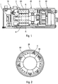
- FIG. 1 represents a sectional view of an electric compressor, presented in the document JP2005-291004 , in which the inverter housing 10 housing the inverter 1, the motor housing 20 housing the electric motor 2 and the compression housing 30 housing the compression mechanism 3 are connected to each other using fixing screws 4 of great length extending inside the motor housing 20.
- Fastening screws of great length have many disadvantages. They have a high manufacturing cost compared to screws of short length. In addition, during their manufacture, the fixing screws undergo a thermal curing step which generates residual surface tensions which are a function of the length of the fixing device and which cause a deflection or buckling of the fixing device. The longer a fastening screw, the more difficult it is to manufacture.
- the object of the present invention is to eliminate at least some of the disadvantages described above by modifying the compressor assembly. This advantageously makes it possible to assemble the compressor without resorting to fastening screws of great length.
- the invention relates to an electric compressor comprising a compression mechanism, an electric motor driving the compression mechanism, said electric motor having an axis of rotation, a power inverter of said electric motor, the inverter being mounted in an inverter housing, the compression mechanism being mounted in a compression housing, the electric motor being mounted in a housing extending longitudinally along the axis of rotation and having a first end connected to the inverter housing by a plurality of securing devices extending internally to the motor housing, wherein the motor housing has a second end, opposite the first end relative to the electric motor, connected to the compression casing by a plurality of securing devices separate from the fasteners.
- the assembly of the compressor by means of separate fixing and securing devices makes it possible to use devices of short length which have a low manufacturing cost and whose manufacturing process is easy.
- each attachment device has a longitudinal length less than the longitudinal length of the motor housing.
- Such a fixing device has a very small length which is advantageous.
- the plurality of securing devices extends internally to the compression casing.
- the compressor does not include any protruding part and thus has a small footprint.
- the second end of the motor housing is in the form of a transverse plane base, said base comprising a plurality of longitudinal positioning cavities of a fixing device.
- the fixing device is oriented longitudinally in the motor housing when positioned in its cavity.
- each attachment device comprises a body extending into a hole of the motor housing and a head abutting with the bottom of the longitudinal positioning cavity.
- Positioning cavities advantageously make it possible to limit the length of a fixing device, which is advantageous.
- the second end of the motor housing is in the form of a transverse plane base, said base comprising a plurality of tappings for receiving a securing device.
- the securing devices are received by the base while the fasteners are introduced into the base.
- the base advantageously ensures optimum mechanical fastening of the entire compressor by forming an attachment interface of the securing device and fixing.
- At least one tapping is formed in the base between two consecutive cavities so as to distribute the fasteners and the securing devices on the base.
- the fixing devices do not interfere with the securing devices.
- the second end of the motor housing is in the form of a transverse plane base, said base comprises at least one through-hole arranged to guide a refrigerant fluid to the compression means.
- the base advantageously provides a function for guiding the refrigerant fluid without interfering with the fastening and securing devices.
- the diameter of the fixing devices is less than the diameter of the securing devices.
- the number of fasteners is less than the number of fasteners.
- the inverter housing comprises a plurality of protrusions extending longitudinally in the motor housing, each projection having a tapped hole for receiving a fixing device.
- the protrusions advantageously make it possible to limit the length of the fixing devices, which is advantageous. This further avoids that the growths extend into the cavity of the Inverter box and encroach on the space available to install the inverter, in particular, a printed circuit board of the inverter.
- the protrusions are in contact with the inner periphery of the motor housing.
- the protrusions thus make it possible to center the inverter housing with respect to the motor housing.
- An electric compressor 7 according to the invention will be presented later for the circulation of a refrigerant inside an air conditioning circuit of a motor vehicle. It goes without saying that the electric compressor can be used for the compression of fluids of different kinds and that the electric compressor 7 can be mounted on any type of device both mobile and fixed.
- the electric compressor 7 comprises a compression mechanism 3, an electric motor 2 for driving the compression mechanism 3, said electric motor 2 having an axis of rotation X ( Figure 3 ) and an inverter 1 supplying said electric motor 2.
- the inverter 1 is mounted in an inverter housing 10 and the compression mechanism 3 is mounted in a compression box 30.
- the electric motor 2 is mounted in a housing motor housing 20 extending longitudinally along the axis of rotation X.
- the motor housing 20 is made of aluminum or aluminum alloy of hollow circular shape comprising a peripheral wall which delimits an internal volume terminated on one side by a first 20P end and the other by a second end 20S. These two ends 20P, 20S are open before mounting the other components of the compressor 7.
- the first end 20P is connected to the housing inverter 10 by a plurality of fixing devices 5 while the second end 20S, opposite the first end 20P with respect to the electric motor 2, is connected to the compression box 30 by a plurality of securing devices 6.
- the compression mechanism 3 is of the spiral compression type (Scroll in English) or of the type with vanes or the piston type, these examples being given for illustrative purposes without limiting the scope of the invention.
- the inverter transforms a stream of continuous form coming from the vehicle, in particular the battery, into a sinusoidal current of variable frequency supplying the electric motor 2.
- the motor 2 comprises an integrally circular periphery 2A stator mounted integrally in the motor housing 20 and a rotor 2B integral with the motor shaft 2 which rotates internally to the stator 2A.
- the stator 2A is fixedly placed outside the rotor 2B.
- the circular shape of the stator 2A is advantageous because it limits the magnetic losses and optimizes the efficiency of the motor 2.
- the terms "internal” and “external” are defined radially with respect to the axis X of the motor 2.
- an axial cylinder comprises an inner surface facing the axis and an outer surface opposite to its inner surface.
- the motor housing 20 comprises at its inner periphery a plurality of protuberances 23 in contact with the circular periphery of the stator 2A.
- the protuberances 23 are in the form of radial teeth, originating on the inner wall of the motor housing 20, the end of which is curvilinear so as to come in surface abutment on the circular periphery of the stator 2A.
- the protuberances 23 are distributed around the periphery of the motor housing 20 to fixably hold the motor 2 in its housing 20.
- the motor housing 20 comprises, at its inner periphery and between two consecutive protuberances 23, a plurality of holes 24 in which a fastening device 5 extends as shown in FIG. figure 4 .
- each fastener 5 extends internally to the motor housing 20 so as not to form a projecting portion outside the compressor 7.
- the compressor 7 is thus compact.
- a single fastening device 5 extends between two consecutive protuberances 23, but it goes without saying that a larger number of such devices could be used between two consecutive protuberances 23.
- the fastening device 5 thus entirely in the thickness of the motor housing 20 measured in line with a protuberance 23, that is to say, the radial thickness of the protuberance 23.
- the motor housing 20 also comprises at its inner periphery and between two consecutive protuberances 23 a plurality of recesses 22 whose function is to allow a circulation of the refrigerant in the direction of the X axis of the engine 2.
- the motor housing 20 comprises a coolant inlet 21 which opens between the electric motor 2 and the inverter housing 10 to introduce coolant F into the motor housing 20.
- This inlet port 21 takes the form of a pipe which extends radially outwardly of the motor housing 20 and a through hole formed in the wall of the motor housing 20 to the right of the tubing.
- the recesses 22 are able to channel the coolant F between the inner periphery of the motor housing 20 and the outer periphery of the stator 2A.
- This pipe has a passage section sufficient to allow the stator 2A to be cooled by circulating the refrigerant flow F without causing a pressure drop.
- the fastening devices 5 and the stator 2A of the motor 2 do not disturb the circulation of the refrigerant fluid F which guarantees an optimal flow of the fluid.
- annular space is advantageously formed between the periphery of the motor housing 20 and the periphery of the stator 2A in order to allow the formation of the holes 24 and the recesses 22 allowing, of on the one hand, the attachment of the compressor 7 and, on the other hand, the circulation of the refrigerant F.
- the second end 20S of the motor housing 20 is in the form of a transverse plane base 28 as shown in FIG. figure 8 .
- the base 28 comprises, in this example, a plurality of longitudinal cavities 25 for the positioning of the fixing devices 5, a plurality of through-holes 27 arranged to guide the flow of refrigerant fluid flowing through the recesses 22 to the compression box 30 and a plurality of tapped holes 26 formed longitudinally in the base 28 for receiving fastening devices 6 of the compression box 30 to the motor housing 20.
- each fastening device 5 comprises a longitudinal body 51 extending in the hole 24 and a head 52 in abutment with the bottom of the longitudinal positioning cavity 25.
- the fixing device 5 is, in this example, in the form of a fastening screw whose body 51 is threaded so as to be able to extend in the hole 24 and is screwed into a protrusion 11 of the inverter housing 10, as will be presented later.
- each fastener 5 extends into a hole 24 of the motor housing 20.
- Each longitudinal cavity 25 has a circular cross-section adapted to the diameter of the head 52 of the fastening device 5 as shown in FIG. figure 5 , the cross section of the hole 24 in which the body 51 extends being smaller than that of the longitudinal cavity 25.
- the axial length of the longitudinal cavity 25 advantageously allows the length of the body 51 of the fastening device 5 to be limited.
- the longitudinal length of the fixing device 5 is shorter than the longitudinal length of the motor housing 20 due to the presence of the longitudinal cavities 25 which extend internally to the volume of the motor housing 20 and allow the head 52 of the fixing device 5 to be in abutment with a wall located internally to the motor housing 20.
- the fasteners 5 undergo a thermal curing step which generates residual surface tensions which are a function of the length of the fastener. The shorter the fixing device, the easier it is to manufacture.
- the compression box 30 comprises a flat surface portion 30P, extending transversely to the axis of the motor X, which comes into contact with the flat surface of the base 28 so as to form a seal with respect to the refrigerant fluid F flowing in the motor housings 20 and compression 30. It is thus not necessary to provide individual seals for each fastener 5, the connection of the compression housing 30 to the motor housing 20 assuring sealing without additional means.
- the plurality of through-holes 27 of the base 28 advantageously allows the coolant F admitted via the inlet orifice 21 to be guided towards the compression casing 30.
- the recesses 22 of the motor casing 20 are able to channel the fluid refrigerant F from the inlet port 21 to a through-light 27 of the base 28 to form an internal pipe to the motor housing 20 whose passage section is sufficient to limit the pressure drop.
- the through-lights 27 extend longitudinally and have an axial section in the form of circular arcs formed on the base 28 at the same radial distance from the axis X of the motor 2 ( Figure 8 ). It goes without saying that the through-holes 27 could be in various forms in order to optimally calibrate the pressure of the coolant in the motor housing 20.
- the threads 26 of the base 28 extend longitudinally to receive fastening devices 6 of the compression box 30 to the motor housing 20.
- the securing devices 6 extend internally to the compressor in the compression housing 30.
- each securing device 6 comprises a longitudinal body 61 extending at least partially in the tapping 26 and a head 62 abutting against a transverse face of the compression casing 30.
- the securing device 6 is, in this example, under the form of a fastening screw whose body 61 is threaded so as to be screwed into the tapping 26 of the base 28.
- the threads 26 are distributed on the base 28 and are preferably interposed with the cavities of Positioning 25.
- at least one tapping 26 is formed in the base 28 between two consecutive cavities 25 so as to distribute the devices of FIG. 5 and the securing devices 6 on the base 28.
- the compressor 7 according to the invention is modular.
- the inverter boxes 10 and motor 20 are secured in a first step by the fastening devices 5.
- the housings of motor 20 and compression 30 are secured in a second step by the securing devices 6.
- Such an assembly is simple to implement and allows to benefit from a modular architecture in which each module can be designed, tested and validated independently.
- this advantageously makes it possible to resort to only fastening and securing devices of short length which have a low cost and a better service life.
- the base 28 of the motor housing 20 advantageously performs a link interface function by allowing, on the one hand, to introduce the fixing devices 5 and, on the other hand, to receive the securing devices 6.
- L base 28 also allows the circulation of the coolant F between the engine 20 and compression housings 30.
- the securing devices 6 must provide a greater maintenance than that provided by the fastening devices 5.
- the diameter of the fastening devices 5 may be smaller than the diameter of the fastening devices 6 and the number of fixing devices 5 may be less than the number of fastening devices 6.
- the inverter housing 10 comprises a plurality of substantially tubular protuberances 11 in contact with the inner periphery of the motor housing 20, extending longitudinally in the motor housing 20, each protrusion 11 having a hole 12
- the receiving holes 12 are blind and threaded in order to receive the end of the threaded body 51 of the fastening devices 5.
- the protuberances 11 of the inverter housing 10 advantageously serve a dual function. Firstly, they make it possible to precisely position the inverter housing 10 with respect to the motor housing 20 since they are in contact with the inner periphery of the motor housing 20. Secondly, they make it possible to fix the two housings 10, 20 by limiting the length of the fastening devices 5. Indeed, in the manner of the positioning cavities 25 which extend towards the center of the motor housing 20 from the second end 20S, the protuberances 11 extend towards the center of the motor housing 20 from the first end 20P in order to limit the longitudinal length of the fastening devices 5. The shorter the body 51, the easier it is to manufacture.
- the protrusions 11 extending longitudinally in the motor housing 20, the space available for the electronic components of the inverter 1 in the inverter housing 10 is important and allows the mounting of a card circuit board for the inverter 1 whose dimensions are substantially equal to those of the cross section of the inverter housing 10.
Landscapes
- Engineering & Computer Science (AREA)
- Mechanical Engineering (AREA)
- General Engineering & Computer Science (AREA)
- Power Engineering (AREA)
- Microelectronics & Electronic Packaging (AREA)
- Compressor (AREA)
- Applications Or Details Of Rotary Compressors (AREA)
Claims (9)
- Elektrischer Verdichter (7), der einen Verdichtungsmechanismus (3), einen elektrischen Motor (2) zum Antrieb des Verdichtungsmechanismus (3), wobei der elektrische Motor eine Drehachse (X) aufweist, einen Wechselrichter (1) zur Speisung des elektrischen Motors (2) umfasst, wobei der Wechselrichter (1) in einem Wechselrichtergehäuse (10) befestigt ist, wobei der Verdichtungsmechanismus (3) in einem Verdichtungsgehäuse (30) befestigt ist, wobei der elektrische Motor (2) in einem Gehäuse (20) befestigt ist, das sich in Längsrichtung entlang der Drehachse (X) erstreckt und ein erstes Ende (20P) aufweist, das mit dem Wechselrichtergehäuse (10) durch eine Mehrheit von Fixierungsvorrichtungen (5) verbunden ist, die sich im Inneren des Motorgehäuses (20) erstrecken, wobei das Motorgehäuse (20) ein zweites Ende (20S) entgegengesetzt zu dem ersten Ende (20P) im Verhältnis zu dem elektrischen Motors (2) aufweist, das mit dem Verdichtungsgehäuse (30) durch eine Mehrheit von Befestigungsvorrichtungen (6) verbunden ist, die sich von den Fixierungsvorrichtungen (5) unterscheiden, dadurch gekennzeichnet, dass das zweite Ende (20S) des Motorgehäuses (20) in Form einer planaren Querbasis (28) vorliegt, wobei die Basis (28) eine Mehrheit von Längshohlräumen (25) zur Positionierung der Fixierungsvorrichtungen (5) umfasst.
- Verdichter nach Anspruch 1, bei dem jede Fixierungsvorrichtung (5) eine in Längsrichtung verlaufende Länge aufweist, die weniger als die in Längsrichtung verlaufende Länge des Motorgehäuses (20) beträgt.
- Verdichter nach einem der Ansprüche 1-2, bei dem sich die Mehrheit von Befestigungsvorrichtungen (6) innerhalb des Verdichtungsgehäuses (30) erstrecken.
- Verdichter nach einem der Ansprüche 1-3,
wobei die Basis (28) eine Mehrheit von Innengewinden (26) zur Aufnahme einer Befestigungsvorrichtung (6) umfasst. - Verdichter nach einem der Ansprüche 1-4, bei dem mindestens ein Innengewinde (26) in der Basis (28) zwischen zwei aufeinanderfolgenden Hohlräumen (25) ausgebildet ist.
- Verdichter nach einem der Ansprüche 1-5, bei dem die Basis (28) mindestens ein Durchgangsloch (27) umfasst, das zum Leiten eines Kühlmittels (F) zu den Verdichtungsmitteln (3) angeordnet ist.
- Verdichter nach einem der Ansprüche 1-6, bei dem der Querschnitt der Fixierungsvorrichtungen (5) weniger als der Querschnitt der Befestigungsvorrichtungen (6) beträgt.
- Verdichter nach einem der Ansprüche 1-7, bei dem die Anzahl an Fixierungsvorrichtungen (5) unter der Anzahl an Befestigungsvorrichtungen (6) liegt.
- Verdichter nach einem der Ansprüche 1-8, bei dem das Wechselrichtergehäuse (10) eine Mehrheit von Vorsprüngen (11) umfasst, die sich in Längsrichtung in dem Motorgehäuse (20) erstrecken, wobei jeder Vorsprung (11) eine Gewindebohrung (12) zur Aufnahme einer Fixierungsvorrichtung (5) umfasst.
Applications Claiming Priority (2)
| Application Number | Priority Date | Filing Date | Title |
|---|---|---|---|
| FR1101545A FR2975448B1 (fr) | 2011-05-19 | 2011-05-19 | Compresseur electrique modulaire avec dispositif de fixation integre |
| PCT/EP2012/001630 WO2012156011A1 (fr) | 2011-05-19 | 2012-04-16 | Compresseur electrique modulaire avec dispositif de fixation integre |
Publications (2)
| Publication Number | Publication Date |
|---|---|
| EP2710264A1 EP2710264A1 (de) | 2014-03-26 |
| EP2710264B1 true EP2710264B1 (de) | 2017-08-23 |
Family
ID=46017773
Family Applications (1)
| Application Number | Title | Priority Date | Filing Date |
|---|---|---|---|
| EP12717187.4A Not-in-force EP2710264B1 (de) | 2011-05-19 | 2012-04-16 | Modularer elektrischer verdichter mit eingebauter sicherungsvorrichtung |
Country Status (5)
| Country | Link |
|---|---|
| US (1) | US10221840B2 (de) |
| EP (1) | EP2710264B1 (de) |
| JP (1) | JP6026516B2 (de) |
| FR (1) | FR2975448B1 (de) |
| WO (1) | WO2012156011A1 (de) |
Families Citing this family (10)
| Publication number | Priority date | Publication date | Assignee | Title |
|---|---|---|---|---|
| JP6178564B2 (ja) * | 2012-12-04 | 2017-08-09 | カルソニックカンセイ株式会社 | 電動コンプレッサ |
| FR3010461B1 (fr) * | 2013-09-10 | 2016-05-13 | Valeo Japan Co Ltd | Plaque de reprise d'effort d'un compresseur et ledit compresseur |
| FR3023328B1 (fr) * | 2014-07-07 | 2019-03-22 | Valeo Japan Co., Ltd. | Plaque d'un compresseur electrique et compresseur electrique comprenant une telle plaque |
| EP3167190B1 (de) | 2014-07-08 | 2021-07-07 | Flow Control LLC. | Verfahren zur befestigung von pumpen an elektrischen motoren |
| KR102202419B1 (ko) * | 2015-04-17 | 2021-01-13 | 한온시스템 주식회사 | 전동 압축기 |
| JPWO2016199884A1 (ja) * | 2015-06-12 | 2018-03-29 | 株式会社ヴァレオジャパン | 電動圧縮機 |
| DE102016204756B4 (de) * | 2015-12-23 | 2024-01-11 | OET GmbH | Elektrischer Kältemittelantrieb |
| US11228223B2 (en) * | 2018-05-21 | 2022-01-18 | Steering Solutions Ip Holding Corporation | Electric power steering sealing valve system, a valve assembly arranged in the end cap |
| DE102020203260A1 (de) | 2019-03-28 | 2020-10-01 | Kabushiki Kaisha Toyota Jidoshokki | Elektrischer kompressor |
| US12292057B2 (en) | 2020-04-15 | 2025-05-06 | Ihi Corporation | Fluid machine |
Family Cites Families (9)
| Publication number | Priority date | Publication date | Assignee | Title |
|---|---|---|---|---|
| US5868175A (en) * | 1996-06-28 | 1999-02-09 | Franklin Electric Co., Inc. | Apparatus for recovery of fuel vapor |
| JP2002070743A (ja) * | 2000-08-29 | 2002-03-08 | Sanden Corp | 冷媒圧縮用電動式圧縮機 |
| JP4667651B2 (ja) * | 2001-06-08 | 2011-04-13 | パナソニック株式会社 | 電動機内蔵の圧縮機と、これを搭載した移動車 |
| JP4045125B2 (ja) | 2002-05-24 | 2008-02-13 | サンデン株式会社 | 電動圧縮機 |
| US20060239833A1 (en) * | 2003-04-23 | 2006-10-26 | Taeyoung Park | Motor driven compressor |
| JP2005291004A (ja) | 2004-03-31 | 2005-10-20 | Sanden Corp | 電動圧縮機 |
| JP2009150234A (ja) * | 2007-12-18 | 2009-07-09 | Toyota Industries Corp | 電動圧縮機 |
| JP2010285980A (ja) | 2009-05-13 | 2010-12-24 | Sanden Corp | インバータ一体型電動圧縮機 |
| JP5192440B2 (ja) * | 2009-05-15 | 2013-05-08 | 株式会社神戸製鋼所 | モータ及びこれを備えた圧縮機 |
-
2011
- 2011-05-19 FR FR1101545A patent/FR2975448B1/fr not_active Expired - Fee Related
-
2012
- 2012-04-16 EP EP12717187.4A patent/EP2710264B1/de not_active Not-in-force
- 2012-04-16 WO PCT/EP2012/001630 patent/WO2012156011A1/fr not_active Ceased
- 2012-04-16 JP JP2014510678A patent/JP6026516B2/ja active Active
- 2012-04-16 US US14/118,339 patent/US10221840B2/en active Active
Non-Patent Citations (1)
| Title |
|---|
| None * |
Also Published As
| Publication number | Publication date |
|---|---|
| WO2012156011A1 (fr) | 2012-11-22 |
| FR2975448B1 (fr) | 2017-07-14 |
| EP2710264A1 (de) | 2014-03-26 |
| JP6026516B2 (ja) | 2016-11-16 |
| JP2014513772A (ja) | 2014-06-05 |
| US10221840B2 (en) | 2019-03-05 |
| CN103703248A (zh) | 2014-04-02 |
| FR2975448A1 (fr) | 2012-11-23 |
| US20140205478A1 (en) | 2014-07-24 |
Similar Documents
| Publication | Publication Date | Title |
|---|---|---|
| WO2012156011A1 (fr) | Compresseur electrique modulaire avec dispositif de fixation integre | |
| EP3857685B1 (de) | Elektrischer aktuator | |
| EP1247012B1 (de) | Turbolader mit verschiebbaren leitschaufeln, hitzeschild und einer abnehmbaren, axialen betätigungsvorrichtung | |
| EP2710265B1 (de) | Modularer elektrischer kompressor mit einer anordnungsvorrichtung | |
| FR2991009A1 (fr) | Boitier de compresseur electrique comprenant un dispositif de dissipation, et compresseur comportant un tel boitier | |
| FR2968753A1 (fr) | Echangeur de chaleur, notamment pour vehicule automobile | |
| CA2494943C (fr) | Diffuseur pour turboreacteur | |
| WO2021255383A1 (fr) | Turbomachine d'aeronef a cycle recupere | |
| WO2022029386A1 (fr) | Compresseur centrifuge multi-étages | |
| EP4005072B1 (de) | Elektrische maschine und herstellungsverfahren | |
| EP4069945A1 (de) | Starre stange zur elektrischen verbindung einer maschine in einem flugtriebwerk | |
| WO2021111061A1 (fr) | Raccordement électrique d'une machine électrique dans une turbomachine d'aéronef | |
| EP1956297B1 (de) | Gasturbinenverbrennungskammer | |
| EP3811506B1 (de) | Supraleitende rotierende maschine | |
| FR2928426A1 (fr) | Motoventilateur | |
| EP3320601B1 (de) | Drehende elektromaschine mit einem zentrierelement | |
| FR2887924A1 (fr) | Dispositif de guidage d'un flux d'air entre un compresseur et une chambre de combustion dans une turbomachine | |
| FR3074982A1 (fr) | Moteur synchrone, notamment pour compresseur electrique | |
| FR2865079A1 (fr) | Machine electrique tournante pour vehicule | |
| WO2020193297A1 (fr) | Rotor de machine electrique avec moyen de ventilation axialo-centrifuge | |
| FR3010461A1 (fr) | Plaque de reprise d'effort d'un compresseur et ledit compresseur | |
| FR2924871A1 (fr) | Bague de support d'un moteur electrique muni d'un deflecteur | |
| FR3055755B1 (fr) | Machine electrique tournante comprenant un ensemble electronique demontable | |
| WO2026087458A1 (fr) | Carter de machine electrique | |
| FR3057464A1 (fr) | Appareil d'assistance respiratoire a systeme de refroidissement integre |
Legal Events
| Date | Code | Title | Description |
|---|---|---|---|
| PUAI | Public reference made under article 153(3) epc to a published international application that has entered the european phase |
Free format text: ORIGINAL CODE: 0009012 |
|
| 17P | Request for examination filed |
Effective date: 20131112 |
|
| AK | Designated contracting states |
Kind code of ref document: A1 Designated state(s): AL AT BE BG CH CY CZ DE DK EE ES FI FR GB GR HR HU IE IS IT LI LT LU LV MC MK MT NL NO PL PT RO RS SE SI SK SM TR |
|
| RIN1 | Information on inventor provided before grant (corrected) |
Inventor name: OKAKURA, HIROAKI Inventor name: DEGUCHI, HIRONOBU Inventor name: BELLET, AUGUSTIN Inventor name: GUITARI, IMED |
|
| DAX | Request for extension of the european patent (deleted) | ||
| RIN1 | Information on inventor provided before grant (corrected) |
Inventor name: BELLET, AUGUSTIN Inventor name: DEGUCHI, HIRONOBU Inventor name: OKAKURA, HIROAKI Inventor name: GUITARI, IMED |
|
| GRAJ | Information related to disapproval of communication of intention to grant by the applicant or resumption of examination proceedings by the epo deleted |
Free format text: ORIGINAL CODE: EPIDOSDIGR1 |
|
| GRAP | Despatch of communication of intention to grant a patent |
Free format text: ORIGINAL CODE: EPIDOSNIGR1 |
|
| GRAP | Despatch of communication of intention to grant a patent |
Free format text: ORIGINAL CODE: EPIDOSNIGR1 |
|
| INTG | Intention to grant announced |
Effective date: 20170310 |
|
| RIN1 | Information on inventor provided before grant (corrected) |
Inventor name: OKAKURA, HIROAKI Inventor name: DEGUCHI, HIRONOBU Inventor name: BELLET, AUGUSTIN Inventor name: GUITARI, IMED |
|
| GRAS | Grant fee paid |
Free format text: ORIGINAL CODE: EPIDOSNIGR3 |
|
| GRAA | (expected) grant |
Free format text: ORIGINAL CODE: 0009210 |
|
| AK | Designated contracting states |
Kind code of ref document: B1 Designated state(s): AL AT BE BG CH CY CZ DE DK EE ES FI FR GB GR HR HU IE IS IT LI LT LU LV MC MK MT NL NO PL PT RO RS SE SI SK SM TR |
|
| REG | Reference to a national code |
Ref country code: GB Ref legal event code: FG4D Free format text: NOT ENGLISH |
|
| REG | Reference to a national code |
Ref country code: CH Ref legal event code: EP |
|
| REG | Reference to a national code |
Ref country code: AT Ref legal event code: REF Ref document number: 921645 Country of ref document: AT Kind code of ref document: T Effective date: 20170915 |
|
| REG | Reference to a national code |
Ref country code: IE Ref legal event code: FG4D Free format text: LANGUAGE OF EP DOCUMENT: FRENCH |
|
| REG | Reference to a national code |
Ref country code: DE Ref legal event code: R096 Ref document number: 602012036270 Country of ref document: DE |
|
| REG | Reference to a national code |
Ref country code: NL Ref legal event code: MP Effective date: 20170823 |
|
| REG | Reference to a national code |
Ref country code: LT Ref legal event code: MG4D |
|
| REG | Reference to a national code |
Ref country code: AT Ref legal event code: MK05 Ref document number: 921645 Country of ref document: AT Kind code of ref document: T Effective date: 20170823 |
|
| PG25 | Lapsed in a contracting state [announced via postgrant information from national office to epo] |
Ref country code: AT Free format text: LAPSE BECAUSE OF FAILURE TO SUBMIT A TRANSLATION OF THE DESCRIPTION OR TO PAY THE FEE WITHIN THE PRESCRIBED TIME-LIMIT Effective date: 20170823 Ref country code: SE Free format text: LAPSE BECAUSE OF FAILURE TO SUBMIT A TRANSLATION OF THE DESCRIPTION OR TO PAY THE FEE WITHIN THE PRESCRIBED TIME-LIMIT Effective date: 20170823 Ref country code: NO Free format text: LAPSE BECAUSE OF FAILURE TO SUBMIT A TRANSLATION OF THE DESCRIPTION OR TO PAY THE FEE WITHIN THE PRESCRIBED TIME-LIMIT Effective date: 20171123 Ref country code: FI Free format text: LAPSE BECAUSE OF FAILURE TO SUBMIT A TRANSLATION OF THE DESCRIPTION OR TO PAY THE FEE WITHIN THE PRESCRIBED TIME-LIMIT Effective date: 20170823 Ref country code: LT Free format text: LAPSE BECAUSE OF FAILURE TO SUBMIT A TRANSLATION OF THE DESCRIPTION OR TO PAY THE FEE WITHIN THE PRESCRIBED TIME-LIMIT Effective date: 20170823 Ref country code: HR Free format text: LAPSE BECAUSE OF FAILURE TO SUBMIT A TRANSLATION OF THE DESCRIPTION OR TO PAY THE FEE WITHIN THE PRESCRIBED TIME-LIMIT Effective date: 20170823 Ref country code: NL Free format text: LAPSE BECAUSE OF FAILURE TO SUBMIT A TRANSLATION OF THE DESCRIPTION OR TO PAY THE FEE WITHIN THE PRESCRIBED TIME-LIMIT Effective date: 20170823 |
|
| PG25 | Lapsed in a contracting state [announced via postgrant information from national office to epo] |
Ref country code: BG Free format text: LAPSE BECAUSE OF FAILURE TO SUBMIT A TRANSLATION OF THE DESCRIPTION OR TO PAY THE FEE WITHIN THE PRESCRIBED TIME-LIMIT Effective date: 20171123 Ref country code: LV Free format text: LAPSE BECAUSE OF FAILURE TO SUBMIT A TRANSLATION OF THE DESCRIPTION OR TO PAY THE FEE WITHIN THE PRESCRIBED TIME-LIMIT Effective date: 20170823 Ref country code: ES Free format text: LAPSE BECAUSE OF FAILURE TO SUBMIT A TRANSLATION OF THE DESCRIPTION OR TO PAY THE FEE WITHIN THE PRESCRIBED TIME-LIMIT Effective date: 20170823 Ref country code: GR Free format text: LAPSE BECAUSE OF FAILURE TO SUBMIT A TRANSLATION OF THE DESCRIPTION OR TO PAY THE FEE WITHIN THE PRESCRIBED TIME-LIMIT Effective date: 20171124 Ref country code: RS Free format text: LAPSE BECAUSE OF FAILURE TO SUBMIT A TRANSLATION OF THE DESCRIPTION OR TO PAY THE FEE WITHIN THE PRESCRIBED TIME-LIMIT Effective date: 20170823 Ref country code: PL Free format text: LAPSE BECAUSE OF FAILURE TO SUBMIT A TRANSLATION OF THE DESCRIPTION OR TO PAY THE FEE WITHIN THE PRESCRIBED TIME-LIMIT Effective date: 20170823 Ref country code: IS Free format text: LAPSE BECAUSE OF FAILURE TO SUBMIT A TRANSLATION OF THE DESCRIPTION OR TO PAY THE FEE WITHIN THE PRESCRIBED TIME-LIMIT Effective date: 20171223 |
|
| REG | Reference to a national code |
Ref country code: FR Ref legal event code: PLFP Year of fee payment: 7 |
|
| PG25 | Lapsed in a contracting state [announced via postgrant information from national office to epo] |
Ref country code: RO Free format text: LAPSE BECAUSE OF FAILURE TO SUBMIT A TRANSLATION OF THE DESCRIPTION OR TO PAY THE FEE WITHIN THE PRESCRIBED TIME-LIMIT Effective date: 20170823 Ref country code: CZ Free format text: LAPSE BECAUSE OF FAILURE TO SUBMIT A TRANSLATION OF THE DESCRIPTION OR TO PAY THE FEE WITHIN THE PRESCRIBED TIME-LIMIT Effective date: 20170823 Ref country code: DK Free format text: LAPSE BECAUSE OF FAILURE TO SUBMIT A TRANSLATION OF THE DESCRIPTION OR TO PAY THE FEE WITHIN THE PRESCRIBED TIME-LIMIT Effective date: 20170823 |
|
| REG | Reference to a national code |
Ref country code: DE Ref legal event code: R097 Ref document number: 602012036270 Country of ref document: DE |
|
| PG25 | Lapsed in a contracting state [announced via postgrant information from national office to epo] |
Ref country code: SK Free format text: LAPSE BECAUSE OF FAILURE TO SUBMIT A TRANSLATION OF THE DESCRIPTION OR TO PAY THE FEE WITHIN THE PRESCRIBED TIME-LIMIT Effective date: 20170823 Ref country code: IT Free format text: LAPSE BECAUSE OF FAILURE TO SUBMIT A TRANSLATION OF THE DESCRIPTION OR TO PAY THE FEE WITHIN THE PRESCRIBED TIME-LIMIT Effective date: 20170823 Ref country code: SM Free format text: LAPSE BECAUSE OF FAILURE TO SUBMIT A TRANSLATION OF THE DESCRIPTION OR TO PAY THE FEE WITHIN THE PRESCRIBED TIME-LIMIT Effective date: 20170823 Ref country code: EE Free format text: LAPSE BECAUSE OF FAILURE TO SUBMIT A TRANSLATION OF THE DESCRIPTION OR TO PAY THE FEE WITHIN THE PRESCRIBED TIME-LIMIT Effective date: 20170823 |
|
| PLBE | No opposition filed within time limit |
Free format text: ORIGINAL CODE: 0009261 |
|
| STAA | Information on the status of an ep patent application or granted ep patent |
Free format text: STATUS: NO OPPOSITION FILED WITHIN TIME LIMIT |
|
| 26N | No opposition filed |
Effective date: 20180524 |
|
| PG25 | Lapsed in a contracting state [announced via postgrant information from national office to epo] |
Ref country code: SI Free format text: LAPSE BECAUSE OF FAILURE TO SUBMIT A TRANSLATION OF THE DESCRIPTION OR TO PAY THE FEE WITHIN THE PRESCRIBED TIME-LIMIT Effective date: 20170823 |
|
| PG25 | Lapsed in a contracting state [announced via postgrant information from national office to epo] |
Ref country code: MT Free format text: LAPSE BECAUSE OF FAILURE TO SUBMIT A TRANSLATION OF THE DESCRIPTION OR TO PAY THE FEE WITHIN THE PRESCRIBED TIME-LIMIT Effective date: 20170823 |
|
| PG25 | Lapsed in a contracting state [announced via postgrant information from national office to epo] |
Ref country code: MC Free format text: LAPSE BECAUSE OF FAILURE TO SUBMIT A TRANSLATION OF THE DESCRIPTION OR TO PAY THE FEE WITHIN THE PRESCRIBED TIME-LIMIT Effective date: 20170823 |
|
| REG | Reference to a national code |
Ref country code: CH Ref legal event code: PL |
|
| REG | Reference to a national code |
Ref country code: BE Ref legal event code: MM Effective date: 20180430 |
|
| REG | Reference to a national code |
Ref country code: IE Ref legal event code: MM4A |
|
| PG25 | Lapsed in a contracting state [announced via postgrant information from national office to epo] |
Ref country code: LU Free format text: LAPSE BECAUSE OF NON-PAYMENT OF DUE FEES Effective date: 20180416 |
|
| PG25 | Lapsed in a contracting state [announced via postgrant information from national office to epo] |
Ref country code: CH Free format text: LAPSE BECAUSE OF NON-PAYMENT OF DUE FEES Effective date: 20180430 Ref country code: LI Free format text: LAPSE BECAUSE OF NON-PAYMENT OF DUE FEES Effective date: 20180430 Ref country code: BE Free format text: LAPSE BECAUSE OF NON-PAYMENT OF DUE FEES Effective date: 20180430 |
|
| PG25 | Lapsed in a contracting state [announced via postgrant information from national office to epo] |
Ref country code: IE Free format text: LAPSE BECAUSE OF NON-PAYMENT OF DUE FEES Effective date: 20180416 |
|
| PG25 | Lapsed in a contracting state [announced via postgrant information from national office to epo] |
Ref country code: TR Free format text: LAPSE BECAUSE OF FAILURE TO SUBMIT A TRANSLATION OF THE DESCRIPTION OR TO PAY THE FEE WITHIN THE PRESCRIBED TIME-LIMIT Effective date: 20170823 |
|
| PG25 | Lapsed in a contracting state [announced via postgrant information from national office to epo] |
Ref country code: HU Free format text: LAPSE BECAUSE OF FAILURE TO SUBMIT A TRANSLATION OF THE DESCRIPTION OR TO PAY THE FEE WITHIN THE PRESCRIBED TIME-LIMIT; INVALID AB INITIO Effective date: 20120416 Ref country code: PT Free format text: LAPSE BECAUSE OF FAILURE TO SUBMIT A TRANSLATION OF THE DESCRIPTION OR TO PAY THE FEE WITHIN THE PRESCRIBED TIME-LIMIT Effective date: 20170823 |
|
| PG25 | Lapsed in a contracting state [announced via postgrant information from national office to epo] |
Ref country code: MK Free format text: LAPSE BECAUSE OF NON-PAYMENT OF DUE FEES Effective date: 20170823 Ref country code: CY Free format text: LAPSE BECAUSE OF FAILURE TO SUBMIT A TRANSLATION OF THE DESCRIPTION OR TO PAY THE FEE WITHIN THE PRESCRIBED TIME-LIMIT Effective date: 20170823 |
|
| PG25 | Lapsed in a contracting state [announced via postgrant information from national office to epo] |
Ref country code: AL Free format text: LAPSE BECAUSE OF FAILURE TO SUBMIT A TRANSLATION OF THE DESCRIPTION OR TO PAY THE FEE WITHIN THE PRESCRIBED TIME-LIMIT Effective date: 20170823 |
|
| PGFP | Annual fee paid to national office [announced via postgrant information from national office to epo] |
Ref country code: DE Payment date: 20210408 Year of fee payment: 10 |
|
| PGFP | Annual fee paid to national office [announced via postgrant information from national office to epo] |
Ref country code: GB Payment date: 20210415 Year of fee payment: 10 |
|
| REG | Reference to a national code |
Ref country code: DE Ref legal event code: R119 Ref document number: 602012036270 Country of ref document: DE |
|
| GBPC | Gb: european patent ceased through non-payment of renewal fee |
Effective date: 20220416 |
|
| PG25 | Lapsed in a contracting state [announced via postgrant information from national office to epo] |
Ref country code: GB Free format text: LAPSE BECAUSE OF NON-PAYMENT OF DUE FEES Effective date: 20220416 Ref country code: DE Free format text: LAPSE BECAUSE OF NON-PAYMENT OF DUE FEES Effective date: 20221103 |
|
| PGFP | Annual fee paid to national office [announced via postgrant information from national office to epo] |
Ref country code: FR Payment date: 20230425 Year of fee payment: 12 |
|
| P01 | Opt-out of the competence of the unified patent court (upc) registered |
Effective date: 20230629 |
|
| PG25 | Lapsed in a contracting state [announced via postgrant information from national office to epo] |
Ref country code: FR Free format text: LAPSE BECAUSE OF NON-PAYMENT OF DUE FEES Effective date: 20240430 |
|
| PG25 | Lapsed in a contracting state [announced via postgrant information from national office to epo] |
Ref country code: FR Free format text: LAPSE BECAUSE OF NON-PAYMENT OF DUE FEES Effective date: 20240430 |