EP4005072B1 - Elektrische maschine und herstellungsverfahren - Google Patents
Elektrische maschine und herstellungsverfahren Download PDFInfo
- Publication number
- EP4005072B1 EP4005072B1 EP20733458.2A EP20733458A EP4005072B1 EP 4005072 B1 EP4005072 B1 EP 4005072B1 EP 20733458 A EP20733458 A EP 20733458A EP 4005072 B1 EP4005072 B1 EP 4005072B1
- Authority
- EP
- European Patent Office
- Prior art keywords
- stator
- casing
- mass
- rotor
- thermal conductivity
- Prior art date
- Legal status (The legal status is an assumption and is not a legal conclusion. Google has not performed a legal analysis and makes no representation as to the accuracy of the status listed.)
- Active
Links
Images
Classifications
-
- H—ELECTRICITY
- H02—GENERATION; CONVERSION OR DISTRIBUTION OF ELECTRIC POWER
- H02K—DYNAMO-ELECTRIC MACHINES
- H02K5/00—Casings; Enclosures; Supports
- H02K5/04—Casings or enclosures characterised by the shape, form or construction thereof
- H02K5/20—Casings or enclosures characterised by the shape, form or construction thereof with channels or ducts for flow of cooling medium
- H02K5/203—Casings or enclosures characterised by the shape, form or construction thereof with channels or ducts for flow of cooling medium specially adapted for liquids, e.g. cooling jackets
-
- H—ELECTRICITY
- H02—GENERATION; CONVERSION OR DISTRIBUTION OF ELECTRIC POWER
- H02K—DYNAMO-ELECTRIC MACHINES
- H02K1/00—Details of the magnetic circuit
- H02K1/06—Details of the magnetic circuit characterised by the shape, form or construction
- H02K1/12—Stationary parts of the magnetic circuit
- H02K1/20—Stationary parts of the magnetic circuit with channels or ducts for flow of cooling medium
-
- H—ELECTRICITY
- H02—GENERATION; CONVERSION OR DISTRIBUTION OF ELECTRIC POWER
- H02K—DYNAMO-ELECTRIC MACHINES
- H02K15/00—Processes or apparatus specially adapted for manufacturing, assembling, maintaining or repairing of dynamo-electric machines
-
- H—ELECTRICITY
- H02—GENERATION; CONVERSION OR DISTRIBUTION OF ELECTRIC POWER
- H02K—DYNAMO-ELECTRIC MACHINES
- H02K15/00—Processes or apparatus specially adapted for manufacturing, assembling, maintaining or repairing of dynamo-electric machines
- H02K15/14—Casings; Enclosures; Supports
-
- H—ELECTRICITY
- H02—GENERATION; CONVERSION OR DISTRIBUTION OF ELECTRIC POWER
- H02K—DYNAMO-ELECTRIC MACHINES
- H02K15/00—Processes or apparatus specially adapted for manufacturing, assembling, maintaining or repairing of dynamo-electric machines
- H02K15/50—Disassembling, repairing or modifying dynamo-electric machines
-
- H—ELECTRICITY
- H02—GENERATION; CONVERSION OR DISTRIBUTION OF ELECTRIC POWER
- H02K—DYNAMO-ELECTRIC MACHINES
- H02K5/00—Casings; Enclosures; Supports
- H02K5/02—Casings or enclosures characterised by the material thereof
-
- H—ELECTRICITY
- H02—GENERATION; CONVERSION OR DISTRIBUTION OF ELECTRIC POWER
- H02K—DYNAMO-ELECTRIC MACHINES
- H02K5/00—Casings; Enclosures; Supports
- H02K5/04—Casings or enclosures characterised by the shape, form or construction thereof
-
- H—ELECTRICITY
- H02—GENERATION; CONVERSION OR DISTRIBUTION OF ELECTRIC POWER
- H02K—DYNAMO-ELECTRIC MACHINES
- H02K5/00—Casings; Enclosures; Supports
- H02K5/04—Casings or enclosures characterised by the shape, form or construction thereof
- H02K5/10—Casings or enclosures characterised by the shape, form or construction thereof with arrangements for protection from ingress, e.g. water or fingers
-
- H—ELECTRICITY
- H02—GENERATION; CONVERSION OR DISTRIBUTION OF ELECTRIC POWER
- H02K—DYNAMO-ELECTRIC MACHINES
- H02K9/00—Arrangements for cooling or ventilating
- H02K9/14—Arrangements for cooling or ventilating wherein gaseous cooling medium circulates between the machine casing and a surrounding mantle
- H02K9/16—Arrangements for cooling or ventilating wherein gaseous cooling medium circulates between the machine casing and a surrounding mantle wherein the cooling medium circulates through ducts or tubes within the casing
-
- H—ELECTRICITY
- H02—GENERATION; CONVERSION OR DISTRIBUTION OF ELECTRIC POWER
- H02K—DYNAMO-ELECTRIC MACHINES
- H02K9/00—Arrangements for cooling or ventilating
- H02K9/19—Arrangements for cooling or ventilating for machines with closed casing and closed-circuit cooling using a liquid cooling medium, e.g. oil
-
- H—ELECTRICITY
- H02—GENERATION; CONVERSION OR DISTRIBUTION OF ELECTRIC POWER
- H02K—DYNAMO-ELECTRIC MACHINES
- H02K9/00—Arrangements for cooling or ventilating
- H02K9/19—Arrangements for cooling or ventilating for machines with closed casing and closed-circuit cooling using a liquid cooling medium, e.g. oil
- H02K9/193—Arrangements for cooling or ventilating for machines with closed casing and closed-circuit cooling using a liquid cooling medium, e.g. oil with provision for replenishing the cooling medium; with means for preventing leakage of the cooling medium
-
- H—ELECTRICITY
- H02—GENERATION; CONVERSION OR DISTRIBUTION OF ELECTRIC POWER
- H02K—DYNAMO-ELECTRIC MACHINES
- H02K2205/00—Specific aspects not provided for in the other groups of this subclass relating to casings, enclosures, supports
- H02K2205/09—Machines characterised by drain passages or by venting, breathing or pressure compensating means
Definitions
- the invention relates to an electric machine and its manufacturing method.
- the invention relates more particularly to an electric machine, in particular an electric motor for driving at least one compressor or circulator, comprising a stator and a rotor arranged in a casing, the machine comprising a cooling device arranged around the stator and comprising a circuit for circulating a cooling fluid.
- Known cooling devices provide a circuit for circulating a cooling fluid housed in a housing that is sealed or hermetic with respect to the external environment.
- the sealing of this circuit with respect to the rest of the internal volume of the housing of the machine is achieved by welds and/or seals.
- coolant leaks into the rest of the machine can have significant consequences.
- the machine is a drive motor for a compressor housed in the sealed casing of the machine
- the leaking coolant can mix with the compressed cycle gas. This pollution can damage the installation using this cycle gas.
- An aim of the present invention is to overcome all or part of the drawbacks of the prior art noted above.
- the invention also relates to a method of manufacturing an electric machine, in particular a motor, in accordance with one of the following: any of the above or below features, the machine comprising a stator and a rotor arranged in a housing and a cooling device comprising a cooling fluid circulation pipe comprising a portion embedded in a mass of material with high thermal conductivity such as metal or a metal alloy, wherein the cooling device is pre-assembled to the stator before its introduction into the housing.
- the invention may also relate to any alternative device or method comprising any combination of the above or below features within the scope of the claims.
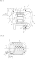
- the electric machine 1 (notably an electric motor) illustrated in the figure 1 comprises a stator 2 and a rotor 3 arranged in a casing 10.
- the casing 10 delimits a preferably hermetic and sealed volume housing the stator 2, the rotor 3 and the cooling device.
- the stator 2 is arranged around the rotor 3, around a longitudinal axis 11.
- the rotor 3 drives for example a rotation shaft on which is mounted a compressor 9 or circulator. That is to say that the machine 1 can be a motor-compressor in particular. Of course the machine can also be a motor-turbocharger having a turbine mounted on the other end of the shaft and/or a motor driving several compressors for example a motor-compressor two-stage (having a compressor wheel on each side of the rotating shaft).
- At least part of the casing 10 may have an axisymmetric shape (symmetrical around the axis 11) and for example cylindrical or tubular and arranged around the stator 2 (around the longitudinal axis 11).
- the casing 10 may be composed of metal part(s) assembled in a sealed manner by means of seals and fixing pins in particular.
- the machine 1 comprises a cooling device arranged around the stator 2.
- This device conventionally comprises a cooling fluid circuit, in particular a heat transfer fluid.
- a heat transfer fluid is generally a liquid which is intended to exchange heat directly or indirectly with a part of the machine and in particular the stator 2.
- the cooling fluid may be water or any other liquid or gas or two-phase mixture capable of transporting heat.
- this cooling device comprises a pipe 5 for circulating the cooling fluid comprising a portion embedded in a mass 4 of material with high thermal conductivity such as metal or a metal alloy.
- This portion of the circulation pipe 5 embedded in the mass 4 of material with high thermal conductivity may in particular be helical and/or describe zigzags. That is to say that the pipe forms multiple passages (in a loop, zigzag or other) around and/or along the stator 2.
- pipe 5 is bent (preferably without welding).
- this pipe 5 for example makes a helical round trip in the direction of the longitudinal axis 11. This makes it possible to obtain a uniform temperature of the stator 2.
- the inlet 6 and outlet 7 of the fluid are located on the same longitudinal side of the stator 2.
- the pipe 5 is formed of two groups of propellers which progress respectively in the longitudinal direction 11 in two opposite directions (respectively forward and reverse). These two groups of propellers can be nested or alternate. That is to say that, between two propellers or turns which cause the fluid to pass in a first longitudinal direction, there is located a propeller or turn which causes the fluid to circulate in the opposite longitudinal direction.
- the pipe 5 can be curved longitudinally. That is to say, the pipe 5 can comprise portions (in particular rectilinear) of opposite directions which extend in a direction parallel to the longitudinal axis 11. That is to say, the pipe 5 forms rectilinear back-and-forths in directions parallel to the longitudinal direction 11. These longitudinal portions can correspond to generatrices of a cylinder whose central axis is the longitudinal axis 11. The pipe is then curved at the junction between two adjacent longitudinal portions. Other orientations can be provided.
- any other geometry of the pipe 5 can be envisaged all around or only around a part of the stator.
- a return portion of the pipe 5 can be made directly through the mass 4 of material with high thermal conductivity via a tube, in particular a straight tube.
- the assembly comprising the mass 4 of material with high thermal conductivity and the pipe forms a tubular block which extends in a longitudinal direction and the two ends 6, 7 of which are located at the same longitudinal end of the mass 4.
- High thermal conductivity means a thermal conductivity comparable to that of metal or a metal alloy.
- mass 4 of material with high thermal conductivity is composed of aluminum or an aluminum alloy.
- This mass 4 of material with high thermal conductivity is overmolded around the fluid circulation pipe 5.
- the coolant circulation pipe 5 may be made of a metallic material or a metallic alloy, in particular a stainless steel alloy.
- the mass 4 of material with high thermal conductivity has for example a tubular and/or cylindrical shape and the stator 2, for example cylindrical, is housed in and in contact with the internal surface of said mass 4. That is to say that the mass 4 can have a cylindrical shape which is crossed by the tube formed by the circulation pipe 5, that is to say that the volume of the mass of metal does not fill the entire cylinder.
- the outer surface of the stator 2 is cylindrical and is threaded into a cylindrical tube formed by the mass 4 of material with high thermal conductivity in a longitudinal direction which is parallel to the axis of rotation of the rotor 3.
- the stator 2 can be mounted in the mass 4 of material with high thermal conductivity by shrink fitting. This provides good thermal conduction between these two elements for the purpose of efficient cooling of the stator 2.
- an intermediate element can be interposed in order to reduce the contact resistance (glue or thermal grease for example).
- This mass 4 of material with high thermal conductivity can have a volume equal to or greater (for example 1.5 to 3 times greater) than the volume of the portion of pipe that it houses.
- This mass 4 can thus have a thermal inertia promoting efficient cooling.
- the cooling device and the stator 2 can be preassembled and then the rotor can be mounted in the stator and the assembly can be mounted in the housing 10 of the machine 1.
- the casing 10 comprises an access cover 8 providing access, in the open position, to the stator 2, the rotor 3 and the cooling device.
- this access is oriented in a longitudinal direction 11 parallel to the axis of rotation of the rotor 3 and to the direction of mounting of the stator 2, rotor 3 and cooling device assembly in the casing 10.
- the circulation line 5 is connected to inlets 6 and outlets 7 opening onto a wall of the casing 10.
- the inlets 6 and outlets 7 open onto a wall of the casing 10 adjacent to the cover (i.e. the inlets 6 and outlets 7 do not open into the cover, which facilitates assembly and disassembly).
- the cooling fluid supply ends (before circulation in the mass 4) and the cooling fluid return ends (after circulation in the mass 4) of the circulation line 5 can be matched to inlets and outlets at the level of the casing 10 (for example by welding).
- the circulation pipe 5 may comprise curved ends 15 connected respectively to the inlet 6 and to the outlet 7 of the cooling fluid.
- these inputs 6 and outputs 7 can be located on the same longitudinal side of the stator or opposite each other.
- the above arrangement limits the risks of leakage of the coolant towards the inside of the casing 10 of the machine 1.
- the proposed structure eliminates or limits the number of welds at risk. For example, if necessary only one or a few welds can be provided between the ends of the circulation pipe 5 and the casing 10, at a location easily accessible for maintenance.
- the casing 10 is hermetically sealed and the various fluid circuits which are connected to the outside of the casing therefore pass through this casing in a sealed manner to ensure the sealing of the various circuits.
- the inlet 6 and outlet 7 of the pipe pass through the casing 10 in a sealed manner.
Landscapes
- Engineering & Computer Science (AREA)
- Power Engineering (AREA)
- Manufacturing & Machinery (AREA)
- Motor Or Generator Cooling System (AREA)
- Motor Or Generator Frames (AREA)
Claims (9)
- Elektrische Maschine, insbesondere elektrischer Antriebsmotor mindestens eines Kompressors oder einer Umwälzpumpe, welcher einen Stator (2) und einen Rotor (3) umfasst, die in einem Gehäuse (10) angeordnet sind, wobei die Maschine (1) eine Kühlvorrichtung umfasst, die um den Stator (2) herum angeordnet ist und einen Umwälzkreislauf eines Kühlfluids umfasst, wobei die Kühlvorrichtung eine Zirkulationsleitung (5) des Kühlfluids umfasst, die einen Abschnitt umfasst, der in eine Masse (4) aus Material mit hoher Wärmeleitfähigkeit, die mit derjenigen des Metalls oder einer Metalllegierung vergleichbar ist, eingebettet ist, wobei die Masse (4) aus Material mit hoher Wärmeleitfähigkeit um die Fluidzirkulationsleitung (5) gespritzt ist, dadurch gekennzeichnet, dass das Gehäuse (10) ein vorzugsweise hermetisch abgeschlossenes Volumen begrenzt, in dem der Stator (2), der Rotor (3) und die Kühlvorrichtung angeordnet sind, und dadurch, dass die Zirkulationsleitung (5) mit einem Einlass (6) und einem Auslass (7) verbunden ist, die an einer Wand des Gehäuses (10) münden, und dadurch, dass der Einlass (6) und der Auslass (7) der Zirkulationsleitung (5) an demselben Längsende der Masse (4) aus Material mit hoher Wärmeleitfähigkeit münden, wobei die Längsrichtung der Masse (4) aus Material mit hoher Wärmeleitfähigkeit parallel zur Drehachse des Rotors in eingebauter Position ist, und dadurch, dass das Gehäuse (10) eine Zugangsabdeckung (8) umfasst, die in geöffneter Position den Zugang zum Stator (2), zum Rotor (3) und zur Kühlvorrichtung in einer Längsrichtung (11) ermöglicht, die parallel zur Drehachse des Rotors (3) und zur Einbaurichtung der aus Stator (2), Rotor (3) und Kühlvorrichtung bestehenden Anordnung in das Gehäuse (10) ist, und dadurch, dass der Einlass (6) und der Auslass (7) der Leitung (5) an einer Wand des Gehäuses (10) münden, die von der Zugangsabdeckung (8) verschieden ist.
- Maschine nach Anspruch 1, dadurch gekennzeichnet, dass die Masse (4) aus Material mit hoher Wärmeleitfähigkeit aus Aluminium oder aus einer Aluminiumlegierung besteht.
- Maschine nach einem der Ansprüche 1 bis 2, dadurch gekennzeichnet, dass die Zirkulationsleitung (5) des Kühlfluids aus einem metallischen Material oder aus einer Metalllegierung besteht, insbesondere aus einer Edelstahllegierung.
- Maschine nach einem der Ansprüche 1 bis 3, dadurch gekennzeichnet, dass die Masse (4) aus Material mit hoher Wärmeleitfähigkeit eine zylindrische Form aufweist, und dadurch, dass der Stator (2) in der Masse (4) und in Kontakt mit ihrer zylindrischen Innenfläche aufgenommen ist.
- Maschine nach einem der Ansprüche 1 bis 4, dadurch gekennzeichnet, dass der Stator (2) in der Masse (4) aus Material mit hoher Wärmeleitfähigkeit durch Aufschrumpfen aufgenommen ist.
- Maschine nach einem der Ansprüche 1 bis 5, dadurch gekennzeichnet, dass die Zirkulationsleitung (5) mit dem Einlass (6) bzw. mit dem Auslass (7) verbundene, vorzugsweise umgebogene Enden umfasst, wobei die Abdeckung (8) in geöffneter Position Zugang auch zu den Enden der Zirkulationsleitung (5) ermöglicht, die mit dem Einlass (6) und mit dem Auslass (7) verbunden sind, um die Demontage der mit dem Gehäuse (10) verbundenen Enden und die Entfernung oder die Einführung, aus dem bzw. in das Gehäuse (11), der aus Stator (2), Rotor (3) und Kühlvorrichtung bestehenden Anordnung und der Enden der Zirkulationsleitung (5) zu ermöglichen.
- Maschine nach einem der Ansprüche 1 bis 6, dadurch gekennzeichnet, dass das Gehäuse (10) hermetisch verschlossen ist.
- Maschine nach einem der Ansprüche 1 bis 7, dadurch gekennzeichnet, dass der Abschnitt der Zirkulationsleitung (5), der in die Masse (4) aus Material mit hoher Wärmeleitfähigkeit eingebettet ist, mindestens eines bildet von: zickzackförmigen Abschnitten, schraubenlinienförmigen Abschnitten, hin- und zurückführenden Abschnitten, geraden Segmenten, umgebogenen Segmenten.
- Verfahren zur Herstellung einer elektrischen Maschine, insbesondere eines Motors, gemäß einem der Ansprüche 1 bis 8, wobei die Maschine einen Stator (2) und einen Rotor (3) umfasst, die in einem Gehäuse (10) angeordnet sind, und eine Kühlvorrichtung, die eine Zirkulationsleitung (5) des Kühlfluids umfasst, die einen Abschnitt umfasst, der in eine Masse (4) aus Material mit hoher Wärmeleitfähigkeit, wie Metall oder eine Metalllegierung, eingebettet ist, wobei die Kühlvorrichtung vor ihrer Einführung in das Gehäuse (10) am Stator (2) vormontiert wird.
Applications Claiming Priority (2)
| Application Number | Priority Date | Filing Date | Title |
|---|---|---|---|
| FR1908281A FR3099317B1 (fr) | 2019-07-22 | 2019-07-22 | Machine électrique et procédé de fabrication |
| PCT/EP2020/067414 WO2021013451A1 (fr) | 2019-07-22 | 2020-06-23 | Machine électrique et procédé de fabrication |
Publications (2)
| Publication Number | Publication Date |
|---|---|
| EP4005072A1 EP4005072A1 (de) | 2022-06-01 |
| EP4005072B1 true EP4005072B1 (de) | 2025-01-29 |
Family
ID=68987806
Family Applications (1)
| Application Number | Title | Priority Date | Filing Date |
|---|---|---|---|
| EP20733458.2A Active EP4005072B1 (de) | 2019-07-22 | 2020-06-23 | Elektrische maschine und herstellungsverfahren |
Country Status (11)
| Country | Link |
|---|---|
| US (1) | US12107477B2 (de) |
| EP (1) | EP4005072B1 (de) |
| JP (1) | JP7536854B2 (de) |
| KR (1) | KR102772004B1 (de) |
| CN (1) | CN114128098B (de) |
| AU (1) | AU2020318359B2 (de) |
| CA (1) | CA3146676A1 (de) |
| FI (1) | FI4005072T3 (de) |
| FR (1) | FR3099317B1 (de) |
| PL (1) | PL4005072T3 (de) |
| WO (1) | WO2021013451A1 (de) |
Families Citing this family (3)
| Publication number | Priority date | Publication date | Assignee | Title |
|---|---|---|---|---|
| DE102022211401A1 (de) * | 2022-10-27 | 2024-05-02 | Robert Bosch Gesellschaft mit beschränkter Haftung | Kühlgehäuse und Verfahren zum Betreiben eines Kühlgehäuses |
| CN116155052B (zh) * | 2023-04-20 | 2023-07-04 | 佛山市顺德龙佳微电机实业有限公司 | 一种应用场景多的节能高效单相罩极异步电机 |
| CN118589760B (zh) * | 2024-08-06 | 2024-10-29 | 潍坊万隆电气股份有限公司 | 一种电动汽车用永磁钐钴电动机 |
Family Cites Families (17)
| Publication number | Priority date | Publication date | Assignee | Title |
|---|---|---|---|---|
| DE1813190U (de) * | 1959-02-27 | 1960-06-15 | Siemens Schukkertwerke Ag | Flussigkeitsgekuehlte elektrische maschine. |
| AT246266B (de) * | 1963-04-10 | 1966-04-12 | Licentia Gmbh | Flüssigkeitsgekühlte elektrische Maschine |
| SE320235B (sv) | 1967-12-21 | 1970-02-02 | Rockwool Ab | Parallellepipediskt foeremal,avsett att utformas till en roerskal |
| JPS4860207A (de) * | 1971-11-30 | 1973-08-23 | ||
| JPH08126246A (ja) * | 1994-10-20 | 1996-05-17 | Honda Motor Co Ltd | 回転電機の冷却構造 |
| US5939808A (en) * | 1998-06-03 | 1999-08-17 | Adames; Fermin | Electric motor housing with integrated heat removal facilities |
| DE19954314A1 (de) * | 1999-11-11 | 2001-05-17 | Hilti Ag | Elektromotor |
| FR2817405B1 (fr) * | 2000-11-24 | 2004-09-10 | Leroy Somer Moteurs | Stator de machine tournante |
| US6933633B2 (en) * | 2001-10-03 | 2005-08-23 | Nissan Motor Co., Ltd. | Rotating electric machine and cooling structure for rotating electric machine |
| US20060140791A1 (en) * | 2004-12-29 | 2006-06-29 | Deming Glenn I | Miniature rotary compressor, and methods related thereto |
| JP2010110025A (ja) * | 2008-10-28 | 2010-05-13 | Yaskawa Electric Corp | 回転電機の冷却装置 |
| JP5532673B2 (ja) * | 2009-05-12 | 2014-06-25 | 日産自動車株式会社 | 回転電機及び回転電機の製造方法 |
| DK2512007T3 (da) * | 2011-04-15 | 2019-09-09 | Siemens Gamesa Renewable Energy As | Adgangsmidler til en elektrisk maskine |
| EP2680408B1 (de) | 2012-06-26 | 2014-12-17 | Etel S. A.. | Rahmen mit integrierter Kühlung für einen elektrischen Antrieb |
| US20140077665A1 (en) * | 2012-09-14 | 2014-03-20 | General Electric Company | Removable wound stator for integrated motor/compressor |
| JP5642821B2 (ja) * | 2013-02-26 | 2014-12-17 | ファナック株式会社 | 冷媒を通過させるための溝部を有する冷却ジャケット、冷却ジャケットを備えた固定子、および、冷却ジャケットを備えた回転電機 |
| FI20155331A7 (fi) * | 2015-05-06 | 2016-11-07 | Lappeenrannan Teknillinen Yliopisto | Sähkökoneen laakerikilpi |
-
2019
- 2019-07-22 FR FR1908281A patent/FR3099317B1/fr active Active
-
2020
- 2020-06-23 CN CN202080051626.9A patent/CN114128098B/zh active Active
- 2020-06-23 US US17/629,312 patent/US12107477B2/en active Active
- 2020-06-23 WO PCT/EP2020/067414 patent/WO2021013451A1/fr not_active Ceased
- 2020-06-23 PL PL20733458.2T patent/PL4005072T3/pl unknown
- 2020-06-23 KR KR1020227001756A patent/KR102772004B1/ko active Active
- 2020-06-23 FI FIEP20733458.2T patent/FI4005072T3/fi active
- 2020-06-23 CA CA3146676A patent/CA3146676A1/en active Pending
- 2020-06-23 AU AU2020318359A patent/AU2020318359B2/en active Active
- 2020-06-23 JP JP2022503509A patent/JP7536854B2/ja active Active
- 2020-06-23 EP EP20733458.2A patent/EP4005072B1/de active Active
Also Published As
| Publication number | Publication date |
|---|---|
| AU2020318359B2 (en) | 2025-03-20 |
| US12107477B2 (en) | 2024-10-01 |
| FR3099317B1 (fr) | 2021-11-12 |
| CA3146676A1 (en) | 2021-01-28 |
| US20220263379A1 (en) | 2022-08-18 |
| AU2020318359A1 (en) | 2022-01-27 |
| EP4005072A1 (de) | 2022-06-01 |
| KR102772004B1 (ko) | 2025-02-26 |
| CN114128098B (zh) | 2025-11-04 |
| FR3099317A1 (fr) | 2021-01-29 |
| KR20220035388A (ko) | 2022-03-22 |
| CN114128098A (zh) | 2022-03-01 |
| JP7536854B2 (ja) | 2024-08-20 |
| PL4005072T3 (pl) | 2025-04-07 |
| JP2022541049A (ja) | 2022-09-21 |
| WO2021013451A1 (fr) | 2021-01-28 |
| FI4005072T3 (fi) | 2025-03-08 |
Similar Documents
| Publication | Publication Date | Title |
|---|---|---|
| WO2021013451A1 (fr) | Machine électrique et procédé de fabrication | |
| EP2137477B1 (de) | Wärmetauscher für gas | |
| EP0197823A1 (de) | Wärmetauscher für Kraftfahrzeug, insbesondere Abgaswärmetauscher | |
| EP2710264B1 (de) | Modularer elektrischer verdichter mit eingebauter sicherungsvorrichtung | |
| EP2985560A1 (de) | Anschluss- und verteilungsvorrichtung für thermischen steuerschaltkreis von batterien | |
| FR2934431A1 (fr) | Dispositif d'entrainement electrohydraulique | |
| FR2782856A1 (fr) | Moteur electrique destine a etre accouple a une transmission notamment d'un vehicule automobile | |
| FR2711234A1 (fr) | Echangeur de chaleur à lames utile notamment comme refroidisseur d'huile. | |
| EP4083489B1 (de) | Anschluss | |
| FR2823382A1 (fr) | Moteur electrique comprenant un systeme de refroidissement perfectionne | |
| FR2899398A1 (fr) | Machine electrique tournante | |
| EP2710265B1 (de) | Modularer elektrischer kompressor mit einer anordnungsvorrichtung | |
| FR3077351A1 (fr) | Actionneur d'embrayage | |
| EP3811506B1 (de) | Supraleitende rotierende maschine | |
| WO2003006856A1 (fr) | Vanne de commande | |
| EP3695492B1 (de) | Elektrische maschine und verfahren zur herstellung davon | |
| WO2023213609A1 (fr) | Ensemble pour réservoir dessiccateur au sein d'un circuit de gestion thermique | |
| WO2022229222A1 (fr) | Machine électrique pour système de traction pour dispositif mobile à autopropulsion avec refroidissement à air optimisé | |
| WO2018060615A1 (fr) | Système de gestion d'air d'admission pour un moteur thermique de véhicule automobile | |
| WO2017009548A1 (fr) | Machine électrique tournante a refroidissement optimise | |
| FR3030994A1 (fr) | Dispositif electrique de chauffage d'au moins un fluide pour vehicule automobile et installation de chauffage, ventilation et/ou climatisation comportant ce meme dispositif | |
| FR3047544A1 (fr) | Chambre de combustion de turbomachine | |
| FR2881587A1 (fr) | Dispositif permettant le refroidissement d'une machine electrique tournante par circulation d'un fluide de refroidissement | |
| FR2776371A1 (fr) | Echangeur de chaleur a enveloppe externe en tube plastique | |
| FR3081924A1 (fr) | Turbomachine pour aeronef comprenant un conduit de fluide pressurise entoure d'une gaine metallique tressee ou tissee |
Legal Events
| Date | Code | Title | Description |
|---|---|---|---|
| STAA | Information on the status of an ep patent application or granted ep patent |
Free format text: STATUS: UNKNOWN |
|
| STAA | Information on the status of an ep patent application or granted ep patent |
Free format text: STATUS: THE INTERNATIONAL PUBLICATION HAS BEEN MADE |
|
| PUAI | Public reference made under article 153(3) epc to a published international application that has entered the european phase |
Free format text: ORIGINAL CODE: 0009012 |
|
| STAA | Information on the status of an ep patent application or granted ep patent |
Free format text: STATUS: REQUEST FOR EXAMINATION WAS MADE |
|
| 17P | Request for examination filed |
Effective date: 20220222 |
|
| AK | Designated contracting states |
Kind code of ref document: A1 Designated state(s): AL AT BE BG CH CY CZ DE DK EE ES FI FR GB GR HR HU IE IS IT LI LT LU LV MC MK MT NL NO PL PT RO RS SE SI SK SM TR |
|
| RAP3 | Party data changed (applicant data changed or rights of an application transferred) |
Owner name: L'AIR LIQUIDE, SOCIETE ANONYME POUR L'ETUDE ET L'EXPLOITATION DES PROCEDES GEORGES CLAUDE |
|
| DAV | Request for validation of the european patent (deleted) | ||
| DAX | Request for extension of the european patent (deleted) | ||
| STAA | Information on the status of an ep patent application or granted ep patent |
Free format text: STATUS: EXAMINATION IS IN PROGRESS |
|
| 17Q | First examination report despatched |
Effective date: 20230620 |
|
| GRAP | Despatch of communication of intention to grant a patent |
Free format text: ORIGINAL CODE: EPIDOSNIGR1 |
|
| STAA | Information on the status of an ep patent application or granted ep patent |
Free format text: STATUS: GRANT OF PATENT IS INTENDED |
|
| INTG | Intention to grant announced |
Effective date: 20240911 |
|
| GRAJ | Information related to disapproval of communication of intention to grant by the applicant or resumption of examination proceedings by the epo deleted |
Free format text: ORIGINAL CODE: EPIDOSDIGR1 |
|
| STAA | Information on the status of an ep patent application or granted ep patent |
Free format text: STATUS: EXAMINATION IS IN PROGRESS |
|
| GRAP | Despatch of communication of intention to grant a patent |
Free format text: ORIGINAL CODE: EPIDOSNIGR1 |
|
| STAA | Information on the status of an ep patent application or granted ep patent |
Free format text: STATUS: GRANT OF PATENT IS INTENDED |
|
| GRAS | Grant fee paid |
Free format text: ORIGINAL CODE: EPIDOSNIGR3 |
|
| INTC | Intention to grant announced (deleted) | ||
| GRAA | (expected) grant |
Free format text: ORIGINAL CODE: 0009210 |
|
| STAA | Information on the status of an ep patent application or granted ep patent |
Free format text: STATUS: THE PATENT HAS BEEN GRANTED |
|
| INTG | Intention to grant announced |
Effective date: 20241213 |
|
| AK | Designated contracting states |
Kind code of ref document: B1 Designated state(s): AL AT BE BG CH CY CZ DE DK EE ES FI FR GB GR HR HU IE IS IT LI LT LU LV MC MK MT NL NO PL PT RO RS SE SI SK SM TR |
|
| REG | Reference to a national code |
Ref country code: GB Ref legal event code: FG4D Free format text: NOT ENGLISH |
|
| REG | Reference to a national code |
Ref country code: CH Ref legal event code: EP |
|
| REG | Reference to a national code |
Ref country code: DE Ref legal event code: R096 Ref document number: 602020045503 Country of ref document: DE |
|
| REG | Reference to a national code |
Ref country code: IE Ref legal event code: FG4D Free format text: LANGUAGE OF EP DOCUMENT: FRENCH |
|
| REG | Reference to a national code |
Ref country code: FI Ref legal event code: FGE |
|
| REG | Reference to a national code |
Ref country code: SE Ref legal event code: TRGR |
|
| REG | Reference to a national code |
Ref country code: NL Ref legal event code: MP Effective date: 20250129 |
|
| PG25 | Lapsed in a contracting state [announced via postgrant information from national office to epo] |
Ref country code: NL Free format text: LAPSE BECAUSE OF FAILURE TO SUBMIT A TRANSLATION OF THE DESCRIPTION OR TO PAY THE FEE WITHIN THE PRESCRIBED TIME-LIMIT Effective date: 20250129 |
|
| PG25 | Lapsed in a contracting state [announced via postgrant information from national office to epo] |
Ref country code: RS Free format text: LAPSE BECAUSE OF FAILURE TO SUBMIT A TRANSLATION OF THE DESCRIPTION OR TO PAY THE FEE WITHIN THE PRESCRIBED TIME-LIMIT Effective date: 20250429 |
|
| PGFP | Annual fee paid to national office [announced via postgrant information from national office to epo] |
Ref country code: FI Payment date: 20250627 Year of fee payment: 6 |
|
| PGFP | Annual fee paid to national office [announced via postgrant information from national office to epo] |
Ref country code: PL Payment date: 20250602 Year of fee payment: 6 Ref country code: DE Payment date: 20250618 Year of fee payment: 6 |
|
| PG25 | Lapsed in a contracting state [announced via postgrant information from national office to epo] |
Ref country code: ES Free format text: LAPSE BECAUSE OF FAILURE TO SUBMIT A TRANSLATION OF THE DESCRIPTION OR TO PAY THE FEE WITHIN THE PRESCRIBED TIME-LIMIT Effective date: 20250129 |
|
| REG | Reference to a national code |
Ref country code: LT Ref legal event code: MG9D |
|
| PG25 | Lapsed in a contracting state [announced via postgrant information from national office to epo] |
Ref country code: IS Free format text: LAPSE BECAUSE OF FAILURE TO SUBMIT A TRANSLATION OF THE DESCRIPTION OR TO PAY THE FEE WITHIN THE PRESCRIBED TIME-LIMIT Effective date: 20250529 Ref country code: NO Free format text: LAPSE BECAUSE OF FAILURE TO SUBMIT A TRANSLATION OF THE DESCRIPTION OR TO PAY THE FEE WITHIN THE PRESCRIBED TIME-LIMIT Effective date: 20250429 |
|
| REG | Reference to a national code |
Ref country code: AT Ref legal event code: MK05 Ref document number: 1764459 Country of ref document: AT Kind code of ref document: T Effective date: 20250129 |
|
| PG25 | Lapsed in a contracting state [announced via postgrant information from national office to epo] |
Ref country code: HR Free format text: LAPSE BECAUSE OF FAILURE TO SUBMIT A TRANSLATION OF THE DESCRIPTION OR TO PAY THE FEE WITHIN THE PRESCRIBED TIME-LIMIT Effective date: 20250129 |
|
| PG25 | Lapsed in a contracting state [announced via postgrant information from national office to epo] |
Ref country code: LV Free format text: LAPSE BECAUSE OF FAILURE TO SUBMIT A TRANSLATION OF THE DESCRIPTION OR TO PAY THE FEE WITHIN THE PRESCRIBED TIME-LIMIT Effective date: 20250129 Ref country code: PT Free format text: LAPSE BECAUSE OF FAILURE TO SUBMIT A TRANSLATION OF THE DESCRIPTION OR TO PAY THE FEE WITHIN THE PRESCRIBED TIME-LIMIT Effective date: 20250529 |
|
| PGFP | Annual fee paid to national office [announced via postgrant information from national office to epo] |
Ref country code: FR Payment date: 20250627 Year of fee payment: 6 |
|
| PG25 | Lapsed in a contracting state [announced via postgrant information from national office to epo] |
Ref country code: GR Free format text: LAPSE BECAUSE OF FAILURE TO SUBMIT A TRANSLATION OF THE DESCRIPTION OR TO PAY THE FEE WITHIN THE PRESCRIBED TIME-LIMIT Effective date: 20250430 Ref country code: BG Free format text: LAPSE BECAUSE OF FAILURE TO SUBMIT A TRANSLATION OF THE DESCRIPTION OR TO PAY THE FEE WITHIN THE PRESCRIBED TIME-LIMIT Effective date: 20250129 |
|
| PG25 | Lapsed in a contracting state [announced via postgrant information from national office to epo] |
Ref country code: AT Free format text: LAPSE BECAUSE OF FAILURE TO SUBMIT A TRANSLATION OF THE DESCRIPTION OR TO PAY THE FEE WITHIN THE PRESCRIBED TIME-LIMIT Effective date: 20250129 |
|
| PGFP | Annual fee paid to national office [announced via postgrant information from national office to epo] |
Ref country code: CZ Payment date: 20250617 Year of fee payment: 6 |
|
| PGFP | Annual fee paid to national office [announced via postgrant information from national office to epo] |
Ref country code: SE Payment date: 20250618 Year of fee payment: 6 |
|
| PG25 | Lapsed in a contracting state [announced via postgrant information from national office to epo] |
Ref country code: SM Free format text: LAPSE BECAUSE OF FAILURE TO SUBMIT A TRANSLATION OF THE DESCRIPTION OR TO PAY THE FEE WITHIN THE PRESCRIBED TIME-LIMIT Effective date: 20250129 |
|
| PG25 | Lapsed in a contracting state [announced via postgrant information from national office to epo] |
Ref country code: DK Free format text: LAPSE BECAUSE OF FAILURE TO SUBMIT A TRANSLATION OF THE DESCRIPTION OR TO PAY THE FEE WITHIN THE PRESCRIBED TIME-LIMIT Effective date: 20250129 |
|
| PG25 | Lapsed in a contracting state [announced via postgrant information from national office to epo] |
Ref country code: IT Free format text: LAPSE BECAUSE OF FAILURE TO SUBMIT A TRANSLATION OF THE DESCRIPTION OR TO PAY THE FEE WITHIN THE PRESCRIBED TIME-LIMIT Effective date: 20250129 |
|
| PGFP | Annual fee paid to national office [announced via postgrant information from national office to epo] |
Ref country code: CH Payment date: 20250701 Year of fee payment: 6 |
|
| PG25 | Lapsed in a contracting state [announced via postgrant information from national office to epo] |
Ref country code: EE Free format text: LAPSE BECAUSE OF FAILURE TO SUBMIT A TRANSLATION OF THE DESCRIPTION OR TO PAY THE FEE WITHIN THE PRESCRIBED TIME-LIMIT Effective date: 20250129 |
|
| PG25 | Lapsed in a contracting state [announced via postgrant information from national office to epo] |
Ref country code: RO Free format text: LAPSE BECAUSE OF FAILURE TO SUBMIT A TRANSLATION OF THE DESCRIPTION OR TO PAY THE FEE WITHIN THE PRESCRIBED TIME-LIMIT Effective date: 20250129 |
|
| PG25 | Lapsed in a contracting state [announced via postgrant information from national office to epo] |
Ref country code: SK Free format text: LAPSE BECAUSE OF FAILURE TO SUBMIT A TRANSLATION OF THE DESCRIPTION OR TO PAY THE FEE WITHIN THE PRESCRIBED TIME-LIMIT Effective date: 20250129 |
|
| REG | Reference to a national code |
Ref country code: DE Ref legal event code: R097 Ref document number: 602020045503 Country of ref document: DE |
|
| PLBE | No opposition filed within time limit |
Free format text: ORIGINAL CODE: 0009261 |
|
| STAA | Information on the status of an ep patent application or granted ep patent |
Free format text: STATUS: NO OPPOSITION FILED WITHIN TIME LIMIT |
|
| 26N | No opposition filed |
Effective date: 20251030 |
|
| PG25 | Lapsed in a contracting state [announced via postgrant information from national office to epo] |
Ref country code: MC Free format text: LAPSE BECAUSE OF FAILURE TO SUBMIT A TRANSLATION OF THE DESCRIPTION OR TO PAY THE FEE WITHIN THE PRESCRIBED TIME-LIMIT Effective date: 20250129 |
|
| PG25 | Lapsed in a contracting state [announced via postgrant information from national office to epo] |
Ref country code: LU Free format text: LAPSE BECAUSE OF NON-PAYMENT OF DUE FEES Effective date: 20250623 |
|
| GBPC | Gb: european patent ceased through non-payment of renewal fee |
Effective date: 20250623 |
|
| REG | Reference to a national code |
Ref country code: BE Ref legal event code: MM Effective date: 20250630 |
|
| PG25 | Lapsed in a contracting state [announced via postgrant information from national office to epo] |
Ref country code: GB Free format text: LAPSE BECAUSE OF NON-PAYMENT OF DUE FEES Effective date: 20250623 |
|
| PG25 | Lapsed in a contracting state [announced via postgrant information from national office to epo] |
Ref country code: IE Free format text: LAPSE BECAUSE OF NON-PAYMENT OF DUE FEES Effective date: 20250623 |
|
| PG25 | Lapsed in a contracting state [announced via postgrant information from national office to epo] |
Ref country code: BE Free format text: LAPSE BECAUSE OF NON-PAYMENT OF DUE FEES Effective date: 20250630 |