EP2137477B1 - Wärmetauscher für gas - Google Patents
Wärmetauscher für gas Download PDFInfo
- Publication number
- EP2137477B1 EP2137477B1 EP08735663.0A EP08735663A EP2137477B1 EP 2137477 B1 EP2137477 B1 EP 2137477B1 EP 08735663 A EP08735663 A EP 08735663A EP 2137477 B1 EP2137477 B1 EP 2137477B1
- Authority
- EP
- European Patent Office
- Prior art keywords
- gas
- carcass
- exchanger
- support plate
- plastic
- Prior art date
- Legal status (The legal status is an assumption and is not a legal conclusion. Google has not performed a legal analysis and makes no representation as to the accuracy of the status listed.)
- Active
Links
- 239000007789 gas Substances 0.000 claims description 87
- 239000004033 plastic Substances 0.000 claims description 65
- 229920003023 plastic Polymers 0.000 claims description 65
- 229910052751 metal Inorganic materials 0.000 claims description 45
- 239000002184 metal Substances 0.000 claims description 45
- 239000003507 refrigerant Substances 0.000 claims description 33
- 238000003466 welding Methods 0.000 claims description 23
- 238000005304 joining Methods 0.000 claims description 9
- 239000012530 fluid Substances 0.000 claims description 7
- 239000000306 component Substances 0.000 description 16
- 238000004519 manufacturing process Methods 0.000 description 16
- 230000002093 peripheral effect Effects 0.000 description 14
- 239000000463 material Substances 0.000 description 9
- 239000002826 coolant Substances 0.000 description 8
- 230000010354 integration Effects 0.000 description 7
- 238000007789 sealing Methods 0.000 description 6
- 238000001816 cooling Methods 0.000 description 5
- 230000009467 reduction Effects 0.000 description 5
- 101150000195 EGR3 gene Proteins 0.000 description 3
- 229910052782 aluminium Inorganic materials 0.000 description 3
- XAGFODPZIPBFFR-UHFFFAOYSA-N aluminium Chemical compound [Al] XAGFODPZIPBFFR-UHFFFAOYSA-N 0.000 description 3
- 238000011161 development Methods 0.000 description 3
- 230000018109 developmental process Effects 0.000 description 3
- 238000005516 engineering process Methods 0.000 description 3
- 238000000034 method Methods 0.000 description 3
- 229910001220 stainless steel Inorganic materials 0.000 description 3
- 239000010935 stainless steel Substances 0.000 description 3
- 230000008901 benefit Effects 0.000 description 2
- 239000002131 composite material Substances 0.000 description 2
- 230000008878 coupling Effects 0.000 description 2
- 238000010168 coupling process Methods 0.000 description 2
- 238000005859 coupling reaction Methods 0.000 description 2
- 238000006073 displacement reaction Methods 0.000 description 2
- 239000011810 insulating material Substances 0.000 description 2
- 230000008569 process Effects 0.000 description 2
- 229910000831 Steel Inorganic materials 0.000 description 1
- 230000009471 action Effects 0.000 description 1
- 239000000853 adhesive Substances 0.000 description 1
- 230000001070 adhesive effect Effects 0.000 description 1
- 238000002485 combustion reaction Methods 0.000 description 1
- 239000012809 cooling fluid Substances 0.000 description 1
- 239000008358 core component Substances 0.000 description 1
- 230000007547 defect Effects 0.000 description 1
- 238000009826 distribution Methods 0.000 description 1
- 230000003100 immobilizing effect Effects 0.000 description 1
- 239000007769 metal material Substances 0.000 description 1
- 239000010445 mica Substances 0.000 description 1
- 229910052618 mica group Inorganic materials 0.000 description 1
- 230000035939 shock Effects 0.000 description 1
- 238000005476 soldering Methods 0.000 description 1
- 239000010959 steel Substances 0.000 description 1
- 238000003860 storage Methods 0.000 description 1
- XLYOFNOQVPJJNP-UHFFFAOYSA-N water Substances O XLYOFNOQVPJJNP-UHFFFAOYSA-N 0.000 description 1
- 238000005493 welding type Methods 0.000 description 1
Images


Classifications
-
- F—MECHANICAL ENGINEERING; LIGHTING; HEATING; WEAPONS; BLASTING
- F28—HEAT EXCHANGE IN GENERAL
- F28D—HEAT-EXCHANGE APPARATUS, NOT PROVIDED FOR IN ANOTHER SUBCLASS, IN WHICH THE HEAT-EXCHANGE MEDIA DO NOT COME INTO DIRECT CONTACT
- F28D7/00—Heat-exchange apparatus having stationary tubular conduit assemblies for both heat-exchange media, the media being in contact with different sides of a conduit wall
- F28D7/16—Heat-exchange apparatus having stationary tubular conduit assemblies for both heat-exchange media, the media being in contact with different sides of a conduit wall the conduits being arranged in parallel spaced relation
- F28D7/1684—Heat-exchange apparatus having stationary tubular conduit assemblies for both heat-exchange media, the media being in contact with different sides of a conduit wall the conduits being arranged in parallel spaced relation the conduits having a non-circular cross-section
- F28D7/1692—Heat-exchange apparatus having stationary tubular conduit assemblies for both heat-exchange media, the media being in contact with different sides of a conduit wall the conduits being arranged in parallel spaced relation the conduits having a non-circular cross-section with particular pattern of flow of the heat exchange media, e.g. change of flow direction
-
- F—MECHANICAL ENGINEERING; LIGHTING; HEATING; WEAPONS; BLASTING
- F28—HEAT EXCHANGE IN GENERAL
- F28D—HEAT-EXCHANGE APPARATUS, NOT PROVIDED FOR IN ANOTHER SUBCLASS, IN WHICH THE HEAT-EXCHANGE MEDIA DO NOT COME INTO DIRECT CONTACT
- F28D7/00—Heat-exchange apparatus having stationary tubular conduit assemblies for both heat-exchange media, the media being in contact with different sides of a conduit wall
- F28D7/0066—Multi-circuit heat-exchangers, e.g. integrating different heat exchange sections in the same unit or heat-exchangers for more than two fluids
- F28D7/0083—Multi-circuit heat-exchangers, e.g. integrating different heat exchange sections in the same unit or heat-exchangers for more than two fluids with units having particular arrangement relative to a supplementary heat exchange medium, e.g. with interleaved units or with adjacent units arranged in common flow of supplementary heat exchange medium
-
- F—MECHANICAL ENGINEERING; LIGHTING; HEATING; WEAPONS; BLASTING
- F28—HEAT EXCHANGE IN GENERAL
- F28F—DETAILS OF HEAT-EXCHANGE AND HEAT-TRANSFER APPARATUS, OF GENERAL APPLICATION
- F28F9/00—Casings; Header boxes; Auxiliary supports for elements; Auxiliary members within casings
- F28F9/02—Header boxes; End plates
- F28F9/0219—Arrangements for sealing end plates into casing or header box; Header box sub-elements
-
- F—MECHANICAL ENGINEERING; LIGHTING; HEATING; WEAPONS; BLASTING
- F28—HEAT EXCHANGE IN GENERAL
- F28F—DETAILS OF HEAT-EXCHANGE AND HEAT-TRANSFER APPARATUS, OF GENERAL APPLICATION
- F28F9/00—Casings; Header boxes; Auxiliary supports for elements; Auxiliary members within casings
- F28F9/02—Header boxes; End plates
- F28F9/04—Arrangements for sealing elements into header boxes or end plates
- F28F9/16—Arrangements for sealing elements into header boxes or end plates by permanent joints, e.g. by rolling
- F28F9/18—Arrangements for sealing elements into header boxes or end plates by permanent joints, e.g. by rolling by welding
-
- F—MECHANICAL ENGINEERING; LIGHTING; HEATING; WEAPONS; BLASTING
- F28—HEAT EXCHANGE IN GENERAL
- F28D—HEAT-EXCHANGE APPARATUS, NOT PROVIDED FOR IN ANOTHER SUBCLASS, IN WHICH THE HEAT-EXCHANGE MEDIA DO NOT COME INTO DIRECT CONTACT
- F28D21/00—Heat-exchange apparatus not covered by any of the groups F28D1/00 - F28D20/00
- F28D2021/0019—Other heat exchangers for particular applications; Heat exchange systems not otherwise provided for
- F28D2021/008—Other heat exchangers for particular applications; Heat exchange systems not otherwise provided for for vehicles
- F28D2021/0082—Charged air coolers
-
- F—MECHANICAL ENGINEERING; LIGHTING; HEATING; WEAPONS; BLASTING
- F28—HEAT EXCHANGE IN GENERAL
- F28D—HEAT-EXCHANGE APPARATUS, NOT PROVIDED FOR IN ANOTHER SUBCLASS, IN WHICH THE HEAT-EXCHANGE MEDIA DO NOT COME INTO DIRECT CONTACT
- F28D21/00—Heat-exchange apparatus not covered by any of the groups F28D1/00 - F28D20/00
- F28D21/0001—Recuperative heat exchangers
- F28D21/0003—Recuperative heat exchangers the heat being recuperated from exhaust gases
-
- F—MECHANICAL ENGINEERING; LIGHTING; HEATING; WEAPONS; BLASTING
- F28—HEAT EXCHANGE IN GENERAL
- F28F—DETAILS OF HEAT-EXCHANGE AND HEAT-TRANSFER APPARATUS, OF GENERAL APPLICATION
- F28F21/00—Constructions of heat-exchange apparatus characterised by the selection of particular materials
- F28F21/06—Constructions of heat-exchange apparatus characterised by the selection of particular materials of plastics material
- F28F21/067—Details
-
- F—MECHANICAL ENGINEERING; LIGHTING; HEATING; WEAPONS; BLASTING
- F28—HEAT EXCHANGE IN GENERAL
- F28F—DETAILS OF HEAT-EXCHANGE AND HEAT-TRANSFER APPARATUS, OF GENERAL APPLICATION
- F28F2275/00—Fastening; Joining
- F28F2275/06—Fastening; Joining by welding
-
- F—MECHANICAL ENGINEERING; LIGHTING; HEATING; WEAPONS; BLASTING
- F28—HEAT EXCHANGE IN GENERAL
- F28F—DETAILS OF HEAT-EXCHANGE AND HEAT-TRANSFER APPARATUS, OF GENERAL APPLICATION
- F28F2275/00—Fastening; Joining
- F28F2275/06—Fastening; Joining by welding
- F28F2275/067—Fastening; Joining by welding by laser welding
Definitions
- the present invention relates to a heat exchanger for gas.
- the invention finds particular application in the exhaust gas recirculation exchangers (EGRC) of an engine.
- EGRC exhaust gas recirculation exchangers
- the two heat exchange media are separated by a wall.
- the heat exchanger itself can have several different configurations: for example, it can be composed of a carcass inside which are arranged a series of parallel ducts for the passage of gases, the refrigerant circulating in the carcass outside the ducts; in another embodiment, the exchanger has a series of parallel plates forming the heat exchange surfaces, the exhaust gas and the refrigerant flowing between two plates, in alternating layers.
- the junction between the ducts and the casing may be of different types.
- the ducts are fixed at their ends between two support plates coupled to each end of the carcass, the two support plates having a plurality of orifices for the introduction of the ducts. respectively. Said support plates are themselves attached to connection means to the recirculation line.
- Said connecting means may consist of a V-shaped connection or of a peripheral flange of connection or flange, depending on the configuration of the recirculation line to which the exchanger is connected.
- peripheral flange When using a peripheral flange or flange, two different designs are possible.
- the peripheral rim may be connected to a gas reservoir, so that the gas reservoir is an intermediate piece between the carcass and the rim.
- the flange can also be directly connected to the carcass. This latter design is common when the exchanger is directly joined to an EGR valve.
- the most common design comprises a bypass duct which conducts the refrigerant fluid, which flows in the EGR exchanger, to or from the EGR valve. If the EGR exchanger is connected to the EGR circuit by means of a peripheral flange, the refrigerant by-pass duct must be manufactured through said peripheral flange. According to another embodiment, the bypass duct is external and connects the carcass to the valve.
- the gas circuit may be of linear type in which the inlet and the outlet of the gases are arranged at opposite ends; or may be in the form of a "U" in which the gas inlet and outlet occupy adjacent positions at the same open end, the opposite end being closed, and defining a forward passage and a return passage.
- the closed end for the return of gases is generally consists of a closed gas tank.
- EGR heat exchangers are metal and usually made of stainless steel. All the components of the ductwork heat exchangers, like those of the stacked plate heat exchangers, are metallic, so that the exchangers are assembled by mechanical means and then welded in the oven to ensure an adequate level of sealing for this application.
- EGR heat exchanger One action to reduce the cost of the EGR heat exchanger is to replace the stainless steel casing with another material, whether this material has a low cost or that it allows to integrate other functions, such as the integration of the refrigerant conduits or fixing brackets to a surface to which the exchanger will be fixed.
- EGR duct heat exchangers whose carcass is made of aluminum rather than stainless steel. In this case, since the exchanger as a whole can not be immediately welded to the oven, a mechanical connection is provided between the carcass and other components, such as a gas tank, support plates or support edges.
- the patent WO 2005/052346 relates to a heat exchanger comprising a plastic carcass inside which is housed a metal core formed of a bundle of parallel conduits joined at their ends to two support plates, said plates being joined to connections with the line of recirculation of gases.
- a plastic seal is further provided between the corresponding end of the carcass and the support plate to provide the required level of sealing.
- Plastic carcasses have the advantage of reducing the cost of production to the extent where they allow the integration of refrigerant circuit conduits and fixing brackets.
- the junction between the metal support plate and the plastic casing is made by a mechanical assembly.
- Licences US 6,269,870 , WO 2004/001203 and US 2003/0079869 relate to type heat exchangers which comprise a bundle of conduits, the support plates of which incorporate an outwardly oriented peripheral wall which extends beyond the ends of the conduits, so that each peripheral wall is joined on the internal surface of a metal casing and in a position adjacent to a diffuser, by arc welding.
- the junction between the conduits and the support plates is performed by laser welding.
- Licences JP 2004177058 , JP 2004028469 and JP 2004263616 relate to heat exchangers of the type which comprise a bundle of conduits, whose metal carcass is formed of two parts joined together by laser welding, and which use an oven weld for the junctions between the conduits and the support plates.
- the patent US 6,311,678 relates to a heat exchanger of the type which comprises a core having a bundle of parallel conduits joined at their ends to two support plates, said plates being joined to connections with the gas recirculation line. Once mounted, the core is inserted into a cast aluminum block to form a metal carcass.
- the manufacturing process is also complex when it combines different types of welding, such as arc welding, laser welding or furnace, to join the various components of the exchanger.
- these components are structurally complex because they require additional surfaces or flanges to ensure proper junction.
- the open-side junction generally comprises a seal to prevent any leakage of the coolant to the outside, while the junction of the closed side does not require any sealing function, because on this side, the only need is to support the metal body in the plastic carcass.
- the patent WO 2007/048603 describes a heat exchanger of this type, wherein the junction means of the closed side comprise a support integral with the plastic carcass, said support being provided with a slot for receiving a projection integral with the closed gas reservoir.
- the working temperatures of the plastic casing and the body of the exchanger are different.
- the metal body can reach high temperatures insofar as it is in contact with the gas, the temperature of which varies from 750 oC input to 500 oC output; while the plastic casing supports relatively low temperatures because it is immersed in the refrigerant whose temperature is between 70 oC and 90 oC.
- the contact zone between the body of the exchanger and the plastic casing must be very well cooled by the refrigerant.
- the flow of refrigerant in this zone must be sufficiently large, the coolant passage being therefore preferential; and, on the other hand, the contact zone must be very small to maintain the temperature in the contact zone of the plastic material at values close to the temperature of the refrigerant. Similarly, the contact zone must be large enough to support the metal body.
- the thermal expansion of the two components will be different, and will also depend on the coefficient of thermal expansion.
- the contact zone between the plastic carcass and the metal body generally the gas tank, must be well cooled by the refrigerant, which means that the refrigerant in this zone must be preferential.
- the design requirements are very important.
- the distance between the metal body and the plastic carcass it is very important to define the distance between the metal body and the plastic carcass.
- the choice of this value depends on the minimum cross section of the coolant in the heat exchanger. For example, if the gas tubes of a tubular heat exchanger are separated by a distance of 1.3 mm, it is advisable to have a distance of 2.6 mm, on both opposite sides, between the tank of gas and plastic carcass.
- a good design of the body junction metal to the plastic casing is necessary to be able to absorb the play due to the tolerances of the components.
- one of the main points of this development is the maximum temperature that the plastic must withstand.
- This type of exchanger generally comprises a metal flange attached to the support plate and in direct contact with the plastic carcass, the EGR or bypass valve being connectable to this rim directly or by means of a connecting body. intermediate.
- the elevated temperature can be transferred from the walls of the valve or intermediate coupling body to the flange and, therefore, to the plastic.
- a seal is inserted between the metal flange and the valve or the intermediate coupling body.
- This seal is generally metallic, for example steel, for EGRC applications.
- Said metal seal also has a high heat conductivity, so that the heat transferred from the material in contact with the gas does not decrease.
- EGR circuits corresponding to high pressure (HP) configurations in which the EGR exchanger is located in the EGR gas recirculation line, mounted directly on the engine.
- WCAC exchangers are generally air-cooled and located at the front of the vehicle.
- the EGR exchanger it is important to develop the technology of the EGR exchanger to be able to assemble it in new engine environments.
- integration possibilities in this new environment need to be assessed.
- the low pressure (LP) EGRs have a configuration in which the EGR is located outside the engine block, and therefore this component could be integrated with other nearby components. The integration would be more profitable if the EGR exchanger could be integrated with another exchanger also cooled by the refrigerant or a similar technology exchanger.
- the heat exchange means (for example, a bundle of parallel conduits) of the EGRC and WCAC exchangers may be similar, since the function of these two exchangers is to cool a gas.
- the outer carcass may also be similar; in practice, there are known applications of WCAC exchangers with plastic casings, and new developments have been launched for the use of a plastic casing for EGR exchangers.
- the present invention relates to a heat exchanger for gas to overcome the disadvantages of exchangers known in the art, ensuring a reduction in the number of components and a reduction in manufacturing costs.
- the gas heat exchanger which is the subject of the present invention is of the type which comprises a metal core comprising a set of parallel ducts intended for the circulation of gases with heat exchange with a refrigerant, at least one support plate joined by welding laser to at least one end of said set of parallel conduits, and at least one gas reservoir or connecting member, and is characterized in that said gas reservoir or connecting member is joined directly to said support plate by laser welding or arc welding.
- joining processes between the core components are carried out quickly and efficiently, without the need for soldering in the oven and without the need for additional surfaces or edges to ensure proper junction, as was the case in the state of the art. It is also possible to obtain a reduction in the volume and cost of said heat exchanger.
- the simplicity of use of the laser or arc welding makes it possible to give the gas circuit to cool any configuration or orientation.
- the core is placed in a carcass connected to the refrigerant circuit.
- the laser-welded or arc-welded components that form the core remain stationary when they are introduced into the carcass and joined to the carcass, whether by welding in the oven or by any other type of junction.
- the junction of the core to the carcass according to step e) is performed by welding, bonding or mechanical assembly.
- the Figures 1 to 3 illustrate a first heat exchanger.
- the heat exchanger 1 for gas comprises a metal core 2 comprising a set of parallel ducts 3, which, in this example, are planar and of rectangular section, intended for the circulation of gases with heat exchange with a refrigerant.
- the exchanger is of the "U" -shaped type, namely the inlet 4 and the outlet 5 of the gases to be cooled occupy positions adjacent to the level of the same open end 6 of the set of parallel conduits 3, the opposite end 7 being closed, and defining a go and a return passage, as illustrated by the arrows of the figure 1 .
- the two ends 6 and 7 of the bundle of ducts 3 are fixed to two support plates 8 and 9, which have a plurality of orifices 10 in which the respective ducts 3 are inserted.
- the support plate 8 fixed at the free end 6 has a peripheral flange 11 intended to be coupled to a carcass, as will be explained later, while the support plate 9 fixed at the level the closed end 7 is joined to a gas reservoir 12.
- the junction between the plate 9 and the gas reservoir 12 is preferably made without using a peripheral flange so as to obtain a stronger junction and reduced cross section.
- junction between the ends of the duct assembly 3 and the support plates 8, 9 is made by laser welding, whereas the junction between the plate 9 and the gas reservoir 12 may be made by laser welding or by arc welding.
- the core 2 may be housed inside a carcass 13 of plastic incorporating the inlet ducts 14 and the outlet 15 of the refrigerant.
- the carcass 13 comprises at its free end a peripheral flange 13a facing outwardly of said carcass 13, and substantially perpendicular to its axis. Said peripheral flange 13a is intended to be joined to the connecting means corresponding to the gas recirculation duct (not shown).
- the junction of the heart 2 to the carcass in plastic 13 is made using a metal insert 16 overmolded at the open end of the plastic carcass 13, specifically on the peripheral rim 13a of said carcass 13.
- the metal core 2 is then introduced to the inside the carcass until the peripheral rim 11 of the support plate 8 partially bears against the metal insert 16.
- said junction is preferably laser welded, although it can also be arc welded or glued with a suitable adhesive.
- the figure 4 illustrates a second heat exchanger.
- the heat exchanger comprises the same elements bearing the references 2 to 15 of the first embodiment.
- the difference lies in the fact that the junction between the support plate 8a and the plastic casing 13 is made by mechanical assembly.
- the support plate 8a has a peripheral rim 11a with tabs intended to be folded and fixed against the contour of the plastic casing 13. It further comprises a plastic seal 17 to also ensure the compressive force.
- the gas circuit described in this second embodiment is in the form of a "U" (the inlet and the outlet of the gases are arranged at the same end), it can also be of the linear type (the inlet and the gas outlet are disposed at opposite ends).
- the carcass may be plastic, as described, aluminum or other metallic material, or a composite material.
- the core instead of being introduced into a carcass, the core may be housed in a chamber forming part of the refrigerant circuit of the engine.
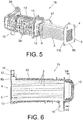
- the Figures 5 to 15 illustrate a first embodiment of the invention.
- the heat exchanger 1b comprises the same elements bearing the references 2 to 15 and 17 of the first and second embodiments.
- the inlet 4 of the gases should be arranged close to the passage of the cooling fluid, whether at the inlet or at the outlet.
- the inlet 4 of the gas is located near the inlet 14 of the refrigerant.
- the duct bundle 3 is fixed at its free end to the metal support plate 8b, and at its closed end to the storage tank. gas 12.
- said support plate 8b is fixed at the open end of the plastic casing 13 by means of screws.
- a plastic seal 17 is further provided between the open end of the carcass 13 and the support plate 8b to provide the required level of sealing.
- the plastic casing 13 is fixed at its closed end to said metal gas reservoir 12 by means of joining which comprise a plurality of longitudinal ribs 18 with a small contact surface, integral with the plastic casing 13 and capable of being nested in corresponding orifices 19 formed in the gas reservoir 12, as shown for example by the Figures 7 to 9 .
- the orifices 19 are formed in said gas tank by stamping.
- the longitudinal ribs 18 make it possible to solve the problem of having both an area sufficiently small to maintain the temperature in the contact zone of the plastic material at values close to the temperature of the coolant, and a sufficiently large contact zone. to be able to support the metal body.
- this solution makes it possible to obtain an abundant flow of the coolant to cool the contact zone which is at an elevated temperature.
- the connecting means comprise six longitudinal ribs 18 symmetrically distributed, so that each large side of said rectangular cross section comprises two ribs and each small side comprises a rib.
- the connecting means comprise four longitudinal ribs 18 distributed symmetrically, so that each large side of said rectangular cross section comprises two ribs.
- the joining means comprise two longitudinal ribs 18 distributed symmetrically, so that each long side of said rectangular cross section comprises a rib.
- the longitudinal ribs 18 have a minimum longitudinal dimension to allow the displacements due to the different thermal expansion between the metal gas tank 12 and the plastic casing 13, thus ensuring proper operation of the exchanger.
- the arrow with two points shown on the figure 10 indicates the direction of these longitudinal displacements.
- a minimum distance between the gas tank 12 and the plastic casing 13 is also provided, depending on the minimum cross-sectional area of the refrigerant flow in the exchanger 1b. This ensures an abundant flow of refrigerant.
- This minimum distance between the gas reservoir 12 and the plastic casing 13, measured on each opposite side of the gas reservoir 12, is twice the distance between the gas conduits 3.
- a safety distance is also provided, equal to between 1.5 and 2.5 times the minimum cross section of the refrigerant flow.
- the outlet fitting 15 of the refrigerant fluid is located near the contact zone of the junction between the carcass 13 and the gas reservoir 12, as shown by FIGS. figures 6 and 10 . This guarantees a minimum refrigerant flow.
- the exchanger 1b comprises mounting brackets 20 to a surface of the engine environment, which are located close to said contact zone of the junction between the carcass 13 and the gas reservoir 12, as shown in FIG. figure 5 . In this way, a better resistance of the metal body to the vibrations due to the motor is obtained.
- the longitudinal ribs 18 comprise a suitable configuration to absorb the clearance due to the tolerances of the gas reservoir 12 and the plastic casing 13.
- the longitudinal ribs 18 will admit a minor deformation of the plastic material if the interference of assembly between the two components exceeds the allowable interference, that is to say if the gas tank has the greatest permissible tolerance and that the distance between the longitudinal ribs is as small as possible.
- the longitudinal ribs 18 may comprise a branched configuration, as shown by the Figures 11 to 14 .
- the longitudinal ribs 18 comprise two diverging branches which form a suitable angle chosen as a function of the plastics material used.
- the longitudinal ribs 18 comprise three diverging branches.
- the addition of an additional central branch makes it possible to improve the stability.
- the longitudinal ribs 18 may comprise a plurality of small protuberances 21 on their outer surface, as shown in FIG. figure 15 .
- the volume of plastic to be deformed is thus less, in the event of interference of assembly, and, consequently, the mounting procedure is facilitated.
- the invention can also be applied to stacked plate heat exchangers.
- the gas circuit may be of the "U" -shaped type (the gas inlet and outlet are arranged at the same end) or of the linear type (the inlet and the outlet gases are arranged at opposite ends).
- the heat exchanger 1c comprises the same elements bearing the references 2 to 15 and 17 of the previous embodiments.
- the support plate 8c is joined to a metal flange 22, which is coupled in direct contact with the open end of the plastic casing 13 by means of screws and a plastic seal 17 to secure the sealing of the refrigerant.
- a seal 23 is provided between the metal flange 22 and the valve.
- Said seal 23 is made of a heat-insulating material, preferably of mica, thus reducing the heat transfer from the valve to the plastic casing 13. Furthermore, said seal 23 has a shape that coincides with the shape of the rim 22, as shown in figure 16 .
- the seal 23 is able to withstand a high temperature up to about 950 oC, which allows the temperature in contact with the plastic casing 13 to be reduced to about 50oC.
- the seal 23 reduces the temperature level, thus ensuring the durability of the EGR exchanger, and, more importantly, it increases the range of plastics that can be used with the carcass . In addition, the cost of production is reduced.
- the invention can also be applied to stacked plate heat exchangers.
- the gas circuit may be of the "U" -shaped type (the gas inlet and outlet are arranged at the same end) or of the linear type (the inlet and the outlet gases are arranged at opposite ends).
- the heat exchanger 1d comprises the same elements bearing the references 2 to 15 of the previous embodiments.
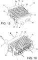
- the heat exchanger 1d consists of a carcass in plastic 13 which comprises in its interior a first circuit 3 EGR type provided with a bundle of conduits for cooling the engine exhaust gas, and a second circuit 3a of the type WCAC (Water Charge Air Coolers) provided with a conduit bundle for cooling the intake air of the engine, the two circuits 3, 3a being arranged adjacent.
- Each circuit 3, 3a is located on the figure 19 by means of a circle.
- the plastic casing 13 may have a free shape adapted to the environment, and the two circuits EGR 3 and WCAC 3a may be arranged relative to each other in different arrangements, for example in parallel, as shown in FIG. figure 1d , or in series, "L" shaped, "T” shaped, etc.
- the exchanger 1d is of linear type, that is to say that the inlet and the outlet of the gases are arranged at opposite ends.
- the inputs 4, 4a of each EGR circuit 3 and WCAC 3a are disposed at the same end of the carcass 13, while the outputs 5, 5a are disposed at the opposite end.
- the exchanger 1d comprises two support plates 8d, each of which is coupled to one end of the two circuits EGR 3 and WCAC 3a.
- the exchanger 1d also comprises two gas reservoirs 12, each of them being coupled to one end of the plastic casing 13.
- each gas tank 12 is manufactured in one piece integrating the inputs or outputs of each EGR circuit 3 and WCAC 3a.
- one of the gas tanks 12 comprises the respective inputs 4, 4a for each EGR circuit 3 and WCAC 3a; while the other gas tank 12 comprises the respective outlets 5, 5a for each EGR circuit 3 and WCAC 3a.
- the direction of the gas flow at the inlet and the outlet of the two circuits EGR 3 and WCAC 3a is indicated by arrows on the figure 19 .
- gas tank 12 can be divided into two parts, each of them being associated with an inlet or an outlet of each EGR circuit 3 and WCAC 3a.
- each EGR circuit 3 and WCAC 3a may be similar, and may also have different dimensions to better meet the requirements in terms of heat efficiency.
- the two beams EGR ducts 3 and WCAC 3a can be fixed together to the carcass 13 or using independent means to obtain a certain durability, for example to meet the requirements of thermal shock.
Landscapes
- Engineering & Computer Science (AREA)
- Physics & Mathematics (AREA)
- Thermal Sciences (AREA)
- Mechanical Engineering (AREA)
- General Engineering & Computer Science (AREA)
- Exhaust-Gas Circulating Devices (AREA)
- Heat-Exchange Devices With Radiators And Conduit Assemblies (AREA)
Claims (1)
- Wärmetauscher (1b, 1c) für Gas, der einen Metallkern (2) umfasst, der eine Anordnung aus parallelen Leitungen (3) zur Zirkulation von Gas unter Wärmeaustausch mit einem Kühlfluid in U-Form, wobei der Eingang (4) und der Ausgang (5) des zu kühlenden Fluids benachbarte Positionen an ein und demselben offenen Ende (6) der Anordnung aus parallelen Leitungen (3) einnehmen, umfasst, wobei das gegenüberliegende Ende (7) geschlossen ist und einen vorwärtsführenden Kanal und einen rückführenden Kanal definiert, wobei der Kern (2) eine erste Stützplatte (8b, 8c), die bei dem offenen Ende (6) angeordnet und mit einem Rand (11b, 22) zur Verwendung mit einem Gehäuse versehen ist, und eine zweite Stützplatte (9), die bei dem geschlossenen Ende (7) angeordnet und mit einem verschlossenen metallischen Gasbehälter (12) verbunden ist, umfasst, wobei jede Stützplatte (8b, 8c, 9) durch Laserschweißung mit mindestens einem Ende der Anordnung aus parallelen Leitungen (3) verbunden ist, wobei der Gasbehälter (12) direkt mit der Stützplatte (9) verbunden ist, wobei der Kern (2) in einem Gehäuse (13), das aus Kunststoff hergestellt und mit einem Kühlfluidkreis verbunden ist, gelagert ist, dadurch gekennzeichnet, dass das Gehäuse (13) an seinem geschlossenen Ende durch Verbindungsmittel, die mehrere Längsrippen (18) mit einer geringen Kontaktfläche, die mit dem Gehäuse (13) fest verbunden sind und in entsprechende in dem Gasbehälter (12) vorgesehene Öffnungen (19) passen, umfassen, an dem metallischen Gasbehälter (12) fixiert ist, und dass der Gasbehälter (12) durch Laserschweißung oder Lichtbogenschweißung mit der Stützplatte (9) verbunden ist.
Applications Claiming Priority (5)
| Application Number | Priority Date | Filing Date | Title |
|---|---|---|---|
| ES200700987A ES2325348B1 (es) | 2007-04-13 | 2007-04-13 | Intercambiador de calor para gases, y su correspondiente procedimiento de fabricacion. |
| ES200703136A ES2332253B1 (es) | 2007-11-27 | 2007-11-27 | Intercambiador de calor para gases, en especial de los gases de escape de un motor. |
| ES200703278A ES2333191B1 (es) | 2007-12-12 | 2007-12-12 | Intercambiador de calor para gases, en especial de los gases de escape de un motor. |
| ES200703279A ES2334480B1 (es) | 2007-12-12 | 2007-12-12 | Intercambiador de calor para gases. |
| PCT/EP2008/053893 WO2008125485A1 (fr) | 2007-04-13 | 2008-04-01 | Echangeur de chaleur pour gaz, et son procede de fabrication correspondant |
Publications (2)
| Publication Number | Publication Date |
|---|---|
| EP2137477A1 EP2137477A1 (de) | 2009-12-30 |
| EP2137477B1 true EP2137477B1 (de) | 2018-09-12 |
Family
ID=39709014
Family Applications (1)
| Application Number | Title | Priority Date | Filing Date |
|---|---|---|---|
| EP08735663.0A Active EP2137477B1 (de) | 2007-04-13 | 2008-04-01 | Wärmetauscher für gas |
Country Status (3)
| Country | Link |
|---|---|
| EP (1) | EP2137477B1 (de) |
| KR (1) | KR101554048B1 (de) |
| WO (1) | WO2008125485A1 (de) |
Families Citing this family (17)
| Publication number | Priority date | Publication date | Assignee | Title |
|---|---|---|---|---|
| JP2010112201A (ja) * | 2008-11-04 | 2010-05-20 | Tokyo Radiator Mfg Co Ltd | Uターン型egrクーラ |
| JP2010127171A (ja) * | 2008-11-27 | 2010-06-10 | Tokyo Radiator Mfg Co Ltd | Uターン型egrクーラ |
| DE102009050884A1 (de) * | 2009-10-27 | 2011-04-28 | Behr Gmbh & Co. Kg | Abgaswärmetauscher |
| WO2012052465A1 (en) * | 2010-10-19 | 2012-04-26 | Dsm Ip Assets B.V. | Heat exchanger manifold end tank |
| ES2397882B1 (es) * | 2010-12-22 | 2013-10-17 | Valeo Térmico, S.A. | Intercambiador de calor de placas apiladas. |
| FR2977306B1 (fr) * | 2011-06-30 | 2017-12-15 | Valeo Systemes Thermiques | Echangeur thermique notamment pour vehicule automobile |
| DE102011113788A1 (de) * | 2011-09-20 | 2013-03-21 | Friedrich Boysen Gmbh & Co. Kg | Wärmeübertragungsanordnung |
| DE102012204121A1 (de) * | 2012-03-15 | 2013-09-19 | Mahle International Gmbh | Ladeluftkühleinrichtung |
| DE102012208771A1 (de) * | 2012-05-24 | 2013-11-28 | Behr Gmbh & Co. Kg | Wärmetauscher zum Temperieren eines ersten Fluids unter Verwendung eines zweiten Fluids |
| DE102013213031A1 (de) * | 2012-07-03 | 2014-05-22 | Behr Gmbh & Co. Kg | Stutzen |
| DE102013006956B4 (de) * | 2013-04-23 | 2020-06-04 | Mann+Hummel Gmbh | Luftführendes Bauteil mit einem Ladeluftkühler |
| DE102013221151A1 (de) * | 2013-10-17 | 2015-04-23 | MAHLE Behr GmbH & Co. KG | Wärmeübertrager |
| DE102014209323A1 (de) * | 2014-05-16 | 2015-11-19 | Mahle International Gmbh | Kunststoffbauteil |
| KR102206182B1 (ko) * | 2016-11-09 | 2021-01-21 | 항저우 산후아 리서치 인스티튜트 컴퍼니 리미티드 | 차량의 유체 열교환 조립체 및 열관리 시스템 |
| DE102017130153B4 (de) | 2017-12-15 | 2022-12-29 | Hanon Systems | Vorrichtung zur Wärmeübertragung und Verfahren zum Herstellen der Vorrichtung |
| US11428473B2 (en) * | 2019-02-01 | 2022-08-30 | Modine Manufacturing Company | Heat exchanger |
| EP4425083A1 (de) * | 2023-02-28 | 2024-09-04 | Hamilton Sundstrand Corporation | Wärmetauscher-wenderingabschnitt |
Family Cites Families (9)
| Publication number | Priority date | Publication date | Assignee | Title |
|---|---|---|---|---|
| JPH1113551A (ja) * | 1997-06-23 | 1999-01-19 | Isuzu Motors Ltd | Egrクーラ |
| JP4130512B2 (ja) * | 1998-04-24 | 2008-08-06 | ベール ゲゼルシャフト ミット ベシュレンクテル ハフツング ウント コンパニー | 熱交換器 |
| JP2000213425A (ja) * | 1999-01-20 | 2000-08-02 | Hino Motors Ltd | Egrク―ラ |
| MY121525A (en) * | 1999-03-11 | 2006-01-28 | Nippon Catalytic Chem Ind | Shell-and tube heat exchanger and method for inhibiting polymerization in the shell-and-tube heat exchanger |
| DE10228246A1 (de) * | 2002-06-25 | 2004-01-15 | Behr Gmbh & Co. | Abgaswärmeübertrager und Verfahren zu seiner Herstellung |
| ES2260971B1 (es) * | 2003-06-20 | 2008-02-16 | Valeo Termico, S.A. | Intercambiador de calor para gases, en especial de los gases de escape de un motor. |
| DE20316688U1 (de) * | 2003-10-29 | 2004-03-11 | Behr Gmbh & Co. Kg | Wärmetauscher |
| WO2007048603A2 (de) * | 2005-10-26 | 2007-05-03 | Behr Gmbh & Co. Kg | Wärmetauscher, verfahren zur herstellung eines wärmetauschers |
| DE102006031606A1 (de) * | 2006-07-06 | 2008-01-17 | Behr Gmbh & Co. Kg | Wärmetauscher zur Abgaskühlung, Verfahren zur Herstellung eines Wärmetauschers |
-
2008
- 2008-04-01 EP EP08735663.0A patent/EP2137477B1/de active Active
- 2008-04-01 KR KR1020097021124A patent/KR101554048B1/ko active IP Right Grant
- 2008-04-01 WO PCT/EP2008/053893 patent/WO2008125485A1/fr active Application Filing
Non-Patent Citations (1)
| Title |
|---|
| None * |
Also Published As
| Publication number | Publication date |
|---|---|
| KR101554048B1 (ko) | 2015-09-17 |
| KR20100015470A (ko) | 2010-02-12 |
| EP2137477A1 (de) | 2009-12-30 |
| WO2008125485A1 (fr) | 2008-10-23 |
Similar Documents
| Publication | Publication Date | Title |
|---|---|---|
| EP2137477B1 (de) | Wärmetauscher für gas | |
| EP2972049B1 (de) | Wärmetauscher, insbesondere supraladender luftkühler | |
| EP2817503B1 (de) | Wärmetauscher für gase, im besonderen für motorabgase | |
| EP2856058B1 (de) | Wärmetauscher mit verstärktem kollektor | |
| FR2949554A1 (fr) | Echangeur thermique | |
| WO2011061090A2 (fr) | Echangeur de chaleur pour gaz, notamment pour les gaz d'echappement d'un moteur | |
| EP2912396B1 (de) | Wärmetauscher, insbesondere für ein kraftfahrzeug | |
| EP2227667B1 (de) | Wärmetauscher für gase, insbesondere für das abgas aus einem motor | |
| WO2008049648A1 (fr) | Echangeur de chaleur pour gaz et son procede de fabrication correspondant | |
| EP2208010B1 (de) | Wärmetauscher für hoch- und tief-temperaturmedien | |
| WO2014095580A1 (fr) | Echangeur de chaleur entre un liquide caloporteur et un fluide refrigerant, notamment pour vehicule automobile | |
| EP2877804A1 (de) | Wärmetauscher für ein kraftfahrzeug mit einem befestigungsflansch | |
| FR2924162A1 (fr) | Bride d'assemblage d'au moins un element avant avec au moins un element arriere d'un dispositif d'echappement | |
| EP2901097B1 (de) | Wärmetauscher, insbesondere für kraftfahrzeug, und dazugehöriges montageverfahren | |
| EP2400140B1 (de) | Gaswärmetauscher, insbesondere für die Abgase eines Motors | |
| WO2011064090A2 (fr) | Echangeur de chaleur a plaques empilees | |
| EP3394416A1 (de) | Gasleitungseinheit mit partikelfilteranordnung, verfahren zur herstellung davon und wärmetauscher für gas, insbesondere für motorabgase | |
| EP2469210B1 (de) | Wärmetauscher mit gestapelten Platten | |
| WO2011029940A1 (fr) | Échangeur de chaleur pour gaz, particulièrement pour les gaz d'échappement d'un moteur | |
| WO2016097136A1 (fr) | Echangeur de chaleur comprenant des moyens permettant d'ameliorer l'etancheite dudit echangeur de chaleur | |
| FR3139191A1 (fr) | Système de connexion fluidique pour un échangeur de chaleur | |
| FR2833691A1 (fr) | Support de fixation pour echangeur de chaleur brase | |
| FR3039264A1 (fr) | Boitier pour un echangeur de chaleur et echangeur de chaleur comprenant ledit boitier | |
| FR2975766A1 (fr) | Echangeur thermique |
Legal Events
| Date | Code | Title | Description |
|---|---|---|---|
| PUAI | Public reference made under article 153(3) epc to a published international application that has entered the european phase |
Free format text: ORIGINAL CODE: 0009012 |
|
| 17P | Request for examination filed |
Effective date: 20090929 |
|
| AK | Designated contracting states |
Kind code of ref document: A1 Designated state(s): AT BE BG CH CY CZ DE DK EE ES FI FR GB GR HR HU IE IS IT LI LT LU LV MC MT NL NO PL PT RO SE SI SK TR |
|
| DAX | Request for extension of the european patent (deleted) | ||
| 17Q | First examination report despatched |
Effective date: 20150615 |
|
| STAA | Information on the status of an ep patent application or granted ep patent |
Free format text: STATUS: EXAMINATION IS IN PROGRESS |
|
| GRAP | Despatch of communication of intention to grant a patent |
Free format text: ORIGINAL CODE: EPIDOSNIGR1 |
|
| STAA | Information on the status of an ep patent application or granted ep patent |
Free format text: STATUS: GRANT OF PATENT IS INTENDED |
|
| INTG | Intention to grant announced |
Effective date: 20180419 |
|
| GRAS | Grant fee paid |
Free format text: ORIGINAL CODE: EPIDOSNIGR3 |
|
| GRAA | (expected) grant |
Free format text: ORIGINAL CODE: 0009210 |
|
| STAA | Information on the status of an ep patent application or granted ep patent |
Free format text: STATUS: THE PATENT HAS BEEN GRANTED |
|
| AK | Designated contracting states |
Kind code of ref document: B1 Designated state(s): AT BE BG CH CY CZ DE DK EE ES FI FR GB GR HR HU IE IS IT LI LT LU LV MC MT NL NO PL PT RO SE SI SK TR |
|
| REG | Reference to a national code |
Ref country code: GB Ref legal event code: FG4D Free format text: NOT ENGLISH |
|
| REG | Reference to a national code |
Ref country code: CH Ref legal event code: EP |
|
| REG | Reference to a national code |
Ref country code: IE Ref legal event code: FG4D Free format text: LANGUAGE OF EP DOCUMENT: FRENCH |
|
| REG | Reference to a national code |
Ref country code: AT Ref legal event code: REF Ref document number: 1041097 Country of ref document: AT Kind code of ref document: T Effective date: 20181015 |
|
| REG | Reference to a national code |
Ref country code: DE Ref legal event code: R096 Ref document number: 602008056938 Country of ref document: DE |
|
| REG | Reference to a national code |
Ref country code: NL Ref legal event code: MP Effective date: 20180912 |
|
| REG | Reference to a national code |
Ref country code: LT Ref legal event code: MG4D |
|
| PG25 | Lapsed in a contracting state [announced via postgrant information from national office to epo] |
Ref country code: GR Free format text: LAPSE BECAUSE OF FAILURE TO SUBMIT A TRANSLATION OF THE DESCRIPTION OR TO PAY THE FEE WITHIN THE PRESCRIBED TIME-LIMIT Effective date: 20181213 Ref country code: NO Free format text: LAPSE BECAUSE OF FAILURE TO SUBMIT A TRANSLATION OF THE DESCRIPTION OR TO PAY THE FEE WITHIN THE PRESCRIBED TIME-LIMIT Effective date: 20181212 Ref country code: BG Free format text: LAPSE BECAUSE OF FAILURE TO SUBMIT A TRANSLATION OF THE DESCRIPTION OR TO PAY THE FEE WITHIN THE PRESCRIBED TIME-LIMIT Effective date: 20181212 Ref country code: FI Free format text: LAPSE BECAUSE OF FAILURE TO SUBMIT A TRANSLATION OF THE DESCRIPTION OR TO PAY THE FEE WITHIN THE PRESCRIBED TIME-LIMIT Effective date: 20180912 Ref country code: LT Free format text: LAPSE BECAUSE OF FAILURE TO SUBMIT A TRANSLATION OF THE DESCRIPTION OR TO PAY THE FEE WITHIN THE PRESCRIBED TIME-LIMIT Effective date: 20180912 Ref country code: SE Free format text: LAPSE BECAUSE OF FAILURE TO SUBMIT A TRANSLATION OF THE DESCRIPTION OR TO PAY THE FEE WITHIN THE PRESCRIBED TIME-LIMIT Effective date: 20180912 |
|
| PG25 | Lapsed in a contracting state [announced via postgrant information from national office to epo] |
Ref country code: ES Free format text: LAPSE BECAUSE OF FAILURE TO SUBMIT A TRANSLATION OF THE DESCRIPTION OR TO PAY THE FEE WITHIN THE PRESCRIBED TIME-LIMIT Effective date: 20180912 Ref country code: LV Free format text: LAPSE BECAUSE OF FAILURE TO SUBMIT A TRANSLATION OF THE DESCRIPTION OR TO PAY THE FEE WITHIN THE PRESCRIBED TIME-LIMIT Effective date: 20180912 Ref country code: HR Free format text: LAPSE BECAUSE OF FAILURE TO SUBMIT A TRANSLATION OF THE DESCRIPTION OR TO PAY THE FEE WITHIN THE PRESCRIBED TIME-LIMIT Effective date: 20180912 |
|
| REG | Reference to a national code |
Ref country code: AT Ref legal event code: MK05 Ref document number: 1041097 Country of ref document: AT Kind code of ref document: T Effective date: 20180912 |
|
| PG25 | Lapsed in a contracting state [announced via postgrant information from national office to epo] |
Ref country code: PL Free format text: LAPSE BECAUSE OF FAILURE TO SUBMIT A TRANSLATION OF THE DESCRIPTION OR TO PAY THE FEE WITHIN THE PRESCRIBED TIME-LIMIT Effective date: 20180912 Ref country code: EE Free format text: LAPSE BECAUSE OF FAILURE TO SUBMIT A TRANSLATION OF THE DESCRIPTION OR TO PAY THE FEE WITHIN THE PRESCRIBED TIME-LIMIT Effective date: 20180912 Ref country code: AT Free format text: LAPSE BECAUSE OF FAILURE TO SUBMIT A TRANSLATION OF THE DESCRIPTION OR TO PAY THE FEE WITHIN THE PRESCRIBED TIME-LIMIT Effective date: 20180912 Ref country code: IS Free format text: LAPSE BECAUSE OF FAILURE TO SUBMIT A TRANSLATION OF THE DESCRIPTION OR TO PAY THE FEE WITHIN THE PRESCRIBED TIME-LIMIT Effective date: 20190112 Ref country code: IT Free format text: LAPSE BECAUSE OF FAILURE TO SUBMIT A TRANSLATION OF THE DESCRIPTION OR TO PAY THE FEE WITHIN THE PRESCRIBED TIME-LIMIT Effective date: 20180912 Ref country code: NL Free format text: LAPSE BECAUSE OF FAILURE TO SUBMIT A TRANSLATION OF THE DESCRIPTION OR TO PAY THE FEE WITHIN THE PRESCRIBED TIME-LIMIT Effective date: 20180912 Ref country code: RO Free format text: LAPSE BECAUSE OF FAILURE TO SUBMIT A TRANSLATION OF THE DESCRIPTION OR TO PAY THE FEE WITHIN THE PRESCRIBED TIME-LIMIT Effective date: 20180912 |
|
| PG25 | Lapsed in a contracting state [announced via postgrant information from national office to epo] |
Ref country code: PT Free format text: LAPSE BECAUSE OF FAILURE TO SUBMIT A TRANSLATION OF THE DESCRIPTION OR TO PAY THE FEE WITHIN THE PRESCRIBED TIME-LIMIT Effective date: 20190112 Ref country code: SK Free format text: LAPSE BECAUSE OF FAILURE TO SUBMIT A TRANSLATION OF THE DESCRIPTION OR TO PAY THE FEE WITHIN THE PRESCRIBED TIME-LIMIT Effective date: 20180912 |
|
| REG | Reference to a national code |
Ref country code: DE Ref legal event code: R097 Ref document number: 602008056938 Country of ref document: DE |
|
| PLBE | No opposition filed within time limit |
Free format text: ORIGINAL CODE: 0009261 |
|
| STAA | Information on the status of an ep patent application or granted ep patent |
Free format text: STATUS: NO OPPOSITION FILED WITHIN TIME LIMIT |
|
| PG25 | Lapsed in a contracting state [announced via postgrant information from national office to epo] |
Ref country code: DK Free format text: LAPSE BECAUSE OF FAILURE TO SUBMIT A TRANSLATION OF THE DESCRIPTION OR TO PAY THE FEE WITHIN THE PRESCRIBED TIME-LIMIT Effective date: 20180912 |
|
| 26N | No opposition filed |
Effective date: 20190613 |
|
| PG25 | Lapsed in a contracting state [announced via postgrant information from national office to epo] |
Ref country code: SI Free format text: LAPSE BECAUSE OF FAILURE TO SUBMIT A TRANSLATION OF THE DESCRIPTION OR TO PAY THE FEE WITHIN THE PRESCRIBED TIME-LIMIT Effective date: 20180912 |
|
| REG | Reference to a national code |
Ref country code: CH Ref legal event code: PL |
|
| REG | Reference to a national code |
Ref country code: BE Ref legal event code: MM Effective date: 20190430 |
|
| GBPC | Gb: european patent ceased through non-payment of renewal fee |
Effective date: 20190401 |
|
| PG25 | Lapsed in a contracting state [announced via postgrant information from national office to epo] |
Ref country code: MC Free format text: LAPSE BECAUSE OF FAILURE TO SUBMIT A TRANSLATION OF THE DESCRIPTION OR TO PAY THE FEE WITHIN THE PRESCRIBED TIME-LIMIT Effective date: 20180912 Ref country code: LU Free format text: LAPSE BECAUSE OF NON-PAYMENT OF DUE FEES Effective date: 20190401 |
|
| PG25 | Lapsed in a contracting state [announced via postgrant information from national office to epo] |
Ref country code: CH Free format text: LAPSE BECAUSE OF NON-PAYMENT OF DUE FEES Effective date: 20190430 Ref country code: LI Free format text: LAPSE BECAUSE OF NON-PAYMENT OF DUE FEES Effective date: 20190430 Ref country code: GB Free format text: LAPSE BECAUSE OF NON-PAYMENT OF DUE FEES Effective date: 20190401 |
|
| PG25 | Lapsed in a contracting state [announced via postgrant information from national office to epo] |
Ref country code: BE Free format text: LAPSE BECAUSE OF NON-PAYMENT OF DUE FEES Effective date: 20190430 |
|
| PG25 | Lapsed in a contracting state [announced via postgrant information from national office to epo] |
Ref country code: TR Free format text: LAPSE BECAUSE OF FAILURE TO SUBMIT A TRANSLATION OF THE DESCRIPTION OR TO PAY THE FEE WITHIN THE PRESCRIBED TIME-LIMIT Effective date: 20180912 |
|
| PG25 | Lapsed in a contracting state [announced via postgrant information from national office to epo] |
Ref country code: IE Free format text: LAPSE BECAUSE OF NON-PAYMENT OF DUE FEES Effective date: 20190401 |
|
| PG25 | Lapsed in a contracting state [announced via postgrant information from national office to epo] |
Ref country code: CY Free format text: LAPSE BECAUSE OF FAILURE TO SUBMIT A TRANSLATION OF THE DESCRIPTION OR TO PAY THE FEE WITHIN THE PRESCRIBED TIME-LIMIT Effective date: 20180912 |
|
| PG25 | Lapsed in a contracting state [announced via postgrant information from national office to epo] |
Ref country code: MT Free format text: LAPSE BECAUSE OF FAILURE TO SUBMIT A TRANSLATION OF THE DESCRIPTION OR TO PAY THE FEE WITHIN THE PRESCRIBED TIME-LIMIT Effective date: 20180912 Ref country code: HU Free format text: LAPSE BECAUSE OF FAILURE TO SUBMIT A TRANSLATION OF THE DESCRIPTION OR TO PAY THE FEE WITHIN THE PRESCRIBED TIME-LIMIT; INVALID AB INITIO Effective date: 20080401 |
|
| PGFP | Annual fee paid to national office [announced via postgrant information from national office to epo] |
Ref country code: CZ Payment date: 20220322 Year of fee payment: 15 |
|
| P01 | Opt-out of the competence of the unified patent court (upc) registered |
Effective date: 20230603 |
|
| PG25 | Lapsed in a contracting state [announced via postgrant information from national office to epo] |
Ref country code: CZ Free format text: LAPSE BECAUSE OF NON-PAYMENT OF DUE FEES Effective date: 20230401 |
|
| PGFP | Annual fee paid to national office [announced via postgrant information from national office to epo] |
Ref country code: DE Payment date: 20240409 Year of fee payment: 17 |
|
| PGFP | Annual fee paid to national office [announced via postgrant information from national office to epo] |
Ref country code: FR Payment date: 20240423 Year of fee payment: 17 |