EP2901097B1 - Wärmetauscher, insbesondere für kraftfahrzeug, und dazugehöriges montageverfahren - Google Patents
Wärmetauscher, insbesondere für kraftfahrzeug, und dazugehöriges montageverfahren Download PDFInfo
- Publication number
- EP2901097B1 EP2901097B1 EP13766334.0A EP13766334A EP2901097B1 EP 2901097 B1 EP2901097 B1 EP 2901097B1 EP 13766334 A EP13766334 A EP 13766334A EP 2901097 B1 EP2901097 B1 EP 2901097B1
- Authority
- EP
- European Patent Office
- Prior art keywords
- casing
- fluid
- bundle
- heat exchanger
- flat tubes
- Prior art date
- Legal status (The legal status is an assumption and is not a legal conclusion. Google has not performed a legal analysis and makes no representation as to the accuracy of the status listed.)
- Not-in-force
Links
Images

Classifications
-
- F—MECHANICAL ENGINEERING; LIGHTING; HEATING; WEAPONS; BLASTING
- F28—HEAT EXCHANGE IN GENERAL
- F28F—DETAILS OF HEAT-EXCHANGE AND HEAT-TRANSFER APPARATUS, OF GENERAL APPLICATION
- F28F9/00—Casings; Header boxes; Auxiliary supports for elements; Auxiliary members within casings
- F28F9/02—Header boxes; End plates
- F28F9/0219—Arrangements for sealing end plates into casing or header box; Header box sub-elements
-
- F—MECHANICAL ENGINEERING; LIGHTING; HEATING; WEAPONS; BLASTING
- F28—HEAT EXCHANGE IN GENERAL
- F28D—HEAT-EXCHANGE APPARATUS, NOT PROVIDED FOR IN ANOTHER SUBCLASS, IN WHICH THE HEAT-EXCHANGE MEDIA DO NOT COME INTO DIRECT CONTACT
- F28D7/00—Heat-exchange apparatus having stationary tubular conduit assemblies for both heat-exchange media, the media being in contact with different sides of a conduit wall
- F28D7/16—Heat-exchange apparatus having stationary tubular conduit assemblies for both heat-exchange media, the media being in contact with different sides of a conduit wall the conduits being arranged in parallel spaced relation
- F28D7/1684—Heat-exchange apparatus having stationary tubular conduit assemblies for both heat-exchange media, the media being in contact with different sides of a conduit wall the conduits being arranged in parallel spaced relation the conduits having a non-circular cross-section
-
- F—MECHANICAL ENGINEERING; LIGHTING; HEATING; WEAPONS; BLASTING
- F28—HEAT EXCHANGE IN GENERAL
- F28F—DETAILS OF HEAT-EXCHANGE AND HEAT-TRANSFER APPARATUS, OF GENERAL APPLICATION
- F28F9/00—Casings; Header boxes; Auxiliary supports for elements; Auxiliary members within casings
- F28F9/02—Header boxes; End plates
- F28F9/0219—Arrangements for sealing end plates into casing or header box; Header box sub-elements
- F28F9/0221—Header boxes or end plates formed by stacked elements
Definitions
- the invention relates to a heat exchanger, in particular for a motor vehicle.
- the invention also relates to methods of assembling such a heat exchanger.
- a heat exchanger for example used in the automotive industry and more specifically in an internal combustion engine of a motor vehicle, comprises heat exchange elements and fluid flow in which heat exchanging fluids circulate. between them.
- the heat exchange elements may for example comprise tubes or plates, gas flow disturbing fins and / or fluid flow disruptors or the like.
- Exchangers comprising a bundle of flat tubes arranged parallel to one another on one or more parallel rows with one another, these tubes being arranged to allow the circulation of a first fluid between said flat tubes and, on the other hand, to allow the circulation a second fluid inside said flat tubes, exchanging heat with the first fluid.
- a known structure of such a bundle is a stack of flat tubes with enlarged ends, the flat tubes being fixed together at their widened ends.
- the bundle of flat tubes is contained inside a casing connected to a circuit of the first fluid and delimiting the space of circulating said first fluid between the flat tubes.
- the ends of the bundle and housing are also generally connected to a manifold and an inlet housing and an outlet housing of the second fluid for the circulation of the second fluid within the flat tubes.
- Such an exchanger is described for example in the document EP 1 574 802 A .
- Many fluid associations can be envisaged, be they liquids and / or gases.
- the invention therefore aims to at least partially meet the disadvantages of the prior art and to provide an inexpensive heat exchanger and ensuring an optimum seal between the circulation of the first and second fluid.
- the fixing groove is directly formed between the at least one flaring of the casing and the end of the bundle makes it possible to simplify the assembly of the heat exchanger as well as to limit manufacturing costs by limiting the number of parts. necessary for its assembly.
- the housing comprises four independent walls fixed to each other and forming said housing.
- the independent walls are fixed together by brazing.
- the housing is brazed to the beam.
- the widened ends of the flat tubes have a rectangular cross-sectional shape.
- the inlet and the outlet of the first fluid are formed on the same wall of the housing.
- the fixing groove comprises a sealing means.
- At least two flares of said at least one flare at each end of the casing comprise folded release appendages on the inlet casing or the output casing of the second fluid.
- the heat exchanger is configured to cool the charge air of an engine in a motor vehicle.
- Such a method allows a reduction in production costs by simplifying the fixing steps of the inlet and outlet housings within the fixing groove.
- the latter comprises, between the step of sealing the flat beam inside the housing and the step of sealing the inlet housing of the second fluid outlet box in the housing. fixing groove, an additional step of setting up a sealing means in the fixing groove.
- the formation of said at least one flare at the ends of the casing is made by stamping.
- the casing comprises four independent walls forming said casing and that the fixing of said four independent walls is carried out during the step of sealing the beam inside the casing.
- the step of sealing the beam inside the housing is carried out by brazing.
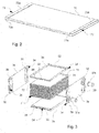
- the figure 1a shows a heat exchanger 1 for the transfer of heat between a first and a second fluid, comprising a housing 3 provided with an inlet 37a and an outlet 37b of the first fluid.
- the heat exchanger 1 comprises an inlet casing 5a and an outlet casing 5b of the second fluid.
- the housing 3 further comprises at its ends intended to be connected, a flare 32 forming a fixing groove 34 (not visible on the figure 1a but visible on the figure 1b ) in which is inserted the inlet housing 5a or 5b outlet of the second fluid.
- At least two flares 32 at each end of the casing 3 may include locking appendages 38 in order to maintain the inlet casing 5a and the outlet casing 5b in the fixing groove 34.
- the figure 1b shows in more detail the interior of the heat exchanger 1 without the presence of the arrival boxes 5a and 5b output of the second fluid.
- the exchanger 1 comprises within it a beam 7 composed of flat tubes 70 stacked on each other.
- the flat tubes 70 have enlarged ends 72.
- the widened ends 72 for example substantially rectangular in cross section, are fixed together to form the stack of flat tubes 70 constituting the beam 7, the attachment between the ends widened 72 of the flat tubes 70 being joined.
- the casing 3 surrounds said beam 7 and is fixed thereto in a sealed manner so as to delimit a sealed enclosure, in which the first fluid may circulate in the interstices 74 (visible in FIG. figure 3 and 4 ) between the flat tubes 70 of said bundle 7.
- the flat tubes 70 are preferably made of metal, their widened ends 72 can thus be made by stamping.
- the enlargement height may be of the order of 1 mm so that the gaps 74 have a height of the order of 2mm and also to limit the stretching of material at the extended ends 72.
- Fixing said flat tubes 70 between them to form the beam 7, can be made by brazing.
- the casing 3 may be more particularly fixed to the beam 7 at the side surfaces 72b of the flat tubes 70 and on the flat surface 72a of the widened ends 72 of the flat tubes 70 at the top and at the base of the beam 7.
- the casing 3 may be in particular attached to the beam 7 only at the widened ends 72 of the flat tubes 70, a space between the housing 3 and the side surfaces 72b being left in order to allow the flow of the first fluid over the entire height of the beam 7.
- the casing 3 is fixed over the entire length of the lateral surfaces 72b of the flat tubes 70 and to allow the circulation of the first fluid over the entire height of the beam 7, the casing 3 comprises stampings 39 (visible on the Figures 1a, 1b and 3 ).
- the inlet 37a and outlet 37b of the first fluid are preferably made on the walls of the casing 3 facing the interstices 74 between the flat tubes 70 of the bundle 7, so that the first fluid passes through the latter in order to allow a good heat exchange.
- the inlet 37a and outlet 37b of the first fluid may in particular be made on opposite walls or on the same wall of the casing 3. In the case where the casing 3 comprises stampings 39, said inlet 37a and outlet 37b of the first fluid may be performed on these.
- the housing 3 may preferably be made of metal and its attachment with the beam 7 when the latter is metallic, be made by brazing.
- the figure 3 shows an alternative embodiment where the casing 3 comprises four independent walls 3a, 3b, 3c and 3d, for example metallic, fixed to each other, for example by brazing, and forming said casing 3.
- These independent walls 3a, 3b, 3c and 3d can thus be fixed to each other at the time of attachment of the beam 7 with the housing 3, allowing a good fit of the housing 3 around the beam 7 and cost savings.
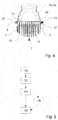
- the figure 4 shows in sectional view, one end of a heat exchanger 1. It is thus possible to see that the fixing groove 34 is formed on one side by the flare 32 of the housing 3 and the other by the end of the beam 7.
- the inlet casing 5a or outlet 5b of the second fluid thus fits into the fixing groove 34 to guide the second fluid in the beam 7, inside the flat tubes 70.
- the fixing groove 34 may further comprise a sealing means 9 placed inside thereof in order to improve the sealing and / or fixing of the 5a and 5b output casings of the second fluid.
- This sealing means 9 may for example be a seal or glue.
- the inlet casings 5a and 5b of the outlet are inserted into the fixing groove 34 and their attachment can be achieved by gluing or crimping.
- the blocking means 38 may be, for example, appendages of the casing 3 folded onto said inlet 5a and outlet 5b casings (as shown in FIGS. Figures 1a, 1b , 3 and 4 ) or tie rods and strengthen the attachment and maintenance of said arrival boxes 5a and 5b output.
- the arrival boxes 5a and 5b output can also be metal and thus can be fixed for example by welding.
- the heat exchanger 1 can particularly be configured to cool the charge air of an engine in a motor vehicle.
- the charge air corresponding to the second fluid, arrives at the arrival box 5a, and passes into the beam 7, inside the flat tubes 70.
- a heat transfer fluid for example a water and glycol mixture, acting first fluid and from a cooling circuit, enters through the inlet 37a, circulates between the flat tubes 70 of the beam 7 inside the casing 3.
- a second step 102 of the assembly process corresponds to the formation of a flare 32 at the ends of the casing 3, for example by stamping the latter or the four independent walls 3a, 3b, 3c and 3d.
- the third step 104 of the assembly process corresponds to the sealed fastening of the beam 7 inside the casing 3.
- This attachment is made at the widened ends 72 of the flat tubes 70, so that the flaring 32 at the ends of the casing 3, in cooperation with the ends of the beam 7, forms a fixing groove 34, and that said casing 3 delimits a sealed enclosure in which a first fluid flows between the flat tubes 70 of the beam 7 from an inlet 37a to an outlet 37b of the first fluid.
- This attachment can be made for example by soldering if the housing 3 and the beam 7 are both metallic.
- the housing 3 comprises four independent walls 3a, 3b, 3c and 3d
- the latter are fixed to each other during this third step 104. It is the same in the case where the flat tubes 70 of the beam 7 are not fixed between them.
- the four independent walls 3a, 3b, 3c and 3d and the beam 7 are fixed together. allowing an adjustment of the different parts between them and thus to guarantee a good sealing.
- the assembly method may comprise, following the third fixing step 104, an optional step 106 of placing a sealing means 9 inside the fixing groove 34, for example a gasket or glue.
- a fourth step 108 corresponds to the sealed attachment of the inlet casing 5a and the outlet casing 5b of the second fluid in the fixing groove 34, so that the second fluid circulates inside the flat tubes 70 of the bundle 7.
- This fixing is carried out in particular by insertion of said inlet boxes 5a and 5b outlet in the fixing groove 34.
- the arrival boxes 5a and 5b output can be glued, crimped or welded if they are metal and their attachment reinforced by the locking means 38.
- Such a method makes it possible to reduce production costs by simplifying the fixing steps of the arrival boxes 5a and of the outlet boxes 5b within the fixing groove 34.
Landscapes
- Engineering & Computer Science (AREA)
- Physics & Mathematics (AREA)
- Thermal Sciences (AREA)
- Mechanical Engineering (AREA)
- General Engineering & Computer Science (AREA)
- Heat-Exchange Devices With Radiators And Conduit Assemblies (AREA)
Claims (14)
- Wärmetauscher (1) zur Übertragung von Wärme zwischen einem ersten und einem zweiten Fluid, wobei der Wärmetauscher umfasst:- ein Bündel (7) von flachen Rohren (70) mit verbreiterten Enden (72), wobei sich die verbreiterten Enden (72) in direktem Kontakt miteinander befinden und auf dichte Weise aneinander befestigt sind,- ein Gehäuse (3), welches das Bündel (7) umgibt und auf dichte Weise an den verbreiterten Enden (72) der flachen Rohre (70) befestigt ist, wobei das Gehäuse (3) eine dichte Kammer begrenzt, in welcher das erste Fluid zwischen den flachen Rohren (70) des Bündels (7) von einem Eingang (37a) zu einem Ausgang (37b) des ersten Fluids strömt,- einen Eintrittskasten (5a) und einen Austrittskasten (5b) für das zweite Fluid, wobei diese Kästen (5a, 5b) an den Enden des Bündels (7) positioniert sind und auf dichte Weise an den Enden des Gehäuses (3) befestigt sind, wobei das zweite Fluid im Inneren der flachen Rohre (70) des Bündels (7) strömt,dadurch gekennzeichnet, dass die Enden des Gehäuses (3) wenigstens eine Erweiterung (32) an jedem Ende aufweisen, wobei die wenigstens eine Erweiterung (32) im Zusammenwirken mit den Enden des Bündels (7) eine Befestigungsrille (34) bildet, in welche der Eintrittskasten (5a) oder der Austrittskasten (5b) für das zweite Fluid eingesetzt ist.
- Wärmetauscher (1) nach Anspruch 1, dadurch gekennzeichnet, dass das Gehäuse (3) vier unabhängige Wände (3a, 3b, 3c, 3d) aufweist, die aneinander befestigt sind und das Gehäuse (3) bilden.
- Wärmetauscher (1) nach dem vorhergehenden Anspruch, dadurch gekennzeichnet, dass die unabhängigen Wände (3a, 3b, 3c, 3d) durch Löten aneinander befestigt sind.
- Wärmetauscher (1) nach einem der vorhergehenden Ansprüche, dadurch gekennzeichnet, dass das Gehäuse (3) durch Löten an dem Bündel (7) befestigt ist.
- Wärmetauscher (1) nach einem der vorhergehenden Ansprüche, dadurch gekennzeichnet, dass die verbreiterten Enden (72) der flachen Rohre (70) eine rechteckige Form aufweisen.
- Wärmetauscher (1) nach einem der vorhergehenden Ansprüche, dadurch gekennzeichnet, dass der Eingang (37a) und der Ausgang (37b) des ersten Fluids an ein und derselben Wand des Gehäuses (3) ausgebildet sind.
- Wärmetauscher (1) nach einem der vorhergehenden Ansprüche, dadurch gekennzeichnet, dass die Befestigungsrille (34) ein Dichtmittel (9) aufweist.
- Wärmetauscher (1) nach einem der vorhergehenden Ansprüche, dadurch gekennzeichnet, dass wenigstens zwei Erweiterungen (32) der wenigstens einen Erweiterung (32) pro Ende des Gehäuses (3) Verriegelungsfortsätze (38) aufweisen, die auf dem Eintrittskasten (5a) oder dem Austrittskasten (5b) für das zweite Fluid umgebogen sind.
- Wärmetauscher (1) nach einem der vorhergehenden Ansprüche, dadurch gekennzeichnet, dass er dafür ausgebildet ist, die Ladeluft eines Motors in einem Kraftfahrzeug zu kühlen.
- Montageverfahren für einen Wärmetauscher (1) zur Übertragung von Wärme zwischen einem ersten und einem zweiten Fluid, welcher umfasst:- ein Bündel (7) von flachen Rohren (70) mit verbreiterten Enden (72), wobei sich die verbreiterten Enden (72) in direktem Kontakt miteinander befinden und auf dichte Weise aneinander befestigt sind,- ein Gehäuse (3),- einen Eintrittskasten (5a) und einen Austrittskasten (5b) für das zweite Fluid,wobei das Verfahren die folgenden Schritte umfasst:- Ausbildung wenigstens einer Erweiterung (32) an jedem Ende des Gehäuses (3),- dichte Befestigung des Bündels (7) im Inneren des Gehäuses (3) an den verbreiterten Enden (72) der flachen Rohre (70), derart, dass die wenigstens eine Erweiterung (32) an jedem Ende des Gehäuses (3) im Zusammenwirken mit den Enden des Bündels (7) eine Befestigungsrille (34) bildet, und dadurch, dass das Gehäuse (3) eine dichte Kammer begrenzt, in welcher ein erstes Fluid zwischen den flachen Rohren (70) des Bündels (7) von einem Eingang (37a) zu einem Ausgang (37b) des ersten Fluids strömt,- Einsetzen und dichte Befestigung des Eintrittskastens (5a) und des Austrittskastens (5b) für das zweite Fluid in der Befestigungsrille (34), derart, dass das zweite Fluid im Inneren der flachen Rohre (70) des Bündels (7) strömt.
- Montageverfahren nach Anspruch 10, dadurch gekennzeichnet, dass es zwischen dem Schritt der dichten Befestigung des flachen Bündels (7) im Inneren des Gehäuses (3) und dem Schritt der dichten Befestigung des Eintrittskastens (5a) und des Austrittskastens (5b) für das zweite Fluid in der Befestigungsrille (34) einen zusätzlichen Schritt der Anbringung eines Dichtmittels (9) in der Befestigungsrille (34) umfasst.
- Montageverfahren nach einem der Ansprüche 10 oder 11, dadurch gekennzeichnet, dass die Ausbildung der wenigstens einen Erweiterung (32) an den Enden des Gehäuses (3) durch Ziehen durchgeführt wird.
- Montageverfahren nach einem der Ansprüche 10 bis 12, dadurch gekennzeichnet, dass das Gehäuse (3) vier unabhängige Wände (3a, 3b, 3c, 3d) aufweist, die das Gehäuse (3) bilden, und dass die Befestigung dieser vier unabhängigen Abschnitte (3a, 3b, 3c, 3d) während des Schrittes der dichten Befestigung des Bündels (7) im Inneren des Gehäuses (3) durchgeführt wird.
- Montageverfahren nach einem der Ansprüche 10 bis 13, dadurch gekennzeichnet, dass der Schritt der dichten Befestigung des Bündels (7) im Inneren des Gehäuses (3) durch Löten ausgeführt wird.
Applications Claiming Priority (2)
| Application Number | Priority Date | Filing Date | Title |
|---|---|---|---|
| FR1259165A FR2996295B1 (fr) | 2012-09-28 | 2012-09-28 | Echangeur de chaleur, notamment pour vehicule automobile, et procede d'assemblage associe. |
| PCT/EP2013/069920 WO2014048959A1 (fr) | 2012-09-28 | 2013-09-25 | Echangeur de chaleur, notamment pour vehicule automobile, et procede d'assemblage associe |
Publications (2)
| Publication Number | Publication Date |
|---|---|
| EP2901097A1 EP2901097A1 (de) | 2015-08-05 |
| EP2901097B1 true EP2901097B1 (de) | 2017-07-19 |
Family
ID=47356126
Family Applications (1)
| Application Number | Title | Priority Date | Filing Date |
|---|---|---|---|
| EP13766334.0A Not-in-force EP2901097B1 (de) | 2012-09-28 | 2013-09-25 | Wärmetauscher, insbesondere für kraftfahrzeug, und dazugehöriges montageverfahren |
Country Status (3)
| Country | Link |
|---|---|
| EP (1) | EP2901097B1 (de) |
| FR (1) | FR2996295B1 (de) |
| WO (1) | WO2014048959A1 (de) |
Families Citing this family (2)
| Publication number | Priority date | Publication date | Assignee | Title |
|---|---|---|---|---|
| CN107687726B (zh) * | 2016-08-03 | 2020-10-27 | 杭州三花研究院有限公司 | 热交换装置 |
| DE102020203223A1 (de) * | 2020-03-12 | 2021-09-16 | Sgl Carbon Se | Plattenwärmetauscher |
Family Cites Families (5)
| Publication number | Priority date | Publication date | Assignee | Title |
|---|---|---|---|---|
| US4848448A (en) * | 1987-12-28 | 1989-07-18 | Mccord Heat Transfer Corporation | Heat exchange assembly |
| DE102004012358A1 (de) * | 2004-03-13 | 2005-09-29 | Dr.Ing.H.C. F. Porsche Ag | Wärmetauscher, insbesondere Ladeluftkühler für ein Kraftfahrzeug |
| US7195060B2 (en) * | 2005-04-01 | 2007-03-27 | Dana Canada Corporation | Stacked-tube heat exchanger |
| JP5321271B2 (ja) * | 2009-06-17 | 2013-10-23 | 株式会社デンソー | 高温ガス冷却用熱交換器 |
| FR2954481B1 (fr) * | 2009-12-18 | 2012-02-03 | Valeo Systemes Thermiques | Echangeur de chaleur |
-
2012
- 2012-09-28 FR FR1259165A patent/FR2996295B1/fr not_active Expired - Fee Related
-
2013
- 2013-09-25 EP EP13766334.0A patent/EP2901097B1/de not_active Not-in-force
- 2013-09-25 WO PCT/EP2013/069920 patent/WO2014048959A1/fr active Application Filing
Non-Patent Citations (1)
| Title |
|---|
| None * |
Also Published As
| Publication number | Publication date |
|---|---|
| FR2996295B1 (fr) | 2014-10-10 |
| WO2014048959A1 (fr) | 2014-04-03 |
| FR2996295A1 (fr) | 2014-04-04 |
| EP2901097A1 (de) | 2015-08-05 |
Similar Documents
| Publication | Publication Date | Title |
|---|---|---|
| EP2513585B1 (de) | Wärmetauscher | |
| EP2513586B1 (de) | Wärmetauscher | |
| EP2310789B1 (de) | Wärmetauscher | |
| EP2137477B1 (de) | Wärmetauscher für gas | |
| EP2972049B1 (de) | Wärmetauscher, insbesondere supraladender luftkühler | |
| EP2912396B1 (de) | Wärmetauscher, insbesondere für ein kraftfahrzeug | |
| EP2901097B1 (de) | Wärmetauscher, insbesondere für kraftfahrzeug, und dazugehöriges montageverfahren | |
| WO2015004032A1 (fr) | Echangeur de chaleur | |
| WO2018115692A1 (fr) | Échangeur de chaleur à plaque de renfort | |
| EP2877804A1 (de) | Wärmetauscher für ein kraftfahrzeug mit einem befestigungsflansch | |
| FR3039263B1 (fr) | Echangeur de chaleur comprenant un boitier et des moyens pour ameliorer l'etancheite dudit boitier | |
| EP3577408B1 (de) | Wärmetauscherkopf | |
| WO2009021826A1 (fr) | Echangeur de chaleur pour gaz et procede de fabrication correspondant | |
| FR3030709A1 (fr) | Echangeur de chaleur | |
| FR3069312B1 (fr) | Echangeur de chaleur pour refroidisseur d'air de suralimentation | |
| WO2011064090A2 (fr) | Echangeur de chaleur a plaques empilees | |
| WO2016097136A1 (fr) | Echangeur de chaleur comprenant des moyens permettant d'ameliorer l'etancheite dudit echangeur de chaleur | |
| FR2800451A1 (fr) | Echangeur de chaleur a encombrement reduit et equipement d'un vehicule automobile comportant un tel echangeur de chaleur | |
| WO2019180377A1 (fr) | Dispositif de refroidissement d'un air d'admission de moteur a combustion interne | |
| FR3039264A1 (fr) | Boitier pour un echangeur de chaleur et echangeur de chaleur comprenant ledit boitier | |
| WO2018060650A1 (fr) | Plaque collectrice, échangeur de chaleur et procédé de fabrication associé | |
| FR3049049A1 (fr) | Echangeur de chaleur, en particulier pour vehicule, plus particulierement pour des vehicules automobiles | |
| FR3069630A1 (fr) | Boite collectrice pour echangeur de chaleur et echangeur de chaleur associe |
Legal Events
| Date | Code | Title | Description |
|---|---|---|---|
| PUAI | Public reference made under article 153(3) epc to a published international application that has entered the european phase |
Free format text: ORIGINAL CODE: 0009012 |
|
| 17P | Request for examination filed |
Effective date: 20150416 |
|
| AK | Designated contracting states |
Kind code of ref document: A1 Designated state(s): AL AT BE BG CH CY CZ DE DK EE ES FI FR GB GR HR HU IE IS IT LI LT LU LV MC MK MT NL NO PL PT RO RS SE SI SK SM TR |
|
| AX | Request for extension of the european patent |
Extension state: BA ME |
|
| DAX | Request for extension of the european patent (deleted) | ||
| GRAP | Despatch of communication of intention to grant a patent |
Free format text: ORIGINAL CODE: EPIDOSNIGR1 |
|
| INTG | Intention to grant announced |
Effective date: 20170206 |
|
| GRAS | Grant fee paid |
Free format text: ORIGINAL CODE: EPIDOSNIGR3 |
|
| GRAA | (expected) grant |
Free format text: ORIGINAL CODE: 0009210 |
|
| AK | Designated contracting states |
Kind code of ref document: B1 Designated state(s): AL AT BE BG CH CY CZ DE DK EE ES FI FR GB GR HR HU IE IS IT LI LT LU LV MC MK MT NL NO PL PT RO RS SE SI SK SM TR |
|
| REG | Reference to a national code |
Ref country code: GB Ref legal event code: FG4D Free format text: NOT ENGLISH |
|
| REG | Reference to a national code |
Ref country code: CH Ref legal event code: EP |
|
| REG | Reference to a national code |
Ref country code: IE Ref legal event code: FG4D Free format text: LANGUAGE OF EP DOCUMENT: FRENCH |
|
| REG | Reference to a national code |
Ref country code: AT Ref legal event code: REF Ref document number: 910797 Country of ref document: AT Kind code of ref document: T Effective date: 20170815 |
|
| REG | Reference to a national code |
Ref country code: DE Ref legal event code: R096 Ref document number: 602013023783 Country of ref document: DE |
|
| REG | Reference to a national code |
Ref country code: NL Ref legal event code: MP Effective date: 20170719 |
|
| REG | Reference to a national code |
Ref country code: LT Ref legal event code: MG4D |
|
| REG | Reference to a national code |
Ref country code: AT Ref legal event code: MK05 Ref document number: 910797 Country of ref document: AT Kind code of ref document: T Effective date: 20170719 |
|
| PG25 | Lapsed in a contracting state [announced via postgrant information from national office to epo] |
Ref country code: FI Free format text: LAPSE BECAUSE OF FAILURE TO SUBMIT A TRANSLATION OF THE DESCRIPTION OR TO PAY THE FEE WITHIN THE PRESCRIBED TIME-LIMIT Effective date: 20170719 Ref country code: HR Free format text: LAPSE BECAUSE OF FAILURE TO SUBMIT A TRANSLATION OF THE DESCRIPTION OR TO PAY THE FEE WITHIN THE PRESCRIBED TIME-LIMIT Effective date: 20170719 Ref country code: NL Free format text: LAPSE BECAUSE OF FAILURE TO SUBMIT A TRANSLATION OF THE DESCRIPTION OR TO PAY THE FEE WITHIN THE PRESCRIBED TIME-LIMIT Effective date: 20170719 Ref country code: AT Free format text: LAPSE BECAUSE OF FAILURE TO SUBMIT A TRANSLATION OF THE DESCRIPTION OR TO PAY THE FEE WITHIN THE PRESCRIBED TIME-LIMIT Effective date: 20170719 Ref country code: NO Free format text: LAPSE BECAUSE OF FAILURE TO SUBMIT A TRANSLATION OF THE DESCRIPTION OR TO PAY THE FEE WITHIN THE PRESCRIBED TIME-LIMIT Effective date: 20171019 Ref country code: SE Free format text: LAPSE BECAUSE OF FAILURE TO SUBMIT A TRANSLATION OF THE DESCRIPTION OR TO PAY THE FEE WITHIN THE PRESCRIBED TIME-LIMIT Effective date: 20170719 Ref country code: LT Free format text: LAPSE BECAUSE OF FAILURE TO SUBMIT A TRANSLATION OF THE DESCRIPTION OR TO PAY THE FEE WITHIN THE PRESCRIBED TIME-LIMIT Effective date: 20170719 |
|
| PG25 | Lapsed in a contracting state [announced via postgrant information from national office to epo] |
Ref country code: LV Free format text: LAPSE BECAUSE OF FAILURE TO SUBMIT A TRANSLATION OF THE DESCRIPTION OR TO PAY THE FEE WITHIN THE PRESCRIBED TIME-LIMIT Effective date: 20170719 Ref country code: BG Free format text: LAPSE BECAUSE OF FAILURE TO SUBMIT A TRANSLATION OF THE DESCRIPTION OR TO PAY THE FEE WITHIN THE PRESCRIBED TIME-LIMIT Effective date: 20171019 Ref country code: ES Free format text: LAPSE BECAUSE OF FAILURE TO SUBMIT A TRANSLATION OF THE DESCRIPTION OR TO PAY THE FEE WITHIN THE PRESCRIBED TIME-LIMIT Effective date: 20170719 Ref country code: RS Free format text: LAPSE BECAUSE OF FAILURE TO SUBMIT A TRANSLATION OF THE DESCRIPTION OR TO PAY THE FEE WITHIN THE PRESCRIBED TIME-LIMIT Effective date: 20170719 Ref country code: IS Free format text: LAPSE BECAUSE OF FAILURE TO SUBMIT A TRANSLATION OF THE DESCRIPTION OR TO PAY THE FEE WITHIN THE PRESCRIBED TIME-LIMIT Effective date: 20171119 Ref country code: PL Free format text: LAPSE BECAUSE OF FAILURE TO SUBMIT A TRANSLATION OF THE DESCRIPTION OR TO PAY THE FEE WITHIN THE PRESCRIBED TIME-LIMIT Effective date: 20170719 Ref country code: GR Free format text: LAPSE BECAUSE OF FAILURE TO SUBMIT A TRANSLATION OF THE DESCRIPTION OR TO PAY THE FEE WITHIN THE PRESCRIBED TIME-LIMIT Effective date: 20171020 |
|
| REG | Reference to a national code |
Ref country code: DE Ref legal event code: R119 Ref document number: 602013023783 Country of ref document: DE |
|
| PG25 | Lapsed in a contracting state [announced via postgrant information from national office to epo] |
Ref country code: DK Free format text: LAPSE BECAUSE OF FAILURE TO SUBMIT A TRANSLATION OF THE DESCRIPTION OR TO PAY THE FEE WITHIN THE PRESCRIBED TIME-LIMIT Effective date: 20170719 Ref country code: CZ Free format text: LAPSE BECAUSE OF FAILURE TO SUBMIT A TRANSLATION OF THE DESCRIPTION OR TO PAY THE FEE WITHIN THE PRESCRIBED TIME-LIMIT Effective date: 20170719 Ref country code: RO Free format text: LAPSE BECAUSE OF FAILURE TO SUBMIT A TRANSLATION OF THE DESCRIPTION OR TO PAY THE FEE WITHIN THE PRESCRIBED TIME-LIMIT Effective date: 20170719 |
|
| REG | Reference to a national code |
Ref country code: CH Ref legal event code: PL |
|
| PLBE | No opposition filed within time limit |
Free format text: ORIGINAL CODE: 0009261 |
|
| STAA | Information on the status of an ep patent application or granted ep patent |
Free format text: STATUS: NO OPPOSITION FILED WITHIN TIME LIMIT |
|
| PG25 | Lapsed in a contracting state [announced via postgrant information from national office to epo] |
Ref country code: EE Free format text: LAPSE BECAUSE OF FAILURE TO SUBMIT A TRANSLATION OF THE DESCRIPTION OR TO PAY THE FEE WITHIN THE PRESCRIBED TIME-LIMIT Effective date: 20170719 Ref country code: SM Free format text: LAPSE BECAUSE OF FAILURE TO SUBMIT A TRANSLATION OF THE DESCRIPTION OR TO PAY THE FEE WITHIN THE PRESCRIBED TIME-LIMIT Effective date: 20170719 Ref country code: SK Free format text: LAPSE BECAUSE OF FAILURE TO SUBMIT A TRANSLATION OF THE DESCRIPTION OR TO PAY THE FEE WITHIN THE PRESCRIBED TIME-LIMIT Effective date: 20170719 Ref country code: MC Free format text: LAPSE BECAUSE OF FAILURE TO SUBMIT A TRANSLATION OF THE DESCRIPTION OR TO PAY THE FEE WITHIN THE PRESCRIBED TIME-LIMIT Effective date: 20170719 Ref country code: IT Free format text: LAPSE BECAUSE OF FAILURE TO SUBMIT A TRANSLATION OF THE DESCRIPTION OR TO PAY THE FEE WITHIN THE PRESCRIBED TIME-LIMIT Effective date: 20170719 |
|
| 26N | No opposition filed |
Effective date: 20180420 |
|
| GBPC | Gb: european patent ceased through non-payment of renewal fee |
Effective date: 20171019 |
|
| REG | Reference to a national code |
Ref country code: IE Ref legal event code: MM4A |
|
| REG | Reference to a national code |
Ref country code: BE Ref legal event code: MM Effective date: 20170930 |
|
| PG25 | Lapsed in a contracting state [announced via postgrant information from national office to epo] |
Ref country code: LU Free format text: LAPSE BECAUSE OF NON-PAYMENT OF DUE FEES Effective date: 20170925 |
|
| REG | Reference to a national code |
Ref country code: FR Ref legal event code: ST Effective date: 20180531 |
|
| PG25 | Lapsed in a contracting state [announced via postgrant information from national office to epo] |
Ref country code: CH Free format text: LAPSE BECAUSE OF NON-PAYMENT OF DUE FEES Effective date: 20170930 Ref country code: LI Free format text: LAPSE BECAUSE OF NON-PAYMENT OF DUE FEES Effective date: 20170930 Ref country code: IE Free format text: LAPSE BECAUSE OF NON-PAYMENT OF DUE FEES Effective date: 20170925 Ref country code: GB Free format text: LAPSE BECAUSE OF NON-PAYMENT OF DUE FEES Effective date: 20171019 Ref country code: DE Free format text: LAPSE BECAUSE OF NON-PAYMENT OF DUE FEES Effective date: 20180404 |
|
| PG25 | Lapsed in a contracting state [announced via postgrant information from national office to epo] |
Ref country code: SI Free format text: LAPSE BECAUSE OF FAILURE TO SUBMIT A TRANSLATION OF THE DESCRIPTION OR TO PAY THE FEE WITHIN THE PRESCRIBED TIME-LIMIT Effective date: 20170719 Ref country code: BE Free format text: LAPSE BECAUSE OF NON-PAYMENT OF DUE FEES Effective date: 20170930 Ref country code: FR Free format text: LAPSE BECAUSE OF NON-PAYMENT OF DUE FEES Effective date: 20171002 |
|
| PG25 | Lapsed in a contracting state [announced via postgrant information from national office to epo] |
Ref country code: MT Free format text: LAPSE BECAUSE OF FAILURE TO SUBMIT A TRANSLATION OF THE DESCRIPTION OR TO PAY THE FEE WITHIN THE PRESCRIBED TIME-LIMIT Effective date: 20170719 |
|
| PG25 | Lapsed in a contracting state [announced via postgrant information from national office to epo] |
Ref country code: HU Free format text: LAPSE BECAUSE OF FAILURE TO SUBMIT A TRANSLATION OF THE DESCRIPTION OR TO PAY THE FEE WITHIN THE PRESCRIBED TIME-LIMIT; INVALID AB INITIO Effective date: 20130925 |
|
| PG25 | Lapsed in a contracting state [announced via postgrant information from national office to epo] |
Ref country code: CY Free format text: LAPSE BECAUSE OF FAILURE TO SUBMIT A TRANSLATION OF THE DESCRIPTION OR TO PAY THE FEE WITHIN THE PRESCRIBED TIME-LIMIT Effective date: 20170719 |
|
| PG25 | Lapsed in a contracting state [announced via postgrant information from national office to epo] |
Ref country code: MK Free format text: LAPSE BECAUSE OF FAILURE TO SUBMIT A TRANSLATION OF THE DESCRIPTION OR TO PAY THE FEE WITHIN THE PRESCRIBED TIME-LIMIT Effective date: 20170719 |
|
| PG25 | Lapsed in a contracting state [announced via postgrant information from national office to epo] |
Ref country code: TR Free format text: LAPSE BECAUSE OF FAILURE TO SUBMIT A TRANSLATION OF THE DESCRIPTION OR TO PAY THE FEE WITHIN THE PRESCRIBED TIME-LIMIT Effective date: 20170719 |
|
| PG25 | Lapsed in a contracting state [announced via postgrant information from national office to epo] |
Ref country code: PT Free format text: LAPSE BECAUSE OF FAILURE TO SUBMIT A TRANSLATION OF THE DESCRIPTION OR TO PAY THE FEE WITHIN THE PRESCRIBED TIME-LIMIT Effective date: 20170719 |
|
| PG25 | Lapsed in a contracting state [announced via postgrant information from national office to epo] |
Ref country code: AL Free format text: LAPSE BECAUSE OF FAILURE TO SUBMIT A TRANSLATION OF THE DESCRIPTION OR TO PAY THE FEE WITHIN THE PRESCRIBED TIME-LIMIT Effective date: 20170719 |