EP2709037A2 - Gehäuse für biometrischen Sensor - Google Patents
Gehäuse für biometrischen Sensor Download PDFInfo
- Publication number
- EP2709037A2 EP2709037A2 EP12198286.2A EP12198286A EP2709037A2 EP 2709037 A2 EP2709037 A2 EP 2709037A2 EP 12198286 A EP12198286 A EP 12198286A EP 2709037 A2 EP2709037 A2 EP 2709037A2
- Authority
- EP
- European Patent Office
- Prior art keywords
- sensor
- biometric sensor
- enclosure
- biometric
- secondary surface
- Prior art date
- Legal status (The legal status is an assumption and is not a legal conclusion. Google has not performed a legal analysis and makes no representation as to the accuracy of the status listed.)
- Ceased
Links
Images


Classifications
-
- G—PHYSICS
- G06—COMPUTING; CALCULATING OR COUNTING
- G06V—IMAGE OR VIDEO RECOGNITION OR UNDERSTANDING
- G06V40/00—Recognition of biometric, human-related or animal-related patterns in image or video data
- G06V40/10—Human or animal bodies, e.g. vehicle occupants or pedestrians; Body parts, e.g. hands
- G06V40/12—Fingerprints or palmprints
- G06V40/13—Sensors therefor
- G06V40/1329—Protecting the fingerprint sensor against damage caused by the finger
-
- A—HUMAN NECESSITIES
- A47—FURNITURE; DOMESTIC ARTICLES OR APPLIANCES; COFFEE MILLS; SPICE MILLS; SUCTION CLEANERS IN GENERAL
- A47B—TABLES; DESKS; OFFICE FURNITURE; CABINETS; DRAWERS; GENERAL DETAILS OF FURNITURE
- A47B81/00—Cabinets or racks specially adapted for other particular purposes, e.g. for storing guns or skis
-
- G—PHYSICS
- G06—COMPUTING; CALCULATING OR COUNTING
- G06V—IMAGE OR VIDEO RECOGNITION OR UNDERSTANDING
- G06V40/00—Recognition of biometric, human-related or animal-related patterns in image or video data
- G06V40/10—Human or animal bodies, e.g. vehicle occupants or pedestrians; Body parts, e.g. hands
- G06V40/12—Fingerprints or palmprints
- G06V40/13—Sensors therefor
- G06V40/1312—Sensors therefor direct reading, e.g. contactless acquisition
-
- G—PHYSICS
- G06—COMPUTING; CALCULATING OR COUNTING
- G06V—IMAGE OR VIDEO RECOGNITION OR UNDERSTANDING
- G06V40/00—Recognition of biometric, human-related or animal-related patterns in image or video data
- G06V40/10—Human or animal bodies, e.g. vehicle occupants or pedestrians; Body parts, e.g. hands
- G06V40/14—Vascular patterns
Definitions
- the present subject matter relates, in general, to an enclosure for a biometric sensor and, particularly but not exclusively, to an enclosure for a palm sensor.
- a biometric sensor identifies a user by his physiological or behavioral characteristics, such as palm print, finger print, iris, and voice. Such characteristics are also referred to as biometric characteristics. After identification of the user, the biometric sensor authorizes the user to perform any requested action. For example, a palm print sensor may allow the user to enter restricted areas after authentication of physiological or behavioral characteristics of the user's palm.
- Biometric sensors are generally installed at various locations for ensuring security and access control management, such as in organizations for keeping track of employee's attendance and ensuring security of systems and networks, in personal devices for tracking proper usage, and in electronic commerce to prevent online frauds.
- the biometric sensors are generally placed in a holder that supports the sensor.
- the holder may indicate a proper position to the user from where the biometric sensor can easily detect the biometric characteristics.
- the holder may allow the user to place his palm in a field of view of the biometric sensor, so that the biometric sensor can easily capture an impression or an image of the palm.
- an enclosure for a biometric sensor comprises a cabinet having a plurality of surfaces.
- the biometric sensor is placed inside the cabinet on a holder fixed on a primary surface from amongst the plurality of the surfaces.
- a secondary surface from amongst the plurality of surfaces is opposite to the primary surface.
- the secondary surface is substantially transparent to the electromagnetic rays emitted by the biometric sensor.
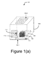
- Figure 1(a) illustrates a perspective view of an enclosure of a biometric sensor, in accordance with an embodiment of the present subject matter.
- Figures 1(b) and 1(c) illustrate positioning of the biometric sensor and a secondary surface at a predefined angle between each other, in accordance with an embodiment of the present subject matter.
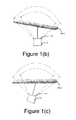
- Figures 1(d) and 1(e) illustrate the secondary surface having a curved shape, in accordance with an embodiment of the present subject matter.
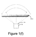
- Figure 1(f) illustrates a field of view of the biometric sensor, in accordance with an embodiment of the present subject matter.
- Figure 2 illustrates the secondary surface etched in a unique pattern, in accordance with an embodiment of the present subject matter.
- the present subject matter relates to an enclosure for a biometric sensor.
- the enclosure of the present subject matter conceals the biometric sensor to secure the biometric sensor from tampering, wear and tear, theft, and other factors, such as dust, moisture, and liquid spills.
- the biometric sensor may be a palm sensor, a finger print sensor, an iris sensor, a footprint sensor, a hand/feet geometry sensor, an ear lobe geometry sensor, a face biometric sensor, or any other biometric sensor which is used to authenticate a user based on his biometric characteristics.
- Most of the biometric sensors emit electromagnetic waves, specifically infrared (IR) rays, to obtain biometric characteristics of the user and have a suitable capture device, specifically an IR camera, to capture reflected rays that are indicative of the biometric characteristics of the user.
- IR infrared
- a palm vein sensor emits IR rays to obtain vein data of a palm.
- the IR rays fall on the palm, illuminating the blood vessels (veins), and are reflected back to the palm vein sensor.
- the reflected IR rays are in accordance with the impression of the palm and the veins.
- the reflected image of the palm and the veins, made by the IR rays, is captured by the IR camera inside the palm vein sensor.
- the palm vein sensor may send the vein image data, captured in the reflected IR rays of the palm to a system for authentication.
- the system for authentication as conventionally known, compares the vein data of a registered user with pre-stored registration data of the registered user to authenticate the registered user.
- the biometric sensor may emit near IR rays to capture the biometric characteristic of the user because of low attenuation characteristic of the near IR rays.
- most of the biometric sensors are kept exposed to the users or require direct contact with the user for accurate identification. Because of this exposure, there are always chances of tampering, vandalism, and theft.
- the biometric sensors are exposed to factors, such as dust, moisture, and liquid spills. Further, the exposed biometric sensors are more prone to wear and tear due to exposure to external conditions over long duration of time.
- the biometric sensors are located at manned and unmanned locations. At unmanned locations, it may not be possible to provide regular maintenance to the biometric sensors. Further, the biometric sensors at unmanned locations are more prone to theft, tampering, and vandalism.
- the user's biometric characteristic should be in the field of view of the IR camera of the biometric sensor and there should be an optimum distance between the biometric sensor and the biometric characteristic such that the biometric characteristic is within the focus of the biometric sensor and the biometric characteristic is captured accurately. Therefore, a holder or an enclosure is needed, which not only protects the biometric sensor from the abovementioned threats but also allows the biometric sensor to accurately capture the biometric characteristic of the user without any hindrance to the IR rays in its field of view.
- the biometric sensor is placed in a sensor holder.
- the sensor holder holds the biometric sensor and allows the biometric sensor to capture biometric characteristics without any direct contact with the user.
- the top surface of the sensor holder is kept open to avoid hindrance from path of the IR rays.
- the biometric sensor is placed in the sensor holder with placement marks or guides. The placement marks indicate a placement area at an optimum distance from where the biometric sensor can accurately capture the biometric characteristic of the user.
- the placement marks are made on edges of the sensor holder.
- the top surface is kept open to avoid any kind of hindrance to the IR rays.
- a glass enclosure may be used to conceal the biometric sensor.
- Use of the glass enclosure may help in avoiding situations where regular maintenance of the biometric sensor is required, but accuracy of the biometric sensor may get affected. This happens because glass is reflective in nature and amount of reflected rays depends on the angle of incidence, which makes a large part of the electromagnetic rays to reflect back rather than propagating through the glass. Due to this tendency of the glass, reflection of the biometric sensor is created when it tries to capture the impression of the user's biometric characteristic.
- the reflection of the electromagnetic rays from the glass, generated by the biometric sensor's emitters generally appears as big bright round objects, similar to light bulbs, in the image captured by the biometric sensor's camera. These reflections may interfere with an image having impression of the user's biometric characteristic. Therefore in the case of glass enclosure, the biometric characteristic is not captured accurately, which in turn deteriorates the accuracy of the biometric sensor placed in the glass enclosure.
- Conventional approaches to protect the biometric sensors using casings made of transparent materials, such as glass and acrylic have typically resulted in high false rejection and false acceptance rates, that consequently makes the biometric sensor, and in turn the authentication system, ineffective. In many cases, the authentication system rejects the image taken by the sensor.
- the present subject matter discloses an enclosure for a biometric sensor.
- the enclosure conceals the biometric sensor from a user and secures the biometric sensor from tampering, wear and tear, theft, moisture, dust, and liquid spills without affecting accuracy of the biometric sensor.
- the biometric sensor may emit electromagnetic rays to capture biometric characteristic of the user.
- the biometric sensor is a palm vein sensor, for example, Fujitsu PalmSecureTM Palm vein sensor may be concealed in the enclosure.
- the enclosure comprises a cabinet to hold the biometric sensor.
- the biometric sensor may be a palm print sensor, a palm vein sensor, or a finger print sensor.
- the cabinet is designed to conceal the biometric sensor from the user and various factors, such as dust, moisture, and liquid spills and to restrict any unwanted illuminations around the biometric sensor.
- the cabinet may be made up of material depending upon the requirements of the user.
- the cabinet may be a wooden cabinet to conceal the biometric sensor.
- the cabinet includes a plurality of surfaces which forms an enclosure to conceal the biometric sensor from the environmental factors and users.
- the biometric sensor may be placed on a holder, provided on a primary surface of the cabinet.
- the primary surface is one amongst the plurality of surfaces.
- the holder on the primary surface firmly holds the biometric sensor to provide stability to the biometric sensor in the cabinet.
- the holder may be designed to hold different types of sensors in the cabinet. For example, the holder may be designed in a cube shape to hold the palm vein sensor in the cabinet.
- a secondary surface is substantially transparent to electromagnetic rays emitted by the biometric sensor for authenticating a user based on his biometric characteristic.
- the biometric sensor may emit electromagnetic rays to capture the biometric characteristic of the user.
- the secondary surface may be kept opposite to the primary surface such that the electromagnetic rays emitted from the biometric sensors captures the biometric characteristic and reflect back to an electromagnetic ray capturing device of the biometric sensor. The secondary surface allows the electromagnetic rays emitted from the biometric sensor to pass through it.
- a clear glass, an etched glass, a partially etched glass, a clear glass with etching done in a unique pattern, a butter paper, a tracing paper, a translucent paper, a translucent plastic sheet, and an acrylic sheet may be used as the secondary surface.
- a single-side etched glass is used as the secondary surface in such a manner that the etched surface of the glass faces the biometric sensor.
- the secondary surface may be kept in a field of view of the biometric sensor at a predefined distance. The predefined distance may vary, depending upon the type of biometric sensor used.
- secondary surface is placed behind a hardened glass sheet to increase the strength of the enclosure, which may help in preventing theft and tampering of the biometric device.
- the secondary surface which allows the electromagnetic rays to pass through may be kept at a predefined angle from the top surface of the biometric sensor.
- the top surface of the biometric sensor may be defined as a surface from where the biometric sensor is emitting the electromagnetic rays.
- the biometric sensor may be placed on the holder such that the secondary surface of the enclosure and the top surface of the biometric sensor may have a predefined angle between them.
- This type of placement of the secondary surface with respect to the biometric sensor may help in preventing the reflected, from the secondary surface, electromagnetic rays from falling onto the capture device of the biometric sensor. This improves the accuracy of the biometric sensor concealed in the enclosure because now the image of the emitters is not visible in the captured biometric characteristic's image. It may be evident to a person skilled in the art that the various other placements of the secondary surface and the biometric sensor are also possible and may be implemented without deviating from the scope of the invention.
- the secondary surface may have a curved shape which may help in focusing the beam of the electromagnetic rays emitted from the biometric sensor to the camera of the biometric sensor.
- the secondary surface may have concave shape so that maximum electromagnetic rays having the biometric characteristic of the user fall onto the camera of the biometric sensor and the image of the emitters is out of the field of view of the biometric sensor.
- the plurality of surfaces other than the secondary surface may be coated to absorb unwanted illuminations around the biometric sensors.
- the unwanted illuminations may deteriorate accuracy of the biometric sensor by interfering with the rays.
- the unwanted illuminations may arise from external sources near to the enclosure.
- the unwanted illuminations from the external source may enter the cabinet and interfere with the electromagnetic rays which deteriorate the accuracy of the biometric sensor.
- the plurality of surfaces other than the secondary surface may be coated with matte finish black colour paint to absorb the unwanted illuminations in the cabinet.
- the coating may also help in absorbing unwanted rays originating from the biometric sensor. In absence of the coating, these unwanted rays may interfere with the electromagnetic rays by reflecting back from the other surfaces of the enclosure when biometric identification is being performed.
- a tertiary surface substantially transparent to the electromagnetic rays may be overlaid on either side of the secondary surface to improve overall strength, scratch resistance, reflectance, fingerprint or grease mark resistance, and disinfection of the secondary surface.
- the tertiary surface may be a thin film overlaid on the secondary surface.
- the thin film may be overlaid or coated on either side of the secondary surface.
- the thin film may be overlaid or coated on both sides of the secondary surface.
- the cabinet may be provided with a door having a locking mechanism for safely placing and removing the biometric sensor.
- the locking mechanism in the door may be used to lock the enclosure after placing the biometric sensor in the enclosure. This may help in securing the biometric sensor from tampering and theft.
- the cabinet is also provided with a vent or an outlet to allow passage of wires, of the biometric sensor, through, to connect with a computer system for authentication of the user and to perform actions requested by an authenticated user.
- the system may be defined as a host system which has pre-stored biometric characteristics of the users and an authentication mechanism to authenticate the users.
- the authenticated user may be defined as a user whose biometric characteristic matches with the pre-stored biometric characteristics in the system.
- the secondary surface may be attached to a proximity sensor to activate the biometric sensor.
- the biometric sensor may be activated when the biometric characteristic of the user is detected by the proximity sensor near to or on the secondary surface.
- the proximity sensor helps in avoiding unnecessary or early activation of the biometric sensor. This in turn also helps in reducing the power consumption of the biometric sensor.
- the biometric sensor may be activated when an authentication of a user is required and only after the user has placed the biometric characteristic correctly over or near the secondary surface.
- a touch switch or an IR sensor may be used in place of the proximity sensor to detect the presence of biometric characteristic of the user on or near the medium.
- biometric sensors may start the authentication of the user without identifying that whether the biometric characteristic of the user is present on the secondary surface or not. This may generate an error message.
- the proximity sensor overcomes this problem and the biometric sensor may be activated when the biometric characteristic is placed on the secondary surface correctly.
- the enclosure for the biometric sensor to secure the biometric sensor from tampering, wear and tear, theft and factors such as, dust, moisture, and liquid spills.
- the enclosure has been explained herein in context of the palm vein sensor.
- the concept explained in context thereto may be extended to any other biometric sensor and enclosure with different designs, without deviating from the scope and spirit of the invention.
- the enclosure may be designed in a cylindrical shape, with a top curved surface and a bottom curved surface, to secure a fingerprint sensor or a hand or earlobe geometry sensor.
- FIG. 1(a) illustrates a perspective view of an enclosure 100 of a biometric sensor 102, in accordance with an embodiment of the present subject matter.
- the enclosure 100 houses the biometric sensor 102.
- the enclosure 100 may be used to conceal various types of biometric sensors, for example, a palm sensor, a finger print sensor, an iris sensor, a footprint sensor, a hand/feet geometry sensor, an ear lobe geometry sensor, and a face biometric sensor.
- the biometric sensor 102 may have an electromagnetic ray transmitter (not shown in Figure) and a camera (not shown in Figure).
- the electromagnetic ray transmitter emits electromagnetic rays that are projected towards the biometric source, for example, a palm of a user to obtain biometric characteristic of the user.
- the biometric sensor 102 emits near IR rays because of their low attenuation characteristic.
- the electromagnetic rays are reflected from the biometric source back to the biometric sensor 102.
- the reflected electromagnetic rays comprise the biometric characteristic.
- the reflected electromagnetic rays are captured by the camera for authentication.
- the construction and operation of the biometric sensor 102 is conventionally known and thus is not elaborated herein in details for the sake of brevity of the present description.
- the enclosure 100 may be used to conceal and secure a palm vein sensor.
- the palm vein sensor emits near IR rays which when reflected from the palm of a user is indicative of vein data of the palm of the user. Accordingly, these near IR rays are projected on the palm and for obtaining the vein data in this case.
- An IR camera of the palm vein sensor captures the reflected near IR rays. For capturing the IR rays accurately, there should be no hindrance in the path of the near IR rays.
- Intensity of the IR rays of the biometric sensor 102 may, in one example, be set below a threshold value set by American Conference of Industrial Hygienists (ACGIH). For example, IR rays of intensity of about 10 mW/cm 2 (milliwatt per centimeter square) may be used to capture the biometric characteristic.
- ACGIH American Conference of Industrial Hygienists
- the enclosure 100 comprises a cabinet 104.
- the cabinet 104 is designed in such a way that it conceals the biometric sensor 102 from the users and other external factors.
- the cabinet 104 may be made up of different materials depending upon the requirements.
- the cabinet 104 may be made up of an alloy which has high strength and light weight.
- a wooden cabinet may be used to conceal the biometric sensor 102.
- the cabinet 104 may be designed depending upon the biometric sensor 102 to be placed.
- the cabinet 104 may have a cubical shape to enclose the palm vein sensor.
- the dimensions of the cabinet 104 may be in accordance with the size of the biometric sensor 102 and may vary based on the requirement.
- the cabinet 104 includes a plurality of surfaces which forms a housing to conceal the biometric sensor 102 from all sides.
- the plurality of surfaces includes a primary surface 106-1, a secondary surface 106-2, and other surfaces.
- the plurality of surfaces is hereinafter collectively referred to as the plurality of surfaces 106.
- the primary surface 106-1 and the secondary surface 106-2 from among the plurality of surfaces 106, are opposite to each other.
- the primary surface 106-1 and the secondary surface 106-2 are parallel to each other.
- the primary surface 106-1 and the secondary surface 106-2 may be adjacent to each other such that the biometric sensor 102 gets placed appropriately, as per its specifications, under the secondary surface 106-2, such that the biometric sensor 102 can capture the biometric characteristic properly.
- the biometric sensor 102 may be placed on a holder 108 fixed on the primary surface 106-1.
- the holder 108 may be designed based on type of the biometric sensor 102 to be placed in the cabinet 104.
- the holder 108 may be designed in a rectangular shape to hold the palm vein sensor.
- the holder 108 firmly grips the biometric sensor 102 to fix the biometric sensor 102 in the cabinet 104.
- the holder 108 may be placed in the center of the primary surface 106-1 and dimension of the holder 108 may be in accordance with dimension of the biometric sensor 102.
- the secondary surface 106-2 from amongst the plurality of surfaces 106 is substantially transparent to the rays.
- a clear glass, an etched glass, a butter paper, a tracing paper, a translucent paper, a translucent plastic sheet, and an acrylic sheet may be used as the secondary surface 106-2.
- other materials which allow the electromagnetic rays to pass through may also be used.
- the secondary surface 106-2 may be placed below a hardened glass sheet.
- the hardened glass sheet increases the strength of the secondary surface 106-2 in the enclosure 100 by providing additional support to the secondary surface 106-2, which protects the biometric sensor 102 from tampering, vandalism, and theft.
- the hardened glass sheet should not have any visible impurities, additives, aberrations, and bubbles in it.
- the impurities, additives, aberrations, and bubbles, if any, in the hardened glass sheet may deviate the electromagnetic rays coming from the biometric sensor 102 or the rays reflecting back from the biometric characteristic, in different directions and in turn may create distortions in an image taken by the biometric sensor 102, affecting the accuracy.
- the primary surface 106-1 and the secondary surface 106-2 of the cabinet 104 may be kept in a way to allow maximum propagation of the electromagnetic rays across the surface, i.e., most of the electromagnetic rays are able to pass through the secondary surface 106-2 without getting reflected or getting absorbed by the plurality of surfaces 106.
- the secondary surface 106-2 instead of using secondary surface 106-2 completely made of material which is transparent to the electromagnetic rays, only a certain portion of the secondary surface 106-2 may be made from the material transparent to the electromagnetic rays.
- the secondary surface 106-2 may be made from combination of materials which are transparent to the electromagnetic rays, i.e. it may consist of clear glass with etching done at some appropriate locations or in an appropriate pattern.
- the biometric sensor 102 may be embedded in a wall or in a door where the secondary surface 106-2 may be sufficient to conceal the biometric sensor 102.
- the secondary surface 106-2 may be sufficient to conceal the biometric sensor 102.
- structure of the wall or the door may cover the biometric sensor 102 from an outer side and the surface responsible for the emission of the electromagnetic rays may be considered as the secondary surface 106-2.
- a walls or door of the enclosure 100 may have a doubled layered structure such that the layer towards the exterior side serves as the enclosure wall and the layer towards the interior of the enclosure 100 acts as the secondary surface 106-2.
- surface of the wall or the door on which the holder 108 is placed to hold the biometric sensor 102 may be referred to as the primary surface 106-1.
- concealing the biometric sensor 102 in the enclosure 100 having the plurality of surfaces 106 and concealing the biometric sensor 102 by embedding the biometric sensor 102 in the wall or the door with the secondary surface 106-2 covering the surface responsible for the emission of the electromagnetic rays, it may be evident to a person having ordinary skill in the art that other embodiments of concealing the biometric sensor 102 are also possible.
- the secondary surface 106-2 and the surface of the biometric sensor 102 may be at an angle with respect to each other so that the reflection of the biometric sensor 102 and its emitters is not visible to the biometric sensor 102 or its camera.
- Figures 1(b) and 1(c) illustrate placement of a sensor of the biometric sensor 102, in accordance with an embodiment of the present subject matter.
- the secondary surface 106-2 may be kept at a predefined angle from a top surface 116 of the biometric sensor 102 such that the electromagnetic rays do not reflect, in high concentrations, back onto the biometric sensor 102 and reflection of the emitter may not be captured by the camera of the biometric sensor 102.
- the top surface 116 of the biometric sensor 102 may be defined as a surface from where the electromagnetic rays are emitted.
- the secondary surface 106-2 is tilted such that the secondary surface 106-2 and surface of the biometric sensor 102 are not parallel to each other and the secondary surface 106-2 is at an angle with respect to the secondary surface 106-2. To achieve this tilt, the enclosure 100 may be made such that the secondary surface 106-2 is affixed to the enclosure 100 at the top with a slight tilt.
- the biometric sensor 102 may be placed in such a way that the top surface 116 of the biometric sensor 102 and the secondary surface 106-2 are at the predefined angle. As depicted in Figure 1(c) , to achieve the tilt the biometric sensor 102 may be titled while the secondary surface 106-2 is straight. For example, the holder 108 on which the biometric sensor 102 is placed may be provided with a slope to achieve the angle.
- the angle may be any suitable angle between 0-90 degrees depending on various factors, such as the configuration of the biometric sensor 102 and the camera, the relative position of the biometric sensor 102 and the camera, and magnitude of illumination around the area of the biometric sensor 102.
- the predefined angle between the top surface 116 of the biometric sensor 102 and the secondary surface 106-2 may range from 3 degree to 35 degrees.
- the placement of the secondary surface 106-2 and the biometric sensor 102 helps in preventing a high concentration of the electromagnetic rays from reflecting back onto the camera of the biometric sensor 102. This may help in avoiding situation where an image of the emitter is captured by the camera of the biometric sensor 102.
- the secondary surface 106-2 may have a curved shape so as to avoid the direct reflections of the emitter coming back to the sensor of the biometric sensor 102.
- the secondary surface 106-2 may have a dome shape with a depression either towards the biometric sensor 102 or away from the biometric sensor 102.
- Figures 1(d) and 1(e) illustrate the secondary surface 106-2 having a curved shape, in accordance to an embodiment of the present subject matter.
- Figure 1(d) depicts the secondary surface 106-2 having a convex shape.
- the secondary surface 106-2 may have a concave shape, as shown in the Figure 1(e) .
- the curved shape of the secondary surface 106-2 may help in focusing the beam of the electromagnetic rays towards the camera of the biometric sensor 102.
- other shapes of the secondary surface 106-2 may be also possible, such as combination of convex shape and concave shape, which help in accurately capturing the biometric characteristics of the user.
- the secondary surface 106-2 may also be made of a clear glass.
- the angle or the curved or the dome shape helps in addressing the problems associated with the reflection of the rays from the secondary surface 106-2.
- the plurality of surfaces 106 other than the secondary 106-2 surface may be coated to avoid unwanted illuminations around the biometric sensor 102.
- the plurality of surfaces 106 other than the secondary surface 106-2 may be coated with matte finish black colour paint to avoid the unwanted illuminations.
- the matte finish black colour paint absorbs the unwanted illumination around the biometric sensor 102.
- illumination around the biometric sensor 102 should not exceed 2000 luminous flux per unit area (Lux) for accurate authentication of the users.
- the biometric characteristic of the user may be required to come in contact with the secondary surface 106-2 to allow the biometric sensor 102 to capture the biometric characteristic.
- the user may place his palm on the secondary surface 106-2 to get his palm vein data read by the palm vein sensor accurately. If the user palm is not in contact with the secondary surface 106-2 of the cabinet 104, the biometric characteristic of the user may not be captured accurately which may affect the accuracy of the palm vein sensor adversely.
- the secondary surface 106-2 is made of clear glass (flat at an angle or curved glass) the contact with the surface is not mandatory.
- the secondary surface 106-2 includes guide marks for guiding the user while allowing biometric sensor 102 to read his biometric characteristic.
- sign of a palm may be made on the secondary surface 106-2 to guide the user so that the palm of the user is properly placed on the secondary surface 106-2 such that the entire palm of the user is in field of view of the palm vein sensor.
- the field of view is discussed in more detail in reference to Figure 1(f) .
- the palm vein sensor may capture the impression of the entire palm of the user because the IR rays are reflected back by the entire palm of the user.
- the secondary surface 106-2 is attached to a proximity sensor (not shown in figure) to activate the biometric sensor 102 when a biometric source, such as a palm, is detected near the secondary surface 106-2.
- the proximity sensor avoids a situation where the biometric sensor 102 emits electromagnetic rays to capture the biometric characteristic, but due to absence of the biometric source, the electromagnetic rays are not reflected back to the biometric sensor 102 and an error signal is generated.
- the proximity sensor ensures that the biometric sensor 102 is activated and emits electromagnetic rays when the palm is detected by the proximity sensor on the secondary surface 106-2. This helps in eliminating unnecessary actuation of the biometric sensor 102 and generation of the error signal.
- a touch switch or similar devices may be used to detect the presence of the biometric source.
- the cabinet 104 further includes a door 110 with a locking mechanism 112. With the help of door 110 one can easily remove and place the biometric sensor 102. The locking mechanism 112 will ensure the security of the biometric sensor 102.
- the cabinet 104 also has an outlet 114 to allow passage of wires that communicatively couple the biometric sensor 102 to the authentication system.
- Figure 1(f) illustrates the field of view of the biometric sensor 102, in accordance with an embodiment of the present subject matter.
- the field of view may be defined as an area from where the impression of a palm or a finger is accurately captured.
- the field of view may lie at a predefined distance of about 4 centimeters (cm) to 6 cm for the biometric sensor 102 having a viewing angle of about 83 degree to 115 degree.
- the secondary surface 106-2 is placed in the field of view of the biometric sensor 102 at the predefined distance. This allows the biometric sensor 102 to capture the biometric characteristic of the user accurately.
- Figure 2 illustrate the secondary surface 106-2 etched in a unique pattern 200, in accordance to with an embodiment of the present subject matter.
- the secondary surface 106-2 is etched in the unique pattern 200 such that etched surface of the secondary surface 106-2 faces the biometric sensor 102.
- the etching removes glossy finish from the secondary surface 106-2 to avoid mirror-like reflection of the electromagnetic rays.
- the secondary surface 106-2 may be cut or shaped in a specific pattern and then placed under a transparent surface which is clear and free from any type of impurity.
- the specific pattern design is generally inspired from placement of the emitter within the biometric sensor 102 or from pattern of emitter reflections seen in the image taken by the biometric sensor 102.
- the secondary surface 106-2 may be a tracing paper or a similar material which may be cut or shaped in the specific pattern and then placed under a clear and transparent surface.
- a palm vein sensor is explained, when the palm vein sensor is placed in the enclosure 100.
- the description herein is explained in reference to the palm vein sensor, it will be evident to a person having ordinary skill in the art that the enclosure 100 may be used for other types of biometric sensors as well.
- the proximity sensor coupled to the secondary surface 106-2 detects the presence of the palm on the secondary surface 106-2.
- the palm of the user should be in complete contact with the secondary surface 106-2 for obtaining the impression of the palm accurately, while in another embodiment, the palm may also be placed above the secondary surface 106-2.
- the biometric sensor 102 such as the palm vein sensor placed on the primary surface 106-1 is activated. After activation, the biometric sensor 102 emits electromagnetic rays to obtain palm vein data of the user.
- the electromagnetic rays travel through the secondary surface 106-2 and are reflected back to the palm vein sensor from user's palm.
- a camera of the palm vein sensor captures the electromagnetic rays indicative of the image of the palm veins.
- the impression may be further sent to a system for authentication.
- the system may be defined as a host system connected to the palm vein sensor, which has pre-stored palm vein data of users.
- the system may compare palm vein data to the pre-stored palm vein data of the user for authentication. Then the system may decide whether the user is an authentic user to perform any required action or not based on the comparison of the palm vein data.
- a false acceptation rate and a false rejection rate of a biometric sensor 102 enclosed in the enclosure 100 are substantially same as that of a similar biometric sensor 102 without the enclosure 100.
- the enclosure 100 serves to protect the biometric sensor 102 from external and environmental factors, it does not alter the characteristics of the biometric sensor 102.
- the false acceptation rate and false rejection rate of the palm vein sensor when placed in the enclosure 100 are almost equal to the false acceptance rate of 0.00008% and false rejection rate of 0.01% of the palm vein sensor without the enclosure 100.
- the secondary surface 106-2 is configured to ensure that the operation of the biometric sensor 102 is not hampered in any way by reflections from the secondary surface 106-2. Therefore, the enclosure 100 does not affect the accuracy of the biometric sensor 102 and at the same time secures the biometric sensor 102 by preventing it from theft, liquid spills, tampering, and wear and tear.
- a tertiary surface may be overlaid or coated on the secondary surface 106-2.
- the tertiary surface may help in improving the tactile feel for the user as well as improve the overall touch coverage of the biometric characteristic of the user.
- the tertiary surface may be made from a pliable material to improve the overall tactile feel, touch coverage, strength, scratch resistance, reflectance, fingerprint or grease mark resistance, and disinfection of the secondary surface 106-2.
- the tertiary surface may be made of a polymer, substantially transparent to the electromagnetic rays.
- the secondary surface 106-2 such as a glass, it is possible that the biometric capture quality may depend on various factors. For example, there should be no air gap between the tertiary surface and the secondary surface 106-2 and coverage of the touch area of the biometric characteristic with the tertiary surface.
Applications Claiming Priority (1)
| Application Number | Priority Date | Filing Date | Title |
|---|---|---|---|
| IN2714MU2012 | 2012-09-17 |
Publications (2)
| Publication Number | Publication Date |
|---|---|
| EP2709037A2 true EP2709037A2 (de) | 2014-03-19 |
| EP2709037A3 EP2709037A3 (de) | 2015-04-08 |
Family
ID=47715780
Family Applications (1)
| Application Number | Title | Priority Date | Filing Date |
|---|---|---|---|
| EP12198286.2A Ceased EP2709037A3 (de) | 2012-09-17 | 2012-12-19 | Gehäuse für biometrischen Sensor |
Country Status (3)
| Country | Link |
|---|---|
| US (1) | US9486074B2 (de) |
| EP (1) | EP2709037A3 (de) |
| JP (1) | JP2014057828A (de) |
Cited By (3)
| Publication number | Priority date | Publication date | Assignee | Title |
|---|---|---|---|---|
| CN106136600A (zh) * | 2015-04-27 | 2016-11-23 | 圣指通科技(北京)有限公司 | 一种组合柜 |
| CN105089304B (zh) * | 2015-09-21 | 2017-07-21 | 国网内蒙古东部电力有限公司经济技术研究院 | Gis防尘棚 |
| US20220071489A1 (en) * | 2018-12-20 | 2022-03-10 | The Regents Of The University Of California | Multimodal biometric device |
Families Citing this family (42)
| Publication number | Priority date | Publication date | Assignee | Title |
|---|---|---|---|---|
| US8924248B2 (en) | 2006-09-26 | 2014-12-30 | Fitbit, Inc. | System and method for activating a device based on a record of physical activity |
| US8738323B2 (en) | 2010-09-30 | 2014-05-27 | Fitbit, Inc. | Methods and systems for metrics analysis and interactive rendering, including events having combined activity and location information |
| US8694282B2 (en) | 2010-09-30 | 2014-04-08 | Fitbit, Inc. | Methods and systems for geo-location optimized tracking and updating for events having combined activity and location information |
| US8615377B1 (en) | 2010-09-30 | 2013-12-24 | Fitbit, Inc. | Methods and systems for processing social interactive data and sharing of tracked activity associated with locations |
| US9310909B2 (en) | 2010-09-30 | 2016-04-12 | Fitbit, Inc. | Methods, systems and devices for physical contact activated display and navigation |
| US8620617B2 (en) | 2010-09-30 | 2013-12-31 | Fitbit, Inc. | Methods and systems for interactive goal setting and recommender using events having combined activity and location information |
| US8954290B2 (en) | 2010-09-30 | 2015-02-10 | Fitbit, Inc. | Motion-activated display of messages on an activity monitoring device |
| US9253168B2 (en) | 2012-04-26 | 2016-02-02 | Fitbit, Inc. | Secure pairing of devices via pairing facilitator-intermediary device |
| US10004406B2 (en) | 2010-09-30 | 2018-06-26 | Fitbit, Inc. | Portable monitoring devices for processing applications and processing analysis of physiological conditions of a user associated with the portable monitoring device |
| US9241635B2 (en) | 2010-09-30 | 2016-01-26 | Fitbit, Inc. | Portable monitoring devices for processing applications and processing analysis of physiological conditions of a user associated with the portable monitoring device |
| US8805646B2 (en) | 2010-09-30 | 2014-08-12 | Fitbit, Inc. | Methods, systems and devices for linking user devices to activity tracking devices |
| US8762102B2 (en) | 2010-09-30 | 2014-06-24 | Fitbit, Inc. | Methods and systems for generation and rendering interactive events having combined activity and location information |
| US9390427B2 (en) | 2010-09-30 | 2016-07-12 | Fitbit, Inc. | Methods, systems and devices for automatic linking of activity tracking devices to user devices |
| US8744803B2 (en) | 2010-09-30 | 2014-06-03 | Fitbit, Inc. | Methods, systems and devices for activity tracking device data synchronization with computing devices |
| US10983945B2 (en) | 2010-09-30 | 2021-04-20 | Fitbit, Inc. | Method of data synthesis |
| US8738321B2 (en) | 2010-09-30 | 2014-05-27 | Fitbit, Inc. | Methods and systems for classification of geographic locations for tracked activity |
| US8762101B2 (en) | 2010-09-30 | 2014-06-24 | Fitbit, Inc. | Methods and systems for identification of event data having combined activity and location information of portable monitoring devices |
| US9148483B1 (en) | 2010-09-30 | 2015-09-29 | Fitbit, Inc. | Tracking user physical activity with multiple devices |
| US9188460B2 (en) | 2010-09-30 | 2015-11-17 | Fitbit, Inc. | Methods, systems and devices for generating real-time activity data updates to display devices |
| US8954291B2 (en) | 2010-09-30 | 2015-02-10 | Fitbit, Inc. | Alarm setting and interfacing with gesture contact interfacing controls |
| US8712724B2 (en) | 2010-09-30 | 2014-04-29 | Fitbit, Inc. | Calendar integration methods and systems for presentation of events having combined activity and location information |
| US8849610B2 (en) | 2010-09-30 | 2014-09-30 | Fitbit, Inc. | Tracking user physical activity with multiple devices |
| US11243093B2 (en) | 2010-09-30 | 2022-02-08 | Fitbit, Inc. | Methods, systems and devices for generating real-time activity data updates to display devices |
| US8738925B1 (en) | 2013-01-07 | 2014-05-27 | Fitbit, Inc. | Wireless portable biometric device syncing |
| US9641239B2 (en) | 2012-06-22 | 2017-05-02 | Fitbit, Inc. | Adaptive data transfer using bluetooth |
| US9728059B2 (en) | 2013-01-15 | 2017-08-08 | Fitbit, Inc. | Sedentary period detection utilizing a wearable electronic device |
| US9039614B2 (en) | 2013-01-15 | 2015-05-26 | Fitbit, Inc. | Methods, systems and devices for measuring fingertip heart rate |
| US8827906B2 (en) * | 2013-01-15 | 2014-09-09 | Fitbit, Inc. | Methods, systems and devices for measuring fingertip heart rate |
| US9031812B2 (en) | 2014-02-27 | 2015-05-12 | Fitbit, Inc. | Notifications on a user device based on activity detected by an activity monitoring device |
| US9344546B2 (en) | 2014-05-06 | 2016-05-17 | Fitbit, Inc. | Fitness activity related messaging |
| US10885294B2 (en) * | 2015-05-14 | 2021-01-05 | Motorola Mobility Llc | Finger print sensor with passive proximity detection for power savings in an electronic device |
| US10402616B2 (en) | 2015-10-21 | 2019-09-03 | Motorola Mobility Llc | Fingerprint sensor with proximity detection, and corresponding devices, systems, and methods |
| US10248826B2 (en) | 2015-10-21 | 2019-04-02 | Motorola Mobility Llc | Fingerprint sensor with proximity detection, and corresponding devices, systems, and methods |
| CN105326235A (zh) * | 2015-12-05 | 2016-02-17 | 福建优至盾安防技术有限公司 | 一种五指式指静脉识别枪械柜 |
| US10080530B2 (en) | 2016-02-19 | 2018-09-25 | Fitbit, Inc. | Periodic inactivity alerts and achievement messages |
| US20170308763A1 (en) * | 2016-04-25 | 2017-10-26 | Microsoft Technology Licensing, Llc | Multi-modality biometric identification |
| US10536464B2 (en) * | 2016-06-22 | 2020-01-14 | Intel Corporation | Secure and smart login engine |
| US10628692B2 (en) * | 2017-02-14 | 2020-04-21 | Securiport Llc | Dome multi-biometric scanner |
| US20220342123A1 (en) * | 2019-09-25 | 2022-10-27 | Arizona Board Of Regents On Behalf Of The University Of Arizona | Apparatus and method for the manufacture of large glass lens arrays |
| USD998685S1 (en) * | 2021-02-16 | 2023-09-12 | Cyan Systems | Camera enclosure |
| CN113111753B (zh) * | 2021-04-02 | 2022-01-14 | 深圳市鑫保泰技术有限公司 | 一种反射式指静脉认证装置 |
| WO2023225078A1 (en) * | 2022-05-20 | 2023-11-23 | Advanced Elemental Technologies, Inc. | Systems and methods for a connected computing resource and event/activity identification information infrastructure using near existential or existential biometric identification of humans |
Family Cites Families (37)
| Publication number | Priority date | Publication date | Assignee | Title |
|---|---|---|---|---|
| US4868672A (en) * | 1986-09-29 | 1989-09-19 | Kabushiki Kaisha Toshiba | Image reading device having a document handling system |
| US5203329A (en) * | 1989-10-05 | 1993-04-20 | Colin Electronics Co., Ltd. | Noninvasive reflectance oximeter sensor providing controlled minimum optical detection depth |
| JP2579375B2 (ja) * | 1990-03-07 | 1997-02-05 | シャープ株式会社 | 指紋入力装置 |
| US5084732A (en) * | 1990-07-09 | 1992-01-28 | Tsaur Ron H | Book copying machine |
| JPH1079837A (ja) * | 1996-09-02 | 1998-03-24 | Ricoh Co Ltd | 原稿位置検知装置 |
| US6947580B1 (en) * | 1996-09-30 | 2005-09-20 | Dalton Patrick Enterprises, Inc. | Pointing device with biometric sensor |
| DE19818229A1 (de) * | 1998-04-24 | 1999-10-28 | Hauke Rudolf | System zur berührungslosen Hand- und Fingerlinien-Erkennung |
| US6026258A (en) * | 1998-10-27 | 2000-02-15 | Hewlett-Packard Company | Method for temporarily locking out print jobs on a network copier when a copier user is present |
| US20020031245A1 (en) * | 1999-05-14 | 2002-03-14 | Roman Rozenberg | Biometric authentification method |
| JP2001143051A (ja) * | 1999-11-11 | 2001-05-25 | Omron Corp | 操作入力装置及び操作入力処理装置並びに制御装置 |
| US7715595B2 (en) * | 2002-01-16 | 2010-05-11 | Iritech, Inc. | System and method for iris identification using stereoscopic face recognition |
| US7543156B2 (en) * | 2002-06-25 | 2009-06-02 | Resilent, Llc | Transaction authentication card |
| JP4387643B2 (ja) * | 2002-07-31 | 2009-12-16 | 富士通株式会社 | 個人認識機能付き処理装置 |
| US20040057606A1 (en) * | 2002-09-25 | 2004-03-25 | The Hong Kong Polytechnic University | Apparatus for capturing a palmprint image |
| HK1062117A2 (en) * | 2002-09-25 | 2004-09-17 | Univ Hong Kong Polytechnic | Method of palm print identification using geometry, line and/or texture features |
| EP1445726A1 (de) * | 2003-02-05 | 2004-08-11 | Salbert Co Ltd | Integriertes System zur Erkennung und zum Vergleich von Fingerabdrücken |
| JP3770241B2 (ja) * | 2003-03-04 | 2006-04-26 | 株式会社日立製作所 | 個人認証装置及び個人認証方法 |
| JP2004355405A (ja) * | 2003-05-29 | 2004-12-16 | Shigematsu:Kk | スイープ型指紋認証装置 |
| JP2005211486A (ja) * | 2004-01-30 | 2005-08-11 | Mitsumi Electric Co Ltd | 画像検出装置 |
| JP4671811B2 (ja) * | 2004-11-05 | 2011-04-20 | 日立オートモティブシステムズ株式会社 | 指認証装置 |
| JP4579095B2 (ja) * | 2005-08-25 | 2010-11-10 | 株式会社日立情報制御ソリューションズ | 個人認証装置 |
| JP4351201B2 (ja) * | 2005-09-16 | 2009-10-28 | 富士通株式会社 | 指紋センサ付き携帯装置 |
| US7515252B2 (en) * | 2005-12-30 | 2009-04-07 | Cardinal Health 303, Inc. | Optical fingerprint imaging system and method with protective film |
| JP4103920B2 (ja) * | 2006-07-31 | 2008-06-18 | 松下電工株式会社 | 立体回路基板並びに指紋センサ装置 |
| US20080107309A1 (en) * | 2006-11-03 | 2008-05-08 | Cerni Consulting, Llc | Method and apparatus for biometric identification |
| US8162841B2 (en) * | 2007-08-31 | 2012-04-24 | Pacesetter, Inc. | Standalone systemic arterial blood pressure monitoring device |
| DE202008000675U1 (de) * | 2008-01-17 | 2008-03-27 | Pcs Systemtechnik Gmbh | Bilderfassungsvorrichtung sowie System zur Zutritts- und/oder Zugangskontrolle |
| JP2009271748A (ja) * | 2008-05-08 | 2009-11-19 | Hitachi Maxell Ltd | 指静脈認証装置 |
| JP4922258B2 (ja) * | 2008-07-14 | 2012-04-25 | 株式会社リコー | 画像読取装置及び画像形成装置 |
| JP2010061597A (ja) * | 2008-09-08 | 2010-03-18 | Hitachi Information & Control Solutions Ltd | 固着部材保護装置およびこれを用いた認証端末装置 |
| JP5521304B2 (ja) * | 2008-10-03 | 2014-06-11 | 富士通株式会社 | 撮像装置、撮像プログラム、撮像方法、認証装置、認証プログラム及び認証方法 |
| JP2010140153A (ja) * | 2008-12-10 | 2010-06-24 | Konica Minolta Opto Inc | 生体撮像装置及び生体認証装置 |
| JP4693192B1 (ja) * | 2010-04-28 | 2011-06-01 | エンパイア テクノロジー ディベロップメント エルエルシー | 指紋認証装置及び指紋認証方法 |
| KR20130129168A (ko) * | 2010-06-22 | 2013-11-27 | 센스펙 게엠베하 | 측정 매체의 성분 또는 특성, 특히 물리적 혈액 값의 확인 및 모니터링 장치 및 방법 |
| WO2012011181A1 (ja) * | 2010-07-22 | 2012-01-26 | 富士通株式会社 | 静脈撮像装置 |
| US8965449B2 (en) * | 2011-04-07 | 2015-02-24 | Apple Inc. | Devices and methods for providing access to internal component |
| US9949677B2 (en) * | 2011-10-21 | 2018-04-24 | Incube Labs, Llc | Implantable oximetric measurement apparatus and method of use |
-
2012
- 2012-12-19 EP EP12198286.2A patent/EP2709037A3/de not_active Ceased
- 2012-12-21 JP JP2012279421A patent/JP2014057828A/ja active Pending
- 2012-12-26 US US13/727,451 patent/US9486074B2/en active Active
Non-Patent Citations (1)
| Title |
|---|
| None |
Cited By (3)
| Publication number | Priority date | Publication date | Assignee | Title |
|---|---|---|---|---|
| CN106136600A (zh) * | 2015-04-27 | 2016-11-23 | 圣指通科技(北京)有限公司 | 一种组合柜 |
| CN105089304B (zh) * | 2015-09-21 | 2017-07-21 | 国网内蒙古东部电力有限公司经济技术研究院 | Gis防尘棚 |
| US20220071489A1 (en) * | 2018-12-20 | 2022-03-10 | The Regents Of The University Of California | Multimodal biometric device |
Also Published As
| Publication number | Publication date |
|---|---|
| EP2709037A3 (de) | 2015-04-08 |
| US20140077673A1 (en) | 2014-03-20 |
| JP2014057828A (ja) | 2014-04-03 |
| US9486074B2 (en) | 2016-11-08 |
Similar Documents
| Publication | Publication Date | Title |
|---|---|---|
| US9486074B2 (en) | Enclosure for biometric sensor | |
| EP3617945B1 (de) | Anzeigeanordnung und elektronische vorrichtung mit signalreflexion für benutzer | |
| CN107851298B (zh) | 生物体认证装置以及系统 | |
| US6404904B1 (en) | System for the touchless recognition of hand and finger lines | |
| JP4566929B2 (ja) | 撮像装置 | |
| CN111052137A (zh) | 光学指纹识别装置及电子设备 | |
| US9336427B2 (en) | Biometric information image-capturing device, biometric authentication apparatus and manufacturing method of biometric information image-capturing device | |
| US9824272B2 (en) | Iris recognition camera system for mobile device | |
| CN111062370B (zh) | 光学检测装置 | |
| JP2006268878A (ja) | ハイ・コントラスト、ロー・歪みの映像キャプチャー光学システム | |
| WO2014162388A1 (ja) | 手のひら静脈撮像装置 | |
| CN102597796B (zh) | 二维位置感测系统及其传感器 | |
| JP2006099493A (ja) | 撮像装置又は個人認証装置 | |
| KR20200043388A (ko) | 생체 인증을 위한 레이저 스펙클 분석 | |
| CN110487515A (zh) | 一种光学检测装置及电子设备 | |
| CN102375621B (zh) | 光学导航设备 | |
| JP4491442B2 (ja) | 撮像装置又は個人認証装置 | |
| CN109726650B (zh) | 显示屏、电子设备及指纹处理方法 | |
| JP2007020828A (ja) | 撮像装置 | |
| CN211087258U (zh) | 光学指纹识别装置及电子设备 | |
| CN111339815A (zh) | 一种光学检测装置及电子设备 | |
| TWM604441U (zh) | 光學指紋感測模組和具有光學指紋檢測的顯示裝置 | |
| CN211698975U (zh) | 一种光学检测装置及电子设备 | |
| CN211698976U (zh) | 一种光学检测装置及电子设备 | |
| CN110546647A (zh) | 基于利用离轴针孔进行透镜-针孔成像的屏下光学指纹传感器 |
Legal Events
| Date | Code | Title | Description |
|---|---|---|---|
| PUAI | Public reference made under article 153(3) epc to a published international application that has entered the european phase |
Free format text: ORIGINAL CODE: 0009012 |
|
| AK | Designated contracting states |
Kind code of ref document: A2 Designated state(s): AL AT BE BG CH CY CZ DE DK EE ES FI FR GB GR HR HU IE IS IT LI LT LU LV MC MK MT NL NO PL PT RO RS SE SI SK SM TR |
|
| AX | Request for extension of the european patent |
Extension state: BA ME |
|
| PUAL | Search report despatched |
Free format text: ORIGINAL CODE: 0009013 |
|
| AK | Designated contracting states |
Kind code of ref document: A3 Designated state(s): AL AT BE BG CH CY CZ DE DK EE ES FI FR GB GR HR HU IE IS IT LI LT LU LV MC MK MT NL NO PL PT RO RS SE SI SK SM TR |
|
| AX | Request for extension of the european patent |
Extension state: BA ME |
|
| RIC1 | Information provided on ipc code assigned before grant |
Ipc: G06K 9/00 20060101AFI20150302BHEP |
|
| 17P | Request for examination filed |
Effective date: 20151008 |
|
| RBV | Designated contracting states (corrected) |
Designated state(s): AL AT BE BG CH CY CZ DE DK EE ES FI FR GB GR HR HU IE IS IT LI LT LU LV MC MK MT NL NO PL PT RO RS SE SI SK SM TR |
|
| R17P | Request for examination filed (corrected) |
Effective date: 20151008 |
|
| RBV | Designated contracting states (corrected) |
Designated state(s): AL AT BE BG CH CY CZ DE DK EE ES FI FR GB GR HR HU IE IS IT LI LT LU LV MC MK MT NL NO PL PT RO RS SE SI SK SM TR |
|
| 17Q | First examination report despatched |
Effective date: 20180703 |
|
| STAA | Information on the status of an ep patent application or granted ep patent |
Free format text: STATUS: THE APPLICATION HAS BEEN REFUSED |
|
| 18R | Application refused |
Effective date: 20191228 |