EP2708321B1 - Dispositif de recouvrement - Google Patents
Dispositif de recouvrement Download PDFInfo
- Publication number
- EP2708321B1 EP2708321B1 EP20130184813 EP13184813A EP2708321B1 EP 2708321 B1 EP2708321 B1 EP 2708321B1 EP 20130184813 EP20130184813 EP 20130184813 EP 13184813 A EP13184813 A EP 13184813A EP 2708321 B1 EP2708321 B1 EP 2708321B1
- Authority
- EP
- European Patent Office
- Prior art keywords
- corner element
- panel
- panels
- corner
- mounting frame
- Prior art date
- Legal status (The legal status is an assumption and is not a legal conclusion. Google has not performed a legal analysis and makes no representation as to the accuracy of the status listed.)
- Not-in-force
Links
- 238000007790 scraping Methods 0.000 claims 1
- 238000012423 maintenance Methods 0.000 description 1
- 239000002184 metal Substances 0.000 description 1
- 238000000034 method Methods 0.000 description 1
- 238000007493 shaping process Methods 0.000 description 1
- 239000002699 waste material Substances 0.000 description 1
Images


Classifications
-
- B—PERFORMING OPERATIONS; TRANSPORTING
- B23—MACHINE TOOLS; METAL-WORKING NOT OTHERWISE PROVIDED FOR
- B23Q—DETAILS, COMPONENTS, OR ACCESSORIES FOR MACHINE TOOLS, e.g. ARRANGEMENTS FOR COPYING OR CONTROLLING; MACHINE TOOLS IN GENERAL CHARACTERISED BY THE CONSTRUCTION OF PARTICULAR DETAILS OR COMPONENTS; COMBINATIONS OR ASSOCIATIONS OF METAL-WORKING MACHINES, NOT DIRECTED TO A PARTICULAR RESULT
- B23Q11/00—Accessories fitted to machine tools for keeping tools or parts of the machine in good working condition or for cooling work; Safety devices specially combined with or arranged in, or specially adapted for use in connection with, machine tools
- B23Q11/08—Protective coverings for parts of machine tools; Splash guards
- B23Q11/0825—Relatively slidable coverings, e.g. telescopic
-
- F—MECHANICAL ENGINEERING; LIGHTING; HEATING; WEAPONS; BLASTING
- F16—ENGINEERING ELEMENTS AND UNITS; GENERAL MEASURES FOR PRODUCING AND MAINTAINING EFFECTIVE FUNCTIONING OF MACHINES OR INSTALLATIONS; THERMAL INSULATION IN GENERAL
- F16P—SAFETY DEVICES IN GENERAL; SAFETY DEVICES FOR PRESSES
- F16P1/00—Safety devices independent of the control and operation of any machine
- F16P1/02—Fixed screens or hoods
-
- F—MECHANICAL ENGINEERING; LIGHTING; HEATING; WEAPONS; BLASTING
- F16—ENGINEERING ELEMENTS AND UNITS; GENERAL MEASURES FOR PRODUCING AND MAINTAINING EFFECTIVE FUNCTIONING OF MACHINES OR INSTALLATIONS; THERMAL INSULATION IN GENERAL
- F16P—SAFETY DEVICES IN GENERAL; SAFETY DEVICES FOR PRESSES
- F16P3/00—Safety devices acting in conjunction with the control or operation of a machine; Control arrangements requiring the simultaneous use of two or more parts of the body
- F16P3/02—Screens or other safety members moving in synchronism with members which move to and fro
Definitions
- This invention relates to a covering device for machinery or equipment, according to the preamble of claim 1, as known from DE-A-10 2005 031 539 . More specifically, the covering devices referred to can be advantageously applied in several industrial sectors, such as, for example, the sector of machine tools and automatic machines, whose fixed or moving parts, such as slideways and working tools, are protected by the covering devices.
- These covering devices comprise a set of parallel covering elements movable towards and away from each other from a least extended configuration to a most extended configuration and vice versa.
- each covering element comprises a mounting frame, usually fixed, relative to which the covering elements move when they are extended or retracted.
- Some mounting frames are preferably L-shaped and have side and corner covering panels fixed to them.
- the side covering panels are usually made of metal because they have to be resistant to chippings, swarf and other machine process waste. As a result, they have a substantially rigid, inflexible structure.
- the main problem affecting the smooth operation of the covers of this kind is that the individual side covering panels, which also substantially have the shape of an L defined by two perpendicular elements, must have a gap between them at the corners of the frame to avoid creating excessive mechanical stresses at the corners which would lead to uncontrolled friction preventing the covers themselves from sliding relative to each other.
- each corner zone was given a rounded form either by shaping each panel or by adding a third portion, interposed between the two elements making up the L, in such a way as to create stretches which were inclined relative to the corner.
- One major disadvantage is due to the relatively large size of the covering device in the least extended configuration because the minimum size is given by the sum of the lengths of the corner covering elements.
- This invention has for an aim to provide a covering device which overcomes the above mentioned disadvantages.
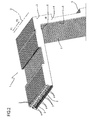
- the numeral 1 denotes a covering device.
- the covering device 1 is used to protect fixed or moving parts of machine tools or automatic machines from external contaminating agents.
- the covering device 1 comprises a plurality of mounting frames 2 arranged parallel to each other along a direction of extension labelled D in the drawings.
- the direction of extension D is defined by the directions of feed along which the covering device 1 can move, as indicated by the arrow F.
- the covering device 1 has the shape of an L.
- the covering device 1 might have the shape of a U.
- the shape of the covering device 1 is defined by the shape of the mounting frames 2.
- the mounting frames 2 have an L-shaped main cross section.
- the mounting frames 2 are connected to each other by pleated, bellows elements 3.
- each bellows element 3 is interposed between two mounting frames 2.
- the mounting frames 2 are movable towards and away from each other from a least extended configuration, where the covering device 1 is closed, to a most extended configuration where it is open, and vice versa.
- the bellows elements 3 can be extended or contracted as the mounting frames 2 are moved away from and towards each other in the directions indicated by the arrows F1 and F2, respectively.
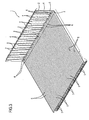
- Each mounting frame 2 comprises at least two side panels 5 and a corner element 6 interposed between the two side panels 5.
- the side panels 5 are positioned at an angle to each other and define a common, uncovered corner region which is covered by the corner element 6.
- the side panels 5 are at right angles to each other to define the L-shaped structure.
- Each mounting frame 2 comprises a vertical panel 4 connected to the side panels 5 and to the corner element 6.
- the vertical panels 4 of the mounting frames 6 are parallel to each other along the direction of extension D of the device 1.
- Each bellows element 3 is fixed to the vertical panels 4 of two consecutive mounting frames 2 between which the selfsame bellows element 3 is interposed.
- the bellows elements 3 come into contact with the side panels 5 and with the corner element 6 of one of the two mounting frames 2 between which they are interposed.
- the corner element 6 comprises a first and a second panel 8 and 9 at an angle to each other.
- the first and second panels 8 and 9 are at right angles to each other, defining an opening angle of 90°.
- the opening angle between the first and the second panel 8 and 9 is substantially the same as the angle defined by the side panels 5.
- each mounting frame 2 The side panels 5 of each mounting frame 2 are positioned at least partly on top of a respective portion of the corner element 6 associated therewith.
- a first side panel 5a is positioned on top of a portion of the outside surface 10 of the first panel 8 and a second side panel 5b is positioned on top of a portion of the outside surface 11 of the second panel 9 of the corner element 6.
- outside surface 10 and 11 of the first and the second panel 8 and 9 is meant the surface that comes at least partly into contact with the bellows element 3.
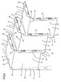
- each corner element 6 At least partly overlaps the consecutive corner element 6.
- first and the second panel 8 and 9 of one corner element 6 is positioned at least partly on top of the respective first and second panel 8 and 9 of the consecutive corner element 6.
- each corner element 6 slides on the consecutive corner element 6 from a first to a second end position along a direction parallel to the feed direction D.
- each mounting frame 2 overlap at least partly the respective side panels 5 of the adjacent mounting frame 2.
- each side panel 5 slides along a direction parallel to the feed direction D from a first to a second end position on the respective side panel 5 which it overlaps.
- the sliding of the side panels 5 and corner element 6 of two consecutive mounting frames 2 makes it possible to reduce considerably the size of the covering device 1 when it is in its closed configuration.
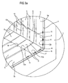
- the first and the second panel 8 and 9 of each corner element 6 comprises a respective first and second scraper fin 13 and 14.
- the first and the second scraper fin 13 and 14 are inclined at an angle to the first and the second panel 8 and 9.
- first and the second scraper fin 13 and 14 are inclined at a respective angle relative to the inclination of the first and the second panel 8 and 9.
- the first and the second fin 13 and 14 are inclined at respective bend lines 20.
- the first and the second scraper fin 13 and 14 are inclined at a defined angle ⁇ .
- the angle ⁇ is 165°.
- the angle ⁇ may be a value in the range between 135° and 175°, including the limits.
- the inclination of the first and second fins 13 and 14 of each corner element 6 is constant along the extension of the respective first and second panels 8 and 9.
- the first and the second scraper fin 13 and 14 are directed outwards relative to the outside surface of the corner element 6 in such a way as to scrape the inside surfaces 12a and 12b of the first and the second panel 8 and 9 of the consecutive corner element 6.
- the first and the second scraper fin 13 and 14 prevent external contaminating agents from finding their way between two consecutive corner elements 6.
- inside surface 12a and 12b of the first and the second panel 8 and 9 is meant the surface which is not visible from the outside of the covering device 1 because it is directed towards the machine parts to be covered.
- the first and second panels 8 and 9 of each corner element 6 are contiguous along a bend line 15 defining a cusp 16 having two free ends 17 and 18 opposite one another.
- the first and the second fin 13 and 14 of each corner element 6 converge towards the same end 17 of the cusp 16.
- the first and the second fin 13 and 14 of each corner element 6 are substantially triangular in shape, each with a respective base 19 and sides 20 and 21 connecting the base 19 to the same end 17 of the cusp 16.
- Each bend line 20 of the first and second fins 13 and 14 coincides with one of the two sides of the selfsame fins.
- each first and second fin 13 and 14 diverge from the respective base 19, which defines their maximum distance apart, and converge on the common vertex 17, coinciding with one of the two ends of the cusp 16.
- each first and second fin 13 and 14 define an opening angle ⁇ of 6°.
- the angle ⁇ may be a value in the range between 3° and 12°, including the limits.
- the shape of the scraper fins 13 and 14 prevents jamming of two consecutive corner elements 6 during the sliding of one corner element 6 relative to the other since the first and the second scraper fin 13 and 14 converge on the second vertex 17 of the cusp 16, allowing each corner element 6 to slide within the bend line 15 of the consecutive corner element 6.
- each corner element 6 can be connected directly to the vertical panel 4 of the respective mounting frame 2 by a rigid connection, as illustrated in particular in Figure 3a .
- first and second panels 8 and 9 of each corner element 6 are connected to the respective mounting frame 2 by respective side flanges 22.
- the side flanges 22 are at right angles to the first and second panels 8 and 9 and parallel to the vertical panel 4 of the respective mounting frame 2.
- a rigid connection between the corner element 6 and the respective mounting frame 2 makes it easier to assemble the covering device 1 and reduces its routine maintenance costs.
Landscapes
- Engineering & Computer Science (AREA)
- General Engineering & Computer Science (AREA)
- Mechanical Engineering (AREA)
- Extrusion Moulding Of Plastics Or The Like (AREA)
- Seal Device For Vehicle (AREA)
- Glass Compositions (AREA)
- Mirrors, Picture Frames, Photograph Stands, And Related Fastening Devices (AREA)
- Casings For Electric Apparatus (AREA)
Claims (9)
- Dispositif de recouvrement comprenant une pluralité de supports de montage (2) positionnés parallèlement les uns aux autres et se rapprochant ou s'éloignant les uns des autres le long d'une direction (D) de mouvement alternatif ;
chaque support de montage (2) comprenant au moins deux panneaux latéraux de protection (5) positionnés suivant un angle l'un par rapport à l'autre ;
un élément d'angle (6) interposé entre les deux panneaux latéraux (5) dans une zone d'angle commune (7) à partir d'une extrémité du dispositif de recouvrement (1) ; chaque élément d'angle (6) chevauchant au moins en partie l'élément d'angle consécutif (6) ; lors du mouvement alternatif des supports de montage (2), chaque élément d'angle (6) pouvant coulisser, le long d'une direction parallèle à la direction d'alimentation (D), sur l'élément d'angle (6) lui étant consécutif et qu'il chevauche ;
l'élément d'angle (6) comprenant un premier et un second panneau (8, 9) suivant un angle l'un par rapport à l'autre ;
les premier et second panneaux (8, 9) de chaque élément d'angle (6) étant contigus le long d'une ligne de pliage (15) définissant une cuspide (16) ayant deux extrémités libres (17, 18) opposées l'une à l'autre ;
le premier et le second panneau (8, 9) de chaque élément d'angle (6) comprenant une première et une seconde ailette de raclage respectives (13, 14) ;
le dispositif de recouvrement étant caractérisé en ce que la première et la seconde ailette (13, 14) de chaque élément d'angle (6) convergent vers la même extrémité (17) de la cuspide (16). - Dispositif selon la revendication 1, caractérisé en ce que les panneaux latéraux (5) de chaque support de montage (2) sont positionnés au moins partiellement au-dessus d'une partie respective de l'élément d'angle respectif (6) ; un premier panneau latéral (5a) est positionné au-dessus d'une partie de la surface extérieure (10) du premier panneau (8) et un second panneau latéral (5b) est positionné au-dessus d'une partie de la surface extérieure (11) du second panneau (9) de l'élément d'angle (6).
- Dispositif selon la revendication 2, caractérisé en ce que les panneaux latéraux (5) de chaque support de montage (2) chevauchent au moins partiellement les panneaux latéraux respectifs (5) de l'élément d'angle consécutif (6) ; lors du mouvement alternatif des supports de montage (2), chaque panneau latéral (5) pouvant coulisser, le long d'une direction parallèle à la direction d'alimentation (D), sur le panneau latéral correspondant (5).
- Dispositif selon l'une quelconque des revendications de 1 à 3, caractérisé en ce que chaque élément d'angle (6) comprend un premier et un second panneau (8, 9) réciproquement orthogonaux et contigus le long d'une ligne de pliage (15) définissant une cuspide (16) ayant deux extrémités libres (17, 18) ; le premier et le second panneau (8, 9) de chaque élément d'angle (6) comprenant une première et une seconde ailette de raclage respectives (13, 14) inclinées réciproquement selon un angle défini (α) et convergeant au niveau de la même extrémité (17) de la cuspide (16) ; les première et seconde ailettes (13, 14) de chaque élément d'angle (6) étant orientées à l'extérieur et raclant la surface intérieure de l'élément d'angle (6) lui étant consécutif.
- Dispositif selon la revendication 4, caractérisé en ce que les première et seconde ailettes (13, 14) de chaque élément d'angle (6) possèdent la forme d'un triangle, chacune ayant une base (19) et des côtés respectifs (20, 21) qui divergent vers la base respective (19) et convergent vers la même extrémité (17) de la cuspide (16).
- Dispositif selon les revendications 4 ou 5, caractérisé en ce que l'inclinaison des première et seconde ailettes (13, 14) de chaque élément d'angle (6) est constante le long de l'extension des premier et second panneaux respectifs (8, 9).
- Dispositif selon l'une quelconque des revendications de 4 à 6, caractérisé en ce que l'angle d'inclinaison (α) des première et seconde ailettes de raclage (13, 14) est compris entre 135° et 175°, en incluant les extrémités.
- Dispositif selon l'une quelconque des revendications de 4 à 7, caractérisé en ce que chaque support de montage (2) comprend un panneau vertical (4) ; chaque élément d'angle (6) étant relié directement au panneau vertical (4) du support de montage respectif (2) par un raccordement rigide.
- Dispositif selon la revendication 8, caractérisé en ce que les premier et second panneaux (8, 9) de chaque élément d'angle (6) sont reliés au support de montage respectif (2) par des rebords latéraux respectifs (22) orthogonaux par rapport aux premier et second panneaux (8, 9) et parallèles au panneau vertical (4) du support (2) lui-même.
Applications Claiming Priority (1)
| Application Number | Priority Date | Filing Date | Title |
|---|---|---|---|
| IT000492A ITBO20120492A1 (it) | 2012-09-18 | 2012-09-18 | Dispositivo di copertura |
Publications (2)
| Publication Number | Publication Date |
|---|---|
| EP2708321A1 EP2708321A1 (fr) | 2014-03-19 |
| EP2708321B1 true EP2708321B1 (fr) | 2015-03-04 |
Family
ID=47146464
Family Applications (1)
| Application Number | Title | Priority Date | Filing Date |
|---|---|---|---|
| EP20130184813 Not-in-force EP2708321B1 (fr) | 2012-09-18 | 2013-09-17 | Dispositif de recouvrement |
Country Status (3)
| Country | Link |
|---|---|
| EP (1) | EP2708321B1 (fr) |
| ES (1) | ES2537753T3 (fr) |
| IT (1) | ITBO20120492A1 (fr) |
Families Citing this family (1)
| Publication number | Priority date | Publication date | Assignee | Title |
|---|---|---|---|---|
| CN107363624A (zh) * | 2016-05-11 | 2017-11-21 | 中国科学院沈阳科学仪器股份有限公司 | 铰链同步式伸缩防护罩 |
Family Cites Families (5)
| Publication number | Priority date | Publication date | Assignee | Title |
|---|---|---|---|---|
| DE3928379A1 (de) * | 1989-08-28 | 1991-03-21 | Kabelschlepp Gmbh | Teleskopabdeckung |
| DE202004004685U1 (de) * | 2004-03-25 | 2004-06-17 | Möller Werke GmbH | Abdeckvorrichtung für Gleit- und Führungsbahnen von Maschinen |
| DE102005031539A1 (de) * | 2005-07-06 | 2007-01-11 | Möller Werke GmbH | Abdeckvorrichtung |
| DE202005014596U1 (de) * | 2005-09-14 | 2005-12-08 | Arno Arnold Gmbh | Schutzabdeckung |
| DE202007008389U1 (de) * | 2007-06-12 | 2007-08-23 | Arno Arnold Gmbh | Transversal abgewinkelte Schutzabdeckung |
-
2012
- 2012-09-18 IT IT000492A patent/ITBO20120492A1/it unknown
-
2013
- 2013-09-17 ES ES13184813.7T patent/ES2537753T3/es active Active
- 2013-09-17 EP EP20130184813 patent/EP2708321B1/fr not_active Not-in-force
Also Published As
| Publication number | Publication date |
|---|---|
| ITBO20120492A1 (it) | 2014-03-19 |
| EP2708321A1 (fr) | 2014-03-19 |
| ES2537753T3 (es) | 2015-06-11 |
Similar Documents
| Publication | Publication Date | Title |
|---|---|---|
| CN105829008B (zh) | 用于分离加工板状工件的机器 | |
| US20070230836A1 (en) | Cover for machine tool guide structures | |
| RU2013142235A (ru) | Пластина рафинера с постепенно изменяющейся геометрией | |
| EP2708321B1 (fr) | Dispositif de recouvrement | |
| EP1382416B1 (fr) | Dispositif couvrant de protection pour machines ou installations | |
| KR101300976B1 (ko) | 수평방식의 u자형 볼트 벤딩머신 | |
| EP2708318A1 (fr) | Dispositif de recouvrement protecteur pour machine ou équipement | |
| US20180304424A1 (en) | Machining center | |
| JP5725618B2 (ja) | 伸縮保護装置及びこの伸縮保護装置の設置構造 | |
| CA2887074A1 (fr) | Joint lateral pour filtre a bascule | |
| US6394719B1 (en) | Protective cover for a working part of a machine that moves in a linear direction | |
| EP2483033B1 (fr) | Capot protecteur plat doté de deux degrés de liberté pour machines-outils | |
| EP3175951B1 (fr) | Couvercle de protection | |
| KR101659684B1 (ko) | 슬라이딩 방식의 덮개를 구비한 롤 포밍 장치 | |
| EP3031574B1 (fr) | Dispositif de protection | |
| US6481313B1 (en) | Protective cover attachable to a working part which is mobile in at least one plane | |
| US6082716A (en) | Shock absorber device for telescopic protection devices | |
| EP3925731B1 (fr) | Housse de protection pour machines ou appareils | |
| JP6782480B2 (ja) | 工作機械の隔壁構造 | |
| CN105952792B (zh) | 一种便于维护的轨道导向装置 | |
| JP5172520B2 (ja) | 伸縮目地カバー装置 | |
| US9931686B2 (en) | Protective cover for vibrating compactor and manufacturing method thereof | |
| KR20140032106A (ko) | 보호필름 커팅용 지그 | |
| CN105952791B (zh) | 一种防超程的轨道导向组件 | |
| CN105750932B (zh) | 一种可提高密封性的轨道导向装置 |
Legal Events
| Date | Code | Title | Description |
|---|---|---|---|
| PUAI | Public reference made under article 153(3) epc to a published international application that has entered the european phase |
Free format text: ORIGINAL CODE: 0009012 |
|
| AK | Designated contracting states |
Kind code of ref document: A1 Designated state(s): AL AT BE BG CH CY CZ DE DK EE ES FI FR GB GR HR HU IE IS IT LI LT LU LV MC MK MT NL NO PL PT RO RS SE SI SK SM TR |
|
| AX | Request for extension of the european patent |
Extension state: BA ME |
|
| 17P | Request for examination filed |
Effective date: 20140902 |
|
| GRAP | Despatch of communication of intention to grant a patent |
Free format text: ORIGINAL CODE: EPIDOSNIGR1 |
|
| RBV | Designated contracting states (corrected) |
Designated state(s): AL AT BE BG CH CY CZ DE DK EE ES FI FR GB GR HR HU IE IS IT LI LT LU LV MC MK MT NL NO PL PT RO RS SE SI SK SM TR |
|
| RIC1 | Information provided on ipc code assigned before grant |
Ipc: B23Q 11/08 20060101AFI20140923BHEP Ipc: F16P 1/02 20060101ALI20140923BHEP |
|
| INTG | Intention to grant announced |
Effective date: 20141008 |
|
| GRAS | Grant fee paid |
Free format text: ORIGINAL CODE: EPIDOSNIGR3 |
|
| GRAA | (expected) grant |
Free format text: ORIGINAL CODE: 0009210 |
|
| AK | Designated contracting states |
Kind code of ref document: B1 Designated state(s): AL AT BE BG CH CY CZ DE DK EE ES FI FR GB GR HR HU IE IS IT LI LT LU LV MC MK MT NL NO PL PT RO RS SE SI SK SM TR |
|
| REG | Reference to a national code |
Ref country code: GB Ref legal event code: FG4D |
|
| REG | Reference to a national code |
Ref country code: CH Ref legal event code: EP |
|
| REG | Reference to a national code |
Ref country code: IE Ref legal event code: FG4D |
|
| REG | Reference to a national code |
Ref country code: AT Ref legal event code: REF Ref document number: 713414 Country of ref document: AT Kind code of ref document: T Effective date: 20150415 |
|
| REG | Reference to a national code |
Ref country code: DE Ref legal event code: R096 Ref document number: 602013001105 Country of ref document: DE Effective date: 20150416 |
|
| REG | Reference to a national code |
Ref country code: ES Ref legal event code: FG2A Ref document number: 2537753 Country of ref document: ES Kind code of ref document: T3 Effective date: 20150611 |
|
| REG | Reference to a national code |
Ref country code: AT Ref legal event code: MK05 Ref document number: 713414 Country of ref document: AT Kind code of ref document: T Effective date: 20150304 Ref country code: NL Ref legal event code: VDEP Effective date: 20150304 |
|
| PG25 | Lapsed in a contracting state [announced via postgrant information from national office to epo] |
Ref country code: SE Free format text: LAPSE BECAUSE OF FAILURE TO SUBMIT A TRANSLATION OF THE DESCRIPTION OR TO PAY THE FEE WITHIN THE PRESCRIBED TIME-LIMIT Effective date: 20150304 Ref country code: LT Free format text: LAPSE BECAUSE OF FAILURE TO SUBMIT A TRANSLATION OF THE DESCRIPTION OR TO PAY THE FEE WITHIN THE PRESCRIBED TIME-LIMIT Effective date: 20150304 Ref country code: NO Free format text: LAPSE BECAUSE OF FAILURE TO SUBMIT A TRANSLATION OF THE DESCRIPTION OR TO PAY THE FEE WITHIN THE PRESCRIBED TIME-LIMIT Effective date: 20150604 Ref country code: FI Free format text: LAPSE BECAUSE OF FAILURE TO SUBMIT A TRANSLATION OF THE DESCRIPTION OR TO PAY THE FEE WITHIN THE PRESCRIBED TIME-LIMIT Effective date: 20150304 Ref country code: HR Free format text: LAPSE BECAUSE OF FAILURE TO SUBMIT A TRANSLATION OF THE DESCRIPTION OR TO PAY THE FEE WITHIN THE PRESCRIBED TIME-LIMIT Effective date: 20150304 |
|
| REG | Reference to a national code |
Ref country code: LT Ref legal event code: MG4D |
|
| PG25 | Lapsed in a contracting state [announced via postgrant information from national office to epo] |
Ref country code: LV Free format text: LAPSE BECAUSE OF FAILURE TO SUBMIT A TRANSLATION OF THE DESCRIPTION OR TO PAY THE FEE WITHIN THE PRESCRIBED TIME-LIMIT Effective date: 20150304 Ref country code: AT Free format text: LAPSE BECAUSE OF FAILURE TO SUBMIT A TRANSLATION OF THE DESCRIPTION OR TO PAY THE FEE WITHIN THE PRESCRIBED TIME-LIMIT Effective date: 20150304 Ref country code: GR Free format text: LAPSE BECAUSE OF FAILURE TO SUBMIT A TRANSLATION OF THE DESCRIPTION OR TO PAY THE FEE WITHIN THE PRESCRIBED TIME-LIMIT Effective date: 20150605 Ref country code: RS Free format text: LAPSE BECAUSE OF FAILURE TO SUBMIT A TRANSLATION OF THE DESCRIPTION OR TO PAY THE FEE WITHIN THE PRESCRIBED TIME-LIMIT Effective date: 20150304 |
|
| PG25 | Lapsed in a contracting state [announced via postgrant information from national office to epo] |
Ref country code: NL Free format text: LAPSE BECAUSE OF FAILURE TO SUBMIT A TRANSLATION OF THE DESCRIPTION OR TO PAY THE FEE WITHIN THE PRESCRIBED TIME-LIMIT Effective date: 20150304 |
|
| PG25 | Lapsed in a contracting state [announced via postgrant information from national office to epo] |
Ref country code: PT Free format text: LAPSE BECAUSE OF FAILURE TO SUBMIT A TRANSLATION OF THE DESCRIPTION OR TO PAY THE FEE WITHIN THE PRESCRIBED TIME-LIMIT Effective date: 20150706 Ref country code: EE Free format text: LAPSE BECAUSE OF FAILURE TO SUBMIT A TRANSLATION OF THE DESCRIPTION OR TO PAY THE FEE WITHIN THE PRESCRIBED TIME-LIMIT Effective date: 20150304 Ref country code: CZ Free format text: LAPSE BECAUSE OF FAILURE TO SUBMIT A TRANSLATION OF THE DESCRIPTION OR TO PAY THE FEE WITHIN THE PRESCRIBED TIME-LIMIT Effective date: 20150304 Ref country code: SK Free format text: LAPSE BECAUSE OF FAILURE TO SUBMIT A TRANSLATION OF THE DESCRIPTION OR TO PAY THE FEE WITHIN THE PRESCRIBED TIME-LIMIT Effective date: 20150304 Ref country code: RO Free format text: LAPSE BECAUSE OF FAILURE TO SUBMIT A TRANSLATION OF THE DESCRIPTION OR TO PAY THE FEE WITHIN THE PRESCRIBED TIME-LIMIT Effective date: 20150304 |
|
| PG25 | Lapsed in a contracting state [announced via postgrant information from national office to epo] |
Ref country code: PL Free format text: LAPSE BECAUSE OF FAILURE TO SUBMIT A TRANSLATION OF THE DESCRIPTION OR TO PAY THE FEE WITHIN THE PRESCRIBED TIME-LIMIT Effective date: 20150304 Ref country code: IS Free format text: LAPSE BECAUSE OF FAILURE TO SUBMIT A TRANSLATION OF THE DESCRIPTION OR TO PAY THE FEE WITHIN THE PRESCRIBED TIME-LIMIT Effective date: 20150704 |
|
| REG | Reference to a national code |
Ref country code: DE Ref legal event code: R097 Ref document number: 602013001105 Country of ref document: DE |
|
| PLBE | No opposition filed within time limit |
Free format text: ORIGINAL CODE: 0009261 |
|
| STAA | Information on the status of an ep patent application or granted ep patent |
Free format text: STATUS: NO OPPOSITION FILED WITHIN TIME LIMIT |
|
| PG25 | Lapsed in a contracting state [announced via postgrant information from national office to epo] |
Ref country code: DK Free format text: LAPSE BECAUSE OF FAILURE TO SUBMIT A TRANSLATION OF THE DESCRIPTION OR TO PAY THE FEE WITHIN THE PRESCRIBED TIME-LIMIT Effective date: 20150304 |
|
| 26N | No opposition filed |
Effective date: 20151207 |
|
| PG25 | Lapsed in a contracting state [announced via postgrant information from national office to epo] |
Ref country code: SI Free format text: LAPSE BECAUSE OF FAILURE TO SUBMIT A TRANSLATION OF THE DESCRIPTION OR TO PAY THE FEE WITHIN THE PRESCRIBED TIME-LIMIT Effective date: 20150304 |
|
| PG25 | Lapsed in a contracting state [announced via postgrant information from national office to epo] |
Ref country code: MC Free format text: LAPSE BECAUSE OF FAILURE TO SUBMIT A TRANSLATION OF THE DESCRIPTION OR TO PAY THE FEE WITHIN THE PRESCRIBED TIME-LIMIT Effective date: 20150304 Ref country code: LU Free format text: LAPSE BECAUSE OF FAILURE TO SUBMIT A TRANSLATION OF THE DESCRIPTION OR TO PAY THE FEE WITHIN THE PRESCRIBED TIME-LIMIT Effective date: 20150917 |
|
| REG | Reference to a national code |
Ref country code: IE Ref legal event code: MM4A |
|
| REG | Reference to a national code |
Ref country code: FR Ref legal event code: ST Effective date: 20160531 |
|
| PG25 | Lapsed in a contracting state [announced via postgrant information from national office to epo] |
Ref country code: IE Free format text: LAPSE BECAUSE OF NON-PAYMENT OF DUE FEES Effective date: 20150917 |
|
| PG25 | Lapsed in a contracting state [announced via postgrant information from national office to epo] |
Ref country code: BE Free format text: LAPSE BECAUSE OF FAILURE TO SUBMIT A TRANSLATION OF THE DESCRIPTION OR TO PAY THE FEE WITHIN THE PRESCRIBED TIME-LIMIT Effective date: 20150304 Ref country code: FR Free format text: LAPSE BECAUSE OF NON-PAYMENT OF DUE FEES Effective date: 20150930 |
|
| PG25 | Lapsed in a contracting state [announced via postgrant information from national office to epo] |
Ref country code: MT Free format text: LAPSE BECAUSE OF FAILURE TO SUBMIT A TRANSLATION OF THE DESCRIPTION OR TO PAY THE FEE WITHIN THE PRESCRIBED TIME-LIMIT Effective date: 20150304 |
|
| REG | Reference to a national code |
Ref country code: CH Ref legal event code: PL |
|
| PG25 | Lapsed in a contracting state [announced via postgrant information from national office to epo] |
Ref country code: HU Free format text: LAPSE BECAUSE OF FAILURE TO SUBMIT A TRANSLATION OF THE DESCRIPTION OR TO PAY THE FEE WITHIN THE PRESCRIBED TIME-LIMIT; INVALID AB INITIO Effective date: 20130917 Ref country code: BG Free format text: LAPSE BECAUSE OF FAILURE TO SUBMIT A TRANSLATION OF THE DESCRIPTION OR TO PAY THE FEE WITHIN THE PRESCRIBED TIME-LIMIT Effective date: 20150304 |
|
| PG25 | Lapsed in a contracting state [announced via postgrant information from national office to epo] |
Ref country code: CY Free format text: LAPSE BECAUSE OF FAILURE TO SUBMIT A TRANSLATION OF THE DESCRIPTION OR TO PAY THE FEE WITHIN THE PRESCRIBED TIME-LIMIT Effective date: 20150304 |
|
| PG25 | Lapsed in a contracting state [announced via postgrant information from national office to epo] |
Ref country code: LI Free format text: LAPSE BECAUSE OF NON-PAYMENT OF DUE FEES Effective date: 20160930 Ref country code: CH Free format text: LAPSE BECAUSE OF NON-PAYMENT OF DUE FEES Effective date: 20160930 |
|
| GBPC | Gb: european patent ceased through non-payment of renewal fee |
Effective date: 20170917 |
|
| PG25 | Lapsed in a contracting state [announced via postgrant information from national office to epo] |
Ref country code: SM Free format text: LAPSE BECAUSE OF FAILURE TO SUBMIT A TRANSLATION OF THE DESCRIPTION OR TO PAY THE FEE WITHIN THE PRESCRIBED TIME-LIMIT Effective date: 20150304 |
|
| PG25 | Lapsed in a contracting state [announced via postgrant information from national office to epo] |
Ref country code: TR Free format text: LAPSE BECAUSE OF FAILURE TO SUBMIT A TRANSLATION OF THE DESCRIPTION OR TO PAY THE FEE WITHIN THE PRESCRIBED TIME-LIMIT Effective date: 20150304 Ref country code: MK Free format text: LAPSE BECAUSE OF FAILURE TO SUBMIT A TRANSLATION OF THE DESCRIPTION OR TO PAY THE FEE WITHIN THE PRESCRIBED TIME-LIMIT Effective date: 20150304 |
|
| PG25 | Lapsed in a contracting state [announced via postgrant information from national office to epo] |
Ref country code: GB Free format text: LAPSE BECAUSE OF NON-PAYMENT OF DUE FEES Effective date: 20170917 |
|
| PG25 | Lapsed in a contracting state [announced via postgrant information from national office to epo] |
Ref country code: AL Free format text: LAPSE BECAUSE OF FAILURE TO SUBMIT A TRANSLATION OF THE DESCRIPTION OR TO PAY THE FEE WITHIN THE PRESCRIBED TIME-LIMIT Effective date: 20150304 |
|
| PGFP | Annual fee paid to national office [announced via postgrant information from national office to epo] |
Ref country code: DE Payment date: 20200928 Year of fee payment: 8 |
|
| PGFP | Annual fee paid to national office [announced via postgrant information from national office to epo] |
Ref country code: IT Payment date: 20200922 Year of fee payment: 8 |
|
| PGFP | Annual fee paid to national office [announced via postgrant information from national office to epo] |
Ref country code: ES Payment date: 20201020 Year of fee payment: 8 |
|
| REG | Reference to a national code |
Ref country code: DE Ref legal event code: R119 Ref document number: 602013001105 Country of ref document: DE |
|
| PG25 | Lapsed in a contracting state [announced via postgrant information from national office to epo] |
Ref country code: DE Free format text: LAPSE BECAUSE OF NON-PAYMENT OF DUE FEES Effective date: 20220401 |
|
| PG25 | Lapsed in a contracting state [announced via postgrant information from national office to epo] |
Ref country code: IT Free format text: LAPSE BECAUSE OF NON-PAYMENT OF DUE FEES Effective date: 20210917 |
|
| REG | Reference to a national code |
Ref country code: ES Ref legal event code: FD2A Effective date: 20221125 |
|
| PG25 | Lapsed in a contracting state [announced via postgrant information from national office to epo] |
Ref country code: ES Free format text: LAPSE BECAUSE OF NON-PAYMENT OF DUE FEES Effective date: 20210918 |