EP2708321B1 - Covering device - Google Patents
Covering device Download PDFInfo
- Publication number
- EP2708321B1 EP2708321B1 EP20130184813 EP13184813A EP2708321B1 EP 2708321 B1 EP2708321 B1 EP 2708321B1 EP 20130184813 EP20130184813 EP 20130184813 EP 13184813 A EP13184813 A EP 13184813A EP 2708321 B1 EP2708321 B1 EP 2708321B1
- Authority
- EP
- European Patent Office
- Prior art keywords
- corner element
- panel
- panels
- corner
- mounting frame
- Prior art date
- Legal status (The legal status is an assumption and is not a legal conclusion. Google has not performed a legal analysis and makes no representation as to the accuracy of the status listed.)
- Not-in-force
Links
- 238000007790 scraping Methods 0.000 claims 1
- 238000012423 maintenance Methods 0.000 description 1
- 239000002184 metal Substances 0.000 description 1
- 238000000034 method Methods 0.000 description 1
- 238000007493 shaping process Methods 0.000 description 1
- 239000002699 waste material Substances 0.000 description 1
Images


Classifications
-
- B—PERFORMING OPERATIONS; TRANSPORTING
- B23—MACHINE TOOLS; METAL-WORKING NOT OTHERWISE PROVIDED FOR
- B23Q—DETAILS, COMPONENTS, OR ACCESSORIES FOR MACHINE TOOLS, e.g. ARRANGEMENTS FOR COPYING OR CONTROLLING; MACHINE TOOLS IN GENERAL CHARACTERISED BY THE CONSTRUCTION OF PARTICULAR DETAILS OR COMPONENTS; COMBINATIONS OR ASSOCIATIONS OF METAL-WORKING MACHINES, NOT DIRECTED TO A PARTICULAR RESULT
- B23Q11/00—Accessories fitted to machine tools for keeping tools or parts of the machine in good working condition or for cooling work; Safety devices specially combined with or arranged in, or specially adapted for use in connection with, machine tools
- B23Q11/08—Protective coverings for parts of machine tools; Splash guards
- B23Q11/0825—Relatively slidable coverings, e.g. telescopic
-
- F—MECHANICAL ENGINEERING; LIGHTING; HEATING; WEAPONS; BLASTING
- F16—ENGINEERING ELEMENTS AND UNITS; GENERAL MEASURES FOR PRODUCING AND MAINTAINING EFFECTIVE FUNCTIONING OF MACHINES OR INSTALLATIONS; THERMAL INSULATION IN GENERAL
- F16P—SAFETY DEVICES IN GENERAL; SAFETY DEVICES FOR PRESSES
- F16P1/00—Safety devices independent of the control and operation of any machine
- F16P1/02—Fixed screens or hoods
-
- F—MECHANICAL ENGINEERING; LIGHTING; HEATING; WEAPONS; BLASTING
- F16—ENGINEERING ELEMENTS AND UNITS; GENERAL MEASURES FOR PRODUCING AND MAINTAINING EFFECTIVE FUNCTIONING OF MACHINES OR INSTALLATIONS; THERMAL INSULATION IN GENERAL
- F16P—SAFETY DEVICES IN GENERAL; SAFETY DEVICES FOR PRESSES
- F16P3/00—Safety devices acting in conjunction with the control or operation of a machine; Control arrangements requiring the simultaneous use of two or more parts of the body
- F16P3/02—Screens or other safety members moving in synchronism with members which move to and fro
Definitions
- This invention relates to a covering device for machinery or equipment, according to the preamble of claim 1, as known from DE-A-10 2005 031 539 . More specifically, the covering devices referred to can be advantageously applied in several industrial sectors, such as, for example, the sector of machine tools and automatic machines, whose fixed or moving parts, such as slideways and working tools, are protected by the covering devices.
- These covering devices comprise a set of parallel covering elements movable towards and away from each other from a least extended configuration to a most extended configuration and vice versa.
- each covering element comprises a mounting frame, usually fixed, relative to which the covering elements move when they are extended or retracted.
- Some mounting frames are preferably L-shaped and have side and corner covering panels fixed to them.
- the side covering panels are usually made of metal because they have to be resistant to chippings, swarf and other machine process waste. As a result, they have a substantially rigid, inflexible structure.
- the main problem affecting the smooth operation of the covers of this kind is that the individual side covering panels, which also substantially have the shape of an L defined by two perpendicular elements, must have a gap between them at the corners of the frame to avoid creating excessive mechanical stresses at the corners which would lead to uncontrolled friction preventing the covers themselves from sliding relative to each other.
- each corner zone was given a rounded form either by shaping each panel or by adding a third portion, interposed between the two elements making up the L, in such a way as to create stretches which were inclined relative to the corner.
- One major disadvantage is due to the relatively large size of the covering device in the least extended configuration because the minimum size is given by the sum of the lengths of the corner covering elements.
- This invention has for an aim to provide a covering device which overcomes the above mentioned disadvantages.
- the numeral 1 denotes a covering device.
- the covering device 1 is used to protect fixed or moving parts of machine tools or automatic machines from external contaminating agents.
- the covering device 1 comprises a plurality of mounting frames 2 arranged parallel to each other along a direction of extension labelled D in the drawings.
- the direction of extension D is defined by the directions of feed along which the covering device 1 can move, as indicated by the arrow F.
- the covering device 1 has the shape of an L.
- the covering device 1 might have the shape of a U.
- the shape of the covering device 1 is defined by the shape of the mounting frames 2.
- the mounting frames 2 have an L-shaped main cross section.
- the mounting frames 2 are connected to each other by pleated, bellows elements 3.
- each bellows element 3 is interposed between two mounting frames 2.
- the mounting frames 2 are movable towards and away from each other from a least extended configuration, where the covering device 1 is closed, to a most extended configuration where it is open, and vice versa.
- the bellows elements 3 can be extended or contracted as the mounting frames 2 are moved away from and towards each other in the directions indicated by the arrows F1 and F2, respectively.
- Each mounting frame 2 comprises at least two side panels 5 and a corner element 6 interposed between the two side panels 5.
- the side panels 5 are positioned at an angle to each other and define a common, uncovered corner region which is covered by the corner element 6.
- the side panels 5 are at right angles to each other to define the L-shaped structure.
- Each mounting frame 2 comprises a vertical panel 4 connected to the side panels 5 and to the corner element 6.
- the vertical panels 4 of the mounting frames 6 are parallel to each other along the direction of extension D of the device 1.
- Each bellows element 3 is fixed to the vertical panels 4 of two consecutive mounting frames 2 between which the selfsame bellows element 3 is interposed.
- the bellows elements 3 come into contact with the side panels 5 and with the corner element 6 of one of the two mounting frames 2 between which they are interposed.
- the corner element 6 comprises a first and a second panel 8 and 9 at an angle to each other.
- the first and second panels 8 and 9 are at right angles to each other, defining an opening angle of 90°.
- the opening angle between the first and the second panel 8 and 9 is substantially the same as the angle defined by the side panels 5.
- each mounting frame 2 The side panels 5 of each mounting frame 2 are positioned at least partly on top of a respective portion of the corner element 6 associated therewith.
- a first side panel 5a is positioned on top of a portion of the outside surface 10 of the first panel 8 and a second side panel 5b is positioned on top of a portion of the outside surface 11 of the second panel 9 of the corner element 6.
- outside surface 10 and 11 of the first and the second panel 8 and 9 is meant the surface that comes at least partly into contact with the bellows element 3.
- each corner element 6 At least partly overlaps the consecutive corner element 6.
- first and the second panel 8 and 9 of one corner element 6 is positioned at least partly on top of the respective first and second panel 8 and 9 of the consecutive corner element 6.
- each corner element 6 slides on the consecutive corner element 6 from a first to a second end position along a direction parallel to the feed direction D.
- each mounting frame 2 overlap at least partly the respective side panels 5 of the adjacent mounting frame 2.
- each side panel 5 slides along a direction parallel to the feed direction D from a first to a second end position on the respective side panel 5 which it overlaps.
- the sliding of the side panels 5 and corner element 6 of two consecutive mounting frames 2 makes it possible to reduce considerably the size of the covering device 1 when it is in its closed configuration.
- the first and the second panel 8 and 9 of each corner element 6 comprises a respective first and second scraper fin 13 and 14.
- the first and the second scraper fin 13 and 14 are inclined at an angle to the first and the second panel 8 and 9.
- first and the second scraper fin 13 and 14 are inclined at a respective angle relative to the inclination of the first and the second panel 8 and 9.
- the first and the second fin 13 and 14 are inclined at respective bend lines 20.
- the first and the second scraper fin 13 and 14 are inclined at a defined angle ⁇ .
- the angle ⁇ is 165°.
- the angle ⁇ may be a value in the range between 135° and 175°, including the limits.
- the inclination of the first and second fins 13 and 14 of each corner element 6 is constant along the extension of the respective first and second panels 8 and 9.
- the first and the second scraper fin 13 and 14 are directed outwards relative to the outside surface of the corner element 6 in such a way as to scrape the inside surfaces 12a and 12b of the first and the second panel 8 and 9 of the consecutive corner element 6.
- the first and the second scraper fin 13 and 14 prevent external contaminating agents from finding their way between two consecutive corner elements 6.
- inside surface 12a and 12b of the first and the second panel 8 and 9 is meant the surface which is not visible from the outside of the covering device 1 because it is directed towards the machine parts to be covered.
- the first and second panels 8 and 9 of each corner element 6 are contiguous along a bend line 15 defining a cusp 16 having two free ends 17 and 18 opposite one another.
- the first and the second fin 13 and 14 of each corner element 6 converge towards the same end 17 of the cusp 16.
- the first and the second fin 13 and 14 of each corner element 6 are substantially triangular in shape, each with a respective base 19 and sides 20 and 21 connecting the base 19 to the same end 17 of the cusp 16.
- Each bend line 20 of the first and second fins 13 and 14 coincides with one of the two sides of the selfsame fins.
- each first and second fin 13 and 14 diverge from the respective base 19, which defines their maximum distance apart, and converge on the common vertex 17, coinciding with one of the two ends of the cusp 16.
- each first and second fin 13 and 14 define an opening angle ⁇ of 6°.
- the angle ⁇ may be a value in the range between 3° and 12°, including the limits.
- the shape of the scraper fins 13 and 14 prevents jamming of two consecutive corner elements 6 during the sliding of one corner element 6 relative to the other since the first and the second scraper fin 13 and 14 converge on the second vertex 17 of the cusp 16, allowing each corner element 6 to slide within the bend line 15 of the consecutive corner element 6.
- each corner element 6 can be connected directly to the vertical panel 4 of the respective mounting frame 2 by a rigid connection, as illustrated in particular in Figure 3a .
- first and second panels 8 and 9 of each corner element 6 are connected to the respective mounting frame 2 by respective side flanges 22.
- the side flanges 22 are at right angles to the first and second panels 8 and 9 and parallel to the vertical panel 4 of the respective mounting frame 2.
- a rigid connection between the corner element 6 and the respective mounting frame 2 makes it easier to assemble the covering device 1 and reduces its routine maintenance costs.
Landscapes
- Engineering & Computer Science (AREA)
- General Engineering & Computer Science (AREA)
- Mechanical Engineering (AREA)
- Extrusion Moulding Of Plastics Or The Like (AREA)
- Seal Device For Vehicle (AREA)
- Glass Compositions (AREA)
- Mirrors, Picture Frames, Photograph Stands, And Related Fastening Devices (AREA)
- Casings For Electric Apparatus (AREA)
Description
- This invention relates to a covering device for machinery or equipment, according to the preamble of
claim 1, as known fromDE-A-10 2005 031 539 . More specifically, the covering devices referred to can be advantageously applied in several industrial sectors, such as, for example, the sector of machine tools and automatic machines, whose fixed or moving parts, such as slideways and working tools, are protected by the covering devices. - These covering devices comprise a set of parallel covering elements movable towards and away from each other from a least extended configuration to a most extended configuration and vice versa.
- At one end of it, each covering element comprises a mounting frame, usually fixed, relative to which the covering elements move when they are extended or retracted. Some mounting frames are preferably L-shaped and have side and corner covering panels fixed to them.
- The side covering panels are usually made of metal because they have to be resistant to chippings, swarf and other machine process waste. As a result, they have a substantially rigid, inflexible structure. The main problem affecting the smooth operation of the covers of this kind is that the individual side covering panels, which also substantially have the shape of an L defined by two perpendicular elements, must have a gap between them at the corners of the frame to avoid creating excessive mechanical stresses at the corners which would lead to uncontrolled friction preventing the covers themselves from sliding relative to each other.
- This feature, although it solves the problem of friction, means that the corner zones of the cover are left unprotected.
- An attempt to overcome this problem was made by eliminating the bend from each panel at the corner zones, which formed a substantially sharp edge between the two elements making up the L. More specifically, each corner zone was given a rounded form either by shaping each panel or by adding a third portion, interposed between the two elements making up the L, in such a way as to create stretches which were inclined relative to the corner.
- Covering devices of this kind, too, however, are not free of disadvantages.
- One major disadvantage is due to the relatively large size of the covering device in the least extended configuration because the minimum size is given by the sum of the lengths of the corner covering elements. Are known from the art coverage devices as described and shown, respectively, in documents
US5156195 ,DE102005031539 ,DE202005014596 . - This invention has for an aim to provide a covering device which overcomes the above mentioned disadvantages.
- The technical purpose and aims specified are achieved by a device having the features set out in
independent claim 1. - Further features and advantages of the invention are more apparent from the non-limiting description which follows of a preferred embodiment of a covering device as illustrated in the accompanying drawings, in which:
-
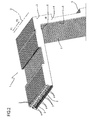
Figure 1 is a first perspective view of the covering device according to the invention; -
Figure 2 shows a scaled-up view of a detail fromFigure 1 ; -
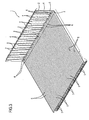
Figure 3 is a second perspective view of the covering device according to the invention; -
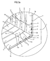
Figure 3a shows a scaled-up view of a detail fromFigure 3 ; -
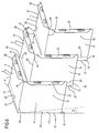
Figure 4 shows a scaled-up exploded view, with some parts cut away in order to better illustrate others, of a detail fromFigure 3 ; -
Figure 5 shows some details fromFigure 4 in a further perspective view. - With reference to
Figures 1 to 3 , thenumeral 1 denotes a covering device. - Generally speaking, the covering
device 1 is used to protect fixed or moving parts of machine tools or automatic machines from external contaminating agents. - The covering
device 1 comprises a plurality ofmounting frames 2 arranged parallel to each other along a direction of extension labelled D in the drawings. - The direction of extension D is defined by the directions of feed along which the covering
device 1 can move, as indicated by the arrow F. In the embodiment illustrated, thecovering device 1 has the shape of an L. - Alternatively, the covering
device 1 might have the shape of a U. - The shape of the covering
device 1 is defined by the shape of themounting frames 2. - Thus, at right angles to the feed direction D, the
mounting frames 2 have an L-shaped main cross section. - Preferably, the
mounting frames 2 are connected to each other by pleated,bellows elements 3. - More specifically, each
bellows element 3 is interposed between twomounting frames 2. - The
mounting frames 2 are movable towards and away from each other from a least extended configuration, where the coveringdevice 1 is closed, to a most extended configuration where it is open, and vice versa. - The
bellows elements 3 can be extended or contracted as themounting frames 2 are moved away from and towards each other in the directions indicated by the arrows F1 and F2, respectively. - Each
mounting frame 2 comprises at least twoside panels 5 and acorner element 6 interposed between the twoside panels 5. - The
side panels 5 are positioned at an angle to each other and define a common, uncovered corner region which is covered by thecorner element 6. - More specifically, the
side panels 5 are at right angles to each other to define the L-shaped structure. - Each
mounting frame 2 comprises avertical panel 4 connected to theside panels 5 and to thecorner element 6. - The
vertical panels 4 of themounting frames 6 are parallel to each other along the direction of extension D of thedevice 1. - Each
bellows element 3 is fixed to thevertical panels 4 of twoconsecutive mounting frames 2 between which theselfsame bellows element 3 is interposed. - That way, the
bellows elements 3 come into contact with theside panels 5 and with thecorner element 6 of one of the twomounting frames 2 between which they are interposed. - The
corner element 6 comprises a first and asecond panel - Preferably, the first and
second panels - It should be noted that the opening angle between the first and the
second panel side panels 5. - The
side panels 5 of eachmounting frame 2 are positioned at least partly on top of a respective portion of thecorner element 6 associated therewith. - More precisely, a
first side panel 5a is positioned on top of a portion of theoutside surface 10 of thefirst panel 8 and asecond side panel 5b is positioned on top of a portion of theoutside surface 11 of thesecond panel 9 of thecorner element 6. - By
outside surface second panel bellows element 3. - Starting from one end of the covering
device 1, eachcorner element 6 at least partly overlaps theconsecutive corner element 6. - With reference in particular to
Figures 3a ,4 and 5 , the first and thesecond panel corner element 6 is positioned at least partly on top of the respective first andsecond panel consecutive corner element 6. - That way, during the reciprocating movement of the
mounting frames 2 towards and away from each other, eachcorner element 6 slides on theconsecutive corner element 6 from a first to a second end position along a direction parallel to the feed direction D. - The
side panels 5 of eachmounting frame 2 overlap at least partly therespective side panels 5 of theadjacent mounting frame 2. - During the reciprocating movement of the
mounting frames 2 towards and away from each other, eachside panel 5 slides along a direction parallel to the feed direction D from a first to a second end position on therespective side panel 5 which it overlaps. - Advantageously, the sliding of the
side panels 5 andcorner element 6 of twoconsecutive mounting frames 2 makes it possible to reduce considerably the size of thecovering device 1 when it is in its closed configuration. - The first and the
second panel corner element 6 comprises a respective first andsecond scraper fin - The first and the
second scraper fin second panel - In other words, the first and the
second scraper fin second panel - The first and the
second fin respective bend lines 20. - The first and the
second scraper fin - Preferably, the angle α is 165°.
- The angle α may be a value in the range between 135° and 175°, including the limits.
- The inclination of the first and
second fins corner element 6 is constant along the extension of the respective first andsecond panels - The first and the
second scraper fin corner element 6 in such a way as to scrape theinside surfaces second panel consecutive corner element 6. Advantageously, the first and thesecond scraper fin consecutive corner elements 6. - By
inside surface second panel device 1 because it is directed towards the machine parts to be covered. - The first and
second panels corner element 6 are contiguous along abend line 15 defining acusp 16 having twofree ends - The first and the
second fin corner element 6 converge towards thesame end 17 of thecusp 16. - The first and the
second fin corner element 6 are substantially triangular in shape, each with arespective base 19 andsides same end 17 of thecusp 16. - Each
bend line 20 of the first andsecond fins - The
sides second fin respective base 19, which defines their maximum distance apart, and converge on thecommon vertex 17, coinciding with one of the two ends of thecusp 16. - The
sides second fin - The angle β may be a value in the range between 3° and 12°, including the limits.
- Advantageously, the shape of the
scraper fins consecutive corner elements 6 during the sliding of onecorner element 6 relative to the other since the first and thesecond scraper fin second vertex 17 of thecusp 16, allowing eachcorner element 6 to slide within thebend line 15 of theconsecutive corner element 6. - That means each
corner element 6 can be connected directly to thevertical panel 4 of therespective mounting frame 2 by a rigid connection, as illustrated in particular inFigure 3a . - More specifically, the first and
second panels corner element 6 are connected to therespective mounting frame 2 byrespective side flanges 22. - The side flanges 22 are at right angles to the first and
second panels vertical panel 4 of therespective mounting frame 2. - Advantageously, a rigid connection between the
corner element 6 and therespective mounting frame 2 makes it easier to assemble thecovering device 1 and reduces its routine maintenance costs. - The invention described above is susceptible of industrial application and it may be modified and adapted in several ways without thereby departing from the scope of the inventive concept. Moreover, all the details of the invention may be substituted for technically equivalent elements.
Claims (9)
- A covering device comprising a plurality of mounting frames (2) positioned parallel to each other and being mobile towards and away from each other along a direction (D) of reciprocating movement;
each mounting frame (2) comprising at least two side guard panels (5) positioned at an angle to each other; a corner element (6) interposed between the two side panels (5) in a common corner region (7) starting from one end of the covering device (1); each corner element (6) overlaps at least partly the consecutive corner element (6); during the reciprocating movement of the mounting frames (2), each corner element (6) being slidable, along a direction parallel to the feed direction (D), on the corner element (6) which is consecutive to it and which it overlaps;
the corner element (6) comprising a first and a second panel (8, 9) at an angle to each other;
the first and second panels (8, 9) of each corner element (6) being contiguous along a bend line (15) defining a cusp (16) having two free ends (17,18) opposite one another;
the first and the second panel (8, 9) of each corner element (6) comprising a respective first and second scraper fin (13, 14);
covering device being characterised in that
the first and the second fin (13, 14) of each corner element (6) converge towards the same end (17) of the cusp (16). - The device according to claim 1, characterized in that the side panels (5) of each mounting frame (2) are positioned at least partly on top of a respective portion of the respective corner element (6); a first side panel (5a) is positioned on top of a portion of the outside surface (10) of the first panel (8) and a second side panel (5b) is positioned on top of a portion of the outside surface (11) of the second panel (9) of the corner element (6).
- The device according to claim 2, characterized in that the side panels (5) of each mounting frame (2) overlap at least partly the respective side panels (5) of the consecutive corner element (6); during the reciprocating movement of the mounting frames (2), each side panel (5) being slidable, along a direction parallel to the feed direction (D), on the respective side panel (5).
- The device according to any of the claims from 1 to 3, characterized in that each corner element (6) comprises a first and a second panel (8, 9) at right angles to one another and contiguous along a bend line (15) defining a cusp (16) having two free ends (17, 18); the first and the second panel (8, 9) of each corner element (6) comprising a respective first and second scraper fin (13, 14) inclined at a defined angle (α) to each other and converging at the same end (17) of the cusp (16); the first and second fins (13, 14) of each corner element (6) being directed outwards and scraping the inside surface of the corner element (6) consecutive to it.
- The device according to claim 4, characterized in that the first and second fins (13, 14) of each corner element (6) have the shape of a triangle, each having a base (19) and respective sides (20, 21) which diverge towards the respective base (19) and converge towards the same end (17) of the cusp (16).
- The device according to claim 4 or 5, characterized in that the inclination of the first and second fins (13, 14) of each corner element (6) is constant along the extension of the respective first and second panels (8, 9).
- The device according to any of the claims from 4 to 6, characterized in that the inclination angle (α) of the first and second scraper fins (13, 14) is within the range 135° to 175°, including the ends.
- The device according to any of the claims from 4 to 7, characterized in that each mounting frame (2) comprises a vertical panel (4); each corner element (6) being connected directly to the vertical panel (4) of the respective mounting frame (2) by a rigid connection.
- The device according to claim 8, characterized in that the first and second panels (8, 9) of each corner element (6) are connected to the respective mounting frame (2) by respective side flanges (22) at right angles to the first and second panels (8, 9) and parallel to the vertical panel (4) of the frame (2) itself.
Applications Claiming Priority (1)
| Application Number | Priority Date | Filing Date | Title |
|---|---|---|---|
| IT000492A ITBO20120492A1 (en) | 2012-09-18 | 2012-09-18 | COVERING DEVICE |
Publications (2)
| Publication Number | Publication Date |
|---|---|
| EP2708321A1 EP2708321A1 (en) | 2014-03-19 |
| EP2708321B1 true EP2708321B1 (en) | 2015-03-04 |
Family
ID=47146464
Family Applications (1)
| Application Number | Title | Priority Date | Filing Date |
|---|---|---|---|
| EP20130184813 Not-in-force EP2708321B1 (en) | 2012-09-18 | 2013-09-17 | Covering device |
Country Status (3)
| Country | Link |
|---|---|
| EP (1) | EP2708321B1 (en) |
| ES (1) | ES2537753T3 (en) |
| IT (1) | ITBO20120492A1 (en) |
Families Citing this family (1)
| Publication number | Priority date | Publication date | Assignee | Title |
|---|---|---|---|---|
| CN107363624A (en) * | 2016-05-11 | 2017-11-21 | 中国科学院沈阳科学仪器股份有限公司 | Hinge synchronization formula Telescopic protective cover |
Family Cites Families (5)
| Publication number | Priority date | Publication date | Assignee | Title |
|---|---|---|---|---|
| DE3928379A1 (en) * | 1989-08-28 | 1991-03-21 | Kabelschlepp Gmbh | TELESCOPE COVER |
| DE202004004685U1 (en) * | 2004-03-25 | 2004-06-17 | Möller Werke GmbH | Cover mechanism for guide tracks of machine tools, especially milling machines, consists of two lamellae arrangements, with lamellae of second arrangement arranged at a distance parallel to lamellae projections |
| DE102005031539A1 (en) * | 2005-07-06 | 2007-01-11 | Möller Werke GmbH | covering |
| DE202005014596U1 (en) * | 2005-09-14 | 2005-12-08 | Arno Arnold Gmbh | Cover for moving machine part, comprising multitude of metal segments movable joined with folded areas |
| DE202007008389U1 (en) * | 2007-06-12 | 2007-08-23 | Arno Arnold Gmbh | Protective cover e.g. L-shaped protective cover, has protective cover segments with two lamellae independent of each other, where guiding surfaces of segments mutually overlap lamellae at transversal bending of segments |
-
2012
- 2012-09-18 IT IT000492A patent/ITBO20120492A1/en unknown
-
2013
- 2013-09-17 ES ES13184813.7T patent/ES2537753T3/en active Active
- 2013-09-17 EP EP20130184813 patent/EP2708321B1/en not_active Not-in-force
Also Published As
| Publication number | Publication date |
|---|---|
| ITBO20120492A1 (en) | 2014-03-19 |
| EP2708321A1 (en) | 2014-03-19 |
| ES2537753T3 (en) | 2015-06-11 |
Similar Documents
| Publication | Publication Date | Title |
|---|---|---|
| CN105829008B (en) | Machines for separating and machining sheet-like workpieces | |
| US20070230836A1 (en) | Cover for machine tool guide structures | |
| RU2013142235A (en) | REFINER PLATE WITH A GRADUALLY CHANGING GEOMETRY | |
| EP2708321B1 (en) | Covering device | |
| EP1382416B1 (en) | A protective covering device for machinery or equipment | |
| KR101300976B1 (en) | Bending machine for u-type bolt of horizontal type | |
| EP2708318A1 (en) | Protective covering device for machinery or equipment | |
| US20180304424A1 (en) | Machining center | |
| JP5725618B2 (en) | Extension protection device and installation structure of the extension protection device | |
| CA2887074A1 (en) | Lateral sealing for flip-flow screen | |
| US6394719B1 (en) | Protective cover for a working part of a machine that moves in a linear direction | |
| EP2483033B1 (en) | A flat protective cover with two degrees of freedom for tool machines | |
| EP3175951B1 (en) | Protective cover | |
| KR101659684B1 (en) | Roll forming machine with sliding type cover | |
| EP3031574B1 (en) | Protective device | |
| US6481313B1 (en) | Protective cover attachable to a working part which is mobile in at least one plane | |
| US6082716A (en) | Shock absorber device for telescopic protection devices | |
| EP3925731B1 (en) | A protective covering device for machinery or apparatuses | |
| JP6782480B2 (en) | Machine tool bulkhead structure | |
| CN105952792B (en) | A kind of guiding device of track convenient for safeguarding | |
| JP5172520B2 (en) | Telescopic joint cover device | |
| US9931686B2 (en) | Protective cover for vibrating compactor and manufacturing method thereof | |
| KR20140032106A (en) | Protect film cutting jigue | |
| CN105952791B (en) | A kind of rail-guided component of anti-overtravel | |
| CN105750932B (en) | A kind of guiding device of track for improving sealing |
Legal Events
| Date | Code | Title | Description |
|---|---|---|---|
| PUAI | Public reference made under article 153(3) epc to a published international application that has entered the european phase |
Free format text: ORIGINAL CODE: 0009012 |
|
| AK | Designated contracting states |
Kind code of ref document: A1 Designated state(s): AL AT BE BG CH CY CZ DE DK EE ES FI FR GB GR HR HU IE IS IT LI LT LU LV MC MK MT NL NO PL PT RO RS SE SI SK SM TR |
|
| AX | Request for extension of the european patent |
Extension state: BA ME |
|
| 17P | Request for examination filed |
Effective date: 20140902 |
|
| GRAP | Despatch of communication of intention to grant a patent |
Free format text: ORIGINAL CODE: EPIDOSNIGR1 |
|
| RBV | Designated contracting states (corrected) |
Designated state(s): AL AT BE BG CH CY CZ DE DK EE ES FI FR GB GR HR HU IE IS IT LI LT LU LV MC MK MT NL NO PL PT RO RS SE SI SK SM TR |
|
| RIC1 | Information provided on ipc code assigned before grant |
Ipc: B23Q 11/08 20060101AFI20140923BHEP Ipc: F16P 1/02 20060101ALI20140923BHEP |
|
| INTG | Intention to grant announced |
Effective date: 20141008 |
|
| GRAS | Grant fee paid |
Free format text: ORIGINAL CODE: EPIDOSNIGR3 |
|
| GRAA | (expected) grant |
Free format text: ORIGINAL CODE: 0009210 |
|
| AK | Designated contracting states |
Kind code of ref document: B1 Designated state(s): AL AT BE BG CH CY CZ DE DK EE ES FI FR GB GR HR HU IE IS IT LI LT LU LV MC MK MT NL NO PL PT RO RS SE SI SK SM TR |
|
| REG | Reference to a national code |
Ref country code: GB Ref legal event code: FG4D |
|
| REG | Reference to a national code |
Ref country code: CH Ref legal event code: EP |
|
| REG | Reference to a national code |
Ref country code: IE Ref legal event code: FG4D |
|
| REG | Reference to a national code |
Ref country code: AT Ref legal event code: REF Ref document number: 713414 Country of ref document: AT Kind code of ref document: T Effective date: 20150415 |
|
| REG | Reference to a national code |
Ref country code: DE Ref legal event code: R096 Ref document number: 602013001105 Country of ref document: DE Effective date: 20150416 |
|
| REG | Reference to a national code |
Ref country code: ES Ref legal event code: FG2A Ref document number: 2537753 Country of ref document: ES Kind code of ref document: T3 Effective date: 20150611 |
|
| REG | Reference to a national code |
Ref country code: AT Ref legal event code: MK05 Ref document number: 713414 Country of ref document: AT Kind code of ref document: T Effective date: 20150304 Ref country code: NL Ref legal event code: VDEP Effective date: 20150304 |
|
| PG25 | Lapsed in a contracting state [announced via postgrant information from national office to epo] |
Ref country code: SE Free format text: LAPSE BECAUSE OF FAILURE TO SUBMIT A TRANSLATION OF THE DESCRIPTION OR TO PAY THE FEE WITHIN THE PRESCRIBED TIME-LIMIT Effective date: 20150304 Ref country code: LT Free format text: LAPSE BECAUSE OF FAILURE TO SUBMIT A TRANSLATION OF THE DESCRIPTION OR TO PAY THE FEE WITHIN THE PRESCRIBED TIME-LIMIT Effective date: 20150304 Ref country code: NO Free format text: LAPSE BECAUSE OF FAILURE TO SUBMIT A TRANSLATION OF THE DESCRIPTION OR TO PAY THE FEE WITHIN THE PRESCRIBED TIME-LIMIT Effective date: 20150604 Ref country code: FI Free format text: LAPSE BECAUSE OF FAILURE TO SUBMIT A TRANSLATION OF THE DESCRIPTION OR TO PAY THE FEE WITHIN THE PRESCRIBED TIME-LIMIT Effective date: 20150304 Ref country code: HR Free format text: LAPSE BECAUSE OF FAILURE TO SUBMIT A TRANSLATION OF THE DESCRIPTION OR TO PAY THE FEE WITHIN THE PRESCRIBED TIME-LIMIT Effective date: 20150304 |
|
| REG | Reference to a national code |
Ref country code: LT Ref legal event code: MG4D |
|
| PG25 | Lapsed in a contracting state [announced via postgrant information from national office to epo] |
Ref country code: LV Free format text: LAPSE BECAUSE OF FAILURE TO SUBMIT A TRANSLATION OF THE DESCRIPTION OR TO PAY THE FEE WITHIN THE PRESCRIBED TIME-LIMIT Effective date: 20150304 Ref country code: AT Free format text: LAPSE BECAUSE OF FAILURE TO SUBMIT A TRANSLATION OF THE DESCRIPTION OR TO PAY THE FEE WITHIN THE PRESCRIBED TIME-LIMIT Effective date: 20150304 Ref country code: GR Free format text: LAPSE BECAUSE OF FAILURE TO SUBMIT A TRANSLATION OF THE DESCRIPTION OR TO PAY THE FEE WITHIN THE PRESCRIBED TIME-LIMIT Effective date: 20150605 Ref country code: RS Free format text: LAPSE BECAUSE OF FAILURE TO SUBMIT A TRANSLATION OF THE DESCRIPTION OR TO PAY THE FEE WITHIN THE PRESCRIBED TIME-LIMIT Effective date: 20150304 |
|
| PG25 | Lapsed in a contracting state [announced via postgrant information from national office to epo] |
Ref country code: NL Free format text: LAPSE BECAUSE OF FAILURE TO SUBMIT A TRANSLATION OF THE DESCRIPTION OR TO PAY THE FEE WITHIN THE PRESCRIBED TIME-LIMIT Effective date: 20150304 |
|
| PG25 | Lapsed in a contracting state [announced via postgrant information from national office to epo] |
Ref country code: PT Free format text: LAPSE BECAUSE OF FAILURE TO SUBMIT A TRANSLATION OF THE DESCRIPTION OR TO PAY THE FEE WITHIN THE PRESCRIBED TIME-LIMIT Effective date: 20150706 Ref country code: EE Free format text: LAPSE BECAUSE OF FAILURE TO SUBMIT A TRANSLATION OF THE DESCRIPTION OR TO PAY THE FEE WITHIN THE PRESCRIBED TIME-LIMIT Effective date: 20150304 Ref country code: CZ Free format text: LAPSE BECAUSE OF FAILURE TO SUBMIT A TRANSLATION OF THE DESCRIPTION OR TO PAY THE FEE WITHIN THE PRESCRIBED TIME-LIMIT Effective date: 20150304 Ref country code: SK Free format text: LAPSE BECAUSE OF FAILURE TO SUBMIT A TRANSLATION OF THE DESCRIPTION OR TO PAY THE FEE WITHIN THE PRESCRIBED TIME-LIMIT Effective date: 20150304 Ref country code: RO Free format text: LAPSE BECAUSE OF FAILURE TO SUBMIT A TRANSLATION OF THE DESCRIPTION OR TO PAY THE FEE WITHIN THE PRESCRIBED TIME-LIMIT Effective date: 20150304 |
|
| PG25 | Lapsed in a contracting state [announced via postgrant information from national office to epo] |
Ref country code: PL Free format text: LAPSE BECAUSE OF FAILURE TO SUBMIT A TRANSLATION OF THE DESCRIPTION OR TO PAY THE FEE WITHIN THE PRESCRIBED TIME-LIMIT Effective date: 20150304 Ref country code: IS Free format text: LAPSE BECAUSE OF FAILURE TO SUBMIT A TRANSLATION OF THE DESCRIPTION OR TO PAY THE FEE WITHIN THE PRESCRIBED TIME-LIMIT Effective date: 20150704 |
|
| REG | Reference to a national code |
Ref country code: DE Ref legal event code: R097 Ref document number: 602013001105 Country of ref document: DE |
|
| PLBE | No opposition filed within time limit |
Free format text: ORIGINAL CODE: 0009261 |
|
| STAA | Information on the status of an ep patent application or granted ep patent |
Free format text: STATUS: NO OPPOSITION FILED WITHIN TIME LIMIT |
|
| PG25 | Lapsed in a contracting state [announced via postgrant information from national office to epo] |
Ref country code: DK Free format text: LAPSE BECAUSE OF FAILURE TO SUBMIT A TRANSLATION OF THE DESCRIPTION OR TO PAY THE FEE WITHIN THE PRESCRIBED TIME-LIMIT Effective date: 20150304 |
|
| 26N | No opposition filed |
Effective date: 20151207 |
|
| PG25 | Lapsed in a contracting state [announced via postgrant information from national office to epo] |
Ref country code: SI Free format text: LAPSE BECAUSE OF FAILURE TO SUBMIT A TRANSLATION OF THE DESCRIPTION OR TO PAY THE FEE WITHIN THE PRESCRIBED TIME-LIMIT Effective date: 20150304 |
|
| PG25 | Lapsed in a contracting state [announced via postgrant information from national office to epo] |
Ref country code: MC Free format text: LAPSE BECAUSE OF FAILURE TO SUBMIT A TRANSLATION OF THE DESCRIPTION OR TO PAY THE FEE WITHIN THE PRESCRIBED TIME-LIMIT Effective date: 20150304 Ref country code: LU Free format text: LAPSE BECAUSE OF FAILURE TO SUBMIT A TRANSLATION OF THE DESCRIPTION OR TO PAY THE FEE WITHIN THE PRESCRIBED TIME-LIMIT Effective date: 20150917 |
|
| REG | Reference to a national code |
Ref country code: IE Ref legal event code: MM4A |
|
| REG | Reference to a national code |
Ref country code: FR Ref legal event code: ST Effective date: 20160531 |
|
| PG25 | Lapsed in a contracting state [announced via postgrant information from national office to epo] |
Ref country code: IE Free format text: LAPSE BECAUSE OF NON-PAYMENT OF DUE FEES Effective date: 20150917 |
|
| PG25 | Lapsed in a contracting state [announced via postgrant information from national office to epo] |
Ref country code: BE Free format text: LAPSE BECAUSE OF FAILURE TO SUBMIT A TRANSLATION OF THE DESCRIPTION OR TO PAY THE FEE WITHIN THE PRESCRIBED TIME-LIMIT Effective date: 20150304 Ref country code: FR Free format text: LAPSE BECAUSE OF NON-PAYMENT OF DUE FEES Effective date: 20150930 |
|
| PG25 | Lapsed in a contracting state [announced via postgrant information from national office to epo] |
Ref country code: MT Free format text: LAPSE BECAUSE OF FAILURE TO SUBMIT A TRANSLATION OF THE DESCRIPTION OR TO PAY THE FEE WITHIN THE PRESCRIBED TIME-LIMIT Effective date: 20150304 |
|
| REG | Reference to a national code |
Ref country code: CH Ref legal event code: PL |
|
| PG25 | Lapsed in a contracting state [announced via postgrant information from national office to epo] |
Ref country code: HU Free format text: LAPSE BECAUSE OF FAILURE TO SUBMIT A TRANSLATION OF THE DESCRIPTION OR TO PAY THE FEE WITHIN THE PRESCRIBED TIME-LIMIT; INVALID AB INITIO Effective date: 20130917 Ref country code: BG Free format text: LAPSE BECAUSE OF FAILURE TO SUBMIT A TRANSLATION OF THE DESCRIPTION OR TO PAY THE FEE WITHIN THE PRESCRIBED TIME-LIMIT Effective date: 20150304 |
|
| PG25 | Lapsed in a contracting state [announced via postgrant information from national office to epo] |
Ref country code: CY Free format text: LAPSE BECAUSE OF FAILURE TO SUBMIT A TRANSLATION OF THE DESCRIPTION OR TO PAY THE FEE WITHIN THE PRESCRIBED TIME-LIMIT Effective date: 20150304 |
|
| PG25 | Lapsed in a contracting state [announced via postgrant information from national office to epo] |
Ref country code: LI Free format text: LAPSE BECAUSE OF NON-PAYMENT OF DUE FEES Effective date: 20160930 Ref country code: CH Free format text: LAPSE BECAUSE OF NON-PAYMENT OF DUE FEES Effective date: 20160930 |
|
| GBPC | Gb: european patent ceased through non-payment of renewal fee |
Effective date: 20170917 |
|
| PG25 | Lapsed in a contracting state [announced via postgrant information from national office to epo] |
Ref country code: SM Free format text: LAPSE BECAUSE OF FAILURE TO SUBMIT A TRANSLATION OF THE DESCRIPTION OR TO PAY THE FEE WITHIN THE PRESCRIBED TIME-LIMIT Effective date: 20150304 |
|
| PG25 | Lapsed in a contracting state [announced via postgrant information from national office to epo] |
Ref country code: TR Free format text: LAPSE BECAUSE OF FAILURE TO SUBMIT A TRANSLATION OF THE DESCRIPTION OR TO PAY THE FEE WITHIN THE PRESCRIBED TIME-LIMIT Effective date: 20150304 Ref country code: MK Free format text: LAPSE BECAUSE OF FAILURE TO SUBMIT A TRANSLATION OF THE DESCRIPTION OR TO PAY THE FEE WITHIN THE PRESCRIBED TIME-LIMIT Effective date: 20150304 |
|
| PG25 | Lapsed in a contracting state [announced via postgrant information from national office to epo] |
Ref country code: GB Free format text: LAPSE BECAUSE OF NON-PAYMENT OF DUE FEES Effective date: 20170917 |
|
| PG25 | Lapsed in a contracting state [announced via postgrant information from national office to epo] |
Ref country code: AL Free format text: LAPSE BECAUSE OF FAILURE TO SUBMIT A TRANSLATION OF THE DESCRIPTION OR TO PAY THE FEE WITHIN THE PRESCRIBED TIME-LIMIT Effective date: 20150304 |
|
| PGFP | Annual fee paid to national office [announced via postgrant information from national office to epo] |
Ref country code: DE Payment date: 20200928 Year of fee payment: 8 |
|
| PGFP | Annual fee paid to national office [announced via postgrant information from national office to epo] |
Ref country code: IT Payment date: 20200922 Year of fee payment: 8 |
|
| PGFP | Annual fee paid to national office [announced via postgrant information from national office to epo] |
Ref country code: ES Payment date: 20201020 Year of fee payment: 8 |
|
| REG | Reference to a national code |
Ref country code: DE Ref legal event code: R119 Ref document number: 602013001105 Country of ref document: DE |
|
| PG25 | Lapsed in a contracting state [announced via postgrant information from national office to epo] |
Ref country code: DE Free format text: LAPSE BECAUSE OF NON-PAYMENT OF DUE FEES Effective date: 20220401 |
|
| PG25 | Lapsed in a contracting state [announced via postgrant information from national office to epo] |
Ref country code: IT Free format text: LAPSE BECAUSE OF NON-PAYMENT OF DUE FEES Effective date: 20210917 |
|
| REG | Reference to a national code |
Ref country code: ES Ref legal event code: FD2A Effective date: 20221125 |
|
| PG25 | Lapsed in a contracting state [announced via postgrant information from national office to epo] |
Ref country code: ES Free format text: LAPSE BECAUSE OF NON-PAYMENT OF DUE FEES Effective date: 20210918 |