EP2706930B1 - Rückholvorrichtung mit lösbar befestigter schlinge - Google Patents
Rückholvorrichtung mit lösbar befestigter schlinge Download PDFInfo
- Publication number
- EP2706930B1 EP2706930B1 EP12786215.9A EP12786215A EP2706930B1 EP 2706930 B1 EP2706930 B1 EP 2706930B1 EP 12786215 A EP12786215 A EP 12786215A EP 2706930 B1 EP2706930 B1 EP 2706930B1
- Authority
- EP
- European Patent Office
- Prior art keywords
- loop
- shaft
- snare
- delivery conduit
- loops
- Prior art date
- Legal status (The legal status is an assumption and is not a legal conclusion. Google has not performed a legal analysis and makes no representation as to the accuracy of the status listed.)
- Not-in-force
Links
- 230000008878 coupling Effects 0.000 claims description 8
- 238000010168 coupling process Methods 0.000 claims description 8
- 238000005859 coupling reaction Methods 0.000 claims description 8
- 238000002560 therapeutic procedure Methods 0.000 description 13
- -1 polyethylene Polymers 0.000 description 5
- 239000000463 material Substances 0.000 description 3
- 230000013011 mating Effects 0.000 description 3
- 230000008859 change Effects 0.000 description 2
- 239000012634 fragment Substances 0.000 description 2
- 230000003993 interaction Effects 0.000 description 2
- 229920000139 polyethylene terephthalate Polymers 0.000 description 2
- 239000005020 polyethylene terephthalate Substances 0.000 description 2
- 229920002633 Kraton (polymer) Polymers 0.000 description 1
- 239000004677 Nylon Substances 0.000 description 1
- 239000002033 PVDF binder Substances 0.000 description 1
- 239000004698 Polyethylene Substances 0.000 description 1
- 239000004743 Polypropylene Substances 0.000 description 1
- 210000003484 anatomy Anatomy 0.000 description 1
- 230000001419 dependent effect Effects 0.000 description 1
- 239000012530 fluid Substances 0.000 description 1
- 230000007246 mechanism Effects 0.000 description 1
- 238000000034 method Methods 0.000 description 1
- 229920001778 nylon Polymers 0.000 description 1
- 210000000056 organ Anatomy 0.000 description 1
- 239000004033 plastic Substances 0.000 description 1
- 229920003023 plastic Polymers 0.000 description 1
- 239000004417 polycarbonate Substances 0.000 description 1
- 229920000515 polycarbonate Polymers 0.000 description 1
- 229920000573 polyethylene Polymers 0.000 description 1
- 229920001155 polypropylene Polymers 0.000 description 1
- 229920002635 polyurethane Polymers 0.000 description 1
- 239000004814 polyurethane Substances 0.000 description 1
- 229920000915 polyvinyl chloride Polymers 0.000 description 1
- 239000004800 polyvinyl chloride Substances 0.000 description 1
- 229920002981 polyvinylidene fluoride Polymers 0.000 description 1
- 230000008569 process Effects 0.000 description 1
- 229920003031 santoprene Polymers 0.000 description 1
Images


Classifications
-
- A—HUMAN NECESSITIES
- A61—MEDICAL OR VETERINARY SCIENCE; HYGIENE
- A61B—DIAGNOSIS; SURGERY; IDENTIFICATION
- A61B17/00—Surgical instruments, devices or methods
- A61B17/00234—Surgical instruments, devices or methods for minimally invasive surgery
-
- A—HUMAN NECESSITIES
- A61—MEDICAL OR VETERINARY SCIENCE; HYGIENE
- A61B—DIAGNOSIS; SURGERY; IDENTIFICATION
- A61B17/00—Surgical instruments, devices or methods
- A61B17/22—Implements for squeezing-off ulcers or the like on inner organs of the body; Implements for scraping-out cavities of body organs, e.g. bones; for invasive removal or destruction of calculus using mechanical vibrations; for removing obstructions in blood vessels, not otherwise provided for
- A61B17/221—Gripping devices in the form of loops or baskets for gripping calculi or similar types of obstructions
-
- A—HUMAN NECESSITIES
- A61—MEDICAL OR VETERINARY SCIENCE; HYGIENE
- A61B—DIAGNOSIS; SURGERY; IDENTIFICATION
- A61B17/00—Surgical instruments, devices or methods
- A61B17/00234—Surgical instruments, devices or methods for minimally invasive surgery
- A61B2017/00358—Snares for grasping
-
- A—HUMAN NECESSITIES
- A61—MEDICAL OR VETERINARY SCIENCE; HYGIENE
- A61B—DIAGNOSIS; SURGERY; IDENTIFICATION
- A61B17/00—Surgical instruments, devices or methods
- A61B2017/0046—Surgical instruments, devices or methods with a releasable handle; with handle and operating part separable
- A61B2017/00473—Distal part, e.g. tip or head
-
- A—HUMAN NECESSITIES
- A61—MEDICAL OR VETERINARY SCIENCE; HYGIENE
- A61B—DIAGNOSIS; SURGERY; IDENTIFICATION
- A61B17/00—Surgical instruments, devices or methods
- A61B17/22—Implements for squeezing-off ulcers or the like on inner organs of the body; Implements for scraping-out cavities of body organs, e.g. bones; for invasive removal or destruction of calculus using mechanical vibrations; for removing obstructions in blood vessels, not otherwise provided for
- A61B2017/22038—Implements for squeezing-off ulcers or the like on inner organs of the body; Implements for scraping-out cavities of body organs, e.g. bones; for invasive removal or destruction of calculus using mechanical vibrations; for removing obstructions in blood vessels, not otherwise provided for with a guide wire
- A61B2017/22039—Implements for squeezing-off ulcers or the like on inner organs of the body; Implements for scraping-out cavities of body organs, e.g. bones; for invasive removal or destruction of calculus using mechanical vibrations; for removing obstructions in blood vessels, not otherwise provided for with a guide wire eccentric
-
- A—HUMAN NECESSITIES
- A61—MEDICAL OR VETERINARY SCIENCE; HYGIENE
- A61B—DIAGNOSIS; SURGERY; IDENTIFICATION
- A61B17/00—Surgical instruments, devices or methods
- A61B17/34—Trocars; Puncturing needles
- A61B17/3417—Details of tips or shafts, e.g. grooves, expandable, bendable; Multiple coaxial sliding cannulas, e.g. for dilating
- A61B17/3421—Cannulas
- A61B2017/3445—Cannulas used as instrument channel for multiple instruments
Definitions
- the present disclosure relates generally to devices used to retrieve or manipulate items or structures located in anatomically remote locations, such as items located in body lumens. More specifically, the present disclosure relates to retrieval devices, such as snares, which may be configured with releasably coupled snare loops.
- US,5 782,839 describes a medical grasper device for grasping and manipulating a body organ.
- the grasper device comprises a flexible strap having a distal section that is deployed from a tube to form a partially closed loop, wherein a terminal end of the strap can be attached to a connection means to form a closed loop.
- the strap can be moved along and through the inside passage of the tube.
- the other end of the strap is useful as a manipulative means to deploy the loop strap section out through the distal end of the tube and to retract the loop strap section inside the tube.
- a snare device may be configured with two or more releasably coupled snare loops. Such a device may provide versatility, allowing a practitioner to select a particular snare loop based upon characteristics of the loop (such as size or shape) and the parameters of the therapy.
- the invention is defined in claim 1. Further embodiments of the invention are defined in the dependent claims.
- phrases “connected to,” “coupled to,” and “in communication with” refer to any form of interaction between two or more entities, including mechanical, electrical, magnetic, electromagnetic, fluid, and thermal interaction.
- Two components may be coupled to each other even though they are not in direct contact with each other.
- two components may be coupled to each other through an intermediate component.
- distal and proximal are given their ordinary meaning in the art. That is, the distal end of a medical device means the end of the device furthest from the practitioner during use. The proximal end refers to the opposite end, or the end nearest the practitioner during use.
- Delivery conduit refers to an artificial channel capable of establishing communication between a remote location and an external environment.
- the delivery conduit comprises the outer sheath of a snare device, which in some embodiments comprises a catheter.
- fragment means either a foreign object disposed within a body lumen or an anatomical structure within the body which requires ligation or removal.
- a "snare device” refers to a medical device with an elongate shape having at least one "snare loop.”
- a snare device may or may not include a delivery conduit or outer sheath member.
- a "snare loop” refers to a closed shape configuration of an elongate member, such as a wire.
- the term is not limited to “loops” with generally circular shapes, but includes any variety of shapes, including, for example, square loops, rectangular loops, ellipsoidal loops, trapezoidal loops, etc.
- a snare "loop” may also include “basket” type loops which are formed of multiple strands of wire or other material to form a basket-like enclosure rather than a single flat enclosed shape.
- Figure 1 is a side view of a delivery conduit 100, or catheter, having a single lumen 105.
- the lumen 105 extends the length of the delivery conduit 100 from the proximal end 104 of the delivery conduit 100 to the distal end 102 of the delivery conduit 100.
- the delivery conduit 100 and the lumen 105 may define a side wall 101 of the delivery conduit.
- the side wall 101 may be defined as the portion of the delivery conduit 100 surrounding the lumen where the outer surface of the side wall runs generally parallel to the longitudinal axis of the delivery conduit 100.
- the delivery conduit may have a distal opening 110 which allows the lumen 105 to be in communication with the environment outside the distal end 102 of the delivery conduit 100.
- the distal opening 110 may be an opening in the side wall 101 of the delivery conduit 100.
- distal opening 110 extends through the side wall 101 of the delivery conduit 100, allowing access from the lumen 105 to an area outside the delivery conduit 100.
- the distal opening 110 may constitute a removed area of from about 5% to about 48% of the circumference of the side wall 101 of the delivery conduit.
- the distal opening 110 may fall into a smaller range of values, for example from about 25% to about 48% of the circumference of the delivery conduit.
- the distal opening 110 may be in a different location on the delivery conduit 100, such as in the distal end 102 of the delivery conduit 100.
- the delivery conduit 100 may also be configured with a connector 120 to couple the delivery conduit 100 to another device.
- This connector 120 may be any type of connector known in the art, for example, a luer connector.
- the delivery conduit 100 may define an outer sheath through which medical devices (for example, guidewires or snare devices) may pass during therapy. It will be appreciated that medical devices disposed within the delivery conduit 100 may be configured to be longitudinally displaceable with respect to the delivery conduit 100 during use.
- medical devices for example, guidewires or snare devices
- the delivery conduit 100 may be made from any extrudable, medical grade plastic such as those commonly used for making catheters. Examples include but are not limited to polyurethane, polyethylene (varying densities), PET (polyethylene terephthalate), PVC, polypropylene, nylon, peba byx, ABS, Hytrel®, Santoprene®, polycarbonate, Kraton®, PES, PVDF, and FEP.
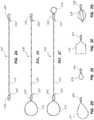
- Figure 2A is a side view of an elongate shaft 155 of a snare device 150.
- the elongate shaft 155 may have a first end 152 and a second end 154.
- the shaft may be comprised of a single, wire like member, multiple small wire members twisted or braided together, or any other configuration as known in the art.
- the shaft 155 may have an attachment portion 162, 164 at one or both ends 152, 154 of the shaft 155.
- the shaft 155 has a first attachment portion 162 at the first end 152 of the shaft 155 and a second attachment portion 164 at the second end 154 of the shaft 155.
- Figure 2B is a side view of the elongate shaft 155 of Figure 2A with a first snare loop 172 coupled to the shaft 155 at the first end 152 of the shaft 155.
- the first loop 172 is coupled to the first end 152 of the shaft 155 through use of the first attachment portion 162.
- Figure 2C is a side view of the elongate shaft 155 of Figures 2A and 2B with a first loop 172 coupled to the first end 152 as in Figure 2B , and a second loop 174 coupled to the second end 154 of the elongate shaft 155.
- the second loop 174 is coupled to the second end 154 of the shaft 155 through use of the second attachment portion 164.
- FIG. 2A-2C includes attachment portions 162, 164 at both ends 152, 154 of the elongate shaft 155.
- Figures 2D, 2E, 2F, and 2G illustrate alternate embodiments of possible snare loops 175, 176, 177, 178 that may be configured with attachment portions 165, 166, 167, 168 for use with an elongate shaft such as shaft 155 in Figures 2A, 2B, and 2C .
- the loops 175, 176, 177, 178 are illustrative and other configurations of loops (such as variations in size, shape, number of loops used together and material) may be used within the scope of this disclosure.
- a possible difference between exemplary snare loops includes loops which are of different sizes; that is, that a first loop circumscribes a greater area, by comparison, than a second loop.
- loops may be of differing shapes, for example, the loop illustrated in Figure 2F is substantially square in shape while the loops of Figures 2D and 2E are generally rounded.
- a loop may consist of multiple strands which form a "basket" type loop, such as that illustrated in Figure 2G . While the embodiment of Figure 2G is a basket formed of four strands, it will be understood that other embodiments could be formed using more or fewer strands.
- Loops such as those illustrated in Figures 2D, 2E, 2F, and 2G , may be coupled to a shaft, such as that illustrated in Figures 2A, 2B, and 2C , through use of an attachment portion. While “attachment portions” are illustrated on each of Figures 2A-2G (in some instances on the loops and on some instances on the shaft) it will be appreciated that the attachment portions illustrated, 162, 164, 165, 166, 167, 168 are meant as representations of any device or structure which may be used to couple a loop to a shaft. Thus, the illustrated "attachment portions" are representative in nature, the illustration is does not necessarily resemble any particular structure for coupling the two components.
- the "attachment portion” may consist of a structure or component initially fixed to the shaft and not to the loop, to the loop and not to the shaft, or one or more mating components may be attached to both the loop and to the shaft.
- a coupling component that may be initially fixed to only the loop is a flute and collet assembly.
- a collet may be use in connection with flutes to grip or clamp an elongate member or part.
- a loop may be configured with a flute and collet assembly fixed to a portion of the loop.
- the snare loop may then be coupled to a shaft simply by using the flute and collet assembly to clamp or grip one end of the shaft.
- the structure of the "attachment portion" is fixed to the loop prior to coupling the loop to the shaft.
- the flute and collet assembly could be fixed to the shaft and used to grip an elongate portion of the loop.
- the attachment portion may have components that are initially fixed to both the loop and the shaft.
- the shaft may be fixed to a component which includes threads and the loop fixed to a component with mating threads.
- the shaft and the loop could thus be coupled by engaging the two threaded components.
- either the loop or the shaft could be fixed to a component with either external or internal threads.
- any attachment mechanism or component known in the art may be used to attach a loop to a shaft, as described herein.
- clamps, chucks, collets, flutes, threads, interference fits (including tapered components and components with mating shoulders and flanges), pins, clips, retaining rings, or barbed connectors may all be used to couple a loop to a shaft.
- a variety of connectors used in other mechanical arts can also be adapted for use with a snare loop and shaft, for example, connectors used in connecting pneumatic hoses, hydraulic lines, or electrical wires may be so adapted.
- the attachment portion will be configured such that a loop may be coupled and/or decoupled by a medical practitioner directly. In some instances this will include situations where the practitioner may couple or decouple a loop as part of the therapeutic procedure. In differing embodiments, tools may or may not be required to couple and/or decouple a loop from a shaft.
- the attachment portion may be configured such that, once a loop is coupled to a snare shaft, it cannot be decoupled. In other embodiments, the attachment portion may be configured such that a first loop may be coupled to the shaft, decoupled, and a second loop coupled to the shaft in the place of the first loop.
- “releasably coupleable” refers to a configuration where a loop is configured to be decoupleable from a shaft after it has been coupled, including embodiments where a practitioner may decouple the loop from the shaft. Further, in certain embodiments, any number of loops could be coupled and decoupled to the same attachment portion of a shaft.
- the attachment portion may be configured such that, while a loop may be coupled or decoupled from the shaft, the loop may not be decoupled remotely.
- decoupling may require direct input from a practitioner and configured such that the loop will not readily become accidentally decoupled during use.
- the attachment member can be utilized to provide versatility and adaptability during therapy.
- the attachment member may be configured such that a practitioner may directly couple and decouple loops from a snare device shaft. Thus, a practitioner may be able to select one or more particular loops for use in a particular therapy, thus "customizing" the snare device for the particular therapy and patient.
- a practitioner may begin a therapeutic procedure by first positioning a delivery conduit within the body of a patient. The practitioner may then determine an appropriate snare loop for the necessary therapy (based on the size or shape of the loop, the material from which the loop is formed, and so on). The practitioner may then couple the selected loop to an end of a shaft which initially has no loops (such as the shaft illustrated in Figure 2A ). After coupling this first loop to a first end of the shaft, the practitioner may place the snare shaft and loop within a lumen of the delivery conduit in order to conduct the therapy.
- the practitioner may desire to change loops during the course of the therapy. For instance, the practitioner may discover, after attempting therapy with the first loop, that a different type of loop would be preferable. In another instance, a first stage of the therapy may be best suited for a first type of loop and the second stage best suited for a second type of loop.
- the practitioner may withdraw the shaft from the delivery conduit and couple a second snare loop to the shaft. In some instances, this will be accomplished by first decoupling the first loop and then coupling the second loop to the first end of the shaft. In other instances, the practitioner may couple the second loop to a second end of the shaft, allowing the first loop to remain coupled to the first end of the shaft. If the use of additional loops is desirable, the practitioner could decouple one or more of the first or second loops in order to accommodate further loops. This process may be repeated as necessary to complete the therapy.
- Figures 3A and 3B are side views of another embodiment of a snare device which can, in certain respects, resemble components of the snare devices described in connection with Figures 1, 1A , and 2A-2G above. It will be appreciated that all the illustrated embodiments have analogous features. Accordingly, like features are designated with like reference numerals, with the leading digits incremented to "2.” (For instance, the delivery conduit or catheter is designated “100" in Figure 1 and an analogous delivery conduit or catheter is designated as "200" in Figure 3A .) Relevant disclosure set forth above regarding similarly identified features thus may not be repeated hereafter.
- FIGS 3A and 3B are side views of a snare device in use.
- the snare device may include a delivery conduit 200 or catheter configured to access an anatomically remote region of the body.
- the delivery conduit may have a proximal end 202, a distal end 204, and a snare lumen 205 disposed within the conduit between the proximal and distal ends.
- the snare lumen 215 has an opening 210 near the distal end 204 of the delivery conduit 200.
- the elongate shaft 255 of a snare may be disposed within the snare lumen 205. As illustrated in Figure 3A , the snare may be deployed through the opening 210 of the snare lumen.
- a first snare loop 274 is shown coupled to the first end 254 of the elongate shaft 255 by use of an attachment portion 264.
- the illustrated embodiment also shows the first snare loop 274 being used to surround (in Figure 3A ) and capture (in Figure 3B ) a fragment 50.
- FIG. 3A and 3B also includes a guidewire 217 disposed within the delivery conduit 200 in a guidewire lumen 215.
- a guidewire may be utilized to aid in positioning the delivery conduit within the body of a patient.
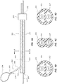
- Figure 4A is a side view of another embodiment of a snare device. Like the snare device of Figures 3A and 3B , the snare device of Figure 4A also includes a guidewire 317 disposed within a guidewire lumen 315.
- the illustrated delivery conduit 300 has two lumens; it will be appreciated that the current disclosure is relevant to devices with a single lumen (as in Figures 1 and 1A ), two lumens (as in Figures 3A-4D ), or devices with any number of lumens.
- Figures 4B, 4C, and 4D illustrate exemplary cross sectional profiles of the two lumen delivery conduit 300 of Figure 4A , taken through lines X-X.
- the delivery conduit 300 may have a circular cross section as in Figures 4B and 4D or a "figure 8" as in Figure 4C .
- each of the lumens may be circular in cross section, semi-circular, or any other cross sectional shape.
- both the snare lumen 305 and the guidewire lumen 315 have semi-circular cross sections while both lumens 305, 315 have circular cross sections in the embodiment of Figure 4C .
- one lumen may be semi-circular while the other is circular. Any combination of these or other cross sectional shapes known in the art is within the scope of this disclosure.
Landscapes
- Health & Medical Sciences (AREA)
- Surgery (AREA)
- Life Sciences & Earth Sciences (AREA)
- Heart & Thoracic Surgery (AREA)
- Nuclear Medicine, Radiotherapy & Molecular Imaging (AREA)
- Engineering & Computer Science (AREA)
- Biomedical Technology (AREA)
- Medical Informatics (AREA)
- Molecular Biology (AREA)
- Animal Behavior & Ethology (AREA)
- General Health & Medical Sciences (AREA)
- Public Health (AREA)
- Veterinary Medicine (AREA)
- Vascular Medicine (AREA)
- Orthopedic Medicine & Surgery (AREA)
- Surgical Instruments (AREA)
Claims (10)
- Schlingen-Baugruppe (150, 250, 350), umfassend:einen länglichen Schaft (155, 255, 355), der ein erstes Ende (152, 254) und ein zweites Ende aufweist (154, 252);eine erste Schlaufe (172, 274), die mit einem ersten Befestigungsabschnitt (162, 165, 168, 274) verbunden ist, welcher dazu ausgebildet ist, die erste Schlaufe (172, 274) mit dem ersten Ende (152, 254) des Schafts (155, 255, 355) zu koppeln; und eine zweite Schlaufe (174), die mit einem zweiten Befestigungsabschnitt (164, 165, 168) verbunden ist, welcher dazu ausgebildet ist, die zweite Schlaufe (174) mit dem zweiten Ende (154) des Schafts (155, 255, 355) zu koppeln;dadurch gekennzeichnet, dass die ersten und zweiten Schlaufen (172, 274, 174) jeweils unabhängig voneinander selektiv am Schaft (155, 255, 355) anbringbar sind durch einen medizinisch Praktizierenden.
- Schlingen-Baugruppe (150, 250, 350) nach Anspruch 1, wobei die erste Schlaufe (172, 274) oder die zweite Schlaufe (174) durch Gewinde mit dem Schaft (155, 255, 355) koppelbar ist.
- Schlingen-Baugruppe (150, 250, 350) nach Anspruch 1, wobei die erste Schlaufe (172, 274) oder die zweite Schlaufe (174) durch eine Welle- und Nabe-Baugruppe mit dem Schaft koppelbar ist.
- Schlingen-Baugruppe (150, 250, 350) nach Anspruch 1, wobei die erste Schlaufe (172, 274) oder die zweite Schlaufe (174) derart ausgebildet ist, dass sie nicht aus der Ferne entkoppelt werden kann.
- Schlingen-Baugruppe (150, 250, 350) nach Anspruch 1, wobei wenigstens eine der ersten Schlaufe (172, 274) oder zweiten Schlaufe (174) eine Korbschlinge (178) umfasst.
- Schlingen-Baugruppe (150, 250, 350) nach Anspruch 1, wobei die erste Schlaufe (172, 274) einen größeren Bereich umschreibt als die zweite Schlaufe (174).
- Schlingen-Baugruppe (150, 250, 350) nach Anspruch 1, wobei die erste Schlaufe (172, 274) eine andere Form hat als die zweite Schlaufe (174).
- Schlingen-Baugruppe (150, 250, 350) nach Anspruch 1, weiter umfassend eine längliche, äußere Hülle (100, 200, 300), die proximale und distale Enden (104, 202; 102, 204) aufweist und ein erstes Lumen (105, 205, 305), das innerhalb der äußeren Hülle (100, 200, 300) zwischen den proximalen und distalen Enden (104, 202, 102, 204) der äußeren Hülle (100, 200, 300) angeordnet ist, wobei das erste Lumen (105, 205, 305) dazu ausgebildet ist, den länglichen Schaft (155, 255, 355) aufzunehmen.
- Schlingen-Baugruppe (150, 250, 350) nach Anspruch 1, wobei die zweite Schlaufe zur Kopplung mit dem ersten Ende des Schafts ausgebildet ist.
- Schlingen-Baugruppe (150, 250, 350) nach Anspruch 1, ferner umfassend einen länglichen Schaft (100, 200, 300).
Applications Claiming Priority (2)
| Application Number | Priority Date | Filing Date | Title |
|---|---|---|---|
| US13/106,995 US9039713B2 (en) | 2011-05-13 | 2011-05-13 | Releasably attached snare loop retrieval device and method of using the same |
| PCT/US2012/036144 WO2012158350A1 (en) | 2011-05-13 | 2012-05-02 | Releasably attached snare loop retrieval device and method of using the same |
Publications (3)
| Publication Number | Publication Date |
|---|---|
| EP2706930A1 EP2706930A1 (de) | 2014-03-19 |
| EP2706930A4 EP2706930A4 (de) | 2015-07-08 |
| EP2706930B1 true EP2706930B1 (de) | 2018-04-04 |
Family
ID=47142365
Family Applications (1)
| Application Number | Title | Priority Date | Filing Date |
|---|---|---|---|
| EP12786215.9A Not-in-force EP2706930B1 (de) | 2011-05-13 | 2012-05-02 | Rückholvorrichtung mit lösbar befestigter schlinge |
Country Status (3)
| Country | Link |
|---|---|
| US (1) | US9039713B2 (de) |
| EP (1) | EP2706930B1 (de) |
| WO (1) | WO2012158350A1 (de) |
Families Citing this family (57)
| Publication number | Priority date | Publication date | Assignee | Title |
|---|---|---|---|---|
| DE102007043830A1 (de) | 2007-09-13 | 2009-04-02 | Lozonschi, Lucian, Madison | Herzklappenstent |
| ES2870080T3 (es) | 2009-12-08 | 2021-10-26 | Avalon Medical Ltd | Dispositivo y sistema para reemplazo de válvula mitral transcatéter |
| EP2661288B1 (de) | 2011-01-04 | 2020-04-01 | Merit Medical Systems, Inc. | Schlinge mit variabler schleife |
| EP3403616B1 (de) | 2011-08-11 | 2022-05-11 | Tendyne Holdings, Inc. | Verbesserungen für prothesenklappen und damit zusammenhängende erfindungen |
| US9827092B2 (en) | 2011-12-16 | 2017-11-28 | Tendyne Holdings, Inc. | Tethers for prosthetic mitral valve |
| US10213187B1 (en) | 2012-01-25 | 2019-02-26 | Mubin I. Syed | Method and apparatus for percutaneous superficial temporal artery access for carotid artery stenting |
| WO2014022124A1 (en) | 2012-07-28 | 2014-02-06 | Tendyne Holdings, Inc. | Improved multi-component designs for heart valve retrieval device, sealing structures and stent assembly |
| WO2014021905A1 (en) | 2012-07-30 | 2014-02-06 | Tendyne Holdings, Inc. | Improved delivery systems and methods for transcatheter prosthetic valves |
| ES2610992T3 (es) * | 2012-11-20 | 2017-05-04 | Innovheart S.R.L. | Dispositivo para desplegar un sistema de alambres guías dentro de una cámara cardíaca para implantar una válvula cardíaca protésica |
| DK2922500T3 (en) * | 2012-11-20 | 2017-02-06 | Innovheart S R L | PROCESSING PROCEDURES FOR HEALTHCARD REPLACEMENT |
| ITBO20120636A1 (it) | 2012-11-20 | 2014-05-21 | Ht Consultant Di Giovanni Righini | Sistema protesico sostitutivo per valvola cardiaca |
| US10639179B2 (en) | 2012-11-21 | 2020-05-05 | Ram Medical Innovations, Llc | System for the intravascular placement of a medical device |
| EP2948075B1 (de) * | 2013-01-23 | 2020-07-15 | Boston Scientific Scimed, Inc. | Chirurgische schlingenvorrichtung |
| US11224510B2 (en) | 2013-04-02 | 2022-01-18 | Tendyne Holdings, Inc. | Prosthetic heart valve and systems and methods for delivering the same |
| US10463489B2 (en) | 2013-04-02 | 2019-11-05 | Tendyne Holdings, Inc. | Prosthetic heart valve and systems and methods for delivering the same |
| US10478293B2 (en) | 2013-04-04 | 2019-11-19 | Tendyne Holdings, Inc. | Retrieval and repositioning system for prosthetic heart valve |
| US9610159B2 (en) | 2013-05-30 | 2017-04-04 | Tendyne Holdings, Inc. | Structural members for prosthetic mitral valves |
| WO2014205400A1 (en) * | 2013-06-21 | 2014-12-24 | Boston Scientific Scimed, Inc. | Resection devices and related methods of deployment |
| AU2014302505B2 (en) | 2013-06-25 | 2019-11-28 | Tendyne Holdings, Inc. | Thrombus management and structural compliance features for prosthetic heart valves |
| JP6465883B2 (ja) | 2013-08-01 | 2019-02-06 | テンダイン ホールディングス,インコーポレイテッド | 心外膜アンカーデバイス及び方法 |
| WO2015058039A1 (en) | 2013-10-17 | 2015-04-23 | Robert Vidlund | Apparatus and methods for alignment and deployment of intracardiac devices |
| EP3062744B1 (de) | 2013-10-28 | 2020-01-22 | Tendyne Holdings, Inc. | Herzklappenprothese sowie systeme zur einführung davon |
| DE202013105451U1 (de) * | 2013-11-29 | 2015-03-04 | Pfm Medical Ag | Schlingenvorrichtung zum Einfangen eines Objekts |
| US20150157475A1 (en) | 2013-12-06 | 2015-06-11 | Abbott Cardiovascular Systems Inc. | Deflector for increased wall shear stress adjacent an arteriovenous fistula |
| WO2015120122A2 (en) | 2014-02-05 | 2015-08-13 | Robert Vidlund | Apparatus and methods for transfemoral delivery of prosthetic mitral valve |
| CN110338911B (zh) | 2014-03-10 | 2022-12-23 | 坦迪尼控股股份有限公司 | 用于定位和监测假体二尖瓣的系绳负荷的装置和方法 |
| EP3242630A2 (de) | 2015-01-07 | 2017-11-15 | Tendyne Holdings, Inc. | Herzklappenprothesen sowie vorrichtung und verfahren zur einführung davon |
| EP3253331B1 (de) | 2015-02-05 | 2021-04-07 | Tendyne Holdings, Inc. | Prothetische herzklappe mit faden und expandierbarem epikarialem pad |
| US9636244B2 (en) | 2015-04-09 | 2017-05-02 | Mubin I. Syed | Apparatus and method for proximal to distal stent deployment |
| US10327894B2 (en) | 2015-09-18 | 2019-06-25 | Tendyne Holdings, Inc. | Methods for delivery of prosthetic mitral valves |
| US10779976B2 (en) | 2015-10-30 | 2020-09-22 | Ram Medical Innovations, Llc | Apparatus and method for stabilization of procedural catheter in tortuous vessels |
| US9980838B2 (en) | 2015-10-30 | 2018-05-29 | Ram Medical Innovations Llc | Apparatus and method for a bifurcated catheter for use in hostile aortic arches |
| US11020256B2 (en) | 2015-10-30 | 2021-06-01 | Ram Medical Innovations, Inc. | Bifurcated “Y” anchor support for coronary interventions |
| US10492936B2 (en) | 2015-10-30 | 2019-12-03 | Ram Medical Innovations, Llc | Apparatus and method for improved access of procedural catheter in tortuous vessels |
| US10327929B2 (en) | 2015-10-30 | 2019-06-25 | Ram Medical Innovations, Llc | Apparatus and method for stabilization of procedural catheter in tortuous vessels |
| AU2016362474B2 (en) | 2015-12-03 | 2021-04-22 | Tendyne Holdings, Inc. | Frame features for prosthetic mitral valves |
| AU2016380259B2 (en) | 2015-12-28 | 2020-10-22 | Tendyne Holdings, Inc. | Atrial pocket closures for prosthetic heart valves |
| US11134965B2 (en) | 2016-01-26 | 2021-10-05 | Asia Pacific Medical Technology Development Company, Ltd | Adjunctive localization systems and devices |
| US10470877B2 (en) | 2016-05-03 | 2019-11-12 | Tendyne Holdings, Inc. | Apparatus and methods for anterior valve leaflet management |
| WO2017218375A1 (en) | 2016-06-13 | 2017-12-21 | Tendyne Holdings, Inc. | Sequential delivery of two-part prosthetic mitral valve |
| US10173031B2 (en) | 2016-06-20 | 2019-01-08 | Mubin I. Syed | Interchangeable flush/selective catheter |
| JP6968113B2 (ja) | 2016-06-30 | 2021-11-17 | テンダイン ホールディングス,インコーポレイテッド | 人工心臓弁の経心尖送達装置 |
| WO2018013515A1 (en) * | 2016-07-12 | 2018-01-18 | Tendyne Holdings, Inc. | Apparatus and methods for trans-septal retrieval of prosthetic heart valves |
| AU2018301815A1 (en) | 2017-07-13 | 2020-01-23 | Tendyne Holdings, Inc. | Prosthetic heart valves and apparatus and methods for delivery of same |
| EP3675774B1 (de) | 2017-08-28 | 2023-06-21 | Tendyne Holdings, Inc. | Herzklappenprothesen mit halteverbindungsfunktion |
| US11013533B2 (en) | 2017-12-11 | 2021-05-25 | Pacesetter, Inc. | Implant delivery and retrieval systems and methods |
| US11007075B2 (en) | 2018-02-18 | 2021-05-18 | Ram Medical Innovations, Inc. | Vascular access devices and methods for lower limb interventions |
| US10292862B1 (en) * | 2018-05-03 | 2019-05-21 | Richard Mackool | Ophthalmic surgical instruments and methods of use thereof |
| US10441462B1 (en) | 2018-05-03 | 2019-10-15 | Richard Mackool | Ophthalmic surgical instruments and methods of use thereof |
| US11382663B2 (en) | 2019-05-03 | 2022-07-12 | Pacesetter, Inc. | Biostimulator retrieval system having cincher tube |
| US10485700B1 (en) | 2019-06-24 | 2019-11-26 | Richard Mackool | Ophthalmic surgical instruments and snares thereof |
| US11007079B1 (en) | 2019-12-02 | 2021-05-18 | Richard Mackool | Ophthalmic surgical instruments and snares thereof |
| US10639195B1 (en) | 2019-08-19 | 2020-05-05 | Richard Mackool | Capsular retractors |
| EP3831343B1 (de) | 2019-12-05 | 2024-01-31 | Tendyne Holdings, Inc. | Geflochtener anker für mitralklappe |
| US11648114B2 (en) | 2019-12-20 | 2023-05-16 | Tendyne Holdings, Inc. | Distally loaded sheath and loading funnel |
| US11951002B2 (en) | 2020-03-30 | 2024-04-09 | Tendyne Holdings, Inc. | Apparatus and methods for valve and tether fixation |
| EP4199860A1 (de) | 2020-08-19 | 2023-06-28 | Tendyne Holdings, Inc. | Vollständig transseptales apikalpolster mit riemenscheibe zum spannen |
Family Cites Families (50)
| Publication number | Priority date | Publication date | Assignee | Title |
|---|---|---|---|---|
| IT1176442B (it) | 1984-07-20 | 1987-08-18 | Enrico Dormia | Strumento per l'estrazione di corpi estranei da canali fisiologici dell'organismo |
| US5460610A (en) | 1990-01-12 | 1995-10-24 | Don Michael; T. Anthony | Treatment of obstructions in body passages |
| US5290294A (en) | 1990-04-17 | 1994-03-01 | Brian Cox | Method and apparatus for removal of a foreign body cavity |
| US5171233A (en) | 1990-04-25 | 1992-12-15 | Microvena Corporation | Snare-type probe |
| US5352219A (en) * | 1992-09-30 | 1994-10-04 | Reddy Pratap K | Modular tools for laparoscopic surgery |
| AU6405994A (en) * | 1993-03-11 | 1994-09-26 | Wilson Greatbatch Ltd. | Laparoscopic surgical grasper |
| US6193672B1 (en) | 1993-05-11 | 2001-02-27 | Mectra Labs, Inc. | Lavage |
| CA2156027C (en) | 1994-10-04 | 2006-07-18 | Keith Ratcliff | Surgical retractor |
| US5613973A (en) | 1995-03-10 | 1997-03-25 | Wilson Greatbatch Ltd. | Laraposcopic surgical grasper having an attachable strap |
| US5562678A (en) | 1995-06-02 | 1996-10-08 | Cook Pacemaker Corporation | Needle's eye snare |
| US6379319B1 (en) | 1996-10-11 | 2002-04-30 | Transvascular, Inc. | Systems and methods for directing and snaring guidewires |
| US5817104A (en) | 1997-04-30 | 1998-10-06 | C.R. Bard, Inc. | Dual purpose mechanism for expanding baskets |
| DE19730525A1 (de) | 1997-07-16 | 1999-01-21 | Berchtold Gmbh & Co Geb | Hochfrequenzchirurgie-Instrument |
| US5911725A (en) | 1997-08-22 | 1999-06-15 | Boury; Harb N. | Intraluminal retrieval catheter |
| US6174318B1 (en) | 1998-04-23 | 2001-01-16 | Scimed Life Systems, Inc. | Basket with one or more moveable legs |
| JP4121615B2 (ja) | 1997-10-31 | 2008-07-23 | オリンパス株式会社 | 内視鏡 |
| US5961526A (en) | 1998-02-18 | 1999-10-05 | Boston Scientific Corporation | Coaxial needle and severing snare |
| JP3244660B2 (ja) | 1998-08-17 | 2002-01-07 | 旭光学工業株式会社 | 内視鏡用処置具 |
| US6458139B1 (en) | 1999-06-21 | 2002-10-01 | Endovascular Technologies, Inc. | Filter/emboli extractor for use in variable sized blood vessels |
| US6517550B1 (en) | 2000-02-02 | 2003-02-11 | Board Of Regents, The University Of Texas System | Foreign body retrieval device |
| US7285126B2 (en) | 2000-06-29 | 2007-10-23 | Concentric Medical, Inc. | Systems, methods and devices for removing obstructions from a blood vessel |
| US6458145B1 (en) | 2000-11-28 | 2002-10-01 | Hatch Medical L.L.C. | Intra vascular snare and method of forming the same |
| WO2002054942A2 (en) | 2001-01-12 | 2002-07-18 | Granit Medical Innovation, Inc. | Medical cauterization snare assembly and associated methodology |
| WO2002083224A2 (en) | 2001-04-17 | 2002-10-24 | Salviac Limited | A catheter |
| AU2002311944A1 (en) | 2001-05-17 | 2002-11-25 | The Regents Of The University Of California | Retrieval catheter |
| JP4567918B2 (ja) | 2001-07-02 | 2010-10-27 | テルモ株式会社 | 血管内異物除去用ワイヤおよび医療器具 |
| US6823077B2 (en) | 2001-07-30 | 2004-11-23 | Agilent Technologies, Inc. | Simplified interpolation for an optical navigation system that correlates images of one bit resolution |
| US20040068226A1 (en) | 2002-10-02 | 2004-04-08 | Brannon James Kevin | Osteodwelling catheter |
| US8043303B2 (en) * | 2002-10-04 | 2011-10-25 | Cook Medical Technologies Llc | Handle for interchangeable medical device |
| US20040153095A1 (en) | 2003-01-31 | 2004-08-05 | Seddon J. Michael | Method and apparatus for removing urinary tract stones |
| US20070162047A1 (en) | 2003-03-18 | 2007-07-12 | Anke Gasche | Apparatus and method for colonoscopic appendectomy |
| US8372112B2 (en) * | 2003-04-11 | 2013-02-12 | St. Jude Medical, Cardiology Division, Inc. | Closure devices, related delivery methods, and related methods of use |
| JP2005160648A (ja) | 2003-12-01 | 2005-06-23 | Terumo Corp | 血管内異物除去用ワイヤおよび医療器具 |
| WO2005081949A2 (en) | 2004-02-24 | 2005-09-09 | Board Of Regents, The University Of Texas System | Foreign body retrieval devices |
| WO2005087119A1 (en) | 2004-03-08 | 2005-09-22 | Radius Medical Technologies, Inc. | Small-diameter snare |
| JP4638683B2 (ja) | 2004-03-25 | 2011-02-23 | テルモ株式会社 | 血管内異物除去吸引用カテーテル |
| EP1824545B1 (de) | 2004-10-15 | 2015-11-18 | Cook Medical Technologies LLC | Endobronchiale blockiervorrichtung mit austauschbarer schlinge |
| ES2599854T3 (es) | 2005-05-11 | 2017-02-03 | Mayo Foundation For Medical Education And Research | Aparato para procedimientos quirúrgicos internos |
| US8932208B2 (en) * | 2005-05-26 | 2015-01-13 | Maquet Cardiovascular Llc | Apparatus and methods for performing minimally-invasive surgical procedures |
| JP4488981B2 (ja) | 2005-08-23 | 2010-06-23 | 日本シャーウッド株式会社 | 取出し具及び医療用縫合具セット |
| US9034006B2 (en) | 2005-12-01 | 2015-05-19 | Atritech, Inc. | Method and apparatus for retrieving an embolized implant |
| US20070173798A1 (en) | 2006-01-23 | 2007-07-26 | Adams Mark L | Minimally invasive methods for thermal treatment |
| US7758593B2 (en) | 2006-05-04 | 2010-07-20 | Ethicon Endo-Surgery, Inc. | Medical instrument handle and medical instrument having same |
| WO2008041094A2 (en) | 2006-10-06 | 2008-04-10 | Lithotech Medical Ltd. | Retrieval snare for extracting foreign objects from body cavities and method for manufacturing thereof |
| US8858567B2 (en) | 2006-10-14 | 2014-10-14 | Rafic Saleh | Surgical retrieval device and method |
| WO2008097833A1 (en) | 2007-02-05 | 2008-08-14 | Wilson-Cook Medical Inc. | Apparatus and methods for removing relatively large and small stones from a body passage |
| EP2052688B1 (de) | 2007-10-25 | 2012-06-06 | pfm medical ag | Schlingenmechanismus zum chirurgischen Entnehmen |
| US20090118760A1 (en) | 2007-11-07 | 2009-05-07 | William Cook Europe Aps | Vascular filter retrieval device |
| US20090131749A1 (en) | 2007-11-21 | 2009-05-21 | Board Of Regents, The University Of Texas System | Tissue removal system and method using reinforced loop |
| CA2726851C (en) | 2008-06-08 | 2018-11-27 | Arrow International, Inc. | Apparatus and methods for removing obstructive material from body lumens |
-
2011
- 2011-05-13 US US13/106,995 patent/US9039713B2/en active Active
-
2012
- 2012-05-02 WO PCT/US2012/036144 patent/WO2012158350A1/en not_active Ceased
- 2012-05-02 EP EP12786215.9A patent/EP2706930B1/de not_active Not-in-force
Non-Patent Citations (1)
| Title |
|---|
| None * |
Also Published As
| Publication number | Publication date |
|---|---|
| EP2706930A1 (de) | 2014-03-19 |
| EP2706930A4 (de) | 2015-07-08 |
| US20120289945A1 (en) | 2012-11-15 |
| US9039713B2 (en) | 2015-05-26 |
| WO2012158350A1 (en) | 2012-11-22 |
Similar Documents
| Publication | Publication Date | Title |
|---|---|---|
| US9039713B2 (en) | Releasably attached snare loop retrieval device and method of using the same | |
| EP2528517B1 (de) | Formbare abrufvorrichtung | |
| EP2575679B1 (de) | Abzugsdraht mit veräbnderlichem durchmesser | |
| JP6328800B2 (ja) | 小径駆動ワイヤをスプールに保持する機構 | |
| EP4316561B1 (de) | Geflochtener hämostaseschaft für verbesserte torsionsreaktion | |
| CN102883768B (zh) | 导管形状释放机构 | |
| US20120197239A1 (en) | Endoscopic medical device with articulating joints | |
| US10195401B2 (en) | Wire guide for traversing body passages | |
| MX2007003817A (es) | Dispositivos de fijación auxiliar endoscopicos. | |
| WO2015093602A1 (ja) | 軟性マニピュレータ用ガイド部材および軟性マニピュレータ | |
| US8758326B2 (en) | Embedded wire extrusion with continuous loop tip | |
| US20160106446A1 (en) | Thrombus extraction catheter | |
| US20040199048A1 (en) | High flow stone basket system | |
| US20210085920A1 (en) | Strain relief and methods of use thereof | |
| US9566673B2 (en) | Snare introducer | |
| EP3407771A1 (de) | Aufsatz für eine abbildungsvorrichtung | |
| JP2019508089A (ja) | センサー対応医療デバイスのためのコネクタシールド | |
| CN210697778U (zh) | 圈套式血管异物取出器 | |
| CN224193617U (zh) | 输送装置及输送系统 | |
| GB2503657A (en) | Introducer assembly and sheath therefor | |
| CN118903646A (zh) | 一种医疗内置管的置管装置及其操作方法 | |
| CN111432871A (zh) | 模块化医疗器械导管系统 |
Legal Events
| Date | Code | Title | Description |
|---|---|---|---|
| PUAI | Public reference made under article 153(3) epc to a published international application that has entered the european phase |
Free format text: ORIGINAL CODE: 0009012 |
|
| 17P | Request for examination filed |
Effective date: 20131210 |
|
| AK | Designated contracting states |
Kind code of ref document: A1 Designated state(s): AL AT BE BG CH CY CZ DE DK EE ES FI FR GB GR HR HU IE IS IT LI LT LU LV MC MK MT NL NO PL PT RO RS SE SI SK SM TR |
|
| REG | Reference to a national code |
Ref country code: DE Ref legal event code: R079 Ref document number: 602012044805 Country of ref document: DE Free format text: PREVIOUS MAIN CLASS: A61B0017240000 Ipc: A61B0017221000 |
|
| RA4 | Supplementary search report drawn up and despatched (corrected) |
Effective date: 20150609 |
|
| RIC1 | Information provided on ipc code assigned before grant |
Ipc: A61B 17/221 20060101AFI20150602BHEP |
|
| STAA | Information on the status of an ep patent application or granted ep patent |
Free format text: STATUS: EXAMINATION IS IN PROGRESS |
|
| 17Q | First examination report despatched |
Effective date: 20161201 |
|
| GRAP | Despatch of communication of intention to grant a patent |
Free format text: ORIGINAL CODE: EPIDOSNIGR1 |
|
| STAA | Information on the status of an ep patent application or granted ep patent |
Free format text: STATUS: GRANT OF PATENT IS INTENDED |
|
| INTG | Intention to grant announced |
Effective date: 20171018 |
|
| GRAS | Grant fee paid |
Free format text: ORIGINAL CODE: EPIDOSNIGR3 |
|
| GRAA | (expected) grant |
Free format text: ORIGINAL CODE: 0009210 |
|
| STAA | Information on the status of an ep patent application or granted ep patent |
Free format text: STATUS: THE PATENT HAS BEEN GRANTED |
|
| AK | Designated contracting states |
Kind code of ref document: B1 Designated state(s): AL AT BE BG CH CY CZ DE DK EE ES FI FR GB GR HR HU IE IS IT LI LT LU LV MC MK MT NL NO PL PT RO RS SE SI SK SM TR |
|
| REG | Reference to a national code |
Ref country code: GB Ref legal event code: FG4D |
|
| REG | Reference to a national code |
Ref country code: CH Ref legal event code: EP |
|
| REG | Reference to a national code |
Ref country code: AT Ref legal event code: REF Ref document number: 984708 Country of ref document: AT Kind code of ref document: T Effective date: 20180415 |
|
| REG | Reference to a national code |
Ref country code: DE Ref legal event code: R096 Ref document number: 602012044805 Country of ref document: DE |
|
| REG | Reference to a national code |
Ref country code: IE Ref legal event code: FG4D |
|
| REG | Reference to a national code |
Ref country code: FR Ref legal event code: PLFP Year of fee payment: 7 |
|
| REG | Reference to a national code |
Ref country code: NL Ref legal event code: MP Effective date: 20180404 |
|
| REG | Reference to a national code |
Ref country code: LT Ref legal event code: MG4D |
|
| PG25 | Lapsed in a contracting state [announced via postgrant information from national office to epo] |
Ref country code: NL Free format text: LAPSE BECAUSE OF FAILURE TO SUBMIT A TRANSLATION OF THE DESCRIPTION OR TO PAY THE FEE WITHIN THE PRESCRIBED TIME-LIMIT Effective date: 20180404 |
|
| PG25 | Lapsed in a contracting state [announced via postgrant information from national office to epo] |
Ref country code: ES Free format text: LAPSE BECAUSE OF FAILURE TO SUBMIT A TRANSLATION OF THE DESCRIPTION OR TO PAY THE FEE WITHIN THE PRESCRIBED TIME-LIMIT Effective date: 20180404 Ref country code: LT Free format text: LAPSE BECAUSE OF FAILURE TO SUBMIT A TRANSLATION OF THE DESCRIPTION OR TO PAY THE FEE WITHIN THE PRESCRIBED TIME-LIMIT Effective date: 20180404 Ref country code: PL Free format text: LAPSE BECAUSE OF FAILURE TO SUBMIT A TRANSLATION OF THE DESCRIPTION OR TO PAY THE FEE WITHIN THE PRESCRIBED TIME-LIMIT Effective date: 20180404 Ref country code: SE Free format text: LAPSE BECAUSE OF FAILURE TO SUBMIT A TRANSLATION OF THE DESCRIPTION OR TO PAY THE FEE WITHIN THE PRESCRIBED TIME-LIMIT Effective date: 20180404 Ref country code: NO Free format text: LAPSE BECAUSE OF FAILURE TO SUBMIT A TRANSLATION OF THE DESCRIPTION OR TO PAY THE FEE WITHIN THE PRESCRIBED TIME-LIMIT Effective date: 20180704 Ref country code: FI Free format text: LAPSE BECAUSE OF FAILURE TO SUBMIT A TRANSLATION OF THE DESCRIPTION OR TO PAY THE FEE WITHIN THE PRESCRIBED TIME-LIMIT Effective date: 20180404 Ref country code: AL Free format text: LAPSE BECAUSE OF FAILURE TO SUBMIT A TRANSLATION OF THE DESCRIPTION OR TO PAY THE FEE WITHIN THE PRESCRIBED TIME-LIMIT Effective date: 20180404 Ref country code: BG Free format text: LAPSE BECAUSE OF FAILURE TO SUBMIT A TRANSLATION OF THE DESCRIPTION OR TO PAY THE FEE WITHIN THE PRESCRIBED TIME-LIMIT Effective date: 20180704 |
|
| PG25 | Lapsed in a contracting state [announced via postgrant information from national office to epo] |
Ref country code: HR Free format text: LAPSE BECAUSE OF FAILURE TO SUBMIT A TRANSLATION OF THE DESCRIPTION OR TO PAY THE FEE WITHIN THE PRESCRIBED TIME-LIMIT Effective date: 20180404 Ref country code: LV Free format text: LAPSE BECAUSE OF FAILURE TO SUBMIT A TRANSLATION OF THE DESCRIPTION OR TO PAY THE FEE WITHIN THE PRESCRIBED TIME-LIMIT Effective date: 20180404 Ref country code: RS Free format text: LAPSE BECAUSE OF FAILURE TO SUBMIT A TRANSLATION OF THE DESCRIPTION OR TO PAY THE FEE WITHIN THE PRESCRIBED TIME-LIMIT Effective date: 20180404 Ref country code: GR Free format text: LAPSE BECAUSE OF FAILURE TO SUBMIT A TRANSLATION OF THE DESCRIPTION OR TO PAY THE FEE WITHIN THE PRESCRIBED TIME-LIMIT Effective date: 20180705 |
|
| REG | Reference to a national code |
Ref country code: CH Ref legal event code: PL |
|
| REG | Reference to a national code |
Ref country code: AT Ref legal event code: MK05 Ref document number: 984708 Country of ref document: AT Kind code of ref document: T Effective date: 20180404 |
|
| PG25 | Lapsed in a contracting state [announced via postgrant information from national office to epo] |
Ref country code: PT Free format text: LAPSE BECAUSE OF FAILURE TO SUBMIT A TRANSLATION OF THE DESCRIPTION OR TO PAY THE FEE WITHIN THE PRESCRIBED TIME-LIMIT Effective date: 20180806 |
|
| REG | Reference to a national code |
Ref country code: DE Ref legal event code: R097 Ref document number: 602012044805 Country of ref document: DE |
|
| REG | Reference to a national code |
Ref country code: BE Ref legal event code: MM Effective date: 20180531 |
|
| PG25 | Lapsed in a contracting state [announced via postgrant information from national office to epo] |
Ref country code: SK Free format text: LAPSE BECAUSE OF FAILURE TO SUBMIT A TRANSLATION OF THE DESCRIPTION OR TO PAY THE FEE WITHIN THE PRESCRIBED TIME-LIMIT Effective date: 20180404 Ref country code: MC Free format text: LAPSE BECAUSE OF FAILURE TO SUBMIT A TRANSLATION OF THE DESCRIPTION OR TO PAY THE FEE WITHIN THE PRESCRIBED TIME-LIMIT Effective date: 20180404 Ref country code: AT Free format text: LAPSE BECAUSE OF FAILURE TO SUBMIT A TRANSLATION OF THE DESCRIPTION OR TO PAY THE FEE WITHIN THE PRESCRIBED TIME-LIMIT Effective date: 20180404 Ref country code: DK Free format text: LAPSE BECAUSE OF FAILURE TO SUBMIT A TRANSLATION OF THE DESCRIPTION OR TO PAY THE FEE WITHIN THE PRESCRIBED TIME-LIMIT Effective date: 20180404 Ref country code: EE Free format text: LAPSE BECAUSE OF FAILURE TO SUBMIT A TRANSLATION OF THE DESCRIPTION OR TO PAY THE FEE WITHIN THE PRESCRIBED TIME-LIMIT Effective date: 20180404 Ref country code: CZ Free format text: LAPSE BECAUSE OF FAILURE TO SUBMIT A TRANSLATION OF THE DESCRIPTION OR TO PAY THE FEE WITHIN THE PRESCRIBED TIME-LIMIT Effective date: 20180404 Ref country code: RO Free format text: LAPSE BECAUSE OF FAILURE TO SUBMIT A TRANSLATION OF THE DESCRIPTION OR TO PAY THE FEE WITHIN THE PRESCRIBED TIME-LIMIT Effective date: 20180404 |
|
| PLBE | No opposition filed within time limit |
Free format text: ORIGINAL CODE: 0009261 |
|
| STAA | Information on the status of an ep patent application or granted ep patent |
Free format text: STATUS: NO OPPOSITION FILED WITHIN TIME LIMIT |
|
| REG | Reference to a national code |
Ref country code: IE Ref legal event code: MM4A |
|
| PG25 | Lapsed in a contracting state [announced via postgrant information from national office to epo] |
Ref country code: LI Free format text: LAPSE BECAUSE OF NON-PAYMENT OF DUE FEES Effective date: 20180531 Ref country code: CH Free format text: LAPSE BECAUSE OF NON-PAYMENT OF DUE FEES Effective date: 20180531 Ref country code: SM Free format text: LAPSE BECAUSE OF FAILURE TO SUBMIT A TRANSLATION OF THE DESCRIPTION OR TO PAY THE FEE WITHIN THE PRESCRIBED TIME-LIMIT Effective date: 20180404 Ref country code: IT Free format text: LAPSE BECAUSE OF FAILURE TO SUBMIT A TRANSLATION OF THE DESCRIPTION OR TO PAY THE FEE WITHIN THE PRESCRIBED TIME-LIMIT Effective date: 20180404 |
|
| 26N | No opposition filed |
Effective date: 20190107 |
|
| PG25 | Lapsed in a contracting state [announced via postgrant information from national office to epo] |
Ref country code: LU Free format text: LAPSE BECAUSE OF NON-PAYMENT OF DUE FEES Effective date: 20180502 |
|
| PG25 | Lapsed in a contracting state [announced via postgrant information from national office to epo] |
Ref country code: IE Free format text: LAPSE BECAUSE OF NON-PAYMENT OF DUE FEES Effective date: 20180502 |
|
| PGFP | Annual fee paid to national office [announced via postgrant information from national office to epo] |
Ref country code: FR Payment date: 20190327 Year of fee payment: 8 |
|
| PG25 | Lapsed in a contracting state [announced via postgrant information from national office to epo] |
Ref country code: BE Free format text: LAPSE BECAUSE OF NON-PAYMENT OF DUE FEES Effective date: 20180531 Ref country code: SI Free format text: LAPSE BECAUSE OF FAILURE TO SUBMIT A TRANSLATION OF THE DESCRIPTION OR TO PAY THE FEE WITHIN THE PRESCRIBED TIME-LIMIT Effective date: 20180404 |
|
| PGFP | Annual fee paid to national office [announced via postgrant information from national office to epo] |
Ref country code: DE Payment date: 20190416 Year of fee payment: 8 |
|
| PGFP | Annual fee paid to national office [announced via postgrant information from national office to epo] |
Ref country code: GB Payment date: 20190501 Year of fee payment: 8 |
|
| PG25 | Lapsed in a contracting state [announced via postgrant information from national office to epo] |
Ref country code: MT Free format text: LAPSE BECAUSE OF NON-PAYMENT OF DUE FEES Effective date: 20180502 |
|
| PG25 | Lapsed in a contracting state [announced via postgrant information from national office to epo] |
Ref country code: TR Free format text: LAPSE BECAUSE OF FAILURE TO SUBMIT A TRANSLATION OF THE DESCRIPTION OR TO PAY THE FEE WITHIN THE PRESCRIBED TIME-LIMIT Effective date: 20180404 |
|
| PG25 | Lapsed in a contracting state [announced via postgrant information from national office to epo] |
Ref country code: HU Free format text: LAPSE BECAUSE OF FAILURE TO SUBMIT A TRANSLATION OF THE DESCRIPTION OR TO PAY THE FEE WITHIN THE PRESCRIBED TIME-LIMIT; INVALID AB INITIO Effective date: 20120502 |
|
| PG25 | Lapsed in a contracting state [announced via postgrant information from national office to epo] |
Ref country code: MK Free format text: LAPSE BECAUSE OF NON-PAYMENT OF DUE FEES Effective date: 20180404 Ref country code: CY Free format text: LAPSE BECAUSE OF FAILURE TO SUBMIT A TRANSLATION OF THE DESCRIPTION OR TO PAY THE FEE WITHIN THE PRESCRIBED TIME-LIMIT Effective date: 20180404 |
|
| PG25 | Lapsed in a contracting state [announced via postgrant information from national office to epo] |
Ref country code: IS Free format text: LAPSE BECAUSE OF FAILURE TO SUBMIT A TRANSLATION OF THE DESCRIPTION OR TO PAY THE FEE WITHIN THE PRESCRIBED TIME-LIMIT Effective date: 20180804 |
|
| REG | Reference to a national code |
Ref country code: DE Ref legal event code: R119 Ref document number: 602012044805 Country of ref document: DE |
|
| GBPC | Gb: european patent ceased through non-payment of renewal fee |
Effective date: 20200502 |
|
| PG25 | Lapsed in a contracting state [announced via postgrant information from national office to epo] |
Ref country code: GB Free format text: LAPSE BECAUSE OF NON-PAYMENT OF DUE FEES Effective date: 20200502 Ref country code: FR Free format text: LAPSE BECAUSE OF NON-PAYMENT OF DUE FEES Effective date: 20200531 |
|
| PG25 | Lapsed in a contracting state [announced via postgrant information from national office to epo] |
Ref country code: DE Free format text: LAPSE BECAUSE OF NON-PAYMENT OF DUE FEES Effective date: 20201201 |