EP2575679B1 - Abzugsdraht mit veräbnderlichem durchmesser - Google Patents
Abzugsdraht mit veräbnderlichem durchmesser Download PDFInfo
- Publication number
- EP2575679B1 EP2575679B1 EP11725833.5A EP11725833A EP2575679B1 EP 2575679 B1 EP2575679 B1 EP 2575679B1 EP 11725833 A EP11725833 A EP 11725833A EP 2575679 B1 EP2575679 B1 EP 2575679B1
- Authority
- EP
- European Patent Office
- Prior art keywords
- diameter
- self
- inner member
- medical device
- proximal portion
- Prior art date
- Legal status (The legal status is an assumption and is not a legal conclusion. Google has not performed a legal analysis and makes no representation as to the accuracy of the status listed.)
- Not-in-force
Links
Images



Classifications
-
- A—HUMAN NECESSITIES
- A61—MEDICAL OR VETERINARY SCIENCE; HYGIENE
- A61F—FILTERS IMPLANTABLE INTO BLOOD VESSELS; PROSTHESES; DEVICES PROVIDING PATENCY TO, OR PREVENTING COLLAPSING OF, TUBULAR STRUCTURES OF THE BODY, e.g. STENTS; ORTHOPAEDIC, NURSING OR CONTRACEPTIVE DEVICES; FOMENTATION; TREATMENT OR PROTECTION OF EYES OR EARS; BANDAGES, DRESSINGS OR ABSORBENT PADS; FIRST-AID KITS
- A61F2/00—Filters implantable into blood vessels; Prostheses, i.e. artificial substitutes or replacements for parts of the body; Appliances for connecting them with the body; Devices providing patency to, or preventing collapsing of, tubular structures of the body, e.g. stents
- A61F2/95—Instruments specially adapted for placement or removal of stents or stent-grafts
-
- A—HUMAN NECESSITIES
- A61—MEDICAL OR VETERINARY SCIENCE; HYGIENE
- A61F—FILTERS IMPLANTABLE INTO BLOOD VESSELS; PROSTHESES; DEVICES PROVIDING PATENCY TO, OR PREVENTING COLLAPSING OF, TUBULAR STRUCTURES OF THE BODY, e.g. STENTS; ORTHOPAEDIC, NURSING OR CONTRACEPTIVE DEVICES; FOMENTATION; TREATMENT OR PROTECTION OF EYES OR EARS; BANDAGES, DRESSINGS OR ABSORBENT PADS; FIRST-AID KITS
- A61F2/00—Filters implantable into blood vessels; Prostheses, i.e. artificial substitutes or replacements for parts of the body; Appliances for connecting them with the body; Devices providing patency to, or preventing collapsing of, tubular structures of the body, e.g. stents
- A61F2/02—Prostheses implantable into the body
- A61F2/04—Hollow or tubular parts of organs, e.g. bladders, tracheae, bronchi or bile ducts
- A61F2/06—Blood vessels
- A61F2/07—Stent-grafts
-
- A—HUMAN NECESSITIES
- A61—MEDICAL OR VETERINARY SCIENCE; HYGIENE
- A61F—FILTERS IMPLANTABLE INTO BLOOD VESSELS; PROSTHESES; DEVICES PROVIDING PATENCY TO, OR PREVENTING COLLAPSING OF, TUBULAR STRUCTURES OF THE BODY, e.g. STENTS; ORTHOPAEDIC, NURSING OR CONTRACEPTIVE DEVICES; FOMENTATION; TREATMENT OR PROTECTION OF EYES OR EARS; BANDAGES, DRESSINGS OR ABSORBENT PADS; FIRST-AID KITS
- A61F2/00—Filters implantable into blood vessels; Prostheses, i.e. artificial substitutes or replacements for parts of the body; Appliances for connecting them with the body; Devices providing patency to, or preventing collapsing of, tubular structures of the body, e.g. stents
- A61F2/82—Devices providing patency to, or preventing collapsing of, tubular structures of the body, e.g. stents
- A61F2/86—Stents in a form characterised by the wire-like elements; Stents in the form characterised by a net-like or mesh-like structure
- A61F2/89—Stents in a form characterised by the wire-like elements; Stents in the form characterised by a net-like or mesh-like structure the wire-like elements comprising two or more adjacent rings flexibly connected by separate members
-
- A—HUMAN NECESSITIES
- A61—MEDICAL OR VETERINARY SCIENCE; HYGIENE
- A61F—FILTERS IMPLANTABLE INTO BLOOD VESSELS; PROSTHESES; DEVICES PROVIDING PATENCY TO, OR PREVENTING COLLAPSING OF, TUBULAR STRUCTURES OF THE BODY, e.g. STENTS; ORTHOPAEDIC, NURSING OR CONTRACEPTIVE DEVICES; FOMENTATION; TREATMENT OR PROTECTION OF EYES OR EARS; BANDAGES, DRESSINGS OR ABSORBENT PADS; FIRST-AID KITS
- A61F2/00—Filters implantable into blood vessels; Prostheses, i.e. artificial substitutes or replacements for parts of the body; Appliances for connecting them with the body; Devices providing patency to, or preventing collapsing of, tubular structures of the body, e.g. stents
- A61F2/95—Instruments specially adapted for placement or removal of stents or stent-grafts
- A61F2/9517—Instruments specially adapted for placement or removal of stents or stent-grafts handle assemblies therefor
-
- A—HUMAN NECESSITIES
- A61—MEDICAL OR VETERINARY SCIENCE; HYGIENE
- A61F—FILTERS IMPLANTABLE INTO BLOOD VESSELS; PROSTHESES; DEVICES PROVIDING PATENCY TO, OR PREVENTING COLLAPSING OF, TUBULAR STRUCTURES OF THE BODY, e.g. STENTS; ORTHOPAEDIC, NURSING OR CONTRACEPTIVE DEVICES; FOMENTATION; TREATMENT OR PROTECTION OF EYES OR EARS; BANDAGES, DRESSINGS OR ABSORBENT PADS; FIRST-AID KITS
- A61F2/00—Filters implantable into blood vessels; Prostheses, i.e. artificial substitutes or replacements for parts of the body; Appliances for connecting them with the body; Devices providing patency to, or preventing collapsing of, tubular structures of the body, e.g. stents
- A61F2/95—Instruments specially adapted for placement or removal of stents or stent-grafts
- A61F2002/9505—Instruments specially adapted for placement or removal of stents or stent-grafts having retaining means other than an outer sleeve, e.g. male-female connector between stent and instrument
- A61F2002/9511—Instruments specially adapted for placement or removal of stents or stent-grafts having retaining means other than an outer sleeve, e.g. male-female connector between stent and instrument the retaining means being filaments or wires
-
- A—HUMAN NECESSITIES
- A61—MEDICAL OR VETERINARY SCIENCE; HYGIENE
- A61F—FILTERS IMPLANTABLE INTO BLOOD VESSELS; PROSTHESES; DEVICES PROVIDING PATENCY TO, OR PREVENTING COLLAPSING OF, TUBULAR STRUCTURES OF THE BODY, e.g. STENTS; ORTHOPAEDIC, NURSING OR CONTRACEPTIVE DEVICES; FOMENTATION; TREATMENT OR PROTECTION OF EYES OR EARS; BANDAGES, DRESSINGS OR ABSORBENT PADS; FIRST-AID KITS
- A61F2250/00—Special features of prostheses classified in groups A61F2/00 - A61F2/26 or A61F2/82 or A61F9/00 or A61F11/00 or subgroups thereof
- A61F2250/0014—Special features of prostheses classified in groups A61F2/00 - A61F2/26 or A61F2/82 or A61F9/00 or A61F11/00 or subgroups thereof having different values of a given property or geometrical feature, e.g. mechanical property or material property, at different locations within the same prosthesis
- A61F2250/0039—Special features of prostheses classified in groups A61F2/00 - A61F2/26 or A61F2/82 or A61F9/00 or A61F11/00 or subgroups thereof having different values of a given property or geometrical feature, e.g. mechanical property or material property, at different locations within the same prosthesis differing in diameter
Definitions
- the present invention relates generally to medical device deployment systems and more particularly to trigger wires used in low-profile delivery systems for self-expanding medical devices.
- Trigger wires typically retain a self-expanding medical device by forming a bend around a portion of the self-expanding medical device, and release the self-expanding medical device when the trigger wire is withdrawn proximally through the delivery system so that the trigger wire no longer forms a bend about the medical device.
- Known trigger wires are of constant cross-section. Thus, trigger wires must restrain the self-expanding medical device during delivery, be capable of being withdrawn through the delivery system, and provide an adequate connection to a handle at the distal end of the trigger wire.
- a trigger wire must perform different levels of bending and tensile strength. For example, a certain level of bending strength is required at the proximal portion of the trigger wire where the trigger wire retains the medical device, and a certain level of bending strength is also required at the distal portion of the trigger wire where the trigger wire connects to the handle. The center portion of the trigger wire only requires adequate tensile strength as an operator withdraws the trigger wire through the delivery system.
- Delivery devices for self-expanding medical devices are typically advanced through a body vessel to a treatment site.
- a lower-profile device is also advantageous because it is easier to navigate through tortuous vasculature.
- a lower-profile delivery device is advantageous to allow an operator to position or use other medical devices in the body vessel simultaneously with the delivery device.
- the invention may include any of the following aspects in various combinations and may also include any other aspect described below in the written description or in the attached drawings.
- a self-expanding medical device delivery system includes a delivery sheath and an inner member, where the inner member is disposed within the lumen of the delivery sheath.
- a plurality of first openings and a plurality of second openings are disposed on the proximal portion of the inner member.
- a self-expanding medical device is also disposed upon the proximal portion of the inner member.
- the proximal portion of the self-expanding medical device includes exposed structural members.
- a plurality of trigger wires is disposed within the lumen of the inner member, each trigger wire exiting the lumen of the inner member through a first opening and re-entering the lumen through a second opening, thereby forming a bend.
- the proximal portion of the trigger wires has a greater diameter than the distal portion of the trigger wires.
- the bends formed by the trigger wires engage and compress the exposed structural members of the self-expanding medical device toward the inner member, retaining the self-expanding medical device on the inner member.
- an operator withdraws the trigger wires through the lumen of the inner member until the proximal portions of the trigger wires no longer pass through the second openings.
- the diameter of the proximal portion of the trigger wire may be five times the diameter of the distal portion of the trigger wire.
- the self-expanding medical device deployed may be a stent graft or a self-expanding stent.
- the delivery system may also include a guide wire which passes through the lumen of the delivery sheath and extends beyond the most proximal portion of the inner member.
- the first and second openings may be positioned at varying distances from the distal end of the inner member.
- the proximal end of the inner member may be flared outward.
- the proximal end of the trigger wire may have a smaller diameter than the proximal portion of the trigger wire.
- the plurality of trigger wires may have a proximal portion, a distal portion, and a center portion.
- the diameter of the proximal portion of the trigger wire is greater than the diameter of the center portion of the trigger wire.
- the diameter of the distal portion of the trigger wire is also greater than the diameter of the center portion of the trigger wire.
- the distal portions of the trigger wires are attached to a handle configured to withdraw the trigger wires in the distal direction through the lumen of the inner catheter to release the self-expanding medical device.
- the diameter of the distal portion of the trigger wire may be five times the diameter of the center portion of the trigger wire.
- the proximal end of the trigger wire may have a smaller diameter than the proximal portion of the trigger wire.
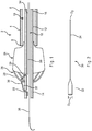
- a delivery sheath 4 has a lumen 10.
- An inner member 12 is disposed within the lumen 10 of the delivery sheath 4.
- a plurality of first openings 20 and a plurality of second openings 22 are disposed upon the proximal portion 14 of inner member 12.
- Each of the plurality of second openings 22 is disposed proximally of one of the plurality of first openings 20.
- a self-expanding medical device 24 is disposed about the proximal portion 14 of inner member 12.
- the proximal end 26 of self-expanding medical device 24 includes exposed structural members 28.
- Self-expanding medical device 24 may be a self-expanding stent, stent graft, or any other self-expanding medical device that includes exposed structural members.
- a plurality of trigger wires 30 is disposed within the lumen 18 of inner member 12.
- Trigger wire 30 has a proximal portion 32 and a distal portion 34.
- the proximal portion 32 of trigger wire 30 has a greater diameter than the diameter of distal portion 34.
- the trigger wire 30 exits the lumen 18 of inner member 12 through a first opening 20 and re-enters the lumen 18 of inner member 12 through a second opening 22 such that the proximal portion 32 of trigger wire 30 forms a bend 36.
- the transition between the first and second diameters preferably occurs within a first opening 20. Bend 36 engages and compresses exposed structural members 28 toward inner member 12, retaining self-expanding medical device 24 in position on the proximal portion 14 of inner member 12.
- Trigger wire 30 may be tapered using any of a number of suitable manufacturing methods.
- the distal portion 34 of the trigger wire 30 could be ground to reduce its diameter.
- Another method for tapering trigger wire 30 would be to overlay a thin cannula over the proximal portion 32 of trigger wire 30. Other methods not described here may also be used.
- Trigger wire 30 is configured to be withdrawn in the distal direction through the lumen 18 of inner member 12.
- an operator advances self-expanding medical device delivery system 2 through a body vessel to a desired deployment site.
- the device is advanced in its delivery configuration as shown in FIG. 4 .
- the delivery sheath 4 covers the inner member 12 and self-expanding medical device 24.
- the operator withdraws the delivery sheath 4 in the distal direction to expose the proximal portion 14 of inner member 12 and the self-expanding medical device 24 as shown in FIG. 1 .
- the operator then withdraws trigger wire 30 through lumen 18 of inner member 12.
- the operator may withdraw each of the plurality of trigger wires 30 individually through the lumen 18 of inner member 12 or withdraw each of the plurality of trigger wires 30 through the lumen 18 of inner member 12 at different rates.
- trigger wire 30 is withdrawn, proximal portion 32 of trigger wire 30 is pulled out of second opening 22 until proximal portion 32 no longer passes through second opening 22.
- proximal portion 32 is removed from second opening 22, exposed structural members 28 are no longer restrained by proximal portion 32 of trigger wire 30.
- the exposed structural members 28 expand outward to anchor self-expanding medical device 24 at the location desired by the operator.
- This configuration allows the use of a delivery sheath 4 and inner member 12 with smaller diameters than used with a trigger wire 30 of a constant diameter. Because the proximal portion 32 of trigger wire 30 is disposed proximally of the proximal end 26 of self-expanding medical device 24, self-expanding medical device 24 may be more fully compressed. Additionally, inner member 12 need only be large enough to allow the operator to withdraw one trigger wire 30 through the lumen 18 of inner member 12.
- the self-expanding medical device delivery system 2 may include the use of a guide wire 38.
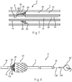
- the self-expanding medical device delivery system 2 may also include a bulbous tip 46, as shown in FIG. 8 .
- the self-expanding medical device 24 may be a stent graft.
- a plurality of trigger wires 30 is shown retaining the self-expanding medical device 24 on inner member 12, as shown in FIG. 3 .
- the first openings 20 and second openings 22 may be staggered such that each of the plurality of trigger wires 30 enters and exits the inner member 12 at different longitudinal positions. This allows the inner member 12 to be of a smaller diameter, because each of the proximal portions 32 of the plurality of trigger wires 30 are staggered such that at least one proximal portion 32 does not lie parallel to at least one other proximal portion 32 as the plurality of trigger wires 30 is withdrawn.
- Proximal portion 32 of trigger wire 30 has a diameter that can provide adequate strength to retain self-expanding medical device 24.
- the diameter of the proximal portion 32 is dependent upon the type of self-expanding medical device 24 used.
- self-expanding medical device 24 is a stent graft.
- the diameter of the proximal portion 32 required to retain a common stent graft may range from 2 to 5 times the diameter of the distal portion 34.
- the proximal portion 32 of trigger wire 30 must be long enough to form a bend 36 around the exposed structural members 28. For a typical stent graft, the proximal portion 32 may be 1 to 2 inches long.
- distal portion 34 of trigger wire 30 only requires adequate tensile strength to withdraw trigger wire 30 through lumen 18 of inner member 12.
- the required diameter of distal portion 34 is less than the diameter of proximal portion 32.
- a smaller inner member 12 may be used. In turn, this allows the use of a smaller diameter delivery sheath 4, which would result in a self-expanding medical device delivery system 2 with a lower profile.
- the distal portion 34 of trigger wire 30 must be long enough to extend from the deployment site through the vasculature and outside the body to the operator. Thus, the distal portion 34 may be up to 3 feet long.
- FIG. 5 illustrates another embodiment of the self-expanding medical device delivery system 2.
- the proximal end 42 of the proximal portion 14 of the inner member 12 is flared outward to receive the proximal portion 32 of trigger wire 30. Because the flared proximal end 42 is proximal to the self-expanding medical device 24, a smaller delivery sheath 4 may be used.
- FIGS. 6 and 7 illustrate another embodiment of the trigger wire 30.
- the proximal end 44 of the trigger wire 30 has a smaller diameter than the diameter of the proximal portion 32 of trigger wire 30.
- the proximal end 44 of trigger wire 30 is the portion of trigger wire 30 that re-enters inner member 12 through the second opening 22.
- the transition between the smaller diameter of proximal end 44 and the larger diameter of proximal portion 32 preferably occurs within the second opening 22.
- FIGS. 8 and 9 illustrate another embodiment of the self-expanding medical device delivery system 2.
- the plurality of trigger wires 130 is connected to a handle 40 at the distal end of the self-expanding medical device delivery system 2.
- FIG. 5 shows a rotary handle 40, but handle 40 may be any of several well-known devices used to pull trigger wires and other elongate devices distally through a stent delivery system, including push-pull devices, rotary devices, and devices that employ a pistol grip.
- the handle 40 may also be configured to take up each of the plurality of trigger wires 30 at different rates.
- Trigger wire 130 has a proximal portion 132, a distal portion 134, and a center portion 136.
- Proximal portion 132 has a first diameter
- distal portion 134 has a second diameter
- center portion 136 has a third diameter.
- the first diameter of proximal portion 132 is greater than the third diameter of center portion 136.
- the second diameter of distal portion 134 is also greater than the third diameter of center portion 136.
- the first diameter of proximal portion 132 may be greater than, equal to, or lesser than the second diameter of distal portion 134, depending on the diameters required to provide adequate bending strength required. As noted above, the adequate bending strength for the proximal portion 132 varies with the self-expanding medical device 24 used.
- the diameter of the proximal portion 132 required to retain a common stent graft may range from 2 to 5 times the diameter of the center portion 136.
- the proximal portion 132 of trigger wire 130 must be long enough to form a bend around the exposed structural members 28.
- the proximal portion 132 may be 1 to 2 inches long.
- distal portion 134 of trigger wire 130 is required to ensure a secure connection between distal portion 134 of trigger wire 130 and handle 40.
- the adequate bending strength for the distal portion 134 varies with the handle 40 used.
- the length of distal portion 134 also varies based on the type of handle 40 used.
- Center portion 136 of trigger wire 130 only requires adequate tensile strength to withdraw trigger wire 130 through lumen 18 of inner member 12. Thus, the required diameter of center portion 136 is less than the diameter of proximal portion 132 and distal portion 134.
- a trigger wire 130 with a decreased diameter in center portion 136 is desirable to lower the profile of self-expanding medical device delivery system 2.
- the center portion 136 of trigger wire 130 must be long enough to extend from the deployment site through the vasculature and to the distal portion 134. Thus, the center portion 136 may be up to 3 feet long.
- the transition between the smaller diameter of center portion 136 and the larger diameter of proximal portion 132 preferably occurs within a first opening 20.
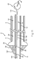
- FIGS. 10 and 11 illustrate another embodiment of trigger wire 130.
- the trigger wire 130 has proximal portion 132, a distal portion 134, and a center portion 136.
- the proximal portion 132 has a proximal end 144.
- the proximal portion 132 has a first diameter
- distal portion 134 has a second diameter
- center portion 136 has a third diameter
- the proximal end 144 of the proximal portion 132 has a fourth diameter.
- the first diameter of proximal portion 132 is greater than the third diameter of center portion 136.
- the second diameter of distal portion 134 is also greater than the third diameter of center portion 136.
- the first diameter of proximal portion 132 is greater than the fourth diameter of the proximal end 144 of proximal portion 132.
- the first diameter of proximal portion 132 may be greater than, equal to, or lesser than the second diameter of distal portion 134, depending on the diameters required to provide adequate bending strength.
- the third diameter of center portion 136 may be greater than, equal to, or lesser than the fourth diameter of the proximal end 144 of the proximal portion 132, depending on the diameters required to provide adequate tensile strength.
- the proximal end 144 of trigger wire 130 is the portion of trigger wire 130 that re-enters inner member 12 through one of the plurality of second openings 22.
- the transition between the smaller diameter of proximal end 144 and the larger diameter of proximal portion 132 preferably occurs within a second opening 22.
Landscapes
- Health & Medical Sciences (AREA)
- Engineering & Computer Science (AREA)
- Biomedical Technology (AREA)
- Heart & Thoracic Surgery (AREA)
- Oral & Maxillofacial Surgery (AREA)
- Transplantation (AREA)
- Cardiology (AREA)
- Vascular Medicine (AREA)
- Life Sciences & Earth Sciences (AREA)
- Animal Behavior & Ethology (AREA)
- General Health & Medical Sciences (AREA)
- Public Health (AREA)
- Veterinary Medicine (AREA)
- Pulmonology (AREA)
- Gastroenterology & Hepatology (AREA)
- Media Introduction/Drainage Providing Device (AREA)
Claims (10)
- Zuführsystem für eine selbstexpandierende medizinische Vorrichtung, umfassend:eine Zuführhülse mit einem Lumen und einem proximalen Abschnitt,ein inneres Glied, das teilweise in dem Lumen der Zuführhülse angeordnet ist, wobei das innere Glied ein Lumen und einen proximalen Abschnitt und ein distales Ende hat, wobei der proximale Abschnitt des inneren Glieds eine Vielzahl von ersten Öffnungen und eine Vielzahl von zweiten Öffnungen hat, wobei die zweite Öffnung proximal zu der ersten Öffnung angeordnet ist,eine selbstexpandierende medizinische Vorrichtung, die um das proximale Ende des inneren Glieds herum angeordnet ist, wobei die selbstexpandierende medizinische Vorrichtung ein proximales Ende hat, wobei die selbstexpandierende medizinische Vorrichtung freiliegende Strukturglieder am proximalen Ende der selbstexpandierenden medizinischen Vorrichtung hat,eine Vielzahl von Auslöserdrähten, die teilweise in dem Lumen des inneren Glieds angeordnet sind, wobei die Vielzahl von Auslöserdrähten durch eine der Vielzahl von ersten Öffnungen aus dem Lumen des inneren Glieds austreten und durch eine der Vielzahl von zweiten Öffnungen wieder in das Lumen des inneren Glieds eintreten, so dass der proximale Abschnitt des Auslöserdrahts eine Biegung bildet, wobei die Biegung des Auslöserdrahts die freiliegenden Strukturglieder in Eingriff nimmt, und so dass die freiliegenden Strukturglieder zusammengedrückt werden und die selbstexpandierende medizinische Vorrichtung durch den proximalen Abschnitt des Auslöserdrahts gehalten wird, undwobei die Vielzahl von Auslöserdrähten dazu konfiguriert sind, in der distalen Richtung durch das Lumen des inneren Glieds zurückgezogen zu werden, so dass die Auslöserdrähte die freiliegenden Strukturglieder aushaken und die selbstexpandierende medizinische Vorrichtung freigeben, dadurch gekennzeichnet, dass die Auslöserdrähte einen proximalen Abschnitt mit einem ersten Durchmesser und einen ersten distalen Abschnitt mit einem zweiten Durchmesser haben, wobei der erste Durchmesser größer als der zweite Durchmesser ist.
- Zuführsystem nach Anspruch 1, wobei der erste Durchmesser des Auslöserdrahts doppelt so groß bis fünf Mal so groß wie der zweite Durchmesser des Auslöserdrahts ist.
- Zuführsystem nach Anspruch 1, wobei die selbstexpandierende medizinische Vorrichtung ein Stentgraft ist.
- Zuführsystem nach Anspruch 1, wobei die selbstexpandierende medizinische Vorrichtung ein selbstexpandierender Stent ist.
- Zuführsystem nach Anspruch 1, ferner umfassend einen Führungsdraht, der teilweise in der Zuführhülse angeordnet ist und ein proximales Ende hat, wobei sich das proximale Ende des Führungsdrahts über den proximalsten Abschnitt des inneren Glieds hinaus erstreckt.
- Zuführsystem nach Anspruch 1 mit einer Zuführkonfiguration, wobei der proximale Abschnitt des Auslöserdrahts in der Zuführkonfiguration proximal zu der ersten Öffnung liegt.
- Zuführsystem nach Anspruch 1, wobei jede der Vielzahl von ersten Öffnungen mit unterschiedlichem Abstand vom distalen Ende des inneren Glieds positioniert ist und jede der Vielzahl von zweiten Öffnungen mit unterschiedlichem Abstand vom distalen Ende des inneren Glieds positioniert ist.
- Zuführsystem nach Anspruch 1, wobei der proximale Abschnitt des inneren Glieds ein proximales Ende hat, wobei der proximale Abschnitt des inneren Glieds nach außen aufgeweitet ist.
- Zuführsystem nach Anspruch 1, wobei der proximale Abschnitt des Auslöserdrahts ein proximales Ende hat, wobei das proximale Ende einen dritten Durchmesser hat, wobei der erste Durchmesser größer als der dritte Durchmesser ist.
- Zuführsystem nach Anspruch 1, wobei der Auslöserdraht einen zweiten distalen Abschnitt mit einem vierten Durchmesser hat, wobei der erste distale Abschnitt ein mittlerer Abschnitt zwischen dem proximalen Abschnitt und dem zweiten distalen Abschnitt ist, wobei der vierte Durchmesser größer als der zweite Durchmesser ist.
Applications Claiming Priority (2)
| Application Number | Priority Date | Filing Date | Title |
|---|---|---|---|
| US12/786,109 US8523932B2 (en) | 2010-05-24 | 2010-05-24 | Variable diameter trigger wire |
| PCT/US2011/036587 WO2011149693A1 (en) | 2010-05-24 | 2011-05-16 | Variable diameter trigger wire |
Publications (2)
| Publication Number | Publication Date |
|---|---|
| EP2575679A1 EP2575679A1 (de) | 2013-04-10 |
| EP2575679B1 true EP2575679B1 (de) | 2016-12-14 |
Family
ID=44533057
Family Applications (1)
| Application Number | Title | Priority Date | Filing Date |
|---|---|---|---|
| EP11725833.5A Not-in-force EP2575679B1 (de) | 2010-05-24 | 2011-05-16 | Abzugsdraht mit veräbnderlichem durchmesser |
Country Status (3)
| Country | Link |
|---|---|
| US (1) | US8523932B2 (de) |
| EP (1) | EP2575679B1 (de) |
| WO (1) | WO2011149693A1 (de) |
Families Citing this family (32)
| Publication number | Priority date | Publication date | Assignee | Title |
|---|---|---|---|---|
| US9387312B2 (en) | 2008-09-15 | 2016-07-12 | Brightwater Medical, Inc. | Convertible nephroureteral catheter |
| GB2464977B (en) | 2008-10-31 | 2010-11-03 | William Cook Europe As | Introducer for deploying a stent graft in a curved lumen and stent graft therefor |
| US11376114B2 (en) | 2008-10-31 | 2022-07-05 | Cook Medical Technologies Llc | Introducer for deploying a stent graft in a curved lumen and stent graft therefor |
| DE102009055969A1 (de) * | 2009-11-27 | 2011-06-01 | Transcatheter Technologies Gmbh | Vorrichtung und Set zum Falten oder Entfalten eines medizinischen Implantats und Verfahren |
| AU2011270933A1 (en) * | 2010-06-24 | 2013-01-31 | Cordis Corporation | Apparatus for and method of pulling a tensile member from a medical device |
| US10117765B2 (en) * | 2011-06-14 | 2018-11-06 | W.L. Gore Associates, Inc | Apposition fiber for use in endoluminal deployment of expandable implants |
| US9877858B2 (en) | 2011-11-14 | 2018-01-30 | W. L. Gore & Associates, Inc. | External steerable fiber for use in endoluminal deployment of expandable devices |
| US9782282B2 (en) | 2011-11-14 | 2017-10-10 | W. L. Gore & Associates, Inc. | External steerable fiber for use in endoluminal deployment of expandable devices |
| US9364359B2 (en) * | 2011-12-08 | 2016-06-14 | W. L. Gore & Associates, Inc. | Systems and methods for delivery of a medical device |
| EP2604232B1 (de) | 2011-12-14 | 2021-02-24 | Cook Medical Technologies LLC | Ringauslösungsdraht zum Einsetzen einer endoluminalen Prothese |
| US9375308B2 (en) | 2012-03-13 | 2016-06-28 | W. L. Gore & Associates, Inc. | External steerable fiber for use in endoluminal deployment of expandable devices |
| US9855129B2 (en) * | 2012-10-31 | 2018-01-02 | Cook Medical Technologies Llc | Multi-level suture attachments for coupling a stent to graft material |
| US9750626B2 (en) * | 2012-10-31 | 2017-09-05 | Cook Medical Technologies Llc | Apparatus and methods for improved stent deployment |
| EP2727562A1 (de) * | 2012-10-31 | 2014-05-07 | Cook Medical Technologies LLC | Kanülenbefestigung in endoluminalen Abgabevorrichtungen |
| US9622893B2 (en) | 2012-12-20 | 2017-04-18 | Cook Medical Technologies Llc | Apparatus and method for improved deployment of endovascular grafts |
| US10265202B2 (en) * | 2013-03-14 | 2019-04-23 | Cook Medical Technologies Llc | Prosthesis having an everting pivoting fenestration |
| CN106029012B (zh) * | 2014-01-20 | 2020-05-08 | 麦瑞通医疗系统公司 | 可转换式肾输尿管导管 |
| EP3179958B1 (de) | 2014-08-12 | 2021-10-20 | Merit Medical Systems, Inc. | Systeme zur kopplung und entkopplung eines katheter |
| FR3027494B1 (fr) * | 2014-10-28 | 2017-09-15 | Sylvain Creton | Lacet de chaussure |
| EP3040056B1 (de) * | 2014-12-29 | 2019-09-11 | Cook Medical Technologies LLC | System zum einsetzen einer prothese |
| US10575951B2 (en) | 2015-08-26 | 2020-03-03 | Edwards Lifesciences Cardiaq Llc | Delivery device and methods of use for transapical delivery of replacement mitral valve |
| US10500046B2 (en) * | 2015-12-14 | 2019-12-10 | Medtronic, Inc. | Delivery system having retractable wires as a coupling mechanism and a deployment mechanism for a self-expanding prosthesis |
| JP6883115B2 (ja) | 2017-03-08 | 2021-06-09 | ダブリュ.エル.ゴア アンド アソシエイツ,インコーポレイティドW.L. Gore & Associates, Incorporated | 角度付け用ステアリングワイヤーアタッチ |
| US10709541B2 (en) | 2017-04-28 | 2020-07-14 | Cook Medical Technologies Llc | Systems and methods for adjusting the diameter of an endoluminal prosthesis and an endoluminal prosthesis configured for the same |
| US11051939B2 (en) * | 2017-08-31 | 2021-07-06 | Edwards Lifesciences Corporation | Active introducer sheath system |
| CA3076375C (en) * | 2017-09-20 | 2022-08-09 | Sinopsys Surgical, Inc. | Paranasal sinus fluid access implantation tools, assemblies, kits and methods |
| CN112638320B (zh) | 2018-08-31 | 2024-07-30 | W.L.戈尔及同仁股份有限公司 | 用于使可植入医疗装置转向的设备、系统和方法 |
| EP3843658B1 (de) | 2018-08-31 | 2024-04-17 | W. L. Gore & Associates, Inc. | System zur lenkung eines implantierbaren medizinprodukts |
| US12226327B2 (en) | 2020-04-15 | 2025-02-18 | Merit Medical Systems, Inc. | Systems and methods for coupling and decoupling a catheter |
| US12491097B2 (en) | 2020-06-05 | 2025-12-09 | Merit Medical Systems, Inc. | Systems and methods for coupling and decoupling a catheter |
| GB2605559B (en) | 2021-01-07 | 2023-04-05 | Cook Medical Technologies Llc | Stent graft |
| GB2631689B (en) | 2023-07-05 | 2026-04-29 | Cook Medical Technologies Llc | Medical Device System |
Family Cites Families (33)
| Publication number | Priority date | Publication date | Assignee | Title |
|---|---|---|---|---|
| US4813934A (en) * | 1987-08-07 | 1989-03-21 | Target Therapeutics | Valved catheter device and method |
| AU6495794A (en) | 1993-03-30 | 1994-10-24 | Instent Inc. | Temporary stent system |
| US6090115A (en) * | 1995-06-07 | 2000-07-18 | Intratherapeutics, Inc. | Temporary stent system |
| US5404887A (en) * | 1993-11-04 | 1995-04-11 | Scimed Life Systems, Inc. | Guide wire having an unsmooth exterior surface |
| US5800517A (en) * | 1996-08-19 | 1998-09-01 | Scimed Life Systems, Inc. | Stent delivery system with storage sleeve |
| US7491216B2 (en) | 1997-11-07 | 2009-02-17 | Salviac Limited | Filter element with retractable guidewire tip |
| US5910144A (en) | 1998-01-09 | 1999-06-08 | Endovascular Technologies, Inc. | Prosthesis gripping system and method |
| US5946779A (en) * | 1998-07-10 | 1999-09-07 | Taiwan Paiho Limited | Shoelace having sections of different diameters and densities |
| US6019779A (en) * | 1998-10-09 | 2000-02-01 | Intratherapeutics Inc. | Multi-filar coil medical stent |
| US20030171642A1 (en) * | 2002-03-05 | 2003-09-11 | Schock Robert B. | Intra-aortic balloon catheter having a releasable guide wire |
| US6833003B2 (en) | 2002-06-24 | 2004-12-21 | Cordis Neurovascular | Expandable stent and delivery system |
| US7722657B2 (en) | 2002-08-23 | 2010-05-25 | William A. Cook Australia Pty. Ltd. | Asymmetric stent graft attachment |
| US20050038503A1 (en) | 2003-05-29 | 2005-02-17 | Secor Medical, Llc | Filament based prosthesis |
| US7470282B2 (en) | 2003-06-30 | 2008-12-30 | Boston Scientific Scimed, Inc. | Stent grip and system for use therewith |
| US20050055077A1 (en) | 2003-09-05 | 2005-03-10 | Doron Marco | Very low profile medical device system having an adjustable balloon |
| US7758626B2 (en) | 2004-07-20 | 2010-07-20 | Medtronic Vascular, Inc. | Device and method for delivering an endovascular stent-graft having a longitudinally unsupported portion |
| US20090105753A1 (en) * | 2004-08-26 | 2009-04-23 | Prodesco, Inc. | Sutures and methods of making the same |
| EP3175827B1 (de) | 2004-12-15 | 2019-03-06 | Cook Medical Technologies LLC | Katheter mit mehradrigen kabeln |
| WO2007014088A2 (en) | 2005-07-25 | 2007-02-01 | Cook Incorporated | Intraluminal prosthesis and stent |
| US20070060846A1 (en) * | 2005-09-15 | 2007-03-15 | Wilson-Cook Medical Inc. | Multiple stage wire guide |
| US8518098B2 (en) * | 2006-02-21 | 2013-08-27 | Cook Medical Technologies Llc | Split sheath deployment system |
| EP1991179B1 (de) | 2006-02-27 | 2013-03-20 | William A. Cook Australia Pty. Ltd. | Stentfixierung |
| EP1997902B1 (de) | 2006-03-30 | 2013-09-18 | Hiroshima University | Screening-verfahren |
| JP5250748B2 (ja) * | 2006-06-02 | 2013-07-31 | ウィリアム・エイ・クック・オーストラリア・プロプライエタリー・リミテッド | マルチポートデリバリー装置 |
| EP3338735A1 (de) | 2006-07-19 | 2018-06-27 | Novate Medical Limited | Vaskulärer filter |
| US9278017B2 (en) * | 2006-11-30 | 2016-03-08 | Cook Medical Technologies Llc | Implant release mechanism |
| US8092510B2 (en) | 2007-07-25 | 2012-01-10 | Cook Medical Technologies Llc | Retention wire for self-expanding stent |
| US8226701B2 (en) * | 2007-09-26 | 2012-07-24 | Trivascular, Inc. | Stent and delivery system for deployment thereof |
| US8163007B2 (en) | 2008-02-08 | 2012-04-24 | Cook Medical Technologies Llc | Stent designs for use with one or more trigger wires |
| CN103637861B (zh) * | 2008-02-29 | 2016-05-25 | 爱德华兹生命科学公司 | 用于部署假体装置的可扩展元件 |
| WO2010042210A1 (en) | 2008-10-10 | 2010-04-15 | William Cook Europe Aps | Apparatus for curving an implantable medical device in a lumen |
| GB0822110D0 (en) * | 2008-12-03 | 2009-01-07 | Angiomed Ag | Catheter sheath for implant delivery |
| US8425554B2 (en) * | 2008-12-16 | 2013-04-23 | Arthrex, Inc. | Suture passing K-wire |
-
2010
- 2010-05-24 US US12/786,109 patent/US8523932B2/en not_active Expired - Fee Related
-
2011
- 2011-05-16 WO PCT/US2011/036587 patent/WO2011149693A1/en not_active Ceased
- 2011-05-16 EP EP11725833.5A patent/EP2575679B1/de not_active Not-in-force
Also Published As
| Publication number | Publication date |
|---|---|
| US20110288624A1 (en) | 2011-11-24 |
| US8523932B2 (en) | 2013-09-03 |
| EP2575679A1 (de) | 2013-04-10 |
| WO2011149693A1 (en) | 2011-12-01 |
Similar Documents
| Publication | Publication Date | Title |
|---|---|---|
| US8523932B2 (en) | Variable diameter trigger wire | |
| US8696732B2 (en) | Stent delivery system | |
| CN112089466B (zh) | 用于血管内装置的牵拉线分离 | |
| CN109864836B (zh) | 用于耦合和解耦导管的系统和方法 | |
| CN104042299B (zh) | 具有机械拆卸的闭塞装置递送系统 | |
| US10258376B2 (en) | Medical devices and systems for manipulating foreign bodies and methods of using the same | |
| CN101854871B (zh) | 治疗体腔的系留线圈 | |
| EP3244844B1 (de) | Freisetzungssystem für naht- und drahtstent | |
| EP2604232B1 (de) | Ringauslösungsdraht zum Einsetzen einer endoluminalen Prothese | |
| JP2018535736A5 (de) | ||
| EP2706930B1 (de) | Rückholvorrichtung mit lösbar befestigter schlinge | |
| EP2777648B1 (de) | Rohrerfassungsmechanismus zum Abliefern und Lösen eines Stents | |
| EP2133043A1 (de) | Stent-Einführungssystem und Stent-Einführungsverfahren | |
| US10159489B2 (en) | Systems and methods for delivering multiple embolization coils | |
| EP3047821B1 (de) | Abgabevorrichtung mit einem expandierbaren teil | |
| CN109984877B (zh) | 管腔支架系统 | |
| CN103732282A (zh) | 具有两个柔性端部的引导线和利用其进入分支血管的方法 | |
| EP3225219B1 (de) | Distale erfassungsvorrichtung für einen selbstexpandierbaren stent | |
| EP3072552A1 (de) | Medizinische vorrichtung mit vorspannelement | |
| EP2745871B1 (de) | Führungsdraht | |
| US11000300B2 (en) | Magnetically coupled vascular snare system and method | |
| EP3395391B1 (de) | Führungsdrahtführungsvorrichtung und führungsdrahtführungsanordnung | |
| US11304837B2 (en) | Implantable device delivery system | |
| US8257422B2 (en) | Over-the-wire detachment mechanism | |
| EP2555823B1 (de) | Klemme für schleifenspitzenvorrichtungen |
Legal Events
| Date | Code | Title | Description |
|---|---|---|---|
| PUAI | Public reference made under article 153(3) epc to a published international application that has entered the european phase |
Free format text: ORIGINAL CODE: 0009012 |
|
| 17P | Request for examination filed |
Effective date: 20121123 |
|
| AK | Designated contracting states |
Kind code of ref document: A1 Designated state(s): AL AT BE BG CH CY CZ DE DK EE ES FI FR GB GR HR HU IE IS IT LI LT LU LV MC MK MT NL NO PL PT RO RS SE SI SK SM TR |
|
| DAX | Request for extension of the european patent (deleted) | ||
| REG | Reference to a national code |
Ref country code: DE Ref legal event code: R079 Ref document number: 602011033374 Country of ref document: DE Free format text: PREVIOUS MAIN CLASS: A61F0002060000 Ipc: A61F0002950000 |
|
| GRAP | Despatch of communication of intention to grant a patent |
Free format text: ORIGINAL CODE: EPIDOSNIGR1 |
|
| RIC1 | Information provided on ipc code assigned before grant |
Ipc: A61F 2/95 20130101AFI20160608BHEP |
|
| INTG | Intention to grant announced |
Effective date: 20160704 |
|
| GRAS | Grant fee paid |
Free format text: ORIGINAL CODE: EPIDOSNIGR3 |
|
| GRAA | (expected) grant |
Free format text: ORIGINAL CODE: 0009210 |
|
| AK | Designated contracting states |
Kind code of ref document: B1 Designated state(s): AL AT BE BG CH CY CZ DE DK EE ES FI FR GB GR HR HU IE IS IT LI LT LU LV MC MK MT NL NO PL PT RO RS SE SI SK SM TR |
|
| REG | Reference to a national code |
Ref country code: GB Ref legal event code: FG4D |
|
| REG | Reference to a national code |
Ref country code: CH Ref legal event code: EP |
|
| REG | Reference to a national code |
Ref country code: IE Ref legal event code: FG4D |
|
| REG | Reference to a national code |
Ref country code: AT Ref legal event code: REF Ref document number: 852880 Country of ref document: AT Kind code of ref document: T Effective date: 20170115 |
|
| REG | Reference to a national code |
Ref country code: DE Ref legal event code: R096 Ref document number: 602011033374 Country of ref document: DE |
|
| PG25 | Lapsed in a contracting state [announced via postgrant information from national office to epo] |
Ref country code: LV Free format text: LAPSE BECAUSE OF FAILURE TO SUBMIT A TRANSLATION OF THE DESCRIPTION OR TO PAY THE FEE WITHIN THE PRESCRIBED TIME-LIMIT Effective date: 20161214 |
|
| REG | Reference to a national code |
Ref country code: LT Ref legal event code: MG4D |
|
| REG | Reference to a national code |
Ref country code: NL Ref legal event code: MP Effective date: 20161214 |
|
| PG25 | Lapsed in a contracting state [announced via postgrant information from national office to epo] |
Ref country code: SE Free format text: LAPSE BECAUSE OF FAILURE TO SUBMIT A TRANSLATION OF THE DESCRIPTION OR TO PAY THE FEE WITHIN THE PRESCRIBED TIME-LIMIT Effective date: 20161214 Ref country code: LT Free format text: LAPSE BECAUSE OF FAILURE TO SUBMIT A TRANSLATION OF THE DESCRIPTION OR TO PAY THE FEE WITHIN THE PRESCRIBED TIME-LIMIT Effective date: 20161214 Ref country code: NO Free format text: LAPSE BECAUSE OF FAILURE TO SUBMIT A TRANSLATION OF THE DESCRIPTION OR TO PAY THE FEE WITHIN THE PRESCRIBED TIME-LIMIT Effective date: 20170314 Ref country code: GR Free format text: LAPSE BECAUSE OF FAILURE TO SUBMIT A TRANSLATION OF THE DESCRIPTION OR TO PAY THE FEE WITHIN THE PRESCRIBED TIME-LIMIT Effective date: 20170315 |
|
| REG | Reference to a national code |
Ref country code: AT Ref legal event code: MK05 Ref document number: 852880 Country of ref document: AT Kind code of ref document: T Effective date: 20161214 |
|
| PG25 | Lapsed in a contracting state [announced via postgrant information from national office to epo] |
Ref country code: RS Free format text: LAPSE BECAUSE OF FAILURE TO SUBMIT A TRANSLATION OF THE DESCRIPTION OR TO PAY THE FEE WITHIN THE PRESCRIBED TIME-LIMIT Effective date: 20161214 Ref country code: HR Free format text: LAPSE BECAUSE OF FAILURE TO SUBMIT A TRANSLATION OF THE DESCRIPTION OR TO PAY THE FEE WITHIN THE PRESCRIBED TIME-LIMIT Effective date: 20161214 Ref country code: FI Free format text: LAPSE BECAUSE OF FAILURE TO SUBMIT A TRANSLATION OF THE DESCRIPTION OR TO PAY THE FEE WITHIN THE PRESCRIBED TIME-LIMIT Effective date: 20161214 |
|
| PG25 | Lapsed in a contracting state [announced via postgrant information from national office to epo] |
Ref country code: NL Free format text: LAPSE BECAUSE OF FAILURE TO SUBMIT A TRANSLATION OF THE DESCRIPTION OR TO PAY THE FEE WITHIN THE PRESCRIBED TIME-LIMIT Effective date: 20161214 |
|
| PG25 | Lapsed in a contracting state [announced via postgrant information from national office to epo] |
Ref country code: CZ Free format text: LAPSE BECAUSE OF FAILURE TO SUBMIT A TRANSLATION OF THE DESCRIPTION OR TO PAY THE FEE WITHIN THE PRESCRIBED TIME-LIMIT Effective date: 20161214 Ref country code: RO Free format text: LAPSE BECAUSE OF FAILURE TO SUBMIT A TRANSLATION OF THE DESCRIPTION OR TO PAY THE FEE WITHIN THE PRESCRIBED TIME-LIMIT Effective date: 20161214 Ref country code: IS Free format text: LAPSE BECAUSE OF FAILURE TO SUBMIT A TRANSLATION OF THE DESCRIPTION OR TO PAY THE FEE WITHIN THE PRESCRIBED TIME-LIMIT Effective date: 20170414 Ref country code: EE Free format text: LAPSE BECAUSE OF FAILURE TO SUBMIT A TRANSLATION OF THE DESCRIPTION OR TO PAY THE FEE WITHIN THE PRESCRIBED TIME-LIMIT Effective date: 20161214 Ref country code: SK Free format text: LAPSE BECAUSE OF FAILURE TO SUBMIT A TRANSLATION OF THE DESCRIPTION OR TO PAY THE FEE WITHIN THE PRESCRIBED TIME-LIMIT Effective date: 20161214 |
|
| PG25 | Lapsed in a contracting state [announced via postgrant information from national office to epo] |
Ref country code: BE Free format text: LAPSE BECAUSE OF FAILURE TO SUBMIT A TRANSLATION OF THE DESCRIPTION OR TO PAY THE FEE WITHIN THE PRESCRIBED TIME-LIMIT Effective date: 20161214 Ref country code: PT Free format text: LAPSE BECAUSE OF FAILURE TO SUBMIT A TRANSLATION OF THE DESCRIPTION OR TO PAY THE FEE WITHIN THE PRESCRIBED TIME-LIMIT Effective date: 20170414 Ref country code: AT Free format text: LAPSE BECAUSE OF FAILURE TO SUBMIT A TRANSLATION OF THE DESCRIPTION OR TO PAY THE FEE WITHIN THE PRESCRIBED TIME-LIMIT Effective date: 20161214 Ref country code: ES Free format text: LAPSE BECAUSE OF FAILURE TO SUBMIT A TRANSLATION OF THE DESCRIPTION OR TO PAY THE FEE WITHIN THE PRESCRIBED TIME-LIMIT Effective date: 20161214 Ref country code: IT Free format text: LAPSE BECAUSE OF FAILURE TO SUBMIT A TRANSLATION OF THE DESCRIPTION OR TO PAY THE FEE WITHIN THE PRESCRIBED TIME-LIMIT Effective date: 20161214 Ref country code: LU Free format text: LAPSE BECAUSE OF NON-PAYMENT OF DUE FEES Effective date: 20170531 Ref country code: PL Free format text: LAPSE BECAUSE OF FAILURE TO SUBMIT A TRANSLATION OF THE DESCRIPTION OR TO PAY THE FEE WITHIN THE PRESCRIBED TIME-LIMIT Effective date: 20161214 Ref country code: SM Free format text: LAPSE BECAUSE OF FAILURE TO SUBMIT A TRANSLATION OF THE DESCRIPTION OR TO PAY THE FEE WITHIN THE PRESCRIBED TIME-LIMIT Effective date: 20161214 Ref country code: BG Free format text: LAPSE BECAUSE OF FAILURE TO SUBMIT A TRANSLATION OF THE DESCRIPTION OR TO PAY THE FEE WITHIN THE PRESCRIBED TIME-LIMIT Effective date: 20170314 |
|
| REG | Reference to a national code |
Ref country code: DE Ref legal event code: R097 Ref document number: 602011033374 Country of ref document: DE |
|
| PLBE | No opposition filed within time limit |
Free format text: ORIGINAL CODE: 0009261 |
|
| STAA | Information on the status of an ep patent application or granted ep patent |
Free format text: STATUS: NO OPPOSITION FILED WITHIN TIME LIMIT |
|
| 26N | No opposition filed |
Effective date: 20170915 |
|
| PG25 | Lapsed in a contracting state [announced via postgrant information from national office to epo] |
Ref country code: DK Free format text: LAPSE BECAUSE OF FAILURE TO SUBMIT A TRANSLATION OF THE DESCRIPTION OR TO PAY THE FEE WITHIN THE PRESCRIBED TIME-LIMIT Effective date: 20161214 |
|
| REG | Reference to a national code |
Ref country code: CH Ref legal event code: PL |
|
| PG25 | Lapsed in a contracting state [announced via postgrant information from national office to epo] |
Ref country code: MC Free format text: LAPSE BECAUSE OF FAILURE TO SUBMIT A TRANSLATION OF THE DESCRIPTION OR TO PAY THE FEE WITHIN THE PRESCRIBED TIME-LIMIT Effective date: 20161214 |
|
| PG25 | Lapsed in a contracting state [announced via postgrant information from national office to epo] |
Ref country code: CH Free format text: LAPSE BECAUSE OF NON-PAYMENT OF DUE FEES Effective date: 20170531 Ref country code: LI Free format text: LAPSE BECAUSE OF NON-PAYMENT OF DUE FEES Effective date: 20170531 Ref country code: SI Free format text: LAPSE BECAUSE OF FAILURE TO SUBMIT A TRANSLATION OF THE DESCRIPTION OR TO PAY THE FEE WITHIN THE PRESCRIBED TIME-LIMIT Effective date: 20161214 |
|
| REG | Reference to a national code |
Ref country code: FR Ref legal event code: ST Effective date: 20180131 |
|
| PG25 | Lapsed in a contracting state [announced via postgrant information from national office to epo] |
Ref country code: LU Free format text: LAPSE BECAUSE OF NON-PAYMENT OF DUE FEES Effective date: 20170516 |
|
| PG25 | Lapsed in a contracting state [announced via postgrant information from national office to epo] |
Ref country code: FR Free format text: LAPSE BECAUSE OF NON-PAYMENT OF DUE FEES Effective date: 20170531 |
|
| PG25 | Lapsed in a contracting state [announced via postgrant information from national office to epo] |
Ref country code: MT Free format text: LAPSE BECAUSE OF NON-PAYMENT OF DUE FEES Effective date: 20170516 |
|
| PG25 | Lapsed in a contracting state [announced via postgrant information from national office to epo] |
Ref country code: HU Free format text: LAPSE BECAUSE OF FAILURE TO SUBMIT A TRANSLATION OF THE DESCRIPTION OR TO PAY THE FEE WITHIN THE PRESCRIBED TIME-LIMIT; INVALID AB INITIO Effective date: 20110516 |
|
| PG25 | Lapsed in a contracting state [announced via postgrant information from national office to epo] |
Ref country code: CY Free format text: LAPSE BECAUSE OF NON-PAYMENT OF DUE FEES Effective date: 20161214 |
|
| PG25 | Lapsed in a contracting state [announced via postgrant information from national office to epo] |
Ref country code: MK Free format text: LAPSE BECAUSE OF FAILURE TO SUBMIT A TRANSLATION OF THE DESCRIPTION OR TO PAY THE FEE WITHIN THE PRESCRIBED TIME-LIMIT Effective date: 20161214 |
|
| PG25 | Lapsed in a contracting state [announced via postgrant information from national office to epo] |
Ref country code: TR Free format text: LAPSE BECAUSE OF FAILURE TO SUBMIT A TRANSLATION OF THE DESCRIPTION OR TO PAY THE FEE WITHIN THE PRESCRIBED TIME-LIMIT Effective date: 20161214 |
|
| PG25 | Lapsed in a contracting state [announced via postgrant information from national office to epo] |
Ref country code: AL Free format text: LAPSE BECAUSE OF FAILURE TO SUBMIT A TRANSLATION OF THE DESCRIPTION OR TO PAY THE FEE WITHIN THE PRESCRIBED TIME-LIMIT Effective date: 20161214 |
|
| P01 | Opt-out of the competence of the unified patent court (upc) registered |
Effective date: 20230602 |
|
| PGFP | Annual fee paid to national office [announced via postgrant information from national office to epo] |
Ref country code: IE Payment date: 20240425 Year of fee payment: 14 |
|
| PGFP | Annual fee paid to national office [announced via postgrant information from national office to epo] |
Ref country code: GB Payment date: 20240411 Year of fee payment: 14 |
|
| PGFP | Annual fee paid to national office [announced via postgrant information from national office to epo] |
Ref country code: DE Payment date: 20240411 Year of fee payment: 14 |
|
| REG | Reference to a national code |
Ref country code: DE Ref legal event code: R119 Ref document number: 602011033374 Country of ref document: DE |
|
| GBPC | Gb: european patent ceased through non-payment of renewal fee |
Effective date: 20250516 |
|
| PG25 | Lapsed in a contracting state [announced via postgrant information from national office to epo] |
Ref country code: GB Free format text: LAPSE BECAUSE OF NON-PAYMENT OF DUE FEES Effective date: 20250516 |
|
| PG25 | Lapsed in a contracting state [announced via postgrant information from national office to epo] |
Ref country code: IE Free format text: LAPSE BECAUSE OF NON-PAYMENT OF DUE FEES Effective date: 20250516 Ref country code: DE Free format text: LAPSE BECAUSE OF NON-PAYMENT OF DUE FEES Effective date: 20251202 |