EP2706552B1 - Ensemble bras de contact fixe pour disjoncteur à boîtier moulé - Google Patents
Ensemble bras de contact fixe pour disjoncteur à boîtier moulé Download PDFInfo
- Publication number
- EP2706552B1 EP2706552B1 EP13183128.1A EP13183128A EP2706552B1 EP 2706552 B1 EP2706552 B1 EP 2706552B1 EP 13183128 A EP13183128 A EP 13183128A EP 2706552 B1 EP2706552 B1 EP 2706552B1
- Authority
- EP
- European Patent Office
- Prior art keywords
- contact arm
- stationary contact
- circuit breaker
- elastic support
- molded case
- Prior art date
- Legal status (The legal status is an assumption and is not a legal conclusion. Google has not performed a legal analysis and makes no representation as to the accuracy of the status listed.)
- Not-in-force
Links
- 230000002265 prevention Effects 0.000 claims description 14
- 230000035515 penetration Effects 0.000 claims description 9
- 229910000831 Steel Inorganic materials 0.000 claims description 8
- 239000010959 steel Substances 0.000 claims description 8
- 230000035699 permeability Effects 0.000 claims description 3
- 238000000034 method Methods 0.000 description 8
- 230000008569 process Effects 0.000 description 5
- 230000006870 function Effects 0.000 description 4
- 230000007246 mechanism Effects 0.000 description 4
- 239000000470 constituent Substances 0.000 description 3
- 230000008878 coupling Effects 0.000 description 2
- 238000010168 coupling process Methods 0.000 description 2
- 238000005859 coupling reaction Methods 0.000 description 2
- 230000002708 enhancing effect Effects 0.000 description 2
- 238000004519 manufacturing process Methods 0.000 description 2
- 230000003245 working effect Effects 0.000 description 2
- 230000002159 abnormal effect Effects 0.000 description 1
- 230000000694 effects Effects 0.000 description 1
- 238000005516 engineering process Methods 0.000 description 1
- 230000001939 inductive effect Effects 0.000 description 1
- 238000009434 installation Methods 0.000 description 1
- 239000002184 metal Substances 0.000 description 1
- 230000009993 protective function Effects 0.000 description 1
- 230000035939 shock Effects 0.000 description 1
- 229920003002 synthetic resin Polymers 0.000 description 1
- 239000000057 synthetic resin Substances 0.000 description 1
- 238000003466 welding Methods 0.000 description 1
Images
Classifications
-
- H—ELECTRICITY
- H01—ELECTRIC ELEMENTS
- H01H—ELECTRIC SWITCHES; RELAYS; SELECTORS; EMERGENCY PROTECTIVE DEVICES
- H01H71/00—Details of the protective switches or relays covered by groups H01H73/00 - H01H83/00
- H01H71/08—Terminals; Connections
-
- H—ELECTRICITY
- H01—ELECTRIC ELEMENTS
- H01H—ELECTRIC SWITCHES; RELAYS; SELECTORS; EMERGENCY PROTECTIVE DEVICES
- H01H3/00—Mechanisms for operating contacts
-
- H—ELECTRICITY
- H01—ELECTRIC ELEMENTS
- H01H—ELECTRIC SWITCHES; RELAYS; SELECTORS; EMERGENCY PROTECTIVE DEVICES
- H01H71/00—Details of the protective switches or relays covered by groups H01H73/00 - H01H83/00
- H01H71/02—Housings; Casings; Bases; Mountings
- H01H71/0207—Mounting or assembling the different parts of the circuit breaker
-
- H—ELECTRICITY
- H01—ELECTRIC ELEMENTS
- H01H—ELECTRIC SWITCHES; RELAYS; SELECTORS; EMERGENCY PROTECTIVE DEVICES
- H01H73/00—Protective overload circuit-breaking switches in which excess current opens the contacts by automatic release of mechanical energy stored by previous operation of a hand reset mechanism
- H01H73/02—Details
- H01H73/04—Contacts
-
- H—ELECTRICITY
- H01—ELECTRIC ELEMENTS
- H01H—ELECTRIC SWITCHES; RELAYS; SELECTORS; EMERGENCY PROTECTIVE DEVICES
- H01H77/00—Protective overload circuit-breaking switches operated by excess current and requiring separate action for resetting
- H01H77/02—Protective overload circuit-breaking switches operated by excess current and requiring separate action for resetting in which the excess current itself provides the energy for opening the contacts, and having a separate reset mechanism
- H01H77/10—Protective overload circuit-breaking switches operated by excess current and requiring separate action for resetting in which the excess current itself provides the energy for opening the contacts, and having a separate reset mechanism with electrodynamic opening
- H01H77/107—Protective overload circuit-breaking switches operated by excess current and requiring separate action for resetting in which the excess current itself provides the energy for opening the contacts, and having a separate reset mechanism with electrodynamic opening characterised by the blow-off force generating means, e.g. current loops
- H01H77/108—Protective overload circuit-breaking switches operated by excess current and requiring separate action for resetting in which the excess current itself provides the energy for opening the contacts, and having a separate reset mechanism with electrodynamic opening characterised by the blow-off force generating means, e.g. current loops comprising magnetisable elements, e.g. flux concentrator, linear slot motor
-
- H—ELECTRICITY
- H01—ELECTRIC ELEMENTS
- H01H—ELECTRIC SWITCHES; RELAYS; SELECTORS; EMERGENCY PROTECTIVE DEVICES
- H01H71/00—Details of the protective switches or relays covered by groups H01H73/00 - H01H83/00
- H01H71/02—Housings; Casings; Bases; Mountings
- H01H71/0207—Mounting or assembling the different parts of the circuit breaker
- H01H2071/0242—Assembling parts of a circuit breaker by using snap mounting techniques
-
- H—ELECTRICITY
- H01—ELECTRIC ELEMENTS
- H01H—ELECTRIC SWITCHES; RELAYS; SELECTORS; EMERGENCY PROTECTIVE DEVICES
- H01H71/00—Details of the protective switches or relays covered by groups H01H73/00 - H01H83/00
- H01H71/10—Operating or release mechanisms
- H01H71/12—Automatic release mechanisms with or without manual release
- H01H71/24—Electromagnetic mechanisms
- H01H71/2409—Electromagnetic mechanisms combined with an electromagnetic current limiting mechanism
Definitions
- the present disclosure relates to a molded case circuit breaker, and more particularly, to a stationary contact arm assembly for a molded case circuit breaker.
- a molded case circuit breaker is a power device having a protective function to switch a relatively low voltage power circuit under several hundred volts or trip a circuit when a fault current such as an over current or short-circuit current occurs on the circuit.
- a molded case circuit breaker may include a stationary contact arm, a movable contact arm having a closed position formed to be brought into contact with the stationary contact arm and an open position formed to be separated from the stationary contact arm so as to break an electrical circuit, a switching mechanism configured to provide a driving force for driving the movable contact arm to a closed or open position, a trip mechanism configured to sense a fault current when it occurs on the circuit so as to trigger the operation of the switching mechanism to the open position, an extinguishing mechanism installed around the movable contact arm and stationary contact arm to extinguish an arc occurring during the open position operation, an enclosure for accommodating the constituent elements, namely, an upper cover and a lower case, and the like.
- the molded case circuit breaker may also include a molded case circuit breaker with a current limiting function for automatically limiting a fault current using an electromagnetic repulsive force generated between the contacts of the stationary contact arm and movable contact arm when the fault current occurs, and a molded case circuit breaker without the current liming function.
- the stationary contact arm should be a current limiting type stationary contact arm, and the current limiting type stationary contact arm with a terminal portion and a contact portion formed at both ends thereof has a laid down U-shaped geometric feature in which the contact portion is bent toward the side of the terminal portion.
- the direction of a current flowing into the contact portion and direction of a current flowing out of the contact portion are opposite to each other, and thus a magnetic field formed around the flowing-in current and flowing-out current are repulsive to each other, and in particular when a current flowing through the circuit is abnormally large, the corresponding magnetic repulsive force becomes large to the extent that the movable contact arm is pushed out in the direction of being separated from the stationary contact arm.
- the present disclosure relates to the current limiting type stationary contact arm assembly in which the movable contact arm is separated from the stationary contact arm using a magnetic repulsive force, thereby automatically limiting an abnormal current on an electric circuit.
- an object of the present disclosure is to provide a stationary contact arm assembly for a molded case circuit breaker in which the process of fastening a retaining screw is not required to fix the magnet assembly to the stationary contact arm.
- the object of the present disclosure may be accomplished by providing a stationary contact arm assembly for a molded case circuit breaker in accordance with claim 1.
- the elastic support portion may include a plurality of long perforated hole portions; and a plurality of body portions formed between the perforated hole portions.
- the concave groove portion may be configured with a groove portion formed with a pair of first inclined surfaces formed in an inclined manner to be deep toward a central portion in the length direction and a first flat surface between the pair of first inclined surfaces
- the plurality of body portions may have a pair of second inclined surfaces formed in an inclined manner to be downwardly convex toward a central portion in the length direction in correspondence to the concave groove portions, respectively, and a second flat surface between the pair of second inclined surfaces.
- the flat extension portion of the stationary contact arm may be provided with a concave groove portion into which the elastic support portion is inserted, and the elastic support portion may include a plurality of long perforated hole portions; and a plurality of body portions formed between the perforated hole portions, wherein the plurality of body portions are formed in an inclined manner to be downwardly convex toward a central portion in the length direction, and the downwardly convex height of the body portion is greater than the groove depth of the concave groove portion.
- the stationary contact arm may include a pair of retaining screw opening portions provided to be protruded in the horizontal direction from both lateral surfaces of the flat extension portion, respectively, to allow the penetration of a retaining screw for fixing it to the molded case circuit breaker
- the elastic support plate may include a screw through opening portion for allowing the penetration of the retaining screw
- the screw through opening portion may be configured with a long hole portion.
- the elastic support portion further comprises a pair of magnet release prevention wall portions formed to be extended as much as a predetermined height enough to prevent the transverse directional release of the magnet assembly in the vertically upward direction from both the width directional end portions of the flat elastic support plate.
- a distance between the pair of the magnet release prevention wall portions is formed to be less than by a predetermined distance or equal to the width of the magnet assembly.
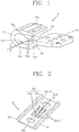
- a stationary contact arm assembly 100 for a molded case circuit breaker may include a current limiting type stationary contact arm 10, a magnet assembly 30, and an elastic support plate 20.
- the current limiting type stationary contact arm 10 has a terminal portion 10b and a contact portion 10a provided at both end portions thereof in the length direction, and has a laid down U-shaped geometric feature in which the contact portion 10a is bent toward the side of the terminal portion 10b.
- the current limiting type stationary contact arm 10 may further include an inclined extension portion 10e, a flat extension portion 10c, and a bent portion 10f.
- the inclined extension portion 10e is provided between the contact portion 10a and the terminal portion 10b and formed to be downwardly extended in an inclined manner from the terminal portion 10b.
- the flat extension portion 10c is a portion forming a space in which the magnet assembly 30 and elastic support plate 20 can be installed between the same and a bottom surface of the contact potion 10a.
- the bent portion 10f is a portion of the current limiting type stationary contact arm 10 formed in a bent shape from the flat extension portion 10c to the contact portion 10a .
- the stationary contact arm assembly 100 for a molded case circuit breaker may be provided in an extended manner from an end portion of the contact portion 10a, and may further include an arc runner 40 for inducing an arc.
- the magnet assembly 30 is a means for enhancing the magnetic permeability to increase an electromagnetic repulsive force between the current limiting type stationary contact arm 10 and the movable contact arm (not shown) during the current limiting operation.
- the magnet assembly 30 may be configured in such a manner that a plurality of steel plates are laminated and fastened by a fastening means such as a rivet.
- the steel plate may be configured with an L-shaped steel plate, for instance.
- the magnet assembly 30 is installed in such a manner that at least part of each steel plate is pushed into the space between the flat extension portion 10c and contact portion 10a of the current limiting type stationary contact arm 10.
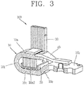
- the elastic support plate 20 is installed in a stationary manner on the flat extension portion 10c of the current limiting type stationary contact arm 10 as illustrated in FIG. 3 , and the elastic support plate 20 has an elastic support portion 20a for supporting the magnet assembly 30 as illustrated in FIG. 3 or 2 .
- the elastic support plate 20 may be formed of a synthetic resin plate, which is so-called plastic, having elasticity, and according to another embodiment, the elastic support plate 20 may be formed of a metal plate such as a thin steel plate having elasticity.
- the flat extension portion 10c of the current limiting type stationary contact arm 10 may include a concave groove portion 10g into which the elastic support portion 20a is inserted as illustrated in FIG. 1 , in correspondence to the elastic support portion 20a.
- the concave groove portion 10g is configured with a groove portion, which is formed with a pair of first inclined surfaces 10g1, and a first flat surface 10g2.
- the pair of first inclined surfaces 10g1 is formed in an inclined manner to be deep toward a central portion in the length direction of the concave groove portion 10g.
- the first flat surface 10g2 is formed with a plane as the most bottom portion in the concave groove portion 10g, which is formed between a pair of first inclined surfaces.
- the elastic support portion 20a may include a plurality of long perforated hole portions 20a1, and a plurality of body portions 20a2 formed between a pair of perforated hole portions 20a1 adjacent to each other.
- the plurality of body portions 20a2 have a pair of second inclined surfaces 20a2-1 formed in an inclined manner to be downwardly convex toward a central portion in the length direction in correspondence to the concave groove portions 10g of the stationary contact arm 10, respectively, and a second flat surface 20a2-2 formed between the pair of second inclined surfaces 20a2-1 to form the most bottom surface in the body portion 20a2.
- the plurality of body portions 20a2 are formed in an inclined manner to be downwardly convex toward a central portion in the length direction, and the downwardly convex height (refer to reference character d2 in FIG. 2 ) of the body portion 20a2 is greater (higher) than the groove depth (refer to reference character d1 in FIG. 1 ) of the concave groove portion 10g.
- reference character d1 represents the groove depth of the concave groove portion 10g
- reference character d2 represents the downwardly convex height (i.e., downwardly protrusion height) of the body portion 20a2.
- the stationary contact arm 10 may include a pair of retaining screw opening portions 10d provided to be protruded in the horizontal direction from both lateral surfaces of the flat extension portion 10c, respectively, to allow the penetration of a retaining screw (not shown) for fixing the stationary contact arm 10 to the molded case circuit breaker, and each of the retaining screw opening portions 10d is provided with a retaining screw opening 10d1.
- the elastic support plate 20 may include a screw through opening portion 20b for allowing the penetration of the retaining screw, and preferably configured with a pair of the screw through opening portions 20b.
- a distance between the pair of screw through opening portions 20b is predetermined as a distance enough to install a lower portion of the magnet assembly 30 therebetween.
- a distance between the pair of screw through opening portions 20b to a forward/backward directional width of the magnet assembly 30 is formed in a sufficiently long manner as much as the predetermined length.
- the screw through opening portion 20b is configured with a long hole portion.
- the elastic support plate 20 has a pair of magnet release prevention wall portions 20c as illustrated in FIG. 2 , and the pair of magnet release prevention wall portion 20c are a portion formed to be extended as much as a predetermined height enough to prevent the transverse directional release of the magnet assembly 30 in the vertically upward direction from both the width directional end portions of the flat elastic support plate 20.
- a distance between the pair of the magnet release prevention wall portions 20c is formed to be less than by a predetermined distance or equal to the width of the magnet assembly 30 as illustrated in FIG. 3 , and thus when the magnet assembly 30 is pushed between the pair of the magnet release prevention wall portions 20c, the pair of the magnet release prevention wall portions 20c becomes open wider to elastically press both the lateral surfaces of the magnet assembly 30, thereby maintaining a coupling state between the magnet assembly 30 and the elastic support plate 20.
- the longitudinal cross-sectional area of the elastic support plate 20 has a U-shape.
- a contact to which reference numeral is not given is attached to the contact portion 10a of the stationary contact arm 10 by welding as illustrated in FIG. 1 .
- the magnet assembly 30 is installed to be pushed into between the magnet release prevention wall portions 20c of the elastic support plate 20, and a lower portion of the magnet assembly 30 is positioned between a pair of screw through opening portions 20b not to obstruct the pair of screw through opening portions 20b.
- a distance between the pair of the magnet release prevention wall portions 20c is formed to be less than by a predetermined distance or equal to the width of the magnet assembly 30 as illustrated in FIG. 3 , and thus when the magnet assembly 30 is pushed between the pair of the magnet release prevention wall portions 20c, the pair of the magnet release prevention wall portions 20c becomes open wider to elastically press both the lateral surfaces of the magnet assembly 30, an as a result, a coupling state between the magnet assembly 30 and the elastic support plate 20 is maintained.
- the downwardly convex height (d2) of the body portion 20a2 is greater (higher) than the groove depth (d1) of the concave groove portion 10g, and thus the body portion 20a2 is compressed by a height difference between the downwardly convex height (d2) of the body portion 20a2 and the groove depth (d1) of the concave groove portion 10g, and if the body portion 20a2 is once mounted on the concave groove portion 10g, then the elastic support plate 20 will be fixed by an elastically repulsive force of the body portion 20a2 that is going to be extended to the original downwardly convex height, thereby preventing the elastic support plate 20 from being released from the stationary contact arm 10.
- the assembled stationary contact arm assembly may pass through the retaining screw opening 10d1 provided at the retaining screw opening portion 10d using a retaining screw (not shown) to be fixed to an enclosure bottom surface of the molded case circuit breaker (not shown) as illustrated in FIG. 1 .
- the retaining screw may be a retaining screw for fixing the stationary contact arm assembly to the molded case circuit breaker, but not a retaining screw for fixing the magnet assembly to the stationary contact arm.
- a stationary contact arm assembly for a molded case circuit breaker may include the elastic support plate 20 having the elastic support portion 20a supporting the magnet assembly 30, and thus a retaining screw for fixing the magnet assembly 30 to the stationary contact arm may be not required to reduce the cost due to the retaining screw, and the process of fastening the retaining screw may be not required to enhance the productivity.
- the stationary contact arm 10 may be provided with the concave groove portion 10g into which the elastic support portion 20a is inserted, thereby allowing the installation of the elastic support plate 20 to be easily completed by inserting the elastic support portion 20a of the elastic support plate 20 into the concave groove portion 10g of the stationary contact arm.
- the elastic support portion 20a may have a configuration in which the elastic support portion 20a includes the plurality of long perforated hole portions 20a1 and a plurality of body portions 20a2 formed between the long perforated hole portions 20a1 and thus the elastic support plate 20 itself supports the magnet assembly 30 by an elastic force, and accordingly, the elastic support plate 20 may support the magnet assembly 30 with its own elastic force with no additional constituent elements such as springs to provide simple constituent components, thereby reducing the production cost as well as facilitating the production process.
- the concave groove portion 10g may be configured with a groove portion formed with a pair of first inclined surfaces 10g1 formed in an inclined manner to be deep toward a central portion in the length direction and a first flat surface 10g2 between the pair of first inclined surfaces 10g1, and the plurality of body portions 20a2 may have a pair of second inclined surfaces 20a2-1 formed in an inclined manner to be downwardly convex toward a central portion in the length direction in correspondence to the concave groove portions 10g, and a second flat surface 20a2-2 between the pair of second inclined surfaces 20a2-1, thereby allowing the second flat surface 20a2-1 and second inclined surface 20a2-1 to be efficiently guided along the first inclined surface 10g1 while installing the elastic support plate 20 on the stationary contact arm 10 as well as allowing the elastic support plate 20 to be securely fixed to the stationary contact arm 10 when the second flat surface 20a2-2 is mounted on the first flat surface 10g2 to prevent the elastic support plate 20 from being released from the stationary
- the downwardly convex height (d2) of the body portion 20a2 may be greater (higher) than the groove depth (d1) of the concave groove portion 10g, and thus the body portion 20a2 may be compressed by a height difference between the downwardly convex height (d2) of the body portion 20a2 and the groove depth (d1) of the concave groove portion 10g, and if the body portion 20a2 is once mounted on the concave groove portion 10g, then the elastic support plate 20 will be fixed by an elastically repulsive force of the body portion 20a2 that is going to be extended to the original downwardly convex height, thereby preventing the elastic support plate 20 from being released from the stationary contact arm 10.
- the stationary contact arm 10 may include a pair of retaining screw opening portions 10d provided to be protruded in the horizontal direction from both lateral surfaces of the flat extension portion 10c, respectively, to allow the penetration of a retaining screw for fixing it to the molded case circuit breaker, and the elastic support plate 20 may include a screw through opening portion 20b for allowing the penetration of the retaining screw, and thus the retaining screw may be fixed to an enclosure bottom surface of the molded case circuit breaker the retaining screw opening 10d1 of the retaining screw opening portion 10d and the screw through opening portion 20b, thereby obtaining an effect of allowing the stationary contact arm 10 to be positionally fixed thereto in a secure manner.
- the screw through opening portion 20b may be configured with a long hole portion, thereby allowing the penetration of a retaining screw in a flexible manner within the length of the long hole even when the retaining screw opening portion 10d and screw through opening portion 20b are not formed on a straight line.
Landscapes
- Physics & Mathematics (AREA)
- Electromagnetism (AREA)
- Breakers (AREA)
Claims (8)
- Ensemble bras de contact fixe pour un disjoncteur à boîtier moulé, l'ensemble bras de contact fixe (100) comprenant :un bras de contact fixe (10) de type limiteur de courant ayant une partie terminale (10b) et une partie de contact (10a) fournies aux deux parties d'extrémité de celui-ci dans la direction en longueur, et une partie d'extension inclinée (10e) fournie entre la partie de contact (10a) et la partie terminale (10b) et formée de manière à s'étendre vers le bas de façon inclinée à partir de la partie terminale (10b), une partie d'extension plate (10c) formant un espace entre la partie d'extension plate (10c) et une surface inférieure de la partie de contact (10a), et une partie courbe (10f) formée avec une forme courbe depuis la partie d'extension plate (10c) jusqu'à la partie de contact (10a), et dans lequel la partie d'extension inclinée (10e) est fournie entre la partie d'extension plate (10c) et la partie terminale (10b) ;un ensemble d'aimant (30) ayant une pluralité de plaques d'acier dont au moins une partie est mise en place pour être poussée dans l'espace entre la partie d'extension plate (10c) et la partie de contact (10a) dans le bras de contact fixe (10) pour améliorer la perméabilité magnétique de manière à augmenter une force de répulsion électromagnétique pendant l'opération de limitation de courant ;caractérisé en ce qu'il comprend en outre une plaque de support élastique (20) ayant une partie de support élastique (20a) mise en place sur la partie d'extension plate (10c) du bras de contact fixe (10) pour supporter l'ensemble d'aimant (30),dans lequel la partie d'extension plate (10c) du bras de contact fixe (10) est dotée d'une partie de rainure concave (10g) dans laquelle la partie de support élastique (20a) est insérée.
- Ensemble bras de contact fixe pour un disjoncteur à boîtier moulé selon la revendication 1, dans lequel la partie de supporté élastique (20a) comprend :une pluralité de parties à trous perforés oblongs (20a1) ; etune pluralité de parties de corps (20a2) formées entre les parties à trous perforés (20a1).
- Ensemble bras de contact fixe pour un disjoncteur à boîtier moulé selon la revendication 1, dans lequel la partie de rainure concave (10g) est configurée avec une partie de rainure formée avec une paire de premières surfaces inclinées (10g1) formées d'une manière inclinée pour être en profondeur vers une partie centrale dans la direction en longueur et une première surface plate (10g2) entre la paire de premières surfaces inclinées (10g1), et
la partie de support élastique (20a) a une pluralité de parties de corps (20a2) ayant une paire de deuxièmes surfaces inclinées (20a2-1) formées d'une manière inclinée pour être convexes vers le bas vers une partie centrale dans la direction en longueur, respectivement en correspondance avec la partie de rainure concave (10g), et une deuxième surface plate (20a2-2) entre la paire de deuxièmes surfaces inclinées (20a2-1). - Ensemble bras de contact fixe pour un disjoncteur à boîtier moulé selon l'une quelconque des revendications 1 ou 3,
dans lequel la partie de support élastique (20a) comprend :une pluralité de parties à trous perforés oblongs (20a1) ; etune pluralité de parties de corps (20a2) formées entre les parties à trous perforés (20a1),dans lequel la pluralité de parties de corps (20a2) sont formées d'une manière inclinée pour être convexes vers le bas vers une partie centrale dans la direction en longueur, etla hauteur convexe vers le bas (d2) de la partie de corps (20a2) est supérieure à la profondeur de rainure (d1) de la partie de rainure concave (10g). - Ensemble bras de contact fixe pour un disjoncteur à boîtier moulé selon l'une quelconque des revendications 1-4, dans lequel le bras de contact fixe (10) comprend une paire de parties d'ouverture de vis de fixation (10d) fournies pour être respectivement en saillie dans la direction horizontale à partir des deux surfaces latérales de la partie d'extension plate (10c) pour permettre la pénétration d'une vis de fixation pour la fixer au disjoncteur à boîtier moulé, et
la plaque de support élastique (20) comprend une partie d'ouverture traversante de vis (20b) pour permettre la pénétration de la vis de fixation. - Ensemble bras de contact fixe pour un disjoncteur à boîtier moulé selon la revendication 5, dans lequel la partie d'ouverture traversante de vis (20b) est configurée avec une partie à trou oblong.
- Ensemble bras de contact fixe pour un disjoncteur à boîtier moulé selon l'une quelconque des revendications 1-6, dans lequel la partie de support élastique (20a) comprend en outre une paire de parties de paroi de prévention de libération d'aimant (20c) formées de manière à s'étendre aussi loin qu'une hauteur prédéterminée suffisante pour empêcher la libération en direction transversale de l'ensemble d'aimant (30) dans la direction verticalement vers le haut depuis les deux parties d'extrémité en direction en largeur de la plaque de support élastique (20).
- Ensemble bras de contact fixe pour un disjoncteur à boîtier moulé selon la revendication 7, dans lequel une distance entre la paire de parties de paroi de prévention de libération d'aimant (20c) est formée pour être de moins de l'ordre d'une distance prédéterminée ou égale à la largeur de l'ensemble d'aimant (30).
Applications Claiming Priority (1)
| Application Number | Priority Date | Filing Date | Title |
|---|---|---|---|
| KR1020120100610A KR101323605B1 (ko) | 2012-09-11 | 2012-09-11 | 배선용 회로차단기용 고정접촉자 어셈블리 |
Publications (3)
| Publication Number | Publication Date |
|---|---|
| EP2706552A2 EP2706552A2 (fr) | 2014-03-12 |
| EP2706552A3 EP2706552A3 (fr) | 2016-02-17 |
| EP2706552B1 true EP2706552B1 (fr) | 2018-01-10 |
Family
ID=49084934
Family Applications (1)
| Application Number | Title | Priority Date | Filing Date |
|---|---|---|---|
| EP13183128.1A Not-in-force EP2706552B1 (fr) | 2012-09-11 | 2013-09-05 | Ensemble bras de contact fixe pour disjoncteur à boîtier moulé |
Country Status (6)
| Country | Link |
|---|---|
| US (1) | US8884728B2 (fr) |
| EP (1) | EP2706552B1 (fr) |
| KR (1) | KR101323605B1 (fr) |
| CN (1) | CN103681122B (fr) |
| BR (1) | BR102013023179A2 (fr) |
| ES (1) | ES2664323T3 (fr) |
Families Citing this family (7)
| Publication number | Priority date | Publication date | Assignee | Title |
|---|---|---|---|---|
| US9767980B2 (en) * | 2015-10-28 | 2017-09-19 | Eaton Corporation | Electrical switching apparatus, and slot motor and enclosure therefor |
| CN107799368B (zh) * | 2017-11-17 | 2020-01-10 | 河南森源电气股份有限公司 | 塑壳断路器触头结构 |
| CN111180288A (zh) * | 2018-11-13 | 2020-05-19 | 上海良信电器股份有限公司 | 灭弧装置及设有该灭弧装置的断路器 |
| WO2022234989A1 (fr) * | 2021-05-06 | 2022-11-10 | 엘에스일렉트릭 주식회사 | Unité de disjoncteur et disjoncteur à air la comprenant |
| JP2023156772A (ja) * | 2022-04-13 | 2023-10-25 | オムロン株式会社 | 電磁継電器 |
| KR102851384B1 (ko) * | 2023-09-07 | 2025-08-26 | 에이치디현대일렉트릭 주식회사 | 소전류 차단기능이 마련된 저압직류차단기 |
| KR102725409B1 (ko) * | 2024-05-03 | 2024-11-04 | 주식회사 이엔에스 | 배선용 차단기의 플러그인 커넥터 |
Family Cites Families (16)
| Publication number | Priority date | Publication date | Assignee | Title |
|---|---|---|---|---|
| CA1245698A (fr) * | 1983-06-02 | 1988-11-29 | Gregory T. Divincenzo | Disjoncteur concu pour une fabrication acceleree |
| US4698903A (en) * | 1985-04-01 | 1987-10-13 | General Electric Company | Circuit breaker highspeed assembly |
| US4654491A (en) * | 1986-03-03 | 1987-03-31 | Westinghouse Electric Corp. | Circuit breaker with contact support and arc runner |
| JP2809652B2 (ja) * | 1988-11-12 | 1998-10-15 | 株式会社東芝 | 回路遮断器 |
| US5268661A (en) * | 1992-09-18 | 1993-12-07 | Westinghouse Electric Corp. | Current throttle technique |
| US5589672A (en) * | 1994-06-14 | 1996-12-31 | Fuji Electric Co., Ltd. | Circuit breaker with arc quenching device and vent |
| US5694098A (en) * | 1996-05-20 | 1997-12-02 | Eaton Corporation | Rate of current rise sensitive slot motor and switching apparatus having current limiting contact arrangement incorporating said slot motor |
| KR19980054546U (ko) * | 1996-12-31 | 1998-10-07 | 이종수 | 한류형 배선용 차단기 |
| JP2000357428A (ja) | 1999-06-11 | 2000-12-26 | Hitachi Ltd | 回路遮断器 |
| US6300586B1 (en) * | 1999-12-09 | 2001-10-09 | General Electric Company | Arc runner retaining feature |
| US6281459B1 (en) | 2000-04-21 | 2001-08-28 | Eaton Corporation | Circuit interrupter having an improved slot motor assembly |
| US7488915B2 (en) * | 2006-09-20 | 2009-02-10 | Eaton Corporation | ARC baffle, and ARC chute assembly and electrical switching apparatus employing the same |
| US7551050B2 (en) * | 2006-09-22 | 2009-06-23 | Rockwell Automation Technologies, Inc. | Contactor assembly with arc steering system |
| US7358840B1 (en) * | 2006-09-28 | 2008-04-15 | Eaton Corporation | Electrical switching apparatus including a split core slot motor and method of installing a slot motor assembly in a circuit interrupter |
| US7532097B2 (en) * | 2007-02-12 | 2009-05-12 | Eaton Corporation | Slot motor housing and circuit interrupter including the same |
| KR101076286B1 (ko) | 2011-02-07 | 2011-10-26 | 주식회사 대륙 | 슬롯 모터가 구비된 회로 차단기 |
-
2012
- 2012-09-11 KR KR1020120100610A patent/KR101323605B1/ko not_active Expired - Fee Related
-
2013
- 2013-09-04 US US14/017,912 patent/US8884728B2/en not_active Expired - Fee Related
- 2013-09-05 ES ES13183128.1T patent/ES2664323T3/es active Active
- 2013-09-05 EP EP13183128.1A patent/EP2706552B1/fr not_active Not-in-force
- 2013-09-10 BR BR102013023179A patent/BR102013023179A2/pt active Search and Examination
- 2013-09-11 CN CN201310413026.4A patent/CN103681122B/zh not_active Expired - Fee Related
Non-Patent Citations (1)
| Title |
|---|
| None * |
Also Published As
| Publication number | Publication date |
|---|---|
| KR101323605B1 (ko) | 2013-11-01 |
| EP2706552A2 (fr) | 2014-03-12 |
| BR102013023179A2 (pt) | 2017-05-09 |
| US20140070908A1 (en) | 2014-03-13 |
| CN103681122A (zh) | 2014-03-26 |
| US8884728B2 (en) | 2014-11-11 |
| CN103681122B (zh) | 2015-11-18 |
| ES2664323T3 (es) | 2018-04-19 |
| EP2706552A3 (fr) | 2016-02-17 |
Similar Documents
| Publication | Publication Date | Title |
|---|---|---|
| EP2706552B1 (fr) | Ensemble bras de contact fixe pour disjoncteur à boîtier moulé | |
| EP2919248B1 (fr) | Relais électromagnétique | |
| JP4466209B2 (ja) | 回路遮断器 | |
| KR102830557B1 (ko) | 전자 계전기 | |
| EP2945175B1 (fr) | Dispositif de contact | |
| CN106716588A (zh) | 电磁继电器 | |
| EP3557600B1 (fr) | Ensemble de contact fixe et contact de commutateur correspondant | |
| US9196433B2 (en) | Electromagnetic switch | |
| EP2975625A1 (fr) | Relais | |
| US10361042B2 (en) | Removable switching element for an electrical switching device and switching device for switching an electric current comprising such a removable element | |
| EP3266029B1 (fr) | Dispositif d'interrupteur d'isolement à fusibles compact haute tension ayant un ensemble de déviation d'arc magnétique | |
| FI82787B (fi) | Elektrisk omkopplingsanordning. | |
| KR200476957Y1 (ko) | 전자접촉기 | |
| EP3561848B1 (fr) | Contacteur | |
| KR101232453B1 (ko) | 회로차단기 | |
| CN107533930A (zh) | 具有灭弧装置的开关设备 | |
| KR880001427Y1 (ko) | 전자(電磁)개폐장치 | |
| JP5492649B2 (ja) | 回路遮断器 | |
| KR20120136256A (ko) | 전자 접촉기 | |
| US9412540B2 (en) | Switch | |
| KR100510714B1 (ko) | 차단기의 트립기구부 구조 | |
| KR101922154B1 (ko) | 전자접촉기 | |
| JP2002260475A (ja) | 開閉装置 | |
| KR20170072067A (ko) | 전자접촉기의 고정접촉자 조립 구조 | |
| CN116615794A (zh) | 断路器、配电盘和电弧行走板 |
Legal Events
| Date | Code | Title | Description |
|---|---|---|---|
| PUAI | Public reference made under article 153(3) epc to a published international application that has entered the european phase |
Free format text: ORIGINAL CODE: 0009012 |
|
| AK | Designated contracting states |
Kind code of ref document: A2 Designated state(s): AL AT BE BG CH CY CZ DE DK EE ES FI FR GB GR HR HU IE IS IT LI LT LU LV MC MK MT NL NO PL PT RO RS SE SI SK SM TR |
|
| AX | Request for extension of the european patent |
Extension state: BA ME |
|
| PUAL | Search report despatched |
Free format text: ORIGINAL CODE: 0009013 |
|
| AK | Designated contracting states |
Kind code of ref document: A3 Designated state(s): AL AT BE BG CH CY CZ DE DK EE ES FI FR GB GR HR HU IE IS IT LI LT LU LV MC MK MT NL NO PL PT RO RS SE SI SK SM TR |
|
| AX | Request for extension of the european patent |
Extension state: BA ME |
|
| RIC1 | Information provided on ipc code assigned before grant |
Ipc: H01H 77/10 20060101ALI20160112BHEP Ipc: H01H 71/02 20060101AFI20160112BHEP |
|
| 17P | Request for examination filed |
Effective date: 20160817 |
|
| RBV | Designated contracting states (corrected) |
Designated state(s): AL AT BE BG CH CY CZ DE DK EE ES FI FR GB GR HR HU IE IS IT LI LT LU LV MC MK MT NL NO PL PT RO RS SE SI SK SM TR |
|
| GRAP | Despatch of communication of intention to grant a patent |
Free format text: ORIGINAL CODE: EPIDOSNIGR1 |
|
| STAA | Information on the status of an ep patent application or granted ep patent |
Free format text: STATUS: GRANT OF PATENT IS INTENDED |
|
| INTG | Intention to grant announced |
Effective date: 20170822 |
|
| GRAS | Grant fee paid |
Free format text: ORIGINAL CODE: EPIDOSNIGR3 |
|
| GRAA | (expected) grant |
Free format text: ORIGINAL CODE: 0009210 |
|
| STAA | Information on the status of an ep patent application or granted ep patent |
Free format text: STATUS: THE PATENT HAS BEEN GRANTED |
|
| AK | Designated contracting states |
Kind code of ref document: B1 Designated state(s): AL AT BE BG CH CY CZ DE DK EE ES FI FR GB GR HR HU IE IS IT LI LT LU LV MC MK MT NL NO PL PT RO RS SE SI SK SM TR |
|
| REG | Reference to a national code |
Ref country code: CH Ref legal event code: EP Ref country code: AT Ref legal event code: REF Ref document number: 963270 Country of ref document: AT Kind code of ref document: T Effective date: 20180115 |
|
| REG | Reference to a national code |
Ref country code: IE Ref legal event code: FG4D |
|
| REG | Reference to a national code |
Ref country code: DE Ref legal event code: R096 Ref document number: 602013031883 Country of ref document: DE |
|
| REG | Reference to a national code |
Ref country code: ES Ref legal event code: FG2A Ref document number: 2664323 Country of ref document: ES Kind code of ref document: T3 Effective date: 20180419 |
|
| REG | Reference to a national code |
Ref country code: NL Ref legal event code: MP Effective date: 20180110 |
|
| REG | Reference to a national code |
Ref country code: FR Ref legal event code: PLFP Year of fee payment: 6 |
|
| REG | Reference to a national code |
Ref country code: AT Ref legal event code: MK05 Ref document number: 963270 Country of ref document: AT Kind code of ref document: T Effective date: 20180110 |
|
| PG25 | Lapsed in a contracting state [announced via postgrant information from national office to epo] |
Ref country code: NL Free format text: LAPSE BECAUSE OF FAILURE TO SUBMIT A TRANSLATION OF THE DESCRIPTION OR TO PAY THE FEE WITHIN THE PRESCRIBED TIME-LIMIT Effective date: 20180110 |
|
| PG25 | Lapsed in a contracting state [announced via postgrant information from national office to epo] |
Ref country code: HR Free format text: LAPSE BECAUSE OF FAILURE TO SUBMIT A TRANSLATION OF THE DESCRIPTION OR TO PAY THE FEE WITHIN THE PRESCRIBED TIME-LIMIT Effective date: 20180110 Ref country code: LT Free format text: LAPSE BECAUSE OF FAILURE TO SUBMIT A TRANSLATION OF THE DESCRIPTION OR TO PAY THE FEE WITHIN THE PRESCRIBED TIME-LIMIT Effective date: 20180110 Ref country code: NO Free format text: LAPSE BECAUSE OF FAILURE TO SUBMIT A TRANSLATION OF THE DESCRIPTION OR TO PAY THE FEE WITHIN THE PRESCRIBED TIME-LIMIT Effective date: 20180410 Ref country code: FI Free format text: LAPSE BECAUSE OF FAILURE TO SUBMIT A TRANSLATION OF THE DESCRIPTION OR TO PAY THE FEE WITHIN THE PRESCRIBED TIME-LIMIT Effective date: 20180110 Ref country code: CY Free format text: LAPSE BECAUSE OF FAILURE TO SUBMIT A TRANSLATION OF THE DESCRIPTION OR TO PAY THE FEE WITHIN THE PRESCRIBED TIME-LIMIT Effective date: 20180110 |
|
| PG25 | Lapsed in a contracting state [announced via postgrant information from national office to epo] |
Ref country code: LV Free format text: LAPSE BECAUSE OF FAILURE TO SUBMIT A TRANSLATION OF THE DESCRIPTION OR TO PAY THE FEE WITHIN THE PRESCRIBED TIME-LIMIT Effective date: 20180110 Ref country code: SE Free format text: LAPSE BECAUSE OF FAILURE TO SUBMIT A TRANSLATION OF THE DESCRIPTION OR TO PAY THE FEE WITHIN THE PRESCRIBED TIME-LIMIT Effective date: 20180110 Ref country code: IS Free format text: LAPSE BECAUSE OF FAILURE TO SUBMIT A TRANSLATION OF THE DESCRIPTION OR TO PAY THE FEE WITHIN THE PRESCRIBED TIME-LIMIT Effective date: 20180510 Ref country code: PL Free format text: LAPSE BECAUSE OF FAILURE TO SUBMIT A TRANSLATION OF THE DESCRIPTION OR TO PAY THE FEE WITHIN THE PRESCRIBED TIME-LIMIT Effective date: 20180110 Ref country code: GR Free format text: LAPSE BECAUSE OF FAILURE TO SUBMIT A TRANSLATION OF THE DESCRIPTION OR TO PAY THE FEE WITHIN THE PRESCRIBED TIME-LIMIT Effective date: 20180411 Ref country code: AT Free format text: LAPSE BECAUSE OF FAILURE TO SUBMIT A TRANSLATION OF THE DESCRIPTION OR TO PAY THE FEE WITHIN THE PRESCRIBED TIME-LIMIT Effective date: 20180110 Ref country code: RS Free format text: LAPSE BECAUSE OF FAILURE TO SUBMIT A TRANSLATION OF THE DESCRIPTION OR TO PAY THE FEE WITHIN THE PRESCRIBED TIME-LIMIT Effective date: 20180110 Ref country code: BG Free format text: LAPSE BECAUSE OF FAILURE TO SUBMIT A TRANSLATION OF THE DESCRIPTION OR TO PAY THE FEE WITHIN THE PRESCRIBED TIME-LIMIT Effective date: 20180410 |
|
| REG | Reference to a national code |
Ref country code: DE Ref legal event code: R097 Ref document number: 602013031883 Country of ref document: DE |
|
| PG25 | Lapsed in a contracting state [announced via postgrant information from national office to epo] |
Ref country code: AL Free format text: LAPSE BECAUSE OF FAILURE TO SUBMIT A TRANSLATION OF THE DESCRIPTION OR TO PAY THE FEE WITHIN THE PRESCRIBED TIME-LIMIT Effective date: 20180110 Ref country code: EE Free format text: LAPSE BECAUSE OF FAILURE TO SUBMIT A TRANSLATION OF THE DESCRIPTION OR TO PAY THE FEE WITHIN THE PRESCRIBED TIME-LIMIT Effective date: 20180110 Ref country code: RO Free format text: LAPSE BECAUSE OF FAILURE TO SUBMIT A TRANSLATION OF THE DESCRIPTION OR TO PAY THE FEE WITHIN THE PRESCRIBED TIME-LIMIT Effective date: 20180110 |
|
| PLBE | No opposition filed within time limit |
Free format text: ORIGINAL CODE: 0009261 |
|
| STAA | Information on the status of an ep patent application or granted ep patent |
Free format text: STATUS: NO OPPOSITION FILED WITHIN TIME LIMIT |
|
| PG25 | Lapsed in a contracting state [announced via postgrant information from national office to epo] |
Ref country code: DK Free format text: LAPSE BECAUSE OF FAILURE TO SUBMIT A TRANSLATION OF THE DESCRIPTION OR TO PAY THE FEE WITHIN THE PRESCRIBED TIME-LIMIT Effective date: 20180110 Ref country code: SM Free format text: LAPSE BECAUSE OF FAILURE TO SUBMIT A TRANSLATION OF THE DESCRIPTION OR TO PAY THE FEE WITHIN THE PRESCRIBED TIME-LIMIT Effective date: 20180110 Ref country code: CZ Free format text: LAPSE BECAUSE OF FAILURE TO SUBMIT A TRANSLATION OF THE DESCRIPTION OR TO PAY THE FEE WITHIN THE PRESCRIBED TIME-LIMIT Effective date: 20180110 Ref country code: SK Free format text: LAPSE BECAUSE OF FAILURE TO SUBMIT A TRANSLATION OF THE DESCRIPTION OR TO PAY THE FEE WITHIN THE PRESCRIBED TIME-LIMIT Effective date: 20180110 |
|
| 26N | No opposition filed |
Effective date: 20181011 |
|
| PG25 | Lapsed in a contracting state [announced via postgrant information from national office to epo] |
Ref country code: SI Free format text: LAPSE BECAUSE OF FAILURE TO SUBMIT A TRANSLATION OF THE DESCRIPTION OR TO PAY THE FEE WITHIN THE PRESCRIBED TIME-LIMIT Effective date: 20180110 |
|
| PG25 | Lapsed in a contracting state [announced via postgrant information from national office to epo] |
Ref country code: MC Free format text: LAPSE BECAUSE OF FAILURE TO SUBMIT A TRANSLATION OF THE DESCRIPTION OR TO PAY THE FEE WITHIN THE PRESCRIBED TIME-LIMIT Effective date: 20180110 |
|
| REG | Reference to a national code |
Ref country code: CH Ref legal event code: PL |
|
| REG | Reference to a national code |
Ref country code: BE Ref legal event code: MM Effective date: 20180930 |
|
| REG | Reference to a national code |
Ref country code: IE Ref legal event code: MM4A |
|
| PG25 | Lapsed in a contracting state [announced via postgrant information from national office to epo] |
Ref country code: LU Free format text: LAPSE BECAUSE OF NON-PAYMENT OF DUE FEES Effective date: 20180905 |
|
| PG25 | Lapsed in a contracting state [announced via postgrant information from national office to epo] |
Ref country code: IE Free format text: LAPSE BECAUSE OF NON-PAYMENT OF DUE FEES Effective date: 20180905 |
|
| PG25 | Lapsed in a contracting state [announced via postgrant information from national office to epo] |
Ref country code: LI Free format text: LAPSE BECAUSE OF NON-PAYMENT OF DUE FEES Effective date: 20180930 Ref country code: CH Free format text: LAPSE BECAUSE OF NON-PAYMENT OF DUE FEES Effective date: 20180930 Ref country code: BE Free format text: LAPSE BECAUSE OF NON-PAYMENT OF DUE FEES Effective date: 20180930 |
|
| PG25 | Lapsed in a contracting state [announced via postgrant information from national office to epo] |
Ref country code: MT Free format text: LAPSE BECAUSE OF NON-PAYMENT OF DUE FEES Effective date: 20180905 |
|
| PG25 | Lapsed in a contracting state [announced via postgrant information from national office to epo] |
Ref country code: TR Free format text: LAPSE BECAUSE OF FAILURE TO SUBMIT A TRANSLATION OF THE DESCRIPTION OR TO PAY THE FEE WITHIN THE PRESCRIBED TIME-LIMIT Effective date: 20180110 |
|
| PG25 | Lapsed in a contracting state [announced via postgrant information from national office to epo] |
Ref country code: HU Free format text: LAPSE BECAUSE OF FAILURE TO SUBMIT A TRANSLATION OF THE DESCRIPTION OR TO PAY THE FEE WITHIN THE PRESCRIBED TIME-LIMIT; INVALID AB INITIO Effective date: 20130905 Ref country code: PT Free format text: LAPSE BECAUSE OF FAILURE TO SUBMIT A TRANSLATION OF THE DESCRIPTION OR TO PAY THE FEE WITHIN THE PRESCRIBED TIME-LIMIT Effective date: 20180110 |
|
| PG25 | Lapsed in a contracting state [announced via postgrant information from national office to epo] |
Ref country code: MK Free format text: LAPSE BECAUSE OF NON-PAYMENT OF DUE FEES Effective date: 20180110 |
|
| PGFP | Annual fee paid to national office [announced via postgrant information from national office to epo] |
Ref country code: FR Payment date: 20200609 Year of fee payment: 8 |
|
| PGFP | Annual fee paid to national office [announced via postgrant information from national office to epo] |
Ref country code: DE Payment date: 20200605 Year of fee payment: 8 Ref country code: GB Payment date: 20200709 Year of fee payment: 8 |
|
| PGFP | Annual fee paid to national office [announced via postgrant information from national office to epo] |
Ref country code: IT Payment date: 20200914 Year of fee payment: 8 |
|
| PGFP | Annual fee paid to national office [announced via postgrant information from national office to epo] |
Ref country code: ES Payment date: 20201008 Year of fee payment: 8 |
|
| REG | Reference to a national code |
Ref country code: DE Ref legal event code: R119 Ref document number: 602013031883 Country of ref document: DE |
|
| GBPC | Gb: european patent ceased through non-payment of renewal fee |
Effective date: 20210905 |
|
| PG25 | Lapsed in a contracting state [announced via postgrant information from national office to epo] |
Ref country code: GB Free format text: LAPSE BECAUSE OF NON-PAYMENT OF DUE FEES Effective date: 20210905 Ref country code: FR Free format text: LAPSE BECAUSE OF NON-PAYMENT OF DUE FEES Effective date: 20210930 Ref country code: DE Free format text: LAPSE BECAUSE OF NON-PAYMENT OF DUE FEES Effective date: 20220401 |
|
| PG25 | Lapsed in a contracting state [announced via postgrant information from national office to epo] |
Ref country code: IT Free format text: LAPSE BECAUSE OF NON-PAYMENT OF DUE FEES Effective date: 20210905 |
|
| REG | Reference to a national code |
Ref country code: ES Ref legal event code: FD2A Effective date: 20221107 |
|
| PG25 | Lapsed in a contracting state [announced via postgrant information from national office to epo] |
Ref country code: ES Free format text: LAPSE BECAUSE OF NON-PAYMENT OF DUE FEES Effective date: 20210906 |