EP2704812B1 - Filtervorrichtung - Google Patents
Filtervorrichtung Download PDFInfo
- Publication number
- EP2704812B1 EP2704812B1 EP12724887.0A EP12724887A EP2704812B1 EP 2704812 B1 EP2704812 B1 EP 2704812B1 EP 12724887 A EP12724887 A EP 12724887A EP 2704812 B1 EP2704812 B1 EP 2704812B1
- Authority
- EP
- European Patent Office
- Prior art keywords
- chamber
- flushing
- fluid
- hydraulic accumulator
- filtering
- Prior art date
- Legal status (The legal status is an assumption and is not a legal conclusion. Google has not performed a legal analysis and makes no representation as to the accuracy of the status listed.)
- Active
Links
Images




Classifications
-
- B—PERFORMING OPERATIONS; TRANSPORTING
- B01—PHYSICAL OR CHEMICAL PROCESSES OR APPARATUS IN GENERAL
- B01D—SEPARATION
- B01D29/00—Filters with filtering elements stationary during filtration, e.g. pressure or suction filters, not covered by groups B01D24/00 - B01D27/00; Filtering elements therefor
- B01D29/62—Regenerating the filter material in the filter
- B01D29/66—Regenerating the filter material in the filter by flushing, e.g. counter-current air-bumps
- B01D29/665—Regenerating the filter material in the filter by flushing, e.g. counter-current air-bumps by using pistons
-
- B—PERFORMING OPERATIONS; TRANSPORTING
- B01—PHYSICAL OR CHEMICAL PROCESSES OR APPARATUS IN GENERAL
- B01D—SEPARATION
- B01D29/00—Filters with filtering elements stationary during filtration, e.g. pressure or suction filters, not covered by groups B01D24/00 - B01D27/00; Filtering elements therefor
- B01D29/50—Filters with filtering elements stationary during filtration, e.g. pressure or suction filters, not covered by groups B01D24/00 - B01D27/00; Filtering elements therefor with multiple filtering elements, characterised by their mutual disposition
- B01D29/52—Filters with filtering elements stationary during filtration, e.g. pressure or suction filters, not covered by groups B01D24/00 - B01D27/00; Filtering elements therefor with multiple filtering elements, characterised by their mutual disposition in parallel connection
-
- B—PERFORMING OPERATIONS; TRANSPORTING
- B01—PHYSICAL OR CHEMICAL PROCESSES OR APPARATUS IN GENERAL
- B01D—SEPARATION
- B01D29/00—Filters with filtering elements stationary during filtration, e.g. pressure or suction filters, not covered by groups B01D24/00 - B01D27/00; Filtering elements therefor
- B01D29/62—Regenerating the filter material in the filter
- B01D29/66—Regenerating the filter material in the filter by flushing, e.g. counter-current air-bumps
-
- B—PERFORMING OPERATIONS; TRANSPORTING
- B01—PHYSICAL OR CHEMICAL PROCESSES OR APPARATUS IN GENERAL
- B01D—SEPARATION
- B01D29/00—Filters with filtering elements stationary during filtration, e.g. pressure or suction filters, not covered by groups B01D24/00 - B01D27/00; Filtering elements therefor
- B01D29/62—Regenerating the filter material in the filter
- B01D29/66—Regenerating the filter material in the filter by flushing, e.g. counter-current air-bumps
- B01D29/668—Regenerating the filter material in the filter by flushing, e.g. counter-current air-bumps with valves, e.g. rotating valves for coaxially placed filtering elements
-
- B—PERFORMING OPERATIONS; TRANSPORTING
- B01—PHYSICAL OR CHEMICAL PROCESSES OR APPARATUS IN GENERAL
- B01D—SEPARATION
- B01D29/00—Filters with filtering elements stationary during filtration, e.g. pressure or suction filters, not covered by groups B01D24/00 - B01D27/00; Filtering elements therefor
- B01D29/62—Regenerating the filter material in the filter
- B01D29/66—Regenerating the filter material in the filter by flushing, e.g. counter-current air-bumps
- B01D29/68—Regenerating the filter material in the filter by flushing, e.g. counter-current air-bumps with backwash arms, shoes or nozzles
Definitions
- the invention relates to a filter device having the features in the preamble of claim 1.
- An in DE 10 2007 054 737 A1 discloses a continuous filtration operation, wherein successively filter elements to be regenerated, are backwashed, while the filtration is continued over the remaining filter elements, so that the filtration operation is interrupted at any time.
- the backwashing does not take place exclusively in such a way that the system pressure prevailing in the filter device allows a partial flow of the filtrate to flow through the filter element to be cleaned in the reverse direction in order to detach and remove the dirt from the element, but that in an effort to be able to remove more stubborn dirt, a negative pressure is generated by means of a pressure control device on each filter element to be backflushed. Therefore, not only the system pressure is effective for the backwashing, but there is a higher pressure gradient under the action of the pressure control to remove dirt.
- the pressure control device has a shut-off element, by means of which the fluid connection between the fluid flowing into the filter housing and the respective filter element to be backwashed can be blocked for a respective backwashing process.
- a shut-off element by means of which the fluid connection between the fluid flowing into the filter housing and the respective filter element to be backwashed can be blocked for a respective backwashing process.
- a genus same to the invention filter device is in the DE 40 30 084 A1 disclosed.
- the known filter device comprises a plurality of filter elements, which are accommodated in a filter housing with a filter inlet for fluid to be filtered and a filter outlet for the filtered fluid, wherein during the filtration process at least one of the filter elements for cleaning its effective filter surface by means of a backwashing device is backwashed , which includes a pressure control device for assisting the backwashing, wherein the pressure control device includes a hydraulic accumulator whose one fluid chamber during the filtration process with an amount of cleaned fluid fillable and for a backwash process via a backwash guide with the clean side the at least one filter element to be cleaned off can be connected, and wherein a further fluid chamber of the hydraulic accumulator for a backwashing process can be acted upon with a media pressure to at least partially dispense the filling quantity of the cleaned fluid for the backwashing process from the first fluid chamber by a movement of a separating element of the hydraulic accumul
- the invention has the object to provide a filter device available, in which a supported by pressure control, particularly effective backwashing effect can be achieved.
- the throttle device is located between a filtrate part of a main chamber of the filter housing and an inflow line of the backwash guide. This ensures that the filling process takes place in each case without a possible drop in the system pressure with a corresponding reduction in the volume flow of the filtrate discharged from the device occurring due to a larger, diverted volume flow.
- the pressure control device includes a hydraulic accumulator whose fluid chamber, while the device is operating in filtration mode, can be filled with a quantity of cleaned fluid and can be connected to the clean side of the respective filter element to be cleaned for a backwashing process via a backwash guide.
- a hydraulic accumulator whose fluid chamber, while the device is operating in filtration mode, can be filled with a quantity of cleaned fluid and can be connected to the clean side of the respective filter element to be cleaned for a backwashing process via a backwash guide.
- the flow rate of the flushing liquid reaching the filter element via the backwash guide can be optimally adapted to the conditions, i. to be chosen so that the best possible flushing effect is achieved in adaptation to the type of filter medium.
- relatively pressure-resistant filter elements such as conical or cylindrical Spaltsiebrohrettin, can be used in the hydraulic accumulator with high pressure level and thus high flow rates, whereby even stubborn dirt are safely removed from the filter surface.
- a medium pressure source in particular in the form of a compressed gas source
- the use of compressed air may be particularly advantageous, for example, when the filter device is operated in conjunction with plants or facilities in which a compressed air supply is present. It is understood that other gaseous media, gas-alcohol mixtures or fluid-solid mixtures could be provided as print media. Also, seawater could be used as a pressurized medium under deep water pressure, especially in subsea installations such as deepwater wells.
- hydraulic accumulator and backwash guide are connected to each other, rotatably arranged in the filter housing and movable for adjusting movements between filtration operation and backwashing by means of a rotary drive.
- a rotary drive at a free and easily accessible end of the hydraulic accumulator, preferably in the form of an electric geared motor, is mounted, which transmits the rotational movement via the hydraulic accumulator on the further located inside the device backwash guide and adjusts them in the rotational positions in which the fluid connection is formed to be cleaned filter element.
- a hydraulic accumulator a piston accumulator which is rotatable about the cylinder axis together with the arranged at a cylinder end backwash.
- the piston accumulator is characterized by a particularly robust design by a good ratio between size and Aufrismer filling amount of purified fluid, the total displacement of the piston and thus approximately the total volume of Memory cylinder corresponds.
- the filter elements can be accommodated in each case in its own element chamber, which are arranged in the filter housing on a circular axis surrounding the cylinder axis concentric.
- the connection connection of the individual element chambers with the rotatable backflushing can be made particularly simple.
- the arrangement may be made such that the element chambers have a first chamber connection connected to the clean side of the filter element and a second chamber connection connected to the raw side, and both of these connections are open to a main chamber of the filter housing, into which the rotatable backwash guide extends as a switching member whose adjustment movements control the flow and outflow of fluid to and from the first and second backwash chamber ports.
- the backwash can also act as a separator that separates the main chamber of the filter housing in a filter outlet having the filtrate and a filter inlet having Unfiltratteil.
- the piston accumulator in the switching member of the rotatable backwash guide, between the first connected to the clean side of the filter element chamber port and the second connected to the raw side chamber port, or even externally and by means of a channel for to connect the backwash medium with the switching device.
- the arrangement is such that the backwash guide at an axial distance from the piston accumulator and its opposite end has a radial projection forming annular body with circumferential radial seal, which separates together with the wall of the main chamber this in filtrate and Unfiltratteil.
- the arrangement may be such that the mouth of the first and second chamber connections of the element chambers are located on a cylinder surface forming wall of the filtrate or unfiltrate part of the main room and that in the setting on Backwashing from the cylinder axis each projecting terminal ends of formed on the backwash guide inflow and outflow line with the chamber connections come to cover, the inflow the connection of the first fluid chamber of the piston accumulator with the first chamber port and the outflow line the connection of the second chamber port with a backwash output of the main chamber ,
- the backwash output can be blocked and released by means of a valve arrangement.
- the arrangement may advantageously be such that a valve, which can be actuated by a pressure medium, preferably in the form of a 5/2-way valve, is present, which connects the fluid chamber of the hydraulic accumulator that can be pressurized with the respective one Pressure source controls.
- a further valve preferably in the form of a 3/2-way valve, is provided, which is arranged in the connection of the fluid chamber with the pressure source and allows an optional reduction of the medium pressure.
- Fig. 1 which in the partial figures 1A to 1D respectively shows the overall view of the filter device according to the invention, a housing main part with 1, a memory part with 3 and a drive part with 5 are designated.
- the Fig. 1 also clarifies that the device according to the invention in the manner of a modular modular system for operation with a different number of filter elements can be formed. So shows Fig. 1A an example with two filter element chambers 7, in each of which a filter element 9 (FIG. Fig. 2 and 3 ) is receivable while Fig. 1B an example with three element chambers 7, Fig. 1C an example with four element chambers 7 and Fig. 1D an example with five element chambers 7 show.
- a filter element can also be formed from a plurality of filter cartridges in a holder.
- Fig. 2 and 3 is flanged at the upper open end 11 of the main part 1, the storage part 3 in the form of a hollow cylinder within which a piston accumulator 13 is arranged coaxially, so that its cylinder axis defines the vertical axis of the storage part 3.
- a space between the outside of the piston accumulator 13 and the shell of the storage part 3 forms a gas pressure chamber 15 which is closed at the upper end by a housing cover 17 and sealed at the lower end relative to the housing main body 1 by the peripheral edge 19 of a backwash guide 21, the with its peripheral edge 19 forms a tight enclosure of the lower end of the cylinder 23 of the piston accumulator 13.
- the backwash guide 21 extends from the lower open end of the cylinder 23 away through a main space of the housing main part 1 through to the bottom part 25, to which a remindauslass 27 is, against which the backwash guide 21 is sealed by a sealing element 28.
- the spent amongauslass 27 is followed by a backwash line 29, which is lockable and releasable by means of a motor valve 31.
- the backwash 21 has a radial projection forming annular body 33 which separates the swept by the backwash 21 main chamber of the housing main part 1 into a filtrate part 35 and a non-filtrate part 37.
- the annular body 33 has a circumferential seal 39, which cooperates with the inner wall 41 of the main space.
- On the filtrate part 35 is the filter outlet 43 for the filtered fluid, and the unfiltered part 37 is the filter inlet 45 for fluid to be filtered.
- the cylinder 23 of the piston accumulator 13 is closed by an end piece 47 whose upper end is connected to a coupling piece 49 which is connected to the output shaft of a geared motor of the drive part 5.
- a limit switch 51 is provided for controlling the rotational settings.
- each element chamber 7 contains a filter element 9 in the nature of a filter candle cylindrical or conical shape. For example, it may also be a so-called. Spaltsiebrohrelement.
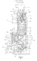
- Fig. 2 the operating state of the filtration operation of this filter element 9 is shown, wherein, as illustrated by flow arrows, the inflowing through the inlet 45 fluid enters the unfiltered portion 37, the backwash guide 21 flows around and via a chamber connection 53, which is located in the wall 41 of the housing main chamber , in the raw side 55 of the element chamber 7 passes.
- the fluid flows through the filter medium 57 from the outside inwards to the clean side 59 of the closed by a chamber lid 61 element chamber 7, from where the purified fluid via a chamber port 63rd to the filtrate side 35 and exits through the filter outlet 43 from the device.
- the Fig. 2 shows that in this operating state of the filtration, the piston 65 is located at the upper end of the cylinder 23 and the fluid chamber 67 adjoining the underside of the piston 65 has its largest volume.
- the chamber 67 as indicated by circular symbols, which are provided with transverse lines, is filled with a quantity of purified fluid, this filling quantity entering the filtration operation via a throttle 69 from the filtrate part 35 out into an inflow line 71, which in Inside the backwash guide 21 is formed and at one end to the adjacent fluid chamber 67 of the piston accumulator 13 is open.
- the other end of this inflow line 71 forms a radially outwardly projecting from the cylinder axis terminal end 73, which in the in Fig. 3 shown filtration operation is closed by contact with the inner wall 41 of the housing main part 1.
- the fluid chamber 79 adjacent to the upper end of the piston 65 has the smallest volume.
- This chamber 79 is for a backwash process, as in Fig. 3 is shown, can be acted upon with compressed air, which can be flowed into the chamber 79 from the gas pressure chamber 15 via a piston accumulator valve.
- a piston accumulator valve In the presentation of Fig. 2 is located within the end piece 47 movable valve piston 81 of the piston accumulator valve in its closed position.
- valve piston 81 in the upwardly moved open position in which its control edge 83 an air inlet 85 from the gas pressure chamber 15 her forth into the fluid chamber 79 releases to drive the accumulator piston 65 down.
- the valve piston 81 by pressure build-up in a valve chamber 87 can be raised by a control line 89 via a control pressure medium is supplied.
- a second control line 91 for the switching of the piston accumulator valve in the closed position there is a second control line 91, which opens at the top of the valve piston 81 in the valve chamber 87.
- the control lines 89 and 91 with a 5/2-way valve 93 ( Fig. 5 ), which in turn is connected to a control pressure source, which is not shown.
- a compressed gas connection 94 compressed air can be fed to the gas pressure chamber 15 from a 3/2-way valve 95.
- a venting port 97 on the directional control valve 95 allows a reduction of the gas pressure in the fluid chamber 79 when the piston accumulator valve is in the open position, so that during filtration operation the lower fluid chamber 67 of the piston accumulator 13 can be filled with cleaned fluid via the throttle 69, wherein the accumulator piston 65 moves upwards emotional.
- the backwash guide 21 is in a rotational position at which the connection ends 73 and 77 of the inflow line 71 and the outflow line 75 coincide with the chamber connections 63 and 53, respectively the element chamber 7 are located.
- the piston accumulator valve is in its open position, so that, as with flow arrows in Fig.
- pressurized gas flows into the fluid chamber 79 of the piston accumulator, the accumulator piston 65 moves down and the fluid located in the fluid chamber 67, cleaned fluid passes as Ruthêtmenge via the inflow line 71 to the clean side 59 of the element chamber 7, wherein a generated by the acting compressed air pressure greedströmung high intensity is generated, which flows through the filter element 9 to be cleaned from the inside out and deters dirt particles from the outside of the filter medium 57 to discharge the contaminants via the discharge line 75 and the Ruthêtauslass 27.
- the backwash line 29 is unlocked in each case via the engine valve 31.
- the backwash line 29 is again blocked, and the compressed air supply is terminated by means of the valve 95, while the valve piston 81 of the piston accumulator valve remains in the open position and the ventilation port 97 is open at the directional control valve 95 , so that the compressed air pressure in the gas pressure chamber 15 and in the fluid chamber 79 is degraded again.
- the fluid chamber 67 is loaded via the throttle 69 again with purified fluid, while the accumulator piston 65 moves upward.
- the piston accumulator valve is closed again by the valve piston 81 is moved down, and the gas pressure chamber 15 is supplied via the directional control valve 95, with closed ventilation port 97 again with compressed air, so that the device for a subsequent backwashing ready is.
Landscapes
- Chemical & Material Sciences (AREA)
- Chemical Kinetics & Catalysis (AREA)
- Filtering Of Dispersed Particles In Gases (AREA)
- Filtration Of Liquid (AREA)
- Fluid-Pressure Circuits (AREA)
Description
- Die Erfindung betrifft eine Filtervorrichtung mit den Merkmalen im Oberbegriff von Anspruch 1.
- Eine in
DE 10 2007 054 737 A1 offenbarte Filtervorrichtung ermöglicht einen kontinuierlichen Filtrationsbetrieb, wobei nacheinander Filterelemente, die zu regenerieren sind, rückgespült werden, während die Filtration über die restlichen Filterelemente fortgesetzt wird, so dass der Filtrationsbetrieb zu keiner Zeit unterbrochen wird. - Bei der bekannten Filtervorrichtung erfolgt der Rückspülvorgang nicht ausschließlich in der Weise, dass der in der Filtervorrichtung anstehende Systemdruck während der jeweiligen Rückspülphase einen Teilstrom des Filtrates das zu reinigende Filterelement in umgekehrter Richtung durchströmen lässt, um den Schmutz vom Element abzulösen und auszutragen, sondern dass, in dem Bestreben, auch hartnäckigere Verschmutzungen entfernen zu können, mittels einer Drucksteuereinrichtung an dem jeweils rückzuspülenden Filterelement ein Unterdruck erzeugt wird. Für die Rückspülung ist daher nicht nur der Systemdruck wirksam, sondern es steht unter Einwirkung der Drucksteuerung ein höherer Druckgradient zum Ablösen von Verschmutzungen zur Verfügung.
- Bei der bekannten Filtervorrichtung weist die Drucksteuereinrichtung ein Absperrelement auf, durch das für einen jeweiligen Rückspülvorgang die Fluidverbindung zwischen dem in das Filtergehäuse einströmenden, zu filtrierenden Fluid und dem betreffenden, rückzuspülenden Filterelement sperrbar ist. Dadurch kommt es bei der vor dem Rückspülvorgang in das Filterelement eintretenden Fluidströmung zu einer Strömungsunterbrechung, so dass die beim Absperrvorgang herrschende Strömungsgeschwindigkeit als strömungsdynamischer Effekt eine Sogwirkung hervorruft. Dadurch steht für das Rückströmen von Filtrat an der Reinseite des betreffenden Filterelementes nicht nur der Systemdruck zur Verfügung, sondern das Rückströmen von Filtrat wird durch die Nachsaugwirkung verstärkt, die aufgrund des dynamischen Effektes zur Verfügung steht, der sich durch das Sperren der Strömung ergibt, die von der Schmutzseite her einströmt.
- Die Größe des durch den Absperrvorgang erzielten hydrodynamischen Effekts ist allerdings von der Strömungsgeschwindigkeit abhängig und daher dementsprechend limitiert. Bei Einsatzgebieten, bei denen mit hartnäckigen Verschmutzungen zu rechnen ist, die von der Filterfläche schwer abzulösen sind, besteht daher die Gefahr, dass die hydrodynamisch unterstützte Rückspülwirkung nicht voll zufriedenstellend ist.
- Eine zur Erfindung gattungsgleiche Filtervorrichtung ist in der
DE 40 30 084 A1 offenbart. Die bekannte Filtervorrichtung weist eine Mehrzahl von Filterelementen, die in einem Filtergehäuse mit einem Filtereinlass für zu filtrierendes Fluid und einem Filterauslass für das gefilterte Fluid aufnehmbar sind, auf, wobei während des Filtrationsvorganges zumindest eines der Filterelemente zum Abreinigen seiner wirksamen Filterfläche mittels einer Rückspüleinrichtung rückspülbar ist, die eine Drucksteuereinrichtung zur Unterstützung der Rückspülung beinhaltet, wobei die Drucksteuereinrichtung einen Hydrospeicher beinhaltet, dessen eine Fluidkammer während des Filtrationsvorganges mit einer Menge an abgereinigtem Fluid befüllbar und für einen Rückspülvorgang über eine Rückspülführung mit der Reinseite des zumindest einen abzureinigenden Filterelements verbindbar ist, und wobei eine weitere Fluidkammer des Hydrospeichers für einen Rückspülvorgang mit einem Mediendruck beaufschlagbar ist, um durch eine dadurch bewirkte Bewegung eines Trennelementes des Hydrospeichers die Füllmenge des abgereinigten Fluids für den Rückspülvorgang zumindest teilweise aus der ersten Fluidkammer wieder abzugeben, wobei die die Menge des abgereinigten Fluids aufnehmende Fluidkammer des Hydrospeichers über eine Drosseleinrichtung befüllbar ist. - Im Hinblick auf diese Problematik stellt sich die Erfindung die Aufgabe, eine Filtervorrichtung zur Verfügung zu stellen, bei der eine durch Drucksteuerung unterstützte, besonders effektive Rückspülwirkung erreichbar ist.
- Erfindungsgemäß ist diese Aufgabe durch eine Filtervorrichtung gelöst, die die Merkmale des Patentanspruches 1 in seiner Gesamtheit aufweist.
- Gemäß dem Kennzeichen von Anspruch 1 ist vorgesehen, dass sich die Drosseleinrichtung zwischen einem Filtratteil eines Hauptraumes des Filtergehäuses und einer Zuströmleitung der Rückspülführung befindet. Dadurch ist sichergestellt, dass der Füllvorgang jeweils stattfindet, ohne dass durch einen größeren, abgezweigten Volumenstrom ein möglicher Abfall des Systemdruckes mit entsprechender Verringerung des Volumenstromes des aus der Vorrichtung abgegebenen Filtrats eintritt.
- Es ist vorgesehen, dass die Drucksteuereinrichtung einen Hydrospeicher beinhaltet, dessen eine Fluidkammer, während die Vorrichtung im Filtrationsbetrieb arbeitet, mit einer Menge an abgereinigtem Fluid befüllbar ist und für einen Rückspülvorgang über eine Rückspülführung mit der Reinseite des jeweils abzureinigenden Filterelements verbindbar ist. Bei einer Druckbeaufschlagung der weiteren Fluidkammer des Hydrospeichers führt die dadurch bewirkte Bewegung des Trennelementes des Hydrospeichers zu einem Ausstoß der Füllmenge des Fluids, das als Spülflüssigkeit über die Rückspülführung zum abzureinigenden Filterelement gelangt.
- Durch Wahl des Mediendruckes, der im Hydrospeicher für die Bewegung des Trennelements zur Anwendung gelangt, hat man es in der Hand, die Strömungsgeschwindigkeit der über die Rückspülführung zum Filterelement gelangenden Spülflüssigkeit optimal an die Gegebenheiten anzupassen, d.h. so zu wählen, dass in Anpassung an die Art des Filtermediums die bestmögliche Spülwirkung erreicht wird. Insbesondere bei verhältnismäßig druckfesten Filterelementen, wie konischen oder zylindrischen Spaltsiebrohrelementen, kann im Hydrospeicher mit hohem Druckniveau und damit hohen Strömungsgeschwindigkeiten gearbeitet werden, wodurch selbst hartnäckige Verschmutzungen von der Filterfläche sicher abgelöst werden.
- Bei vorteilhaften Ausführungsbeispielen ist die weitere Fluidkammer des Hydrospeichers für den Rückspülvorgang mittels einer Ventilsteuereinrichtung mit einer Mediendruckquelle, insbesondere in Form einer Druckgasquelle, verbindbar. In vielen Fällen kann die Verwendung von Pressluft besonders vorteilhaft sein, beispielsweise wenn die Filtervorrichtung in Verbindung mit Anlagen oder Einrichtungen betrieben wird, bei denen eine Pressluftversorgung vorhanden ist. Es versteht sich, dass andere gasförmige Medien, Gas-Alkoholgemische oder Fluid-Feststoff-Gemische als Druckmedien vorgesehen sein könnten. Ebenfalls könnte, insbesondere bei Unterwassereinrichtungen wie Tiefseebohrungen, Seewasser als unter dem Tiefwasserdruck stehendes Druckmedium benutzt werden.
- Bei besonders vorteilhaften Ausführungsbeispielen sind Hydrospeicher und Rückspülführung miteinander verbunden, im Filtergehäuse drehbar angeordnet und für Einstellbewegungen zwischen Filtrationsbetrieb und Rückspülung mittels eines Drehantriebes bewegbar. Eine derartige Anordnung ermöglicht eine besonders einfache und kompakte Bauweise, indem an einem freien und gut zugänglichen Ende des Hydrospeichers ein Antrieb, vorzugsweise in Form eines elektrischen Getriebemotors, angebracht ist, der die Drehbewegung über den Hydrospeicher auf die weiter im Inneren der Vorrichtung gelegene Rückspülführung überträgt und diese in die Drehstellungen einstellt, in denen die Fluidverbindung zum abzureinigenden Filterelement gebildet ist.
- In besonders vorteilhafter Weise kann als Hydrospeicher ein Kolbenspeicher vorgesehen sein, der zusammen mit der an einem Zylinderende angeordneten Rückspülführung um die Zylinderachse drehbar ist. Im Vergleich zu anderen Speicherbauarten, wie Membranspeicher, Federspeicher, Balgspeicher oder dergleichen, zeichnet sich der Kolbenspeicher neben einer besonders robusten Bauweise durch ein gutes Verhältnis zwischen Baugröße und aufnehmbarer Füllmenge an gereinigtem Fluid aus, die dem gesamten Hubraum des Kolbens und somit näherungsweise dem Gesamtvolumen des Speicherzylinders entspricht.
- In besonders vorteilhafter Weise können die Filterelemente in jeweils einer eigenen Elementkammer aufnehmbar sein, die im Filtergehäuse auf einer die Zylinderachse konzentrisch umgebenden Kreislinie angeordnet sind. Bei dieser konzentrischen Anordnung lässt sich die Anschlussverbindung der einzelnen Elementkammern mit der drehbaren Rückspülführung besonders einfach gestalten.
- Mit besonderem Vorteil kann die Anordnung hierbei so getroffen sein, dass die Elementkammern einen ersten, mit der Reinseite des Filterelements verbundenen Kammeranschluss und einen zweiten mit der Rohseite verbundenen Kammeranschluss aufweisen und dass beide dieser Anschlüsse zu einem Hauptraum des Filtergehäuses offen sind, in den hinein sich die drehbare Rückspülführung als Schaltorgan erstreckt, dessen Einstellbewegungen den Zustrom und Abstrom von Fluid zu und vom ersten und zweiten Kammeranschluss für die Rückspülung steuern.
- Für eine besonders kompakte Bauweise kann die Rückspülführung zudem als Trennorgan fungieren, das den Hauptraum des Filtergehäuses in einen den Filterauslass aufweisenden Filtratteil und einen den Filtereinlass aufweisenden Unfiltratteil trennt. Bei größeren Filternennweiten mit langen Filterelementen kann es vorteilhaft sein, den Kolbenspeicher in das Schaltorgan der drehbaren Rückspülführung, zwischen dem ersten mit der Reinseite des Filterelements verbundenen Kammeranschluss und dem zweiten mit der Rohseite verbundenen Kammeranschluss zu integrieren, oder sogar extern anzuordnen und mittels eines Kanals für das Rückspülmedium mit dem Umschaltorgan zu verbinden. Hierfür ist die Anordnung so getroffen, dass die Rückspülführung in einem axialen Abstand vom Kolbenspeicher und von ihrem dazu entgegengesetzten Ende einen einen radialen Vorsprung bildenden Ringkörper mit umfänglicher Radialdichtung aufweist, der zusammen mit der Wand des Hauptraumes diesen in Filtratteil und Unfiltratteil auftrennt.
- Hinsichtlich der Schaltfunktion, die die Rückspülführung bei ihrer Drehbewegung ausführt, kann die Anordnung so getroffen sein, dass sich die Mündung der ersten und zweiten Kammeranschlüsse der Elementkammern an einer eine Zylinderfläche bildenden Wand des Filtratteils bzw. Unfiltratteils des Hauptraumes befinden und dass bei der Einstellung auf Rückspülen von der Zylinderachse jeweils auskragende Anschlussenden von an der Rückspülführung gebildeter Zuströmleitung und Abströmleitung mit den Kammeranschlüssen zur Deckung gelangen, wobei die Zuströmleitung die Verbindung der ersten Fluidkammer des Kolbenspeichers mit dem ersten Kammeranschluss und die Abströmleitung die Verbindung des zweiten Kammeranschlusses mit einem Rückspülausgang des Hauptraumes bilden.
- Vorzugsweise ist der Rückspülausgang mittels einer Ventilanordnung sperrbar und freigebbar.
- Hinsichtlich der die Tätigkeit des Hydrospeichers steuernden Ventileinrichtung kann die Anordnung vorteilhaft so getroffen sein, dass ein durch ein Druckmittel betätigbares Ventil, vorzugsweise in Form eines 5/2-WegeVentils, vorhanden ist, das die Verbindung der mit Druckmedium beaufschlagbaren Fluidkammer des Hydrospeichers mit der betreffenden Druckquelle steuert.
- Bei einem besonders vorteilhaften Ausführungsbeispiel ist ein weiteres Ventil, vorzugsweise in Form eines 3/2-Wege-Ventils, vorgesehen, das in der Verbindung der Fluidkammer mit der Druckquelle angeordnet ist und einen wahlweisen Abbau des Mediumdruckes ermöglicht.
- Nachstehend ist die Erfindung anhand der Zeichnung im Einzelnen erläutert. Es zeigen:
- Fig. 1A bis 1D
- schematisch vereinfacht gezeichnete, perspektivische Schrägansichten der erfindungsgemäßen Filtervorrichtung in einer Ausführungsform mit zwei bzw. drei bzw. vier bzw. fünf Filterelementkammern;
- Fig. 2
- einen gegenüber
Fig. 1 in größerem Maßstab gezeichneten Längsschnitt durch den Zentralbereich einer Elementkammer, wobei der Filtrationsbetrieb verdeutlicht ist; - Fig. 3
- einen der
Fig. 2 entsprechenden Längsschnitt, wobei der Betriebszustand der Rückspülung der geschnitten dargestellten Elementkammer verdeutlicht ist; - Fig. 4
- einen gegenüber
Fig. 2 und3 in größerem Maßstab und abgebrochen gezeichneten Teillängsschnitt lediglich des dem Kolbenspeicherventil benachbarten Teilabschnittes des Ausführungsbeispiels; und - Fig. 5
- einen der
Fig. 4 ähnlichen Teillängsschnitt, jedoch mit demgegenüber verdrehter Lage der Schnittebene. - In der
Fig. 1 , die in den Teilfiguren 1A bis 1D jeweils die Gesamtansicht der erfindungsgemäßen Filtervorrichtung zeigt, sind ein Gehäuse-Hauptteil mit 1, ein Speicherteil mit 3 und ein Antriebsteil mit 5 bezeichnet. DieFig. 1 verdeutlicht auch, dass die erfindungsgemäße Vorrichtung in der Art eines modularen Baukastensystems für einen Betrieb mit einer unterschiedlichen Anzahl von Filterelementen ausbildbar ist. So zeigtFig. 1A ein Beispiel mit zwei Filter-Elementkammern 7, in denen jeweils ein Filterelement 9 (Fig. 2 und3 ) aufnehmbar ist, währendFig. 1B ein Beispiel mit drei Elementkammern 7,Fig. 1C ein Beispiel mit vier Elementkammern 7 undFig. 1D ein Beispiel mit fünf Elementkammern 7 zeigen. Ein Filterelement kann auch aus mehreren Filterkerzen in einem Halter gebildet sein. - Wie den
Fig. 2 und3 entnehmbar ist, ist am oberen offenen Ende 11 des Hauptteils 1 das Speicherteil 3 in Form eines Hohlzylinders angeflanscht, innerhalb dessen koaxial ein Kolbenspeicher 13 angeordnet ist, so dass dessen Zylinderachse die Hochachse des Speicherteils 3 definiert. Ein Zwischenraum zwischen der Außenseite des Kolbenspeichers 13 und dem Mantel des Speicherteils 3 bildet einen Gasdruckraum 15, der am oberen Ende durch einen Gehäusedeckel 17 geschlossen ist und am unteren Ende gegenüber dem Gehäuse-Hauptteil 1 durch den Umfangsrand 19 einer Rückspülführung 21 abgedichtet ist, die mit ihrem Umfangsrand 19 eine dichte Einfassung des unteren Endes des Zylinders 23 des Kolbenspeichers 13 bildet. - Die Rückspülführung 21 erstreckt sich vom unteren offenen Ende des Zylinders 23 weg durch einen Hauptraum des Gehäuse-Hauptteils 1 hindurch bis zu dessen Bodenteil 25, an dem sich ein Rückspülauslass 27 befindet, gegenüber dem die Rückspülführung 21 durch ein Dichtelement 28 abgedichtet ist.
- An den Rückspülauslass 27 schließt sich eine Rückspülleitung 29 an, die mittels eines Motorventils 31 sperrbar und freigebbar ist. Auf etwa halber Länge zwischen Kolbenspeicher 13 und dem am Rückspülauslass 27 befindlichen Ende weist die Rückspülführung 21 einen einen radialen Vorsprung bildenden Ringkörper 33 auf, der den von der Rückspülführung 21 durchgriffenen Hauptraum des Gehäuse-Hauptteils 1 in ein Filtratteil 35 und ein Unfiltratteil 37 trennt. Für die dichte Trennung weist der Ringkörper 33 eine umfängliche Dichtung 39 auf, die mit der Innenwand 41 des Hauptraums zusammenwirkt. Am Filtratteil 35 befindet sich der Filterauslass 43 für das gefilterte Fluid, und am Unfiltratteil 37 befindet sich der Filtereinlass 45 für zu filterndes Fluid.
- Am in der Zeichnung oberen Ende ist der Zylinder 23 des Kolbenspeichers 13 durch ein Endstück 47 geschlossen, dessen oberes Ende mit einem Kupplungsstück 49 verbunden ist, das mit der Ausgangswelle eines Getriebemotors des Antriebsteils 5 verbunden ist. Dadurch ist die gesamte Einheit aus Kolbenspeicher 13 und Rückspülführung 21 gemeinsam innerhalb des Speicherteils 3 und des Gehäuse-Hauptteils 1 drehbar, wobei ein Endschalter 51 zur Kontrolle der Dreheinstellungen vorgesehen ist.
- In den
Fig. 2 und3 ist eine der Filter-Elementkammern 7 in der Schnittdarstellung sichtbar. Jede Elementkammer 7 enthält ein Filterelement 9 in der Art einer Filterkerze zylindrischer oder konischer Form. Beispielsweise kann es sich auch um ein sog. Spaltsiebrohrelement handeln. InFig. 2 ist der Betriebszustand des Filtrationsbetriebs dieses Filterelements 9 dargestellt, wobei, wie mit Strömungpfeilen verdeutlicht, das über den Einlass 45 einströmende Fluid das Unfiltratteil 37 betritt, die Rückspülführung 21 umströmt und über einen Kammeranschluss 53, der sich in der Wand 41 des Gehäuse-Hauptraums befindet, in die Rohseite 55 der Elementkammer 7 gelangt. Von dort durchströmt das Fluid das Filtermedium 57 von außen nach innen zur Reinseite 59 der durch einen Kammerdeckel 61 geschlossenen Elementkammer 7, von wo das gereinigte Fluid über einen Kammeranschluss 63 zur Filtratseite 35 gelangt und über deren Filterauslass 43 aus der Vorrichtung austritt. - Die
Fig. 2 zeigt, dass bei diesem Betriebszustand der Filtration sich der Kolben 65 am oberen Ende des Zylinders 23 befindet und die an die Unterseite des Kolbens 65 angrenzende Fluidkammer 67 ihr größtes Volumen besitzt. Hierbei ist die Kammer 67, wie mit Kreissymbolen, die mit Querstrichen versehen sind, angedeutet ist, mit einer Menge an gereinigtem Fluid befüllt, wobei diese Füllmenge während des Filtrationsbetriebs über eine Drossel 69 aus dem Filtratteil 35 heraus in eine Zuströmleitung 71 eintritt, die im Inneren der Rückspülführung 21 ausgebildet ist und an ihrem einen Ende zur angrenzenden Fluidkammer 67 des Kolbenspeichers 13 hin offen ist. Das andere Ende dieser Zuströmleitung 71 bildet ein von der Zylinderachse radial auskragendes Anschlussende 73, das bei dem inFig. 3 gezeigten Filtrationsbetrieb durch Anlage an der Innenwand 41 des Gehäuse-Hauptteils 1 geschlossen ist. - Am unteren Ende der Rückspülführung 21 bildet diese eine der Bauform der Zuströmleitung 71 entsprechende Abströmleitung 75, die mit dem in der Zeichnung unteren Ende mit der Rückspülleitung 29 verbunden ist und am anderen Ende ebenfalls ein radial auskragendes Anschlussende 77 bildet, das bei der in
Fig. 2 gezeigten Drehposition der Rückspülführung 21 ebenfalls, wie das andere Anschlussende 73, durch Anlage an der Wand 41 geschlossen ist. - Bei dem Betriebszustand von
Fig. 2 hat die am oberen Ende des Kolbens 65 angrenzende Fluidkammer 79 das kleinste Volumen. Diese Kammer 79 ist für einen Rückspülvorgang, wie er inFig. 3 dargestellt ist, mit Druckluft beaufschlagbar, die vom Gasdruckraum 15 her über ein Kolbenspeicherventil in die Kammer 79 einströmbar ist. Bei der Darstellung vonFig. 2 befindet sich der innerhalb des Endstückes 47 bewegbare Ventilkolben 81 des Kolbenspeicherventils in seiner Schließposition. - In
Fig. 4 , die nähere Einzelheiten des Kolbenspeicherventils zeigt, befindet sich dessen Ventilkolben 81 in der nach oben bewegten Öffnungsstellung, bei der seine Steuerkante 83 einen Lufteinlass 85 vom Gasdruckraum 15 her in die Fluidkammer 79 freigibt, um den Speicherkolben 65 nach unten zu treiben. Hierfür ist der Ventilkolben 81 durch Druckaufbau in einer Ventilkammer 87 anhebbar, indem über eine Steuerleitung 89 ein Steuerdruckmedium zugeführt wird. Für die Umschaltung des Kolbenspeicherventils in die Schließposition befindet sich eine zweite Steuerleitung 91, die an der Oberseite des Ventilkolbens 81 in die Ventilkammer 87 mündet. - Für die Betätigung des Kolbenspeicherventils sind die Steuerleitungen 89 und 91 mit einem 5/2-Wege-Ventil 93 (
Fig. 5 ) verbunden, das wiederum mit einer Steuerdruckquelle in Verbindung ist, die nicht dargestellt ist. Über einen Druckgasanschluss 94 ist von einem 3/2-Wege-Ventil 95 her Preßluft zum Gasdruckraum 15 zuführbar. Ein Belüftungsanschluss 97 am Wegeventil 95 ermöglicht bei in Öffnungsstellung befindlichem Kolbenspeicherventil einen Abbau des Gasdrucks in der Fluidkammer 79, so dass während des Filtrationsbetriebes die untere Fluidkammer 67 des Kolbenspeichers 13 mit abgereinigtem Fluid über die Drossel 69 befüllbar ist, wobei sich der Speicherkolben 65 nach oben bewegt. - Die
Fig. 3 zeigt den Betriebszustand der Rückspülung der in der Darstellung geschnitten dargestellten Elementkammer 7. Wie gezeigt, befindet sich die Rückspülführung 21 in einer Drehposition, bei der sich die Anschlussenden 73 und 77 von Zuströmleitung 71 bzw. Abströmleitung 75 in Deckung mit den Kammeranschlüssen 63 bzw. 53 der Elementkammer 7 befinden. Das Kolbenspeicherventil befindet sich in seiner Öffnungsstellung, so dass, wie mit Strömungspfeilen inFig. 3 angedeutet, Druckgas in die Fluidkammer 79 des Kolbenspeichers einströmt, den Speicherkolben 65 nach unten bewegt und das in der Fluidkammer 67 befindliche, abgereinigte Fluid als Rückspülmenge über die Zuströmleitung 71 zur Reinseite 59 der Elementkammer 7 gelangt, wobei eine durch den wirkenden Pressluftdruck erzeugte Rückspülströmung hoher Intensität erzeugt wird, die das abzureinigende Filterelement 9 von innen nach außen durchströmt und Schmutzpartikel von der Außenseite des Filtermediums 57 ablöst, um die Verschmutzungen über die Abströmleitung 75 und den Rückspülauslass 27 auszutragen. Für einen solchen Rückspülvorgang ist die Rückspülleitung 29 jeweils über das Motorventil 31 entsperrt. Nachdem der Rückspülvorgang bei Erreichen der unteren Endlage des Speicherkolbens 65 abgeschlossen ist, wird die Rückspülleitung 29 wieder gesperrt, und die Pressluftzufuhr wird mittels des Ventils 95 beendet, während der Ventilkolben 81 des Kolbenspeicherventils in der Offenstellung verbleibt und der Belüftungsanschluss 97 am Wegeventil 95 offen ist, so dass der Pressluftdruck in dem Gasdruckraum 15 und in der Fluidkammer 79 wieder abgebaut wird. Bei dem sich anschließenden Filtrationsbetrieb wird so die Fluidkammer 67 über die Drossel 69 wieder mit gereinigtem Fluid beladen, während sich der Speicherkolben 65 nach oben bewegt. Wenn dies der Fall ist, wird das Kolbenspeicherventil wieder geschlossen, indem der Ventilkolben 81 nach unten bewegt wird, und der Gasdruckraum 15 wird über das Wegeventil 95, bei geschlossenem Belüftungsanschluss 97, wieder mit Pressluft versorgt, so dass die Vorrichtung für einen nachfolgenden Rückspülvorgang bereit ist.
Claims (11)
- Filtervorrichtung mit einer Mehrzahl von Filterelementen (9), die in einem Filtergehäuse (1) mit einem Filtereinlass (45) für zu filtrierendes Fluid und einem Filterauslass (43) für das gefilterte Fluid aufnehmbar sind, wobei während des Filtrationsvorganges zumindest eines der Filterelemente (9) zum Abreinigen seiner wirksamen Filterfläche mittels einer Rückspüleinrichtung (13, 21) rückspülbar ist, die eine Drucksteuereinrichtung (13) zur Unterstützung der Rückspülung beinhaltet, wobei die Drucksteuereinrichtung einen Hydrospeicher (13) beinhaltet, dessen eine Fluidkammer (67) während des Filtrationsvorganges mit einer Menge an abgereinigtem Fluid befüllbar und für einen Rückspülvorgang über eine Rückspülführung (21) mit der Reinseite (59) des zumindest einen abzureinigenden Filterelementes (9) verbindbar ist, und wobei eine weitere Fluidkammer (79) des Hydrospeichers (13) für einen Rückspülvorgang mit einem Mediendruck beaufschlagbar ist, um durch eine dadurch bewirkte Bewegung eines Trennelementes (65) des Hydrospeichers (13) die Füllmenge des abgereinigten Fluids für den Rückspülvorgang zumindest teilweise aus der ersten Fluidkammer (67) wieder abzugeben, wobei die die Menge des abgereinigten Fluids aufnehmende Fluidkammer (67) des Hydrospeichers (13) über eine Drosseleinrichtung (69) befüllbar ist, dadurch gekennzeichnet, dass sich die Drosseleinrichtung (69) zwischen einem Filtratteil (35) eines Hauptraumes des Filtergehäuses (1) und einer Zuströmleitung (71) der Rückspülführung (21) befindet.
- Filtervorrichtung nach Anspruch 1, dadurch gekennzeichnet, dass die weitere Fluidkammer (79) des Hydrospeichers (13) für den Rückspülvorgang mittels einer Ventilsteuereinrichtung (81, 93, 95) mit einer Mediendruckquelle, insbesondere in Form einer Druckgasquelle, verbindbar ist.
- Filtervorrichtung nach Anspruch 1 oder 2, dadurch gekennzeichnet, dass Hydrospeicher (13) und Rückspülführung (21) miteinander verbunden, im Filtergehäuse (1, 3) drehbar angeordnet und für Einstellbewegungen zwischen Filtrationsbetrieb und Rückspülung mittels eines Drehantriebes (5) bewegbar sind.
- Filtervorrichtung nach einem der vorstehenden Ansprüche, dadurch gekennzeichnet, dass als Hydrospeicher ein Kolbenspeicher (13) vorgesehen ist, der zusammen mit der an einem Zylinderende (11) angeordneten Rückspülführung (21) um die Zylinderachse drehbar ist.
- Filtervorrichtung nach einem der vorstehenden Ansprüche, dadurch gekennzeichnet, dass die Filterelemente (9) in jeweils einer eigenen Elementkammer (7) aufnehmbar sind, die im Filtergehäuse (1) auf einer die Zylinderachse konzentrisch umgebenden Kreislinie angeordnet sind.
- Filtervorrichtung nach Anspruch 5, dadurch gekennzeichnet, dass die Elementkammern (7) einen ersten, mit der Reinseite (59) des Filterelements (9) verbundenen Kammeranschluss (63) und einen zweiten, mit der Rohseite (55) verbundenen Kammeranschluss (53) aufweisen und dass beide dieser Anschlüsse zu einem Hauptraum des Filtergehäuses (1) offen sind, in den hinein sich die drehbare Rückspülführung (21) als Schaltorgan erstreckt, dessen Einstellbewegungen den Zustrom und Abstrom von Fluid zu und vom ersten (63) und zweiten Kammeranschluss (53) für die Rückspülung steuern.
- Filtervorrichtung nach einem der vorstehenden Ansprüche, dadurch gekennzeichnet, dass die Rückspülführung (21) in einem axialen Abstand vom Kolbenspeicher (13) und von ihrem dazu entgegengesetzten Ende einen einen radialen Vorsprung bildenden Ringkörper (33) mit umfänglicher Radialdichtung (39) aufweist, der zusammen mit einer Wand (41) des Hauptraumes diesen in einen den Filterauslass (43) aufweisenden Filtratteil (35) und einen den Filtereinlass (45) aufweisenden Unfiltratteil (37) trennt.
- Filtervorrichtung nach Anspruch 6, dadurch gekennzeichnet, dass sich die Mündung der ersten und zweiten Kammeranschlüsse (63 bzw. 53) an einer eine Zylinderfläche bildenden Wand (41) des Filtratteils (35) bzw. Unfiltratteils (37) des Hauptraumes befinden und dass bei der Einstellung auf Rückspülen von der Zylinderachse jeweils auskragende Anschlussenden (73, 77) von an der Rückspülführung (21) gebildeter Zuströmleitung (71) und Abströmleitung (75) mit den Kammeranschlüssen (63, 53) zur Deckung gelangen, wobei die Zuströmleitung (71) die Verbindung der ersten Fluidkammer (67) des Kolbenspeichers (13) mit dem ersten Kammeranschluss (63) und die Abströmleitung (75) die Verbindung des zweiten Kammeranschlusses (53) mit einem Rückspülausgang (27) des Hauptraumes bilden.
- Filtervorrichtung nach Anspruch 8, dadurch gekennzeichnet, dass der Rückspülausgang (27) mittels einer Ventilanordnung (31) sperrbar und freigebbar ist.
- Filtervorrichtung nach einem der Ansprüche 2 bis 9, dadurch gekennzeichnet, dass eine Ventilsteuerung ein durch ein Druckmittel betätigbares Ventil, vorzugsweise in Form eines 5/2-Wege-Ventils (93), aufweist, das die Verbindung der mit Druckmedium beaufschlagbaren Fluidkammer (79) des Hydrospeichers (13) mit der betreffenden Druckquelle steuert.
- Filtervorrichtung nach einem der Ansprüche 2 bis 10, dadurch gekennzeichnet, dass ein weiteres Ventil, vorzugsweise in Form eines 3/2-Wege-Ventils (95), über das die Fluidkammer (79) des Hydrospeichers (13) mit der Druckquelle verbindbar ist, einen wahlweisen Abbau des Mediendruckes im Hydrospeicher (13) ermöglicht.
Applications Claiming Priority (2)
| Application Number | Priority Date | Filing Date | Title |
|---|---|---|---|
| DE102011100518A DE102011100518A1 (de) | 2011-05-05 | 2011-05-05 | Filtervorrichtung |
| PCT/EP2012/001772 WO2012150010A1 (de) | 2011-05-05 | 2012-04-26 | Filtervorrichtung |
Publications (2)
| Publication Number | Publication Date |
|---|---|
| EP2704812A1 EP2704812A1 (de) | 2014-03-12 |
| EP2704812B1 true EP2704812B1 (de) | 2019-02-20 |
Family
ID=46027902
Family Applications (2)
| Application Number | Title | Priority Date | Filing Date |
|---|---|---|---|
| EP12724887.0A Active EP2704812B1 (de) | 2011-05-05 | 2012-04-26 | Filtervorrichtung |
| EP12718912.4A Active EP2704811B1 (de) | 2011-05-05 | 2012-04-26 | Filtervorrichtung |
Family Applications After (1)
| Application Number | Title | Priority Date | Filing Date |
|---|---|---|---|
| EP12718912.4A Active EP2704811B1 (de) | 2011-05-05 | 2012-04-26 | Filtervorrichtung |
Country Status (9)
| Country | Link |
|---|---|
| US (2) | US11058975B2 (de) |
| EP (2) | EP2704812B1 (de) |
| JP (2) | JP6158790B2 (de) |
| KR (2) | KR101961088B1 (de) |
| CN (2) | CN103517744B (de) |
| DE (1) | DE102011100518A1 (de) |
| DK (2) | DK2704811T3 (de) |
| PL (1) | PL2704811T3 (de) |
| WO (2) | WO2012150010A1 (de) |
Families Citing this family (10)
| Publication number | Priority date | Publication date | Assignee | Title |
|---|---|---|---|---|
| CN103100254B (zh) * | 2013-02-05 | 2015-05-20 | 品孚罗特过滤设备(北京)有限公司 | 一种不间断过滤的过滤装置 |
| DE102015002767A1 (de) * | 2015-03-05 | 2016-09-08 | Hydac Process Technology Gmbh | Filtervorrichtung |
| DE102015015237A1 (de) * | 2015-11-25 | 2017-06-01 | Hydac Process Technology Gmbh | Filtervorrichtung |
| DE102017002646A1 (de) * | 2017-03-18 | 2018-09-20 | Hydac Process Technology Gmbh | Filtervorrichtung |
| IL251485A0 (en) * | 2017-03-30 | 2017-05-29 | אוליאל ערן | water filter |
| US10307698B2 (en) * | 2017-05-03 | 2019-06-04 | Jacob H. Berg | Multiple cartridge fluid filter canister |
| DE102017004661A1 (de) * | 2017-05-08 | 2018-11-08 | Hydac Process Technology Gmbh | Filtervorrichtung |
| DE102017009990A1 (de) * | 2017-10-26 | 2019-05-02 | Hydac Process Technology Gmbh | Filtervorrichtung |
| DE102023003883A1 (de) | 2023-09-25 | 2025-03-27 | Hydac Process Technology Gmbh | System |
| GB2644073A (en) * | 2024-09-13 | 2026-03-18 | Inheriting Earth Ltd | System for separating particulates from a fluid and method |
Family Cites Families (18)
| Publication number | Priority date | Publication date | Assignee | Title |
|---|---|---|---|---|
| US2731107A (en) * | 1954-05-07 | 1956-01-17 | Jr Henry J Hersey | Filter |
| FR83147E (fr) * | 1961-05-12 | 1964-06-19 | Procédé et dispositifs de décolmatage de filtres disposés dans des circuits de fluides fonctionnant sous pression ou sous vide | |
| DE1241803B (de) * | 1963-03-04 | 1967-06-08 | Muller Jacques | Absperrvorrichtung zum automatischen, periodischen Entschlammen von Filterkerzen durch Rueckspuelung |
| FR1437838A (fr) * | 1965-06-11 | 1966-05-06 | Filtre comportant un dispositif de nettoyage automatique pour tous fluides | |
| US4055500A (en) * | 1976-02-10 | 1977-10-25 | Parker Leland L | Filtering apparatus and quick-opening backwash valve therefor |
| JPS63119820A (ja) * | 1986-11-10 | 1988-05-24 | Koyago Takasuke | 全自動濾過装置 |
| DE3832679A1 (de) * | 1988-09-27 | 1990-03-29 | Boll & Kirch Filter | Rueckspuelfilter |
| DE4030084C2 (de) * | 1990-09-22 | 1999-09-30 | Boll & Kirch Filter | Rückspülfilter |
| DE4345412C2 (de) * | 1993-11-26 | 1999-11-11 | Boll & Kirch Filter | Filterkerze |
| DE19636254C2 (de) * | 1996-09-06 | 1999-01-14 | Premark Feg L L C N D Ges D St | Vorrichtung und Verfahren zum Filtern von Suspensionen |
| US5906751A (en) * | 1997-10-10 | 1999-05-25 | Parker; Leland L. | Filtering apparatus with improved quick-opening backwash valve |
| FI107127B (fi) * | 1999-11-11 | 2001-06-15 | Parker Hannifin Oy | Menetelmä ja laitteisto nesteen suodattamiseksi |
| DE19956859A1 (de) * | 1999-11-25 | 2001-06-07 | Hydac Filtertechnik Gmbh | Rückspülfiltervorrichtung |
| US6461525B2 (en) * | 2000-08-01 | 2002-10-08 | Tetra Process Technologies | Method for backwashing granular media filters and bioreactors |
| DE10325525B4 (de) * | 2003-06-04 | 2013-10-24 | Boll & Kirch Filterbau Gmbh | Rückspülfilter |
| DE102007019222B3 (de) * | 2007-04-24 | 2008-10-23 | Bela Seebach | Filteranlage mit Rückspüleinrichtung |
| DE102007054737A1 (de) | 2007-11-16 | 2009-05-20 | Hydac Process Technology Gmbh | Filtervorrichtung |
| US20100101269A1 (en) * | 2008-10-24 | 2010-04-29 | Theodore Jr Michael | Compressor with improved oil separation |
-
2011
- 2011-05-05 DE DE102011100518A patent/DE102011100518A1/de not_active Withdrawn
-
2012
- 2012-04-26 EP EP12724887.0A patent/EP2704812B1/de active Active
- 2012-04-26 US US13/261,770 patent/US11058975B2/en active Active
- 2012-04-26 KR KR1020137032066A patent/KR101961088B1/ko active Active
- 2012-04-26 WO PCT/EP2012/001772 patent/WO2012150010A1/de not_active Ceased
- 2012-04-26 KR KR1020137032075A patent/KR101950167B1/ko active Active
- 2012-04-26 US US13/261,764 patent/US9855520B2/en active Active
- 2012-04-26 DK DK12718912.4T patent/DK2704811T3/en active
- 2012-04-26 CN CN201280021885.2A patent/CN103517744B/zh active Active
- 2012-04-26 JP JP2014508705A patent/JP6158790B2/ja active Active
- 2012-04-26 CN CN201280021848.1A patent/CN103561837B/zh active Active
- 2012-04-26 DK DK12724887.0T patent/DK2704812T3/da active
- 2012-04-26 JP JP2014508706A patent/JP6006295B2/ja active Active
- 2012-04-26 EP EP12718912.4A patent/EP2704811B1/de active Active
- 2012-04-26 PL PL12718912T patent/PL2704811T3/pl unknown
- 2012-04-26 WO PCT/EP2012/001773 patent/WO2012150011A1/de not_active Ceased
Non-Patent Citations (1)
| Title |
|---|
| None * |
Also Published As
| Publication number | Publication date |
|---|---|
| US9855520B2 (en) | 2018-01-02 |
| CN103561837A (zh) | 2014-02-05 |
| JP2014512953A (ja) | 2014-05-29 |
| DE102011100518A1 (de) | 2012-11-08 |
| US20140091021A1 (en) | 2014-04-03 |
| WO2012150011A8 (de) | 2013-01-24 |
| DK2704811T3 (en) | 2017-12-18 |
| KR20140038977A (ko) | 2014-03-31 |
| JP2014516772A (ja) | 2014-07-17 |
| EP2704811A1 (de) | 2014-03-12 |
| JP6006295B2 (ja) | 2016-10-12 |
| CN103561837B (zh) | 2016-08-17 |
| CN103517744B (zh) | 2016-08-24 |
| KR20140038976A (ko) | 2014-03-31 |
| PL2704811T3 (pl) | 2018-04-30 |
| CN103517744A (zh) | 2014-01-15 |
| KR101961088B1 (ko) | 2019-03-25 |
| US11058975B2 (en) | 2021-07-13 |
| KR101950167B1 (ko) | 2019-02-20 |
| WO2012150010A1 (de) | 2012-11-08 |
| EP2704811B1 (de) | 2017-11-08 |
| EP2704812A1 (de) | 2014-03-12 |
| JP6158790B2 (ja) | 2017-07-05 |
| US20140202938A1 (en) | 2014-07-24 |
| WO2012150011A1 (de) | 2012-11-08 |
| DK2704812T3 (da) | 2019-05-13 |
Similar Documents
| Publication | Publication Date | Title |
|---|---|---|
| EP2704812A1 (de) | Filtervorrichtung | |
| DE10151864B4 (de) | Verfahren zum Betrieb eines Filters für Flüssigkeiten und System zur Durchführung des Verfahrens | |
| EP1237640B1 (de) | Rückspülfiltervorrichtung | |
| DE102011111457B4 (de) | Filtervorrichtung | |
| EP2207609B1 (de) | Filtervorrichtung | |
| DE112014006168B4 (de) | Filterelement und Filtervorrichtung | |
| EP2448647B1 (de) | Filtervorrichtung | |
| DE1761106C3 (de) | Filter zur Reinigung von mit Feststoffen vermischten Flüssigkeiten | |
| EP3265202B1 (de) | System zum filtrieren von fluiden | |
| EP0875286B1 (de) | Filtervorrichtung mit Membranmodul | |
| DE1241802B (de) | Filterapparat | |
| DE10340366B4 (de) | Filtervorrichtung | |
| DE102007003925A1 (de) | Filteranlage | |
| DE19542578A1 (de) | Rückspülbare Filtervorrichtung mit Druckgas | |
| DE1786118A1 (de) | Selbstreinigende Filtervorrichtung | |
| EP3380212B1 (de) | Filtervorrichtung | |
| EP2364761B1 (de) | Rückspülbare Filteranordnung | |
| DE77145C (de) | Trommelfilter | |
| EP3838371B1 (de) | Fluidfilter und verfahren zur abreinigung eines fluidfilters | |
| DE20220668U1 (de) | System zur Regeneration eines Filtermittels eines Filters | |
| EP4115964B1 (de) | Filtervorrichtung | |
| DE7435463U (de) | Druckfilter für Trüben | |
| DE69615380T2 (de) | Selbstreinigender filter zum filtrieren von flüssigkeiten und gasen | |
| DE3245093A1 (de) | Rueckspuelfilter | |
| DE20014299U1 (de) | Rückspülfilter für flüssige Medien |
Legal Events
| Date | Code | Title | Description |
|---|---|---|---|
| PUAI | Public reference made under article 153(3) epc to a published international application that has entered the european phase |
Free format text: ORIGINAL CODE: 0009012 |
|
| 17P | Request for examination filed |
Effective date: 20131004 |
|
| AK | Designated contracting states |
Kind code of ref document: A1 Designated state(s): AL AT BE BG CH CY CZ DE DK EE ES FI FR GB GR HR HU IE IS IT LI LT LU LV MC MK MT NL NO PL PT RO RS SE SI SK SM TR |
|
| DAX | Request for extension of the european patent (deleted) | ||
| 17Q | First examination report despatched |
Effective date: 20160630 |
|
| STAA | Information on the status of an ep patent application or granted ep patent |
Free format text: STATUS: EXAMINATION IS IN PROGRESS |
|
| GRAP | Despatch of communication of intention to grant a patent |
Free format text: ORIGINAL CODE: EPIDOSNIGR1 |
|
| STAA | Information on the status of an ep patent application or granted ep patent |
Free format text: STATUS: GRANT OF PATENT IS INTENDED |
|
| INTG | Intention to grant announced |
Effective date: 20180928 |
|
| GRAS | Grant fee paid |
Free format text: ORIGINAL CODE: EPIDOSNIGR3 |
|
| GRAA | (expected) grant |
Free format text: ORIGINAL CODE: 0009210 |
|
| STAA | Information on the status of an ep patent application or granted ep patent |
Free format text: STATUS: THE PATENT HAS BEEN GRANTED |
|
| AK | Designated contracting states |
Kind code of ref document: B1 Designated state(s): AL AT BE BG CH CY CZ DE DK EE ES FI FR GB GR HR HU IE IS IT LI LT LU LV MC MK MT NL NO PL PT RO RS SE SI SK SM TR |
|
| REG | Reference to a national code |
Ref country code: GB Ref legal event code: FG4D Free format text: NOT ENGLISH |
|
| REG | Reference to a national code |
Ref country code: CH Ref legal event code: EP |
|
| REG | Reference to a national code |
Ref country code: DE Ref legal event code: R096 Ref document number: 502012014290 Country of ref document: DE |
|
| REG | Reference to a national code |
Ref country code: AT Ref legal event code: REF Ref document number: 1097426 Country of ref document: AT Kind code of ref document: T Effective date: 20190315 |
|
| REG | Reference to a national code |
Ref country code: IE Ref legal event code: FG4D Free format text: LANGUAGE OF EP DOCUMENT: GERMAN |
|
| REG | Reference to a national code |
Ref country code: DK Ref legal event code: T3 Effective date: 20190506 |
|
| REG | Reference to a national code |
Ref country code: SE Ref legal event code: TRGR |
|
| REG | Reference to a national code |
Ref country code: NL Ref legal event code: MP Effective date: 20190220 |
|
| REG | Reference to a national code |
Ref country code: LT Ref legal event code: MG4D |
|
| PG25 | Lapsed in a contracting state [announced via postgrant information from national office to epo] |
Ref country code: NO Free format text: LAPSE BECAUSE OF FAILURE TO SUBMIT A TRANSLATION OF THE DESCRIPTION OR TO PAY THE FEE WITHIN THE PRESCRIBED TIME-LIMIT Effective date: 20190520 Ref country code: PT Free format text: LAPSE BECAUSE OF FAILURE TO SUBMIT A TRANSLATION OF THE DESCRIPTION OR TO PAY THE FEE WITHIN THE PRESCRIBED TIME-LIMIT Effective date: 20190620 Ref country code: LT Free format text: LAPSE BECAUSE OF FAILURE TO SUBMIT A TRANSLATION OF THE DESCRIPTION OR TO PAY THE FEE WITHIN THE PRESCRIBED TIME-LIMIT Effective date: 20190220 Ref country code: NL Free format text: LAPSE BECAUSE OF FAILURE TO SUBMIT A TRANSLATION OF THE DESCRIPTION OR TO PAY THE FEE WITHIN THE PRESCRIBED TIME-LIMIT Effective date: 20190220 |
|
| PG25 | Lapsed in a contracting state [announced via postgrant information from national office to epo] |
Ref country code: IS Free format text: LAPSE BECAUSE OF FAILURE TO SUBMIT A TRANSLATION OF THE DESCRIPTION OR TO PAY THE FEE WITHIN THE PRESCRIBED TIME-LIMIT Effective date: 20190620 Ref country code: BG Free format text: LAPSE BECAUSE OF FAILURE TO SUBMIT A TRANSLATION OF THE DESCRIPTION OR TO PAY THE FEE WITHIN THE PRESCRIBED TIME-LIMIT Effective date: 20190520 Ref country code: GR Free format text: LAPSE BECAUSE OF FAILURE TO SUBMIT A TRANSLATION OF THE DESCRIPTION OR TO PAY THE FEE WITHIN THE PRESCRIBED TIME-LIMIT Effective date: 20190521 Ref country code: LV Free format text: LAPSE BECAUSE OF FAILURE TO SUBMIT A TRANSLATION OF THE DESCRIPTION OR TO PAY THE FEE WITHIN THE PRESCRIBED TIME-LIMIT Effective date: 20190220 Ref country code: RS Free format text: LAPSE BECAUSE OF FAILURE TO SUBMIT A TRANSLATION OF THE DESCRIPTION OR TO PAY THE FEE WITHIN THE PRESCRIBED TIME-LIMIT Effective date: 20190220 Ref country code: HR Free format text: LAPSE BECAUSE OF FAILURE TO SUBMIT A TRANSLATION OF THE DESCRIPTION OR TO PAY THE FEE WITHIN THE PRESCRIBED TIME-LIMIT Effective date: 20190220 |
|
| PG25 | Lapsed in a contracting state [announced via postgrant information from national office to epo] |
Ref country code: CZ Free format text: LAPSE BECAUSE OF FAILURE TO SUBMIT A TRANSLATION OF THE DESCRIPTION OR TO PAY THE FEE WITHIN THE PRESCRIBED TIME-LIMIT Effective date: 20190220 Ref country code: RO Free format text: LAPSE BECAUSE OF FAILURE TO SUBMIT A TRANSLATION OF THE DESCRIPTION OR TO PAY THE FEE WITHIN THE PRESCRIBED TIME-LIMIT Effective date: 20190220 Ref country code: SK Free format text: LAPSE BECAUSE OF FAILURE TO SUBMIT A TRANSLATION OF THE DESCRIPTION OR TO PAY THE FEE WITHIN THE PRESCRIBED TIME-LIMIT Effective date: 20190220 Ref country code: AL Free format text: LAPSE BECAUSE OF FAILURE TO SUBMIT A TRANSLATION OF THE DESCRIPTION OR TO PAY THE FEE WITHIN THE PRESCRIBED TIME-LIMIT Effective date: 20190220 Ref country code: EE Free format text: LAPSE BECAUSE OF FAILURE TO SUBMIT A TRANSLATION OF THE DESCRIPTION OR TO PAY THE FEE WITHIN THE PRESCRIBED TIME-LIMIT Effective date: 20190220 Ref country code: ES Free format text: LAPSE BECAUSE OF FAILURE TO SUBMIT A TRANSLATION OF THE DESCRIPTION OR TO PAY THE FEE WITHIN THE PRESCRIBED TIME-LIMIT Effective date: 20190220 |
|
| REG | Reference to a national code |
Ref country code: DE Ref legal event code: R097 Ref document number: 502012014290 Country of ref document: DE |
|
| PG25 | Lapsed in a contracting state [announced via postgrant information from national office to epo] |
Ref country code: PL Free format text: LAPSE BECAUSE OF FAILURE TO SUBMIT A TRANSLATION OF THE DESCRIPTION OR TO PAY THE FEE WITHIN THE PRESCRIBED TIME-LIMIT Effective date: 20190220 Ref country code: SM Free format text: LAPSE BECAUSE OF FAILURE TO SUBMIT A TRANSLATION OF THE DESCRIPTION OR TO PAY THE FEE WITHIN THE PRESCRIBED TIME-LIMIT Effective date: 20190220 |
|
| REG | Reference to a national code |
Ref country code: CH Ref legal event code: PL |
|
| REG | Reference to a national code |
Ref country code: BE Ref legal event code: MM Effective date: 20190430 |
|
| PLBE | No opposition filed within time limit |
Free format text: ORIGINAL CODE: 0009261 |
|
| STAA | Information on the status of an ep patent application or granted ep patent |
Free format text: STATUS: NO OPPOSITION FILED WITHIN TIME LIMIT |
|
| PG25 | Lapsed in a contracting state [announced via postgrant information from national office to epo] |
Ref country code: MC Free format text: LAPSE BECAUSE OF FAILURE TO SUBMIT A TRANSLATION OF THE DESCRIPTION OR TO PAY THE FEE WITHIN THE PRESCRIBED TIME-LIMIT Effective date: 20190220 Ref country code: LU Free format text: LAPSE BECAUSE OF NON-PAYMENT OF DUE FEES Effective date: 20190426 |
|
| 26N | No opposition filed |
Effective date: 20191121 |
|
| PG25 | Lapsed in a contracting state [announced via postgrant information from national office to epo] |
Ref country code: LI Free format text: LAPSE BECAUSE OF NON-PAYMENT OF DUE FEES Effective date: 20190430 Ref country code: CH Free format text: LAPSE BECAUSE OF NON-PAYMENT OF DUE FEES Effective date: 20190430 |
|
| PG25 | Lapsed in a contracting state [announced via postgrant information from national office to epo] |
Ref country code: SI Free format text: LAPSE BECAUSE OF FAILURE TO SUBMIT A TRANSLATION OF THE DESCRIPTION OR TO PAY THE FEE WITHIN THE PRESCRIBED TIME-LIMIT Effective date: 20190220 Ref country code: BE Free format text: LAPSE BECAUSE OF NON-PAYMENT OF DUE FEES Effective date: 20190430 |
|
| PG25 | Lapsed in a contracting state [announced via postgrant information from national office to epo] |
Ref country code: TR Free format text: LAPSE BECAUSE OF FAILURE TO SUBMIT A TRANSLATION OF THE DESCRIPTION OR TO PAY THE FEE WITHIN THE PRESCRIBED TIME-LIMIT Effective date: 20190220 |
|
| PG25 | Lapsed in a contracting state [announced via postgrant information from national office to epo] |
Ref country code: IE Free format text: LAPSE BECAUSE OF NON-PAYMENT OF DUE FEES Effective date: 20190426 |
|
| REG | Reference to a national code |
Ref country code: AT Ref legal event code: MM01 Ref document number: 1097426 Country of ref document: AT Kind code of ref document: T Effective date: 20190426 |
|
| PG25 | Lapsed in a contracting state [announced via postgrant information from national office to epo] |
Ref country code: AT Free format text: LAPSE BECAUSE OF NON-PAYMENT OF DUE FEES Effective date: 20190426 |
|
| PG25 | Lapsed in a contracting state [announced via postgrant information from national office to epo] |
Ref country code: CY Free format text: LAPSE BECAUSE OF FAILURE TO SUBMIT A TRANSLATION OF THE DESCRIPTION OR TO PAY THE FEE WITHIN THE PRESCRIBED TIME-LIMIT Effective date: 20190220 |
|
| PG25 | Lapsed in a contracting state [announced via postgrant information from national office to epo] |
Ref country code: MT Free format text: LAPSE BECAUSE OF FAILURE TO SUBMIT A TRANSLATION OF THE DESCRIPTION OR TO PAY THE FEE WITHIN THE PRESCRIBED TIME-LIMIT Effective date: 20190220 Ref country code: HU Free format text: LAPSE BECAUSE OF FAILURE TO SUBMIT A TRANSLATION OF THE DESCRIPTION OR TO PAY THE FEE WITHIN THE PRESCRIBED TIME-LIMIT; INVALID AB INITIO Effective date: 20120426 |
|
| PG25 | Lapsed in a contracting state [announced via postgrant information from national office to epo] |
Ref country code: MK Free format text: LAPSE BECAUSE OF FAILURE TO SUBMIT A TRANSLATION OF THE DESCRIPTION OR TO PAY THE FEE WITHIN THE PRESCRIBED TIME-LIMIT Effective date: 20190220 |
|
| PGFP | Annual fee paid to national office [announced via postgrant information from national office to epo] |
Ref country code: FR Payment date: 20250317 Year of fee payment: 14 |
|
| PGFP | Annual fee paid to national office [announced via postgrant information from national office to epo] |
Ref country code: DE Payment date: 20250430 Year of fee payment: 14 |
|
| PGFP | Annual fee paid to national office [announced via postgrant information from national office to epo] |
Ref country code: IT Payment date: 20250407 Year of fee payment: 14 |
|
| PGFP | Annual fee paid to national office [announced via postgrant information from national office to epo] |
Ref country code: SE Payment date: 20260205 Year of fee payment: 15 |
|
| PGFP | Annual fee paid to national office [announced via postgrant information from national office to epo] |
Ref country code: GB Payment date: 20260210 Year of fee payment: 15 |
|
| PGFP | Annual fee paid to national office [announced via postgrant information from national office to epo] |
Ref country code: DK Payment date: 20260209 Year of fee payment: 15 |
|
| PGFP | Annual fee paid to national office [announced via postgrant information from national office to epo] |
Ref country code: FI Payment date: 20260206 Year of fee payment: 15 |