EP2703595B1 - Tilting roller blind with guides for roof windows - Google Patents
Tilting roller blind with guides for roof windows Download PDFInfo
- Publication number
- EP2703595B1 EP2703595B1 EP13004211.2A EP13004211A EP2703595B1 EP 2703595 B1 EP2703595 B1 EP 2703595B1 EP 13004211 A EP13004211 A EP 13004211A EP 2703595 B1 EP2703595 B1 EP 2703595B1
- Authority
- EP
- European Patent Office
- Prior art keywords
- casing
- guides
- flexible screen
- window
- cavity
- Prior art date
- Legal status (The legal status is an assumption and is not a legal conclusion. Google has not performed a legal analysis and makes no representation as to the accuracy of the status listed.)
- Revoked
Links
Images


Classifications
-
- E—FIXED CONSTRUCTIONS
- E04—BUILDING
- E04D—ROOF COVERINGS; SKY-LIGHTS; GUTTERS; ROOF-WORKING TOOLS
- E04D13/00—Special arrangements or devices in connection with roof coverings; Protection against birds; Roof drainage; Sky-lights
- E04D13/03—Sky-lights; Domes; Ventilating sky-lights
- E04D13/035—Sky-lights; Domes; Ventilating sky-lights characterised by having movable parts
- E04D13/0351—Sky-lights; Domes; Ventilating sky-lights characterised by having movable parts the parts pivoting about a fixed axis
- E04D13/0354—Sky-lights; Domes; Ventilating sky-lights characterised by having movable parts the parts pivoting about a fixed axis the parts being flat
-
- E—FIXED CONSTRUCTIONS
- E04—BUILDING
- E04D—ROOF COVERINGS; SKY-LIGHTS; GUTTERS; ROOF-WORKING TOOLS
- E04D13/00—Special arrangements or devices in connection with roof coverings; Protection against birds; Roof drainage; Sky-lights
- E04D13/03—Sky-lights; Domes; Ventilating sky-lights
- E04D13/033—Sky-lights; Domes; Ventilating sky-lights provided with means for controlling the light-transmission or the heat-reflection, (e.g. shields, reflectors, cleaning devices)
-
- E—FIXED CONSTRUCTIONS
- E06—DOORS, WINDOWS, SHUTTERS, OR ROLLER BLINDS IN GENERAL; LADDERS
- E06B—FIXED OR MOVABLE CLOSURES FOR OPENINGS IN BUILDINGS, VEHICLES, FENCES OR LIKE ENCLOSURES IN GENERAL, e.g. DOORS, WINDOWS, BLINDS, GATES
- E06B9/00—Screening or protective devices for wall or similar openings, with or without operating or securing mechanisms; Closures of similar construction
- E06B9/24—Screens or other constructions affording protection against light, especially against sunshine; Similar screens for privacy or appearance; Slat blinds
- E06B9/40—Roller blinds
- E06B9/42—Parts or details of roller blinds, e.g. suspension devices, blind boxes
-
- E—FIXED CONSTRUCTIONS
- E06—DOORS, WINDOWS, SHUTTERS, OR ROLLER BLINDS IN GENERAL; LADDERS
- E06B—FIXED OR MOVABLE CLOSURES FOR OPENINGS IN BUILDINGS, VEHICLES, FENCES OR LIKE ENCLOSURES IN GENERAL, e.g. DOORS, WINDOWS, BLINDS, GATES
- E06B9/00—Screening or protective devices for wall or similar openings, with or without operating or securing mechanisms; Closures of similar construction
- E06B9/56—Operating, guiding or securing devices or arrangements for roll-type closures; Spring drums; Tape drums; Counterweighting arrangements therefor
- E06B9/58—Guiding devices
- E06B9/581—Means to prevent or induce disengagement of shutter from side rails
-
- E—FIXED CONSTRUCTIONS
- E06—DOORS, WINDOWS, SHUTTERS, OR ROLLER BLINDS IN GENERAL; LADDERS
- E06B—FIXED OR MOVABLE CLOSURES FOR OPENINGS IN BUILDINGS, VEHICLES, FENCES OR LIKE ENCLOSURES IN GENERAL, e.g. DOORS, WINDOWS, BLINDS, GATES
- E06B9/00—Screening or protective devices for wall or similar openings, with or without operating or securing mechanisms; Closures of similar construction
- E06B9/56—Operating, guiding or securing devices or arrangements for roll-type closures; Spring drums; Tape drums; Counterweighting arrangements therefor
- E06B9/92—Means allowing the closures to be shifted out of the plane of the opening
-
- E—FIXED CONSTRUCTIONS
- E04—BUILDING
- E04F—FINISHING WORK ON BUILDINGS, e.g. STAIRS, FLOORS
- E04F10/00—Sunshades, e.g. Florentine blinds or jalousies; Outside screens; Awnings or baldachins
- E04F10/02—Sunshades, e.g. Florentine blinds or jalousies; Outside screens; Awnings or baldachins of flexible canopy materials, e.g. canvas ; Baldachins
- E04F10/06—Sunshades, e.g. Florentine blinds or jalousies; Outside screens; Awnings or baldachins of flexible canopy materials, e.g. canvas ; Baldachins comprising a roller-blind with means for holding the end away from a building
- E04F10/0607—Sunshades, e.g. Florentine blinds or jalousies; Outside screens; Awnings or baldachins of flexible canopy materials, e.g. canvas ; Baldachins comprising a roller-blind with means for holding the end away from a building with guiding-sections for supporting the movable end of the blind
-
- E—FIXED CONSTRUCTIONS
- E04—BUILDING
- E04F—FINISHING WORK ON BUILDINGS, e.g. STAIRS, FLOORS
- E04F10/00—Sunshades, e.g. Florentine blinds or jalousies; Outside screens; Awnings or baldachins
- E04F10/02—Sunshades, e.g. Florentine blinds or jalousies; Outside screens; Awnings or baldachins of flexible canopy materials, e.g. canvas ; Baldachins
- E04F10/06—Sunshades, e.g. Florentine blinds or jalousies; Outside screens; Awnings or baldachins of flexible canopy materials, e.g. canvas ; Baldachins comprising a roller-blind with means for holding the end away from a building
- E04F10/0644—Sunshades, e.g. Florentine blinds or jalousies; Outside screens; Awnings or baldachins of flexible canopy materials, e.g. canvas ; Baldachins comprising a roller-blind with means for holding the end away from a building with mechanisms for unrolling or balancing the blind
- E04F10/0655—Sunshades, e.g. Florentine blinds or jalousies; Outside screens; Awnings or baldachins of flexible canopy materials, e.g. canvas ; Baldachins comprising a roller-blind with means for holding the end away from a building with mechanisms for unrolling or balancing the blind acting on the movable end, e.g. front bar
-
- E—FIXED CONSTRUCTIONS
- E06—DOORS, WINDOWS, SHUTTERS, OR ROLLER BLINDS IN GENERAL; LADDERS
- E06B—FIXED OR MOVABLE CLOSURES FOR OPENINGS IN BUILDINGS, VEHICLES, FENCES OR LIKE ENCLOSURES IN GENERAL, e.g. DOORS, WINDOWS, BLINDS, GATES
- E06B9/00—Screening or protective devices for wall or similar openings, with or without operating or securing mechanisms; Closures of similar construction
- E06B9/56—Operating, guiding or securing devices or arrangements for roll-type closures; Spring drums; Tape drums; Counterweighting arrangements therefor
- E06B9/68—Operating devices or mechanisms, e.g. with electric drive
- E06B9/72—Operating devices or mechanisms, e.g. with electric drive comprising an electric motor positioned inside the roller
Description
- The present invention relates to roof window assembly comprising a window having a frame and a sash, the assembly further comprising a tilting roller blind with guides set, basically designed for a said roof window, particularly the window that opens by rotating its sash around a horizontal axis located in the central zone of the window slightly above the half of window sash height. The tilting roller blind with guides according to the present invention may also be applied in windows installed vertically in walls.
- Current state of the art. Solution, know from French application
FR2595403 A1 - From the Polish patent description No.
205319 - The drawbacks of the above-mentioned prior art shall be avoided by the present invention, i.e. by means of a roof window assembly according to the
present claim 1. For this purpose the roof window assembly comprises a roof window having a frame and a sash and further said assembly comprising tilting roller blind with guides set. Basically tilting roller blind is designed for said roof window and, particularly, for installation outside the window that opens by rotating its sash around a horizontal axis located slightly above the half of window sash height, the said roller blind comprising the flexible screen terminated with a sliding beam and having two screen guides for guiding this flexible screen located at the window sides, the said screen guides having the form of sections with open cavities directed towards each other and used for guiding the ends of the sliding beam, and also having edge cavities which guide the edges of flexible screen, in particular the screen made of fabric. Edge cavities of both screen guides feature slidable guiding inserts along these cavities and preferably made of plastic. Each guiding insert has two angular ribs arranged symmetrically in such a way that the longitudinal gap is formed between their arms which are bent and directed towards each other. Along the edges of the flexible screen, the catches are equidistantly fixed having the gripping elements with the width greater than the width of the slot in slidable guiding insert. These gripping elements are directed towards the outer side of the flexible screen and move inside the slidable guiding insert. When the sliding beam moves away of the casing, the beam ends are driven by cords wound on reels installed inside the casing and rewound through return pulleys installed at the guide ends opposite with respect to the casing. Moreover, the roller blind according to the invention is also equipped with the casing which is fastened in the tilting manner, particularly in articulated manner, to the top member of the window frame. In this casing the flexible screen is stored when it is coiled on the shaft, which is, in particular, driven by an electric motor installed inside the shaft. Also, the roller blind has the tilting guides connected with these window sash corners which are opposite the cassette; in such arrangement the set of guides is tilted during window opening and closing, preferably together with the casing, so as these guides keep up with the moving corners of the window sash. - In each screen guide, i.e. the left and right one, the edge cavity which guides the edge of the flexible screen is separated from the screen movement zone by two ribs located opposite each other. The width of longitudinal gap between the ends of these ribs is slightly greater than the distance between outer surfaces of angular ribs of the slidable guiding insert located inside the edge cavity. Preferably, the edge cavity in the screen guide form the deeper part of the cavity for guiding of the sliding beam and is separated from this cavity by two ribs located opposite each other.
- The wall of slidable guiding insert, opposite with respect to the longitudinal gap in this insert, has outer arms that reach beyond the angular ribs of the insert at its both sides. These arms constitute the extensions of the central arm which extends between angular ribs and plays a role of the bottom of the cavity in guiding insert. Between the outer portions of this wall and the ribs which separate the edge cavity from the flexible screen movement zone the elastic inserts are provided, preferably made of cellular rubber; these elastic inserts push the slidable guiding inserts in both screen guides away towards outside and therefore stretch the flexible screen in the direction perpendicular to the screen unwinding direction.
- The catch assemblies which operate together with the slidable guiding inserts are made in the form of sliding tapes fastened to the flexible screen along both edges. The gripping elements of each sliding tapes, which are located on the outer edge of the tape and move inside the slidable guiding inserts, are preferably made of plastic and have the form of oblong, continuous, spatial loop structure. This structure is composed of small loops arranged transversely with respect to the tape surface; the outer width of the loops is greater than the width of the gap in slidable guiding insert and the transverse loops are connected with each other by small longitudinal loops in such a way that each transverse loop connects through the longitudinal loop with the transverse loop adjacent to it from the casing side and through the another longitudinal loop with the transverse loop adjacent to it on the opposite side. The longitudinal loops are arranged alternately on both opposite surfaces of the tape, parallel to it, and are joined with the tape, particularly by welding. The sliding tape is made separately from the basic part of the flexible screen, and the edge of the tape which is opposite with respect to the edge equipped with catches is lap connected with the edge of the basic part of flexible screen.
- In the casing designed for storage of flexible screen of the tilting roller blind the rewinding shaft is provided, located at this side of the casing where the flexible screen leaves the casing and enters into edge cavities in the guides. The rewinding shaft is bearing mounted in the bodies located at both casing ends which play a role of bearing components which connect the casing with the guides. Preferably, the rewinding shaft is mounted in sliding sleeves inserted into bodies from the outer side, and each body has the channel through which the neck of the shaft is inserted and which has the seat for sliding sleeve at its end. The diameter of the seat and the outer diameter of the sleeve are both greater than the channel width. Therefore, when the neck of rewinding shaft is inserted in the seat through the channel and sliding sleeve is slid over the neck, the shape-type connection is obtained which prevents movements of rewinding shaft and only allows the shaft to rotate in the sleeves.
- The tilting guides are made in the form of sections with cavities in which the elements that connect the tilting guides with lower corners of the window sash move. Preferably, the cavities in both tilting guides are open and these openings face each other. The tilting guide can be made as the monolithic section with the flexible screen guide and its sliding beam, or can be made in the form of separate section, particularly extending parallel to the flexible screen guide and its sliding beam and joined with this guide. The tilting guide connects with the window sash through the pin which is preferably fastened to the cover plate fixed to the window sash frame and rotatably connected with the slide which moves inside the tilting guide cavity. Alternatively, the pin may be fastened directly to the window sash frame. The connection between the pin and the slide is made by placing the part of the pin protruding from the window sash in the slide seat, where the pin is snap-locked and secured against unintended disconnection of the pin and the slide.
- In another solution of connection between the tilting guide and the window sash, the roller is mounted on the pin fixed to the window sash corner; the diameter of the roller is greater than the width of the tilting guide cavity access slot. During assembly the roller is inserted into this cavity from the face of tilting guide.
- The section from which the guide for flexible screen and the sliding beam is made, also has the angular cavity arranged at the side opposite to the cavity employed for guiding the ends of the sliding beam. In this angular cavity the part of the cord moves which extends between the reel inside the casing and the cord return assembly. Upon passing through the return pulley, this cord goes to the sliding beam to which its end is fastened. The entrance gap to the angular cavity is located between the tilting guide and the side cover of the screen guide and opens towards the window frame. Preferably in the cord return assembly two pulleys are provided rather than a single bigger pulley, because in such solution the ends of transverse beam can move closer to the return pulley and, therefore, shorter screen guides may be used.
- The ends of cords that pull the sliding beam to cause its movement out of the casing are fixed to this beam, and the cords remain under the action of the tensioning assembly which takes up any cord slack resulting from different and varying winding diameters of the flexible screen on the shaft and cords on reels. The tensioning assembly is, in particular, arranged in the form of springs located in the sliding beam, one spring for each cord.
- Beneficial effects of the invention. Use of the slidable guiding inserts for catches which are located along the edges of flexible screen and stretch this screen in the direction transverse with respect to the screen guides and the window, so usually along the shorter distance than stretching the screen longitudinally, reduces the value of screen deflection between guides and eliminates or at least reduces the risk of the screen contacting with the window glass, particularly when the window is closed. This ensures the natural convection of air between the flexible screen and the window glass and, in consequence, cooling of the window. Because the screen winding shaft and the axis of casing rotation during its tilting together with the window sash are coaxial, and also because the rewinding shaft is located at the same side where the flexible screen leaves the casing, the compact structure of the entire assembly is obtained along with unobstructed tilting movement of the roller blind with guides.
- Exemplary embodiments of the invention. The tilting roller blind with guides according to the invention is presented on an example of the roller blind installed on the roof window and illustrated on the following figures, of which:
- Fig. 1
- depicts a roof window with a tilting roller blind with guides set joined with the window sash - in axonometric projection;
- Fig. 2
- depicts how the casing is fixed to the window frame (detail "A" on
Fig. 1 ) - in axonometric projection; - Fig. 3
- depicts the left-side guide of the roller blind with the edge guide for flexible screen and tilting guide with the slide - in the section made transversely with respect to these guides;
- Fig. 4
- depicts the slidable guiding insert and the sliding tape (detail "B" on
Fig. 3 ) - in cross-sectional view; - Fig. 5
- depicts the edge of flexible screen, with sliding tape and a set of its catching elements - in axonometric projection;
- Fig. 6
- depicts the left side of the casing and the guide connected with the casing - in exploded axonometric view with partial cross-section shown;
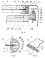
- Fig. 7
- depicts the casing with flexible screen and sliding beam in uppermost position - in the cross section made by vertical plane;
- Fig. 8
- depicts the longitudinal section through the left-side guide, at its end opposite to the casing, and through the sliding beam operating together with the guide.
- Example 1. The tilting roller with guides, installed on the outer side of roof window, having the
casing 1 for winding and storage offlexible screen 2, further having twoguides 3 connected perpendicularly to thecasing 1 and located respectively on left and right side of thewindow 4. The assembly ofguides 3 andcasing 1 may tilt, since thecasing 1 is joined with the upper part of theframe 41 of thewindow 4 in articulating manner and the ends ofguides 3 opposite the casing are connected with lower corners of thesash 42 of thewindow 4 which opens by rotation of thesash 42 around thehinges 43 located slightly above the half of the length of side members ofwindow frame 41. During window opening theguides 3 andcasing 1 tilt, keeping pace with the rotating movement of lower part of thewindow sash 42. The purpose ofguides 3 is to keep theflexible screen 2 stretched across thewindow 4, i.e. in horizontal direction, regardless the position of the screen remaining stationary with respect to thecasing 1, and also guiding the screen edges along thewindow 4 during winding or unwinding of the screen. - The
casing 1 of the roller blind assembly is fixed to theframe 41 of thewindow 4 by mountingrail 11 having the form of box-shaped section and located on the upper member ofwindow frame 41 and fastened to this frame by threaded fasteners. Thecasing 1 is connected with mountingrail 11 in articulated way by two (left and right)holders 12 located at respective ends of the casing. Eachholder 12 consists of thebase plate 12a andbearing plate 12b perpendicular to the base plate and having the bearing opening in which thecasing 1 is seated in a pivoting manner. Theholder 12 is fastened to the mountingrail 11 by inserting itsbase plate 12a under theangular rib 11a and engaging it with the flat rib of mountingrail 11. Theholder 12 is protected against inadvertent detachment from the mounting rail by thescrew 12c which is mounted in the holder and whose head is pressed down to the retainingrib 11c of the mounting rail. This mounting solution allows for quick and easy mounting of thecasing 1 withholders 12 on the mountingrail 11 previously fastened to thewindow frame 41. - The
casing 1 is equipped with twobodies 13, the left and the right one, located near its ends and playing a role of bearing assemblies which join the casing withguides 3. In eachbody 13 thecylindrical protrusion 13a is provided which is directed towards outside of thecasing 1 and pivotably seated in thebearing plate 12b of theholder 12 by inserting it into the bearing opening equipped with four slidinginserts 12d made of polyamide plastic and arranged circumferentially in the bearing opening. The purpose of slidinginserts 12d is to reduce the resistance to motion of thecylindrical protrusion 13a inside the bearing opening and, in consequence, the resistance to rotational motion of thecasing 1 with respect toholders 12. - The
flexible screen 2 is made of fabric, particularly the fabric made of plastic guiding cavitiesfibres featuring with reduced light transmittance, and is resistant to rain and other weather factors. The screen is wound in thecasing 1 on theshaft 5 arranged coaxially with bearing openings in bearingplates 12b of theholders 12 which fasten thecasing 1 to the mountingrail 11. The edge offlexible screen 2 unwound from theshaft 5 in the casing and parallel to this shaft is fixed in thetransverse beam 21 having theends 22 engaged inguides 3 perpendicular to thecasing 1 and connected withbodies 13 of this casing. The ends 22 oftransverse beam 21 move inguides 3 during winding or unwinding of theflexible screen 2 or remain stationary with respect to the guides when the screen stays in position set by the user. - The
guides 3 are arranged in the form of extruded metal sections with guidingcavities 31 facing each other and designed for taking in theends 22 of slidingbeam 21. In each guide the deeper part of guidingcavity 31 is arranged in the form ofedge cavity 32 separated from guiding cavity by tworibs 33 located opposite to each other and separated with a gap. Along the entire length ofedge cavity 32 in theguide 3 theslidable guiding insert 6 is provided made of polyamide material and having twoangular ribs 61 located symmetrically in such arrangement that a longitudinal slot is formed between their bent arms facing each other. Through this slot the slidingtape 7, which is lap connected with the edge offlexible screen 2, goes into the slidable guiding insert. More precisely, through this slot theflat tape 71 passes which constitutes a bearing part of sliding tape. The catching elements of slidingtape 7 located inside thecavity 62 of theslidable guiding insert 6 are made in the form of continuous, oblong spatial loop structure made of plastic material. This structure is composed ofsmall loops 72 perpendicular to the surface oftape 71 and mutually connected by longitudinal loops. Each transverse loop connects through the outerlongitudinal loop 73 with thetransverse loop 72 adjacent to it from the casing side, and through the innerlongitudinal loop 74 with thetransverse loop 72 adjacent to it on the side opposite with respect to the casing, i.e. on the side where thereturn assembly 34 is located at the end of theguide 3. The outerlongitudinal loops 72 and the innerlongitudinal loops 73 are alternately arranged on both opposite surfaces of thetape 71, being parallel and adherent to them, and are joined with thetape 71 by welding. The longitudinal loops are referred to as the inner (73) or the outer (72) ones based on their location with respect to thetape 71, i.e. from the window side or the outer side, respectively. - In the
slidable guiding insert 6 the wall located opposite the longitudinal slot and playing a role of the bottom of cavity in this guiding insert containouter arms 63 which on both sides reach beyond theangular ribs 61 of the insert. Between theouter arms 63 of this wall and theribs 61 which separate theedge cavity 32 from guidingcavity 31 theelastic inserts 64 are located, which are made of cellular rubber material and push the slidable guiding inserts 6 in bothguides 3 towards outside. - Because the outer width of
transverse loops 72 of slidingtape 7 is greater than the width of the slot betweenangular ribs 61 of theslidable guiding insert 6, the oblong, continuous spatial loop structure may move in thecavity 62 of the guidinginsert 6 only, and during unwinding of theflexible screen 2 the successivetransversal loops 72 of the slidingtape 7 enter thecavity 62 from the face ofslidable guiding insert 6 on thecasing 1. The slidable guiding inserts 6, being pushed towards outside byelastic inserts 64, pull the slidingtapes 7 and stretch theflexible screen 2 in the direction perpendicular to the unwinding direction, i.e. horizontally across thewindow 4. - In the
casing 1 of the roller blind, directly next to theshaft 5 which is employed for winding and unwinding offlexible screen 2 the rewindingshaft 51 is provided which directs theflexible screen 2 into theguides 3 and the slidingtapes 7 attached to the screen edges into the slidable guiding inserts 6 in these guides. Locating the rewindingshaft 51 at the side where theflexible screen 2 leaves thecasing 1 allows for shaping the cylindrical surface of theopposite side 14 of the casing (seeFig. 7 ) in such a way that thecasing 1 together withguides 3 may tilt, and the entire assembly still features with compact structure and small outline dimensions. - The rewinding
shaft 1 is bearing mounted in bothbodies 13 of the casing by itsend necks 52 which engage in both bodies from the inner side, i.e. from the side directed to the opposite body. Thenecks 52 are located in slidingsleeves 53, which in turn are inserted intobodies 13 from the outer side. Also, on the inner side of eachbody 13 thechannel 13b is provided for the purpose of entering theneck 52 of the rewinding shaft to its seating position, and eachchannel 13b terminates with theseat 13c for the slidingsleeve 53. The outer diameter ofsleeve 53 is greater than the width of thechannel 13b, therefore upon inserting theneck 52 into theseat 13c through thechannel 13b and inserting the slidingsleeve 53 into theseat 13c with simultaneous sliding it over theneck 52 of rewinding shaft the shape-forced connection is obtained which allows rotational movements of rewindingshaft 51 in slidingsleeves 53 and simultaneously prevents the shaft from displacing. The slidingsleeve 53 is fixed in thebody 13 by thecover 15 fastened to the body by screws and equipped with protrudingpart 15a which presses the flange of sliding sleeve against the retaining surface of the body. The sliding surface also has thespur 53a which is located in longitudinal groove cut in the seat for this sleeve provided in the body. This spur blocks the rotational movement of the sleeve with respect to the body, so as only theneck 52 slides in thesleeve 53. - The
shaft 5 on which theflexible screen 2 is wound in thecasing 1 is driven byelectric motor 54 hidden inside this shaft. The face ofmotor 54 is fastened to thecover 15 by screws that pass through theholes 15b in the cover, and is also aligned with the cover by centring pin protruding from it and entering theseat 54a provided in theelectric motor 54. - The movement of
flexible screen 2 during unwinding, as well as stretching this screen along the window length is caused by thecords 8 which pass inguides 3; said cords move thetransverse beam 21 away of thecasing 1. One end of the cord is fastened to and wound onto thereel 81 which is located in thecasing 1 and rotates together with theshaft 5 when the latter winds theflexible screen 2 in such fashion that thecords 8 andflexible screen 2 winds in opposite directions, i.e. during unwinding of the screen the cord winds on the reel and, reversely, the cord unwinds from the reel during winding the screen on the shaft. Thereels 81 on both sides of casing are driven by central part of theshaft 5 through splined connectingmembers 55 which have the central part of reduced diameter, thus leaving a space for slidingtape 7 wound on the shaft, particularly for the loop structure of the tape which is thicker than theflexible screen 2. The other end ofcord 8 is, upon passing over two return pulleys 82 mounted in thereturn assembly 34 located on the end ofguide 3, secured in the slidingbeam 21. At the distance between thereel 81 in thecasing 1 and returnpulleys 82 in thereturn assembly 34 thecord 8 runs through theangular cavity 35 in theguide 3 which has the access slot open towards thewindow frame 41. Between the return pulleys 82 in thereturn assembly 34 and theend 22 of the slidingbeam 21 thecord 8 runs through the guidingcavity 31 in theguide 3. Inside the slidingbeam 21 thecord 8 remains under the action ofspringloaded tensioning device 83 which takes up any slack ofcord 8 resulting from different and varying winding diameters of theflexible screen 2 on theshaft 5 and thecords 8 onreels 81. - Apart from the cavities intended for guiding the flexible screen and its cord, each
guide 3 is also equipped with tiltingguide 36 located in parallel to the main section of theguide 3 of the roller blind assembly. The tiltingguide 36 is arranged in the form of channel section with ends of its arms bent towards each other and defining the cavity for theslide 37 which connects theguide 3 with lower corner of thesash 42 of theroof window 4. The tilting guides 36 are so located in bothguides 3 that their cavities for engaging theslides 37 are open towards each other. The tiltingguide 36 connects with the main section of theguide 3 through the longitudinal, T-shaped spline 35a which is inserted to the T-slot in the main section from the face ofguide 3. Thesash 42 of thewindow 4 is connected with tiltingguide 36 through thepin 44 fastened to thecover plate 45 affixed to thewindow sash frame 42. In this exemplary embodiment of the invention thepin 44 is made in the form of the cylindrical head screw threaded into thecover plate 45. The head of this screw is inserted into the seat in theslide 37 and secured there against inadvertent disconnection of thepin 44 and theslide 37 by snap-locking connection. - Example 2. The tilting roller blind with guides, installed on the outer side of roof window differs from the first exemplary embodiment of the invention in that that instead the slide the roller moves inside the tilting guide, and the diameter of this roller is greater than the width of access slot provided in the tilting guide cavity and open towards the opposite guide. The rollers which operate together with both guides are pivotably mounted on pins installed in the same way as in the first exemplary embodiment, in cover plates affixed to the corners of window sash. During assembly of guides the roller is inserted to the cavity in tilting guide from the face of this guide, prior to connecting the guide to the casing. Other components and parts of tilting roller blind, as well as the casing design, including the location of rewinding shaft are the same as in the first exemplary embodiment of the invention.
- Example 3 which does not belong to the present invention. The tilting roller blind with guides is installed on vertical window mounted in the building wall. As in the first exemplary embodiment of the invention, the casing is fixed to the top member of the window frame. At lower ends of both guides the short tilting guides are provided which operate together with articulated connecting members pivotably mounted to the lower part of window frame and terminated with rollers placed in tilting guides. Other components and parts of tilting roller blind, including the solution for guiding of flexible screen edges and the design of casing with location of rewinding shaft are identical as in the first exemplary embodiment of the invention.
Claims (10)
- Roof window assembly comprising a roof window (4) having a frame (41) and a sash, (42) the assembly further comprising a tilting roller blind with a set of guides (3, 36), especially designed for roof windows, particularly installed outside the window (4) that opens by rotating its sash (42) around a horizontal axis located above the half of the window sash height, the tilting roller blind comprising a flexible screen (2) which is wound onto a shaft (5) designed for winding the flexible screen (2) on it and driven by a motor (54), preferably an electric motor, the flexible screen (2) being terminated with a sliding beam (21) with the ends guided by screen guides (3), the assembly further comprising a casing (1) fixed in a tilting manner, especially affixed to the top member of the window frame (41), wherein said casing (1) is designed for holding the flexible screen (2), the screen guides (3) are made of shapes with guiding cavities (31) open towards each other for guiding the ends of the sliding beam (21) and with edge cavities (32) designed for guiding the edges of the said flexible screen (2), and wherein said roller blind further comprises tilting guides (36) connected to the window sash corners located opposite the casing (1), therefore during window opening and closing the set of guides (3, 36) may tilt, preferably together with the casing (1), furthermore, slidable guiding inserts (6), preferably made of plastic, are provided in the edge cavities (32), and each of these slidable guiding inserts (6) has two angular ribs (61) arranged symmetrically in such manner that between their arms directed to each other a longitudinal slot is formed, and to the edges of flexible screen (2) catches are affixed in regular intervals, said catches have the gripping elements (72) with the width greater than the width of said slot, these gripping elements (72) move inside the slidable guiding insert (6); the narrower portions of the catches pass through the slot between angular ribs of this insert, and the ends (22) of the sliding beam (21) are pulled away from the casing (1) by cords (8) wound on reels (81) located in the casing and rewound by return pulleys (82) located on the ends of the screen guides (3) located opposite the casing (1).
- Roof window assembly according to claim 1, characterized in that the edge cavity (32) is separated from the flexible screen (2) movement zone by the ribs (33) located opposite each other, the longitudinal slot is provided between these ribs and the width of this slot is slightly greater than the distance between outer surfaces of angular ribs (61) of the slidable guiding insert (6).
- Roof window assembly according to claim 1 or 2, characterized in that the edge cavity (62) designed for guiding the edge of flexible screen (2) is made as the deeper part of guiding cavity (31) for sliding beam (21) and is separated from this cavity by two ribs (33) located opposite each other.
- Roof window assembly according to any of claims 1 to 3, characterized in that the sets of catches operating together with slidable guiding insert have the form of sliding tapes (7) fixed to the flexible screen (2) along its both edges, and the gripping elements of each sliding tape, located on the outer edge of the tape and placed inside the slidable guiding insert, have the form of oblong, continuous spatial structure, preferably made of plastic and composed of small loops (72) arranged transversely with respect to the surface of the tape (71) and connected with each other by small longitudinal loops in such a way that each transverse loop is connected through the one longitudinal loop (73) with the transverse loop adjacent to it from the casing side and through the another longitudinal loop (74) with the transverse loop adjacent to it on the opposite side, and the longitudinal loops are arranged alternately at both opposite surfaces of the tape (71) parallel to it, and are joined with the tape (71).
- Roof window assemblyaccording to any of claims 2 to 4, characterized in that the wall of slidable guiding insert (6) located opposite to the slot has the outer arms (63) which reach beyond the angular ribs (61) of this insert, and between the outer parts of this wall and the ribs (33) which separate the edge cavity (32) from the flexible screen movement zone the elastic inserts (64) are provided, preferably made of cellular rubber, which stretch the flexible screen (2) in the direction perpendicular to the screen unwinding direction.
- Roof window assemblyaccording to any of claims 1 to 5, characterized in that inside the casing (1) the rewinding shaft (51) is provided which is located at this side of casing at which the flexible screen (2) leaves the casing (1) towards edge cavities (32) provided in guides (3), and the shaft (51) is bearing mounted in bodies (13) located at both ends of the casing (1) and connecting this casing with guides (3).
- Roof window assembly according to claim 6, characterized in that the rewinding shaft (51) is mounted in sliding sleeves (53) inserted in bodies (13) from outer side, and that in each of these bodies the channel (13b) is provided for engaging the neck (51) of rewinding shaft (51), this channel terminates with the seat (13c) for sliding sleeve (53) and the sleeve diameter is greater than the channel width.
- Roof window assembly according to any of claims 1 to 7, characterized in that the tilting guides (36) have the cavities in which the elements that connects these guides with lower corners of the window move, and that as the connecting element the pin (44) is used, preferably fastened to the cover plate (45) which is affixed to the widow sash frame (52), the pin (44) is in pivoting manner connected with the slide (37) that move inside the cavity in the tilting guide (36), and the pin (44) is located in the seat provided in the slide (37) and blocked in it by snap-locking connection.
- Roof window assembly according to any of claims 1 to 8, characterized in that the section from which the guide (3) is made has the angular cavity (35) arranged on the side opposite with respect to the guiding cavity (31), and inside this angular cavity the part of cord (8) moves which extends between the reel (81) located inside the casing (1) and the return assembly (34), this return assembly preferably contains two return pulleys (82), and the access slot of the angular cavity (35) opens towards the window frame.
- Roof window assembly according to claim 9, characterized in that the cords (8) which cause the sliding beam to move away of the casing (1) remain under the action of the tensioning assembly (83,) particularly made in the form of springs located in the sliding beam.
Applications Claiming Priority (1)
| Application Number | Priority Date | Filing Date | Title |
|---|---|---|---|
| PL400631A PL221436B1 (en) | 2012-09-03 | 2012-09-03 | Tilting roller blind with guides, especially for the roof window |
Publications (3)
| Publication Number | Publication Date |
|---|---|
| EP2703595A2 EP2703595A2 (en) | 2014-03-05 |
| EP2703595A3 EP2703595A3 (en) | 2015-05-27 |
| EP2703595B1 true EP2703595B1 (en) | 2016-02-24 |
Family
ID=49084720
Family Applications (1)
| Application Number | Title | Priority Date | Filing Date |
|---|---|---|---|
| EP13004211.2A Revoked EP2703595B1 (en) | 2012-09-03 | 2013-08-27 | Tilting roller blind with guides for roof windows |
Country Status (2)
| Country | Link |
|---|---|
| EP (1) | EP2703595B1 (en) |
| PL (1) | PL221436B1 (en) |
Families Citing this family (4)
| Publication number | Priority date | Publication date | Assignee | Title |
|---|---|---|---|---|
| EP3015637B1 (en) * | 2014-10-29 | 2019-04-17 | VKR Holding A/S | Screening device for a roof window and method for mounting such a screening device on a roof window |
| DE102015116287A1 (en) * | 2015-09-25 | 2017-03-30 | Reiner Detenhoff | Swivel bearing of a guide for an exhibitable roller shutter and pivotally mounted roller shutter guide |
| PL240870B1 (en) * | 2017-08-07 | 2022-06-20 | Fakro Pp Spolka Z Ograniczona Odpowiedzialnoscia | Driving unit of a roller blind, preferably the strip jalousie |
| EP3959410A1 (en) * | 2019-11-25 | 2022-03-02 | VKR Holding A/S | A screening arrangement with a shielding device |
Citations (14)
| Publication number | Priority date | Publication date | Assignee | Title |
|---|---|---|---|---|
| JP2001107666A (en) | 1999-10-05 | 2001-04-17 | Hayashiguchi Kogyo Kk | Roll screen and screen therefor |
| DE102006020573A1 (en) | 2006-05-01 | 2007-11-15 | Mallmann, Hans-Jürgen | Stretching device for e.g. marquee of right-angled tarpaulin, has plastic lateral channel held in another lateral channel such that chamber is not vacated and moved in extracting direction |
| BE1017146A3 (en) | 2005-05-24 | 2008-03-04 | Vero Duco Nv | SCREEN DEVICE WITH A SCREEN FITTED ON THE WIDE SIDE. |
| DE202009003723U1 (en) | 2009-03-09 | 2009-05-28 | J. Paul Gmbh | Protective device for a door or window arrangement of a building |
| BE1017767A5 (en) | 2007-09-26 | 2009-06-02 | Renson Ventilation Nv | SCREEN DEVICE. |
| WO2009098433A1 (en) | 2008-02-07 | 2009-08-13 | Licciardi Di Stefano, Carmelo, Joseph | Screen system with a bracket for mounting a guiding rail |
| EP2157275A2 (en) | 2008-07-24 | 2010-02-24 | Kestelyn NV | Screen device |
| EP1669537B1 (en) | 2004-12-10 | 2010-03-24 | Corradi S.P.A. | Guiding assembly for roll-up awnings |
| EP2236731A2 (en) | 2009-03-13 | 2010-10-06 | Hunter Douglas Industries B.V. | Covering arrangement for architectural openings |
| CH702041B1 (en) | 2008-03-07 | 2011-04-29 | Storama Ag Fuer Sonnen Und Wetterschutz Technik | Guiding rail for e.g. sun curtain, has guiding slot exhibiting between two open ends of C-profile, and fibers extending in longitudinal direction, where rail is made of duro-plastic, in which filaments are laid in traction direction |
| CN201883916U (en) | 2010-12-03 | 2011-06-29 | 栗秀梅 | Wind shield device of screen window |
| US20120012260A1 (en) | 2010-07-16 | 2012-01-19 | Leonard Elinson | Retractable shade assembly with adjustable side guides |
| WO2012050518A1 (en) | 2010-10-15 | 2012-04-19 | Erco Systems Ab | Window screen device |
| KR200460972Y1 (en) | 2009-09-29 | 2012-06-21 | 민인영 | Apparatus for preventing a blind from separating |
Family Cites Families (9)
| Publication number | Priority date | Publication date | Assignee | Title |
|---|---|---|---|---|
| PL109561B2 (en) | 1978-03-15 | 1980-06-30 | Inst Chem Przerobki Wegla | Method of hardening coal-containing materials,especially briquettes |
| FR2595403B1 (en) * | 1986-03-05 | 1990-08-10 | Diruy Sa | DEVICE FOR PROJECTING A ROLLING SHUTTER AND SHUTTER PROVIDED WITH THIS DEVICE |
| GB2235005B (en) | 1989-08-03 | 1993-11-24 | Seizo Hayashiguchi | Screen |
| JPH0797886A (en) | 1993-08-05 | 1995-04-11 | Hayashiguchi Kogyo Kk | Screen device |
| EP1299613B1 (en) | 2000-07-13 | 2008-12-31 | VKR Holding A/S | A screening arrangement |
| WO2006074654A1 (en) | 2005-01-11 | 2006-07-20 | Vkr Holding A/S | Screening arrangement and a method for installing |
| DE102009007682B4 (en) | 2009-02-05 | 2013-03-07 | Roma Kg | Device for closing a building opening |
| DE202009002343U1 (en) | 2009-02-18 | 2010-07-08 | Brichta Gmbh | Dimming or shielding curtain and dimming or shielding device |
| DE202011100039U1 (en) * | 2011-04-29 | 2011-06-22 | Roma Kg, 89331 | shading device |
-
2012
- 2012-09-03 PL PL400631A patent/PL221436B1/en unknown
-
2013
- 2013-08-27 EP EP13004211.2A patent/EP2703595B1/en not_active Revoked
Patent Citations (14)
| Publication number | Priority date | Publication date | Assignee | Title |
|---|---|---|---|---|
| JP2001107666A (en) | 1999-10-05 | 2001-04-17 | Hayashiguchi Kogyo Kk | Roll screen and screen therefor |
| EP1669537B1 (en) | 2004-12-10 | 2010-03-24 | Corradi S.P.A. | Guiding assembly for roll-up awnings |
| BE1017146A3 (en) | 2005-05-24 | 2008-03-04 | Vero Duco Nv | SCREEN DEVICE WITH A SCREEN FITTED ON THE WIDE SIDE. |
| DE102006020573A1 (en) | 2006-05-01 | 2007-11-15 | Mallmann, Hans-Jürgen | Stretching device for e.g. marquee of right-angled tarpaulin, has plastic lateral channel held in another lateral channel such that chamber is not vacated and moved in extracting direction |
| BE1017767A5 (en) | 2007-09-26 | 2009-06-02 | Renson Ventilation Nv | SCREEN DEVICE. |
| WO2009098433A1 (en) | 2008-02-07 | 2009-08-13 | Licciardi Di Stefano, Carmelo, Joseph | Screen system with a bracket for mounting a guiding rail |
| CH702041B1 (en) | 2008-03-07 | 2011-04-29 | Storama Ag Fuer Sonnen Und Wetterschutz Technik | Guiding rail for e.g. sun curtain, has guiding slot exhibiting between two open ends of C-profile, and fibers extending in longitudinal direction, where rail is made of duro-plastic, in which filaments are laid in traction direction |
| EP2157275A2 (en) | 2008-07-24 | 2010-02-24 | Kestelyn NV | Screen device |
| DE202009003723U1 (en) | 2009-03-09 | 2009-05-28 | J. Paul Gmbh | Protective device for a door or window arrangement of a building |
| EP2236731A2 (en) | 2009-03-13 | 2010-10-06 | Hunter Douglas Industries B.V. | Covering arrangement for architectural openings |
| KR200460972Y1 (en) | 2009-09-29 | 2012-06-21 | 민인영 | Apparatus for preventing a blind from separating |
| US20120012260A1 (en) | 2010-07-16 | 2012-01-19 | Leonard Elinson | Retractable shade assembly with adjustable side guides |
| WO2012050518A1 (en) | 2010-10-15 | 2012-04-19 | Erco Systems Ab | Window screen device |
| CN201883916U (en) | 2010-12-03 | 2011-06-29 | 栗秀梅 | Wind shield device of screen window |
Also Published As
| Publication number | Publication date |
|---|---|
| EP2703595A2 (en) | 2014-03-05 |
| EP2703595A3 (en) | 2015-05-27 |
| PL221436B1 (en) | 2016-04-29 |
| PL400631A1 (en) | 2014-03-17 |
Similar Documents
| Publication | Publication Date | Title |
|---|---|---|
| EP1640554B1 (en) | Winding-up screen device | |
| JP3163685U (en) | Blind system | |
| US10047558B2 (en) | Retractable flexible-panel door | |
| NL2020963B1 (en) | Bottom rail assembly for a covering with adjustable roller position and related methods | |
| US5287908A (en) | Window covering assembly | |
| US9670721B2 (en) | Guide arrangement for hangings | |
| EP2703595B1 (en) | Tilting roller blind with guides for roof windows | |
| US8991469B2 (en) | Light blocking slatted blind | |
| EP3175073B1 (en) | A retrofitable retractable screen system | |
| US20120012260A1 (en) | Retractable shade assembly with adjustable side guides | |
| TWI503240B (en) | Maintenance device for tension of curtain of sunroof | |
| WO2018232439A1 (en) | A low profile retrofitable retractable screen system | |
| US20190048659A1 (en) | Screen device | |
| US6935398B2 (en) | Operating unit for a window covering | |
| US20140238622A1 (en) | Systems and methods for tilting a blind slat | |
| AU2022333247A1 (en) | Architectural opening covering | |
| EP2650463B1 (en) | An assembly of rolling shutter with guides, especially for roof windows and a method for installing the same | |
| AU2020100049A4 (en) | A low profile retrofitable retractable screen system | |
| JP6306406B2 (en) | Height adjustment device and horizontal blind | |
| JP3855226B2 (en) | Winding face device | |
| GB2501797A (en) | Screen Assembly | |
| JP2554173Y2 (en) | Winding screen device | |
| KR20110004507U (en) | A blind system | |
| JP2007063943A (en) | Screen opening/closing device and its method | |
| JP2004150167A (en) | Opening/closing device |
Legal Events
| Date | Code | Title | Description |
|---|---|---|---|
| 17P | Request for examination filed |
Effective date: 20130903 |
|
| AK | Designated contracting states |
Kind code of ref document: A2 Designated state(s): AL AT BE BG CH CY CZ DE DK EE ES FI FR GB GR HR HU IE IS IT LI LT LU LV MC MK MT NL NO PL PT RO RS SE SI SK SM TR |
|
| AX | Request for extension of the european patent |
Extension state: BA ME |
|
| PUAI | Public reference made under article 153(3) epc to a published international application that has entered the european phase |
Free format text: ORIGINAL CODE: 0009012 |
|
| PUAL | Search report despatched |
Free format text: ORIGINAL CODE: 0009013 |
|
| AK | Designated contracting states |
Kind code of ref document: A3 Designated state(s): AL AT BE BG CH CY CZ DE DK EE ES FI FR GB GR HR HU IE IS IT LI LT LU LV MC MK MT NL NO PL PT RO RS SE SI SK SM TR |
|
| AX | Request for extension of the european patent |
Extension state: BA ME |
|
| RIC1 | Information provided on ipc code assigned before grant |
Ipc: E06B 9/24 20060101AFI20150423BHEP Ipc: E04F 10/06 20060101ALI20150423BHEP Ipc: E06B 9/42 20060101ALI20150423BHEP Ipc: E06B 9/58 20060101ALI20150423BHEP Ipc: E04D 13/035 20060101ALI20150423BHEP Ipc: E06B 9/72 20060101ALI20150423BHEP Ipc: E06B 9/92 20060101ALI20150423BHEP |
|
| 17Q | First examination report despatched |
Effective date: 20150512 |
|
| TPAC | Observations filed by third parties |
Free format text: ORIGINAL CODE: EPIDOSNTIPA |
|
| GRAP | Despatch of communication of intention to grant a patent |
Free format text: ORIGINAL CODE: EPIDOSNIGR1 |
|
| GRAS | Grant fee paid |
Free format text: ORIGINAL CODE: EPIDOSNIGR3 |
|
| INTG | Intention to grant announced |
Effective date: 20151111 |
|
| GRAA | (expected) grant |
Free format text: ORIGINAL CODE: 0009210 |
|
| STAA | Information on the status of an ep patent application or granted ep patent |
Free format text: STATUS: THE PATENT HAS BEEN GRANTED |
|
| AK | Designated contracting states |
Kind code of ref document: B1 Designated state(s): AL AT BE BG CH CY CZ DE DK EE ES FI FR GB GR HR HU IE IS IT LI LT LU LV MC MK MT NL NO PL PT RO RS SE SI SK SM TR |
|
| REG | Reference to a national code |
Ref country code: GB Ref legal event code: FG4D |
|
| REG | Reference to a national code |
Ref country code: CH Ref legal event code: EP |
|
| REG | Reference to a national code |
Ref country code: AT Ref legal event code: REF Ref document number: 776845 Country of ref document: AT Kind code of ref document: T Effective date: 20160315 |
|
| REG | Reference to a national code |
Ref country code: IE Ref legal event code: FG4D |
|
| REG | Reference to a national code |
Ref country code: DE Ref legal event code: R096 Ref document number: 602013005095 Country of ref document: DE |
|
| REG | Reference to a national code |
Ref country code: LT Ref legal event code: MG4D |
|
| REG | Reference to a national code |
Ref country code: NL Ref legal event code: MP Effective date: 20160224 |
|
| REG | Reference to a national code |
Ref country code: AT Ref legal event code: MK05 Ref document number: 776845 Country of ref document: AT Kind code of ref document: T Effective date: 20160224 |
|
| PG25 | Lapsed in a contracting state [announced via postgrant information from national office to epo] |
Ref country code: ES Free format text: LAPSE BECAUSE OF FAILURE TO SUBMIT A TRANSLATION OF THE DESCRIPTION OR TO PAY THE FEE WITHIN THE PRESCRIBED TIME-LIMIT Effective date: 20160224 Ref country code: HR Free format text: LAPSE BECAUSE OF FAILURE TO SUBMIT A TRANSLATION OF THE DESCRIPTION OR TO PAY THE FEE WITHIN THE PRESCRIBED TIME-LIMIT Effective date: 20160224 Ref country code: GR Free format text: LAPSE BECAUSE OF FAILURE TO SUBMIT A TRANSLATION OF THE DESCRIPTION OR TO PAY THE FEE WITHIN THE PRESCRIBED TIME-LIMIT Effective date: 20160525 Ref country code: NO Free format text: LAPSE BECAUSE OF FAILURE TO SUBMIT A TRANSLATION OF THE DESCRIPTION OR TO PAY THE FEE WITHIN THE PRESCRIBED TIME-LIMIT Effective date: 20160524 Ref country code: IT Free format text: LAPSE BECAUSE OF FAILURE TO SUBMIT A TRANSLATION OF THE DESCRIPTION OR TO PAY THE FEE WITHIN THE PRESCRIBED TIME-LIMIT Effective date: 20160224 Ref country code: FI Free format text: LAPSE BECAUSE OF FAILURE TO SUBMIT A TRANSLATION OF THE DESCRIPTION OR TO PAY THE FEE WITHIN THE PRESCRIBED TIME-LIMIT Effective date: 20160224 |
|
| REG | Reference to a national code |
Ref country code: FR Ref legal event code: PLFP Year of fee payment: 4 |
|
| PG25 | Lapsed in a contracting state [announced via postgrant information from national office to epo] |
Ref country code: PL Free format text: LAPSE BECAUSE OF FAILURE TO SUBMIT A TRANSLATION OF THE DESCRIPTION OR TO PAY THE FEE WITHIN THE PRESCRIBED TIME-LIMIT Effective date: 20160224 Ref country code: AT Free format text: LAPSE BECAUSE OF FAILURE TO SUBMIT A TRANSLATION OF THE DESCRIPTION OR TO PAY THE FEE WITHIN THE PRESCRIBED TIME-LIMIT Effective date: 20160224 Ref country code: RS Free format text: LAPSE BECAUSE OF FAILURE TO SUBMIT A TRANSLATION OF THE DESCRIPTION OR TO PAY THE FEE WITHIN THE PRESCRIBED TIME-LIMIT Effective date: 20160224 Ref country code: LV Free format text: LAPSE BECAUSE OF FAILURE TO SUBMIT A TRANSLATION OF THE DESCRIPTION OR TO PAY THE FEE WITHIN THE PRESCRIBED TIME-LIMIT Effective date: 20160224 Ref country code: NL Free format text: LAPSE BECAUSE OF FAILURE TO SUBMIT A TRANSLATION OF THE DESCRIPTION OR TO PAY THE FEE WITHIN THE PRESCRIBED TIME-LIMIT Effective date: 20160224 Ref country code: LT Free format text: LAPSE BECAUSE OF FAILURE TO SUBMIT A TRANSLATION OF THE DESCRIPTION OR TO PAY THE FEE WITHIN THE PRESCRIBED TIME-LIMIT Effective date: 20160224 Ref country code: SE Free format text: LAPSE BECAUSE OF FAILURE TO SUBMIT A TRANSLATION OF THE DESCRIPTION OR TO PAY THE FEE WITHIN THE PRESCRIBED TIME-LIMIT Effective date: 20160224 Ref country code: PT Free format text: LAPSE BECAUSE OF FAILURE TO SUBMIT A TRANSLATION OF THE DESCRIPTION OR TO PAY THE FEE WITHIN THE PRESCRIBED TIME-LIMIT Effective date: 20160624 |
|
| PG25 | Lapsed in a contracting state [announced via postgrant information from national office to epo] |
Ref country code: DK Free format text: LAPSE BECAUSE OF FAILURE TO SUBMIT A TRANSLATION OF THE DESCRIPTION OR TO PAY THE FEE WITHIN THE PRESCRIBED TIME-LIMIT Effective date: 20160224 Ref country code: EE Free format text: LAPSE BECAUSE OF FAILURE TO SUBMIT A TRANSLATION OF THE DESCRIPTION OR TO PAY THE FEE WITHIN THE PRESCRIBED TIME-LIMIT Effective date: 20160224 |
|
| REG | Reference to a national code |
Ref country code: DE Ref legal event code: R026 Ref document number: 602013005095 Country of ref document: DE |
|
| PG25 | Lapsed in a contracting state [announced via postgrant information from national office to epo] |
Ref country code: SK Free format text: LAPSE BECAUSE OF FAILURE TO SUBMIT A TRANSLATION OF THE DESCRIPTION OR TO PAY THE FEE WITHIN THE PRESCRIBED TIME-LIMIT Effective date: 20160224 Ref country code: CZ Free format text: LAPSE BECAUSE OF FAILURE TO SUBMIT A TRANSLATION OF THE DESCRIPTION OR TO PAY THE FEE WITHIN THE PRESCRIBED TIME-LIMIT Effective date: 20160224 Ref country code: RO Free format text: LAPSE BECAUSE OF FAILURE TO SUBMIT A TRANSLATION OF THE DESCRIPTION OR TO PAY THE FEE WITHIN THE PRESCRIBED TIME-LIMIT Effective date: 20160224 Ref country code: SM Free format text: LAPSE BECAUSE OF FAILURE TO SUBMIT A TRANSLATION OF THE DESCRIPTION OR TO PAY THE FEE WITHIN THE PRESCRIBED TIME-LIMIT Effective date: 20160224 |
|
| PLBI | Opposition filed |
Free format text: ORIGINAL CODE: 0009260 |
|
| PG25 | Lapsed in a contracting state [announced via postgrant information from national office to epo] |
Ref country code: BE Free format text: LAPSE BECAUSE OF FAILURE TO SUBMIT A TRANSLATION OF THE DESCRIPTION OR TO PAY THE FEE WITHIN THE PRESCRIBED TIME-LIMIT Effective date: 20160224 |
|
| 26 | Opposition filed |
Opponent name: VKR-HOLDING A/S Effective date: 20161124 |
|
| PLAX | Notice of opposition and request to file observation + time limit sent |
Free format text: ORIGINAL CODE: EPIDOSNOBS2 |
|
| PG25 | Lapsed in a contracting state [announced via postgrant information from national office to epo] |
Ref country code: SI Free format text: LAPSE BECAUSE OF FAILURE TO SUBMIT A TRANSLATION OF THE DESCRIPTION OR TO PAY THE FEE WITHIN THE PRESCRIBED TIME-LIMIT Effective date: 20160224 Ref country code: BG Free format text: LAPSE BECAUSE OF FAILURE TO SUBMIT A TRANSLATION OF THE DESCRIPTION OR TO PAY THE FEE WITHIN THE PRESCRIBED TIME-LIMIT Effective date: 20160524 |
|
| PG25 | Lapsed in a contracting state [announced via postgrant information from national office to epo] |
Ref country code: MC Free format text: LAPSE BECAUSE OF FAILURE TO SUBMIT A TRANSLATION OF THE DESCRIPTION OR TO PAY THE FEE WITHIN THE PRESCRIBED TIME-LIMIT Effective date: 20160224 |
|
| REG | Reference to a national code |
Ref country code: CH Ref legal event code: PL |
|
| PG25 | Lapsed in a contracting state [announced via postgrant information from national office to epo] |
Ref country code: LI Free format text: LAPSE BECAUSE OF NON-PAYMENT OF DUE FEES Effective date: 20160831 Ref country code: CH Free format text: LAPSE BECAUSE OF NON-PAYMENT OF DUE FEES Effective date: 20160831 |
|
| PLBB | Reply of patent proprietor to notice(s) of opposition received |
Free format text: ORIGINAL CODE: EPIDOSNOBS3 |
|
| REG | Reference to a national code |
Ref country code: IE Ref legal event code: MM4A |
|
| REG | Reference to a national code |
Ref country code: FR Ref legal event code: PLFP Year of fee payment: 5 |
|
| PG25 | Lapsed in a contracting state [announced via postgrant information from national office to epo] |
Ref country code: IE Free format text: LAPSE BECAUSE OF NON-PAYMENT OF DUE FEES Effective date: 20160827 |
|
| PG25 | Lapsed in a contracting state [announced via postgrant information from national office to epo] |
Ref country code: LU Free format text: LAPSE BECAUSE OF NON-PAYMENT OF DUE FEES Effective date: 20160827 |
|
| PG25 | Lapsed in a contracting state [announced via postgrant information from national office to epo] |
Ref country code: CY Free format text: LAPSE BECAUSE OF FAILURE TO SUBMIT A TRANSLATION OF THE DESCRIPTION OR TO PAY THE FEE WITHIN THE PRESCRIBED TIME-LIMIT Effective date: 20160224 Ref country code: HU Free format text: LAPSE BECAUSE OF FAILURE TO SUBMIT A TRANSLATION OF THE DESCRIPTION OR TO PAY THE FEE WITHIN THE PRESCRIBED TIME-LIMIT; INVALID AB INITIO Effective date: 20130827 |
|
| PG25 | Lapsed in a contracting state [announced via postgrant information from national office to epo] |
Ref country code: IS Free format text: LAPSE BECAUSE OF FAILURE TO SUBMIT A TRANSLATION OF THE DESCRIPTION OR TO PAY THE FEE WITHIN THE PRESCRIBED TIME-LIMIT Effective date: 20160224 Ref country code: TR Free format text: LAPSE BECAUSE OF FAILURE TO SUBMIT A TRANSLATION OF THE DESCRIPTION OR TO PAY THE FEE WITHIN THE PRESCRIBED TIME-LIMIT Effective date: 20160224 Ref country code: MT Free format text: LAPSE BECAUSE OF NON-PAYMENT OF DUE FEES Effective date: 20160831 Ref country code: MK Free format text: LAPSE BECAUSE OF FAILURE TO SUBMIT A TRANSLATION OF THE DESCRIPTION OR TO PAY THE FEE WITHIN THE PRESCRIBED TIME-LIMIT Effective date: 20160224 |
|
| PLCK | Communication despatched that opposition was rejected |
Free format text: ORIGINAL CODE: EPIDOSNREJ1 |
|
| STAA | Information on the status of an ep patent application or granted ep patent |
Free format text: STATUS: THE PATENT HAS BEEN GRANTED |
|
| REG | Reference to a national code |
Ref country code: FR Ref legal event code: PLFP Year of fee payment: 6 |
|
| APBM | Appeal reference recorded |
Free format text: ORIGINAL CODE: EPIDOSNREFNO |
|
| APBP | Date of receipt of notice of appeal recorded |
Free format text: ORIGINAL CODE: EPIDOSNNOA2O |
|
| APAH | Appeal reference modified |
Free format text: ORIGINAL CODE: EPIDOSCREFNO |
|
| PG25 | Lapsed in a contracting state [announced via postgrant information from national office to epo] |
Ref country code: AL Free format text: LAPSE BECAUSE OF FAILURE TO SUBMIT A TRANSLATION OF THE DESCRIPTION OR TO PAY THE FEE WITHIN THE PRESCRIBED TIME-LIMIT Effective date: 20160224 |
|
| APBQ | Date of receipt of statement of grounds of appeal recorded |
Free format text: ORIGINAL CODE: EPIDOSNNOA3O |
|
| PGFP | Annual fee paid to national office [announced via postgrant information from national office to epo] |
Ref country code: GB Payment date: 20190710 Year of fee payment: 7 |
|
| GBPC | Gb: european patent ceased through non-payment of renewal fee |
Effective date: 20200827 |
|
| PG25 | Lapsed in a contracting state [announced via postgrant information from national office to epo] |
Ref country code: GB Free format text: LAPSE BECAUSE OF NON-PAYMENT OF DUE FEES Effective date: 20200827 |
|
| REG | Reference to a national code |
Ref country code: DE Ref legal event code: R103 Ref document number: 602013005095 Country of ref document: DE Ref country code: DE Ref legal event code: R064 Ref document number: 602013005095 Country of ref document: DE |
|
| APBU | Appeal procedure closed |
Free format text: ORIGINAL CODE: EPIDOSNNOA9O |
|
| PGFP | Annual fee paid to national office [announced via postgrant information from national office to epo] |
Ref country code: DE Payment date: 20220830 Year of fee payment: 10 |
|
| RDAF | Communication despatched that patent is revoked |
Free format text: ORIGINAL CODE: EPIDOSNREV1 |
|
| STAA | Information on the status of an ep patent application or granted ep patent |
Free format text: STATUS: PATENT REVOKED |
|
| RDAG | Patent revoked |
Free format text: ORIGINAL CODE: 0009271 |
|
| PGFP | Annual fee paid to national office [announced via postgrant information from national office to epo] |
Ref country code: FR Payment date: 20220715 Year of fee payment: 10 |
|
| 27W | Patent revoked |
Effective date: 20220930 |
|
| P01 | Opt-out of the competence of the unified patent court (upc) registered |
Effective date: 20230419 |