EP2703595B1 - Neigbarer Rollladen mit Führungsleisten für Dachfenster - Google Patents
Neigbarer Rollladen mit Führungsleisten für Dachfenster Download PDFInfo
- Publication number
- EP2703595B1 EP2703595B1 EP13004211.2A EP13004211A EP2703595B1 EP 2703595 B1 EP2703595 B1 EP 2703595B1 EP 13004211 A EP13004211 A EP 13004211A EP 2703595 B1 EP2703595 B1 EP 2703595B1
- Authority
- EP
- European Patent Office
- Prior art keywords
- casing
- guides
- flexible screen
- window
- cavity
- Prior art date
- Legal status (The legal status is an assumption and is not a legal conclusion. Google has not performed a legal analysis and makes no representation as to the accuracy of the status listed.)
- Revoked
Links
Images


Classifications
-
- E—FIXED CONSTRUCTIONS
- E04—BUILDING
- E04D—ROOF COVERINGS; SKY-LIGHTS; GUTTERS; ROOF-WORKING TOOLS
- E04D13/00—Special arrangements or devices in connection with roof coverings; Protection against birds; Roof drainage; Sky-lights
- E04D13/03—Sky-lights; Domes; Ventilating sky-lights
- E04D13/035—Sky-lights; Domes; Ventilating sky-lights characterised by having movable parts
- E04D13/0351—Sky-lights; Domes; Ventilating sky-lights characterised by having movable parts the parts pivoting about a fixed axis
- E04D13/0354—Sky-lights; Domes; Ventilating sky-lights characterised by having movable parts the parts pivoting about a fixed axis the parts being flat
-
- E—FIXED CONSTRUCTIONS
- E04—BUILDING
- E04D—ROOF COVERINGS; SKY-LIGHTS; GUTTERS; ROOF-WORKING TOOLS
- E04D13/00—Special arrangements or devices in connection with roof coverings; Protection against birds; Roof drainage; Sky-lights
- E04D13/03—Sky-lights; Domes; Ventilating sky-lights
- E04D13/033—Sky-lights; Domes; Ventilating sky-lights provided with means for controlling the light-transmission or the heat-reflection, (e.g. shields, reflectors, cleaning devices)
-
- E—FIXED CONSTRUCTIONS
- E06—DOORS, WINDOWS, SHUTTERS, OR ROLLER BLINDS IN GENERAL; LADDERS
- E06B—FIXED OR MOVABLE CLOSURES FOR OPENINGS IN BUILDINGS, VEHICLES, FENCES OR LIKE ENCLOSURES IN GENERAL, e.g. DOORS, WINDOWS, BLINDS, GATES
- E06B9/00—Screening or protective devices for wall or similar openings, with or without operating or securing mechanisms; Closures of similar construction
- E06B9/24—Screens or other constructions affording protection against light, especially against sunshine; Similar screens for privacy or appearance; Slat blinds
- E06B9/40—Roller blinds
- E06B9/42—Parts or details of roller blinds, e.g. suspension devices, blind boxes
-
- E—FIXED CONSTRUCTIONS
- E06—DOORS, WINDOWS, SHUTTERS, OR ROLLER BLINDS IN GENERAL; LADDERS
- E06B—FIXED OR MOVABLE CLOSURES FOR OPENINGS IN BUILDINGS, VEHICLES, FENCES OR LIKE ENCLOSURES IN GENERAL, e.g. DOORS, WINDOWS, BLINDS, GATES
- E06B9/00—Screening or protective devices for wall or similar openings, with or without operating or securing mechanisms; Closures of similar construction
- E06B9/56—Operating, guiding or securing devices or arrangements for roll-type closures; Spring drums; Tape drums; Counterweighting arrangements therefor
- E06B9/58—Guiding devices
- E06B9/581—Means to prevent or induce disengagement of shutter from side rails
-
- E—FIXED CONSTRUCTIONS
- E06—DOORS, WINDOWS, SHUTTERS, OR ROLLER BLINDS IN GENERAL; LADDERS
- E06B—FIXED OR MOVABLE CLOSURES FOR OPENINGS IN BUILDINGS, VEHICLES, FENCES OR LIKE ENCLOSURES IN GENERAL, e.g. DOORS, WINDOWS, BLINDS, GATES
- E06B9/00—Screening or protective devices for wall or similar openings, with or without operating or securing mechanisms; Closures of similar construction
- E06B9/56—Operating, guiding or securing devices or arrangements for roll-type closures; Spring drums; Tape drums; Counterweighting arrangements therefor
- E06B9/92—Means allowing the closures to be shifted out of the plane of the opening
-
- E—FIXED CONSTRUCTIONS
- E04—BUILDING
- E04F—FINISHING WORK ON BUILDINGS, e.g. STAIRS, FLOORS
- E04F10/00—Sunshades, e.g. Florentine blinds or jalousies; Outside screens; Awnings or baldachins
- E04F10/02—Sunshades, e.g. Florentine blinds or jalousies; Outside screens; Awnings or baldachins of flexible canopy materials, e.g. canvas ; Baldachins
- E04F10/06—Sunshades, e.g. Florentine blinds or jalousies; Outside screens; Awnings or baldachins of flexible canopy materials, e.g. canvas ; Baldachins comprising a roller-blind with means for holding the end away from a building
- E04F10/0607—Sunshades, e.g. Florentine blinds or jalousies; Outside screens; Awnings or baldachins of flexible canopy materials, e.g. canvas ; Baldachins comprising a roller-blind with means for holding the end away from a building with guiding-sections for supporting the movable end of the blind
-
- E—FIXED CONSTRUCTIONS
- E04—BUILDING
- E04F—FINISHING WORK ON BUILDINGS, e.g. STAIRS, FLOORS
- E04F10/00—Sunshades, e.g. Florentine blinds or jalousies; Outside screens; Awnings or baldachins
- E04F10/02—Sunshades, e.g. Florentine blinds or jalousies; Outside screens; Awnings or baldachins of flexible canopy materials, e.g. canvas ; Baldachins
- E04F10/06—Sunshades, e.g. Florentine blinds or jalousies; Outside screens; Awnings or baldachins of flexible canopy materials, e.g. canvas ; Baldachins comprising a roller-blind with means for holding the end away from a building
- E04F10/0644—Sunshades, e.g. Florentine blinds or jalousies; Outside screens; Awnings or baldachins of flexible canopy materials, e.g. canvas ; Baldachins comprising a roller-blind with means for holding the end away from a building with mechanisms for unrolling or balancing the blind
- E04F10/0655—Sunshades, e.g. Florentine blinds or jalousies; Outside screens; Awnings or baldachins of flexible canopy materials, e.g. canvas ; Baldachins comprising a roller-blind with means for holding the end away from a building with mechanisms for unrolling or balancing the blind acting on the movable end, e.g. front bar
-
- E—FIXED CONSTRUCTIONS
- E06—DOORS, WINDOWS, SHUTTERS, OR ROLLER BLINDS IN GENERAL; LADDERS
- E06B—FIXED OR MOVABLE CLOSURES FOR OPENINGS IN BUILDINGS, VEHICLES, FENCES OR LIKE ENCLOSURES IN GENERAL, e.g. DOORS, WINDOWS, BLINDS, GATES
- E06B9/00—Screening or protective devices for wall or similar openings, with or without operating or securing mechanisms; Closures of similar construction
- E06B9/56—Operating, guiding or securing devices or arrangements for roll-type closures; Spring drums; Tape drums; Counterweighting arrangements therefor
- E06B9/68—Operating devices or mechanisms, e.g. with electric drive
- E06B9/72—Operating devices or mechanisms, e.g. with electric drive comprising an electric motor positioned inside the roller
Definitions
- the present invention relates to roof window assembly comprising a window having a frame and a sash, the assembly further comprising a tilting roller blind with guides set, basically designed for a said roof window, particularly the window that opens by rotating its sash around a horizontal axis located in the central zone of the window slightly above the half of window sash height.
- the tilting roller blind with guides according to the present invention may also be applied in windows installed vertically in walls.
- roller blind with guides designated for roof windows and suitable for being installed outsid the window.
- Roller blind comprises sliding guides, casing, flexible screen.
- Said window opens by rotation of its sash about an essentially horizontal axis together with roller blind, where said horizontal axis is located in the half of window sash height. Guiding slides of the roller blind being articulated, preferably, to the straight part of the upper crossbar of the window, along an essentially horizontal axis and roller blind casing is fixed to roofing in not tilting manner.
- a screening device in the form of a roller blind or awning, designed for use on the outer side of a roof window, the said device being equipped with the casing mounted on the top member of window frame in articulated manner and also equipped with a set of two guides for sliding beam which terminates the flexible screen of the roller blind or awning and can be pulled out from its casing.
- the casing is mounted on the window frame in a fixed position, and the guides of the screening device are connected with the casing in articulated manner.
- the roof window assembly comprises a roof window having a frame and a sash and further said assembly comprising tilting roller blind with guides set.
- tilting roller blind is designed for said roof window and, particularly, for installation outside the window that opens by rotating its sash around a horizontal axis located slightly above the half of window sash height
- the said roller blind comprising the flexible screen terminated with a sliding beam and having two screen guides for guiding this flexible screen located at the window sides
- the said screen guides having the form of sections with open cavities directed towards each other and used for guiding the ends of the sliding beam, and also having edge cavities which guide the edges of flexible screen, in particular the screen made of fabric.
- Edge cavities of both screen guides feature slidable guiding inserts along these cavities and preferably made of plastic.
- Each guiding insert has two angular ribs arranged symmetrically in such a way that the longitudinal gap is formed between their arms which are bent and directed towards each other.
- the catches are equidistantly fixed having the gripping elements with the width greater than the width of the slot in slidable guiding insert. These gripping elements are directed towards the outer side of the flexible screen and move inside the slidable guiding insert.
- the roller blind according to the invention is also equipped with the casing which is fastened in the tilting manner, particularly in articulated manner, to the top member of the window frame.
- the flexible screen is stored when it is coiled on the shaft, which is, in particular, driven by an electric motor installed inside the shaft.
- the roller blind has the tilting guides connected with these window sash corners which are opposite the cassette; in such arrangement the set of guides is tilted during window opening and closing, preferably together with the casing, so as these guides keep up with the moving corners of the window sash.
- each screen guide i.e. the left and right one
- the edge cavity which guides the edge of the flexible screen is separated from the screen movement zone by two ribs located opposite each other.
- the width of longitudinal gap between the ends of these ribs is slightly greater than the distance between outer surfaces of angular ribs of the slidable guiding insert located inside the edge cavity.
- the edge cavity in the screen guide form the deeper part of the cavity for guiding of the sliding beam and is separated from this cavity by two ribs located opposite each other.
- the wall of slidable guiding insert opposite with respect to the longitudinal gap in this insert, has outer arms that reach beyond the angular ribs of the insert at its both sides. These arms constitute the extensions of the central arm which extends between angular ribs and plays a role of the bottom of the cavity in guiding insert.
- the elastic inserts are provided, preferably made of cellular rubber; these elastic inserts push the slidable guiding inserts in both screen guides away towards outside and therefore stretch the flexible screen in the direction perpendicular to the screen unwinding direction.
- the catch assemblies which operate together with the slidable guiding inserts are made in the form of sliding tapes fastened to the flexible screen along both edges.
- the gripping elements of each sliding tapes, which are located on the outer edge of the tape and move inside the slidable guiding inserts, are preferably made of plastic and have the form of oblong, continuous, spatial loop structure.
- This structure is composed of small loops arranged transversely with respect to the tape surface; the outer width of the loops is greater than the width of the gap in slidable guiding insert and the transverse loops are connected with each other by small longitudinal loops in such a way that each transverse loop connects through the longitudinal loop with the transverse loop adjacent to it from the casing side and through the another longitudinal loop with the transverse loop adjacent to it on the opposite side.
- the longitudinal loops are arranged alternately on both opposite surfaces of the tape, parallel to it, and are joined with the tape, particularly by welding.
- the sliding tape is made separately from the basic part of the flexible screen, and the edge of the tape which is opposite with respect to the edge equipped with catches is lap connected with the edge of the basic part of flexible screen.
- the rewinding shaft is provided, located at this side of the casing where the flexible screen leaves the casing and enters into edge cavities in the guides.
- the rewinding shaft is bearing mounted in the bodies located at both casing ends which play a role of bearing components which connect the casing with the guides.
- the rewinding shaft is mounted in sliding sleeves inserted into bodies from the outer side, and each body has the channel through which the neck of the shaft is inserted and which has the seat for sliding sleeve at its end.
- the diameter of the seat and the outer diameter of the sleeve are both greater than the channel width. Therefore, when the neck of rewinding shaft is inserted in the seat through the channel and sliding sleeve is slid over the neck, the shape-type connection is obtained which prevents movements of rewinding shaft and only allows the shaft to rotate in the sleeves.
- the tilting guides are made in the form of sections with cavities in which the elements that connect the tilting guides with lower corners of the window sash move.
- the cavities in both tilting guides are open and these openings face each other.
- the tilting guide can be made as the monolithic section with the flexible screen guide and its sliding beam, or can be made in the form of separate section, particularly extending parallel to the flexible screen guide and its sliding beam and joined with this guide.
- the tilting guide connects with the window sash through the pin which is preferably fastened to the cover plate fixed to the window sash frame and rotatably connected with the slide which moves inside the tilting guide cavity.
- the pin may be fastened directly to the window sash frame.
- the connection between the pin and the slide is made by placing the part of the pin protruding from the window sash in the slide seat, where the pin is snap-locked and secured against unintended disconnection of the pin and the slide.
- the roller is mounted on the pin fixed to the window sash corner; the diameter of the roller is greater than the width of the tilting guide cavity access slot. During assembly the roller is inserted into this cavity from the face of tilting guide.
- the section from which the guide for flexible screen and the sliding beam is made also has the angular cavity arranged at the side opposite to the cavity employed for guiding the ends of the sliding beam.
- this angular cavity the part of the cord moves which extends between the reel inside the casing and the cord return assembly. Upon passing through the return pulley, this cord goes to the sliding beam to which its end is fastened.
- the entrance gap to the angular cavity is located between the tilting guide and the side cover of the screen guide and opens towards the window frame.
- two pulleys are provided rather than a single bigger pulley, because in such solution the ends of transverse beam can move closer to the return pulley and, therefore, shorter screen guides may be used.
- the ends of cords that pull the sliding beam to cause its movement out of the casing are fixed to this beam, and the cords remain under the action of the tensioning assembly which takes up any cord slack resulting from different and varying winding diameters of the flexible screen on the shaft and cords on reels.
- the tensioning assembly is, in particular, arranged in the form of springs located in the sliding beam, one spring for each cord.
- slidable guiding inserts for catches which are located along the edges of flexible screen and stretch this screen in the direction transverse with respect to the screen guides and the window, so usually along the shorter distance than stretching the screen longitudinally, reduces the value of screen deflection between guides and eliminates or at least reduces the risk of the screen contacting with the window glass, particularly when the window is closed. This ensures the natural convection of air between the flexible screen and the window glass and, in consequence, cooling of the window.
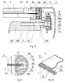
- Example 1 The tilting roller with guides, installed on the outer side of roof window, having the casing 1 for winding and storage of flexible screen 2 , further having two guides 3 connected perpendicularly to the casing 1 and located respectively on left and right side of the window 4 .
- the assembly of guides 3 and casing 1 may tilt, since the casing 1 is joined with the upper part of the frame 41 of the window 4 in articulating manner and the ends of guides 3 opposite the casing are connected with lower corners of the sash 42 of the window 4 which opens by rotation of the sash 42 around the hinges 43 located slightly above the half of the length of side members of window frame 41 .
- the guides 3 and casing 1 tilt, keeping pace with the rotating movement of lower part of the window sash 42 .
- guides 3 The purpose of guides 3 is to keep the flexible screen 2 stretched across the window 4 , i.e. in horizontal direction, regardless the position of the screen remaining stationary with respect to the casing 1 , and also guiding the screen edges along the window 4 during winding or unwinding of the screen.
- the casing 1 of the roller blind assembly is fixed to the frame 41 of the window 4 by mounting rail 11 having the form of box-shaped section and located on the upper member of window frame 41 and fastened to this frame by threaded fasteners.
- the casing 1 is connected with mounting rail 11 in articulated way by two (left and right) holders 12 located at respective ends of the casing.
- Each holder 12 consists of the base plate 12a and bearing plate 12b perpendicular to the base plate and having the bearing opening in which the casing 1 is seated in a pivoting manner.
- the holder 12 is fastened to the mounting rail 11 by inserting its base plate 12a under the angular rib 11a and engaging it with the flat rib of mounting rail 11 .
- the holder 12 is protected against inadvertent detachment from the mounting rail by the screw 12c which is mounted in the holder and whose head is pressed down to the retaining rib 11c of the mounting rail.
- This mounting solution allows for quick and easy mounting of the casing 1 with holders 12 on the mounting rail 11 previously fastened to the window frame 41 .
- the casing 1 is equipped with two bodies 13 , the left and the right one, located near its ends and playing a role of bearing assemblies which join the casing with guides 3 .
- each body 13 the cylindrical protrusion 13a is provided which is directed towards outside of the casing 1 and pivotably seated in the bearing plate 12b of the holder 12 by inserting it into the bearing opening equipped with four sliding inserts 12d made of polyamide plastic and arranged circumferentially in the bearing opening.
- the purpose of sliding inserts 12d is to reduce the resistance to motion of the cylindrical protrusion 13a inside the bearing opening and, in consequence, the resistance to rotational motion of the casing 1 with respect to holders 12 .
- the flexible screen 2 is made of fabric, particularly the fabric made of plastic guiding cavitiesfibres featuring with reduced light transmittance, and is resistant to rain and other weather factors.
- the screen is wound in the casing 1 on the shaft 5 arranged coaxially with bearing openings in bearing plates 12b of the holders 12 which fasten the casing 1 to the mounting rail 11 .
- the edge of flexible screen 2 unwound from the shaft 5 in the casing and parallel to this shaft is fixed in the transverse beam 21 having the ends 22 engaged in guides 3 perpendicular to the casing 1 and connected with bodies 13 of this casing.
- the ends 22 of transverse beam 21 move in guides 3 during winding or unwinding of the flexible screen 2 or remain stationary with respect to the guides when the screen stays in position set by the user.
- the guides 3 are arranged in the form of extruded metal sections with guiding cavities 31 facing each other and designed for taking in the ends 22 of sliding beam 21 .
- each guide the deeper part of guiding cavity 31 is arranged in the form of edge cavity 32 separated from guiding cavity by two ribs 33 located opposite to each other and separated with a gap.
- the slidable guiding insert 6 is provided made of polyamide material and having two angular ribs 61 located symmetrically in such arrangement that a longitudinal slot is formed between their bent arms facing each other. Through this slot the sliding tape 7 , which is lap connected with the edge of flexible screen 2 , goes into the slidable guiding insert.
- the catching elements of sliding tape 7 located inside the cavity 62 of the slidable guiding insert 6 are made in the form of continuous, oblong spatial loop structure made of plastic material.
- This structure is composed of small loops 72 perpendicular to the surface of tape 71 and mutually connected by longitudinal loops.
- Each transverse loop connects through the outer longitudinal loop 73 with the transverse loop 72 adjacent to it from the casing side, and through the inner longitudinal loop 74 with the transverse loop 72 adjacent to it on the side opposite with respect to the casing, i.e. on the side where the return assembly 34 is located at the end of the guide 3 .
- the outer longitudinal loops 72 and the inner longitudinal loops 73 are alternately arranged on both opposite surfaces of the tape 71 , being parallel and adherent to them, and are joined with the tape 71 by welding.
- the longitudinal loops are referred to as the inner ( 73 ) or the outer ( 72 ) ones based on their location with respect to the tape 71 , i.e. from the window side or the outer side, respectively.
- the wall located opposite the longitudinal slot and playing a role of the bottom of cavity in this guiding insert contain outer arms 63 which on both sides reach beyond the angular ribs 61 of the insert. Between the outer arms 63 of this wall and the ribs 61 which separate the edge cavity 32 from guiding cavity 31 the elastic inserts 64 are located, which are made of cellular rubber material and push the slidable guiding inserts 6 in both guides 3 towards outside.
- the oblong, continuous spatial loop structure may move in the cavity 62 of the guiding insert 6 only, and during unwinding of the flexible screen 2 the successive transversal loops 72 of the sliding tape 7 enter the cavity 62 from the face of slidable guiding insert 6 on the casing 1.
- the slidable guiding inserts 6 being pushed towards outside by elastic inserts 64 , pull the sliding tapes 7 and stretch the flexible screen 2 in the direction perpendicular to the unwinding direction, i.e. horizontally across the window 4 .
- the rewinding shaft 51 is provided which directs the flexible screen 2 into the guides 3 and the sliding tapes 7 attached to the screen edges into the slidable guiding inserts 6 in these guides. Locating the rewinding shaft 51 at the side where the flexible screen 2 leaves the casing 1 allows for shaping the cylindrical surface of the opposite side 14 of the casing (see Fig. 7 ) in such a way that the casing 1 together with guides 3 may tilt, and the entire assembly still features with compact structure and small outline dimensions.
- the rewinding shaft 1 is bearing mounted in both bodies 13 of the casing by its end necks 52 which engage in both bodies from the inner side, i.e. from the side directed to the opposite body.
- the necks 52 are located in sliding sleeves 53 , which in turn are inserted into bodies 13 from the outer side.
- the channel 13b is provided for the purpose of entering the neck 52 of the rewinding shaft to its seating position, and each channel 13b terminates with the seat 13c for the sliding sleeve 53 .
- the outer diameter of sleeve 53 is greater than the width of the channel 13b , therefore upon inserting the neck 52 into the seat 13c through the channel 13b and inserting the sliding sleeve 53 into the seat 13c with simultaneous sliding it over the neck 52 of rewinding shaft the shape-forced connection is obtained which allows rotational movements of rewinding shaft 51 in sliding sleeves 53 and simultaneously prevents the shaft from displacing.
- the sliding sleeve 53 is fixed in the body 13 by the cover 15 fastened to the body by screws and equipped with protruding part 15a which presses the flange of sliding sleeve against the retaining surface of the body.
- the sliding surface also has the spur 53a which is located in longitudinal groove cut in the seat for this sleeve provided in the body. This spur blocks the rotational movement of the sleeve with respect to the body, so as only the neck 52 slides in the sleeve 53 .
- the shaft 5 on which the flexible screen 2 is wound in the casing 1 is driven by electric motor 54 hidden inside this shaft.
- the face of motor 54 is fastened to the cover 15 by screws that pass through the holes 15b in the cover, and is also aligned with the cover by centring pin protruding from it and entering the seat 54a provided in the electric motor 54 .
- the movement of flexible screen 2 during unwinding, as well as stretching this screen along the window length is caused by the cords 8 which pass in guides 3 ; said cords move the transverse beam 21 away of the casing 1 .
- One end of the cord is fastened to and wound onto the reel 81 which is located in the casing 1 and rotates together with the shaft 5 when the latter winds the flexible screen 2 in such fashion that the cords 8 and flexible screen 2 winds in opposite directions, i.e. during unwinding of the screen the cord winds on the reel and, reversely, the cord unwinds from the reel during winding the screen on the shaft.
- the reels 81 on both sides of casing are driven by central part of the shaft 5 through splined connecting members 55 which have the central part of reduced diameter, thus leaving a space for sliding tape 7 wound on the shaft, particularly for the loop structure of the tape which is thicker than the flexible screen 2 .
- the other end of cord 8 is, upon passing over two return pulleys 82 mounted in the return assembly 34 located on the end of guide 3 , secured in the sliding beam 21 .
- the cord 8 runs through the angular cavity 35 in the guide 3 which has the access slot open towards the window frame 41 .
- the cord 8 runs through the guiding cavity 31 in the guide 3 .
- the cord 8 remains under the action of springloaded tensioning device 83 which takes up any slack of cord 8 resulting from different and varying winding diameters of the flexible screen 2 on the shaft 5 and the cords 8 on reels 81 .
- each guide 3 is also equipped with tilting guide 36 located in parallel to the main section of the guide 3 of the roller blind assembly.
- the tilting guide 36 is arranged in the form of channel section with ends of its arms bent towards each other and defining the cavity for the slide 37 which connects the guide 3 with lower corner of the sash 42 of the roof window 4 .
- the tilting guides 36 are so located in both guides 3 that their cavities for engaging the slides 37 are open towards each other.
- the tilting guide 36 connects with the main section of the guide 3 through the longitudinal, T-shaped spline 35a which is inserted to the T-slot in the main section from the face of guide 3 .
- the sash 42 of the window 4 is connected with tilting guide 36 through the pin 44 fastened to the cover plate 45 affixed to the window sash frame 42 .
- the pin 44 is made in the form of the cylindrical head screw threaded into the cover plate 45 . The head of this screw is inserted into the seat in the slide 37 and secured there against inadvertent disconnection of the pin 44 and the slide 37 by snap-locking connection.
- Example 2 The tilting roller blind with guides, installed on the outer side of roof window differs from the first exemplary embodiment of the invention in that that instead the slide the roller moves inside the tilting guide, and the diameter of this roller is greater than the width of access slot provided in the tilting guide cavity and open towards the opposite guide.
- the rollers which operate together with both guides are pivotably mounted on pins installed in the same way as in the first exemplary embodiment, in cover plates affixed to the corners of window sash. During assembly of guides the roller is inserted to the cavity in tilting guide from the face of this guide, prior to connecting the guide to the casing.
- Other components and parts of tilting roller blind, as well as the casing design, including the location of rewinding shaft are the same as in the first exemplary embodiment of the invention.
- Example 3 which does not belong to the present invention.
- the tilting roller blind with guides is installed on vertical window mounted in the building wall.
- the casing is fixed to the top member of the window frame.
- the short tilting guides are provided which operate together with articulated connecting members pivotably mounted to the lower part of window frame and terminated with rollers placed in tilting guides.
- Other components and parts of tilting roller blind, including the solution for guiding of flexible screen edges and the design of casing with location of rewinding shaft are identical as in the first exemplary embodiment of the invention.
Claims (10)
- Dachfenstersatz, bestehend aus einem Dachfenster (4) mit Fensterrahmen (41) sowie aus einem Fensterflügel (42), zu diesem Satz gehört auch ein kippbarer Rollladen mit den Führungsschienen (3, 36) insbesondere für das Dachfenster, und zwar insbesondere ein Rollladen, der außen am Fenster (4) montiert wird, das durch die Drehung des Flügels (42) rundum die horizontale Achse, die oberhalb der Hälfte der Flügelhöhe angebracht ist, geöffnet wird; der kippbare Rollladen enthält einen flexiblen Vorhang (2), auf der Welle (5) umwickelt, die zum Aufwickeln dieses Vorhangs (2) dient und durch einen Motor (54), insbesondere einen Elektromotor, angetrieben wird, der Vorhang (2) wird mit einem verschiebbaren Träger (21) beendet, dessen Enden in den Führungsschienen (3) des Vorhangs geführt werden; der Satz hat auch eine kippbar befestigte Kassette (1), die insbesondere auf dem oberen Rahmenholz des Fensterrahmens (41) befestigt ist und in eben dieser Kassette der flexible Vorhang (2) im aufgewickelten Zustand aufbewahrt wird, wobei die Führungsschienen (3) des Vorhangs Profile sind, die zu sich geöffnete Führungsnischen (31) für die Enden des verschiebbaren Trägers (21) und Randnischen (32) zum Führen der Ränder des flexiblen Vorhangs (2) haben; darüber hinaus hat der Rollladen Neigungsführungsschienen (36), die mit den zur Kassette (1) gegenüberliegenden Ecken des Fensterflügels verbunden sind, was bewirkt, dass während des Öffnens und Schließens des Fensters die Baugruppe der Führungsschienen (3, 36) geneigt wird, vorzugsweise mit der Kassette (1), darüber hinaus sind in den Randnischen (32) Gleitführungseinlagen (6), vorzugsweise aus Kunststoff, die jeweils zwei angewinkelte Rippen (61) haben, die symmetrisch so angeordnet sind, dass zwischen ihren zu sich gerichteten Arme ein länglicher Spalt ist, und an den Rändern des flexiblen Vorhangs (2) in regelmäßigen Abständen Haken befestigt werden, deren Greifelemente (72), mit einer Breite, die größer als die Breite dieses Spaltes ist, sich im Innern der Gleitführungseinlage (6) verlagern, und die Einengungen der Haken gehen durch den Spalt zwischen den angewinkelten Rippen dieser Einlage, die Enden (22) des verschiebbaren Trägers (21) dagegen werden bei seiner Fortbewegung von der Kassette (1), angetrieben durch Seilzüge (8) und aufgerollt auf die in der Kassette angeordneten Wickler (81) sowie umwickelt durch die Umlenkrollen (82), die an den zur Kassette gegenüberliegenden Enden der Führungsschienen angeordnet sind.
- Der Dachfenstersatz nach Anspruch 1, dadurch gekennzeichnet, dass die Randnische (32) vom Bewegungsraum des flexiblen Vorhangs (2) abgetrennt ist, und zwar durch die einander gegenüberliegend angeordneten Rippen (33), zwischen denen sich ein länglicher Spalt befindet, dessen Breite etwas größer als der Abstand zwischen den Außenflächen der angewinkelten Rippen (61) der Gleitführungseinlage (6) ist.
- Der Dachfenstersatz nach Anspruch 1, oder 2, dadurch gekennzeichnet, dass die Randnische (62) für die Führung des Randes des flexiblen Vorhangs (2) ein tieferer Teil der Führungsnische (31) für den verschiebbaren Träger (21) ist, der von dieser Nische durch zwei einander gegenüberliegend angeordneten Rippen (33) getrennt ist.
- Der Dachfenstersatz nach einem der Ansprüche 1 bis 3, dadurch gekennzeichnet, dass die Hakenbaugruppen, die mit der Gleitführungseinlage zusammenarbeiten, die Form von Schiebebändern (7) haben, die an den flexiblen Vorhang (2) längs seiner beiden Ränder befestigt sind, wobei die Greifelemente eines jeden Schiebebandes, die am äußeren Rand dieses Bandes angeordnet und im Innern der Gleitführungseinlage angebracht sind, die Form einer räumlichen, kontinuierlichen und länglichen Schleifenkonstruktion haben, vorzugsweise gefertigt aus Kunststoff, die Querschleifen (72) gegenüber der Fläche des Bandes (71) enthält, und zwar so mit den Längsschleifen verbunden, dass jede Querschleife mittels der einen Längsschleife (73) mit einer ihr benachbarten Querschleife an der Seite der Kassette verbunden ist, und mittels der zweiten Längsschleife (74) mit der ihr benachbarten Querschleife an der gegenüberliegenden Seite verbunden ist, wobei die Längsschleifen abwechselnd an beiden gegenüberliegenden Flächen des Bandes (71), parallel zu diesen Flächen, angeordnet und mit dem Band (71) verbunden sind.
- Der Dachfenstersatz nach einem der Ansprüche 2 bis 4, dadurch gekennzeichnet, dass die Wand der Gleitführungseinlage (6), gegenüberliegend zum Spalt, Außenabschnitte (63) hat, die außerhalb der angewinkelten Rippen (61) dieser Einlage von beiden Seiten hervorstehen, und zwischen den Außenabschnitten dieser Wand und den Rippen (33), welche die Randnische (32) vom Bewegungsraum des flexiblen Vorhangs trennen, Federeinsätze sind (64), vorzugsweise aus Zellgummi, die den flexiblen Vorhang (2) senkrecht zu seiner Ausrollrichtung anspannen.
- Der Dachfenstersatz nach einem der Ansprüche 1 bis 5, dadurch gekennzeichnet, dass er in der Kassette (1) eine Umwickelachse hat (51), die an der Seite des Ausgangs des flexiblen Vorhangs (2) von der Kassette (1) zu den Randnischen (32) in den Führungsschienen (3) angeordnet ist und in den Gehäusen gelagert ist (13), die sich an beiden Enden der Kassette (1) befinden und diese Kassette mit den Führungsschienen (3) verbinden.
- Der Dachfenstersatz nach Anspruch 6, dadurch gekennzeichnet, dass die Umwickelachse (51) in den Gleithülsen (53), die in die Gehäuse (13) von außen eingeschoben werden, gelagert ist, und in jedem dieser Gehäuse ist ein Kanal (13b) zum Einführen des Zapfens (51) der Umwickelachse, der wiederum mit einer Buchse (13c) für die Gleithülse (53) endet, deren Durchmesser größer ist als die Breite des Kanals.
- Der Dachfenstersatz nach einem der Ansprüche 1 bis 7, dadurch gekennzeichnet, dass die Neigungsführungsschienen (36) Nischen für die Verlagerung der Elemente in ihnen haben, die diese Führungsschienen mit den unteren Ecken des Fensterflügels verbinden, und das verbindende Element der Zapfen (44) ist, vorzugsweise befestigt in der Lasche (45), die am Rahmen des Fensterflügels (52) befestigt ist, und zwar drehbar verbunden mit dem Schieber (37), der sich in der Nische der Neigungsführungsschiene (36) verlagert, wobei der Zapfen (44) in der Buchse dieses Schiebers (37) angeordnet ist und durch eine Schnappverbindung geschützt wird.
- Der Dachfenstersatz nach einem der Ansprüche 1 bis 8, dadurch gekennzeichnet, dass das Profil der Führungsschiene (3) eine Winkelnische (35) hat, die auf der zur Führungsnische (31) gegenüberliegenden Seite angeordnet ist, und in der Winkelnische verlagert sich ein Abschnitt des Seilzuges (8), weit gespannt zwischen dem Wickler (81) in der Kassette (1) und dem Umkehrelement (34), in dem vorzugsweise zwei Umlenkrollen (82) sind, und der Eingangsspalt der Winkelnische (35) von der Seite des Fensterrahmens geöffnet ist.
- Der Dachfenstersatz nach Anspruch 9, dadurch gekennzeichnet, dass die Seilzüge (8), die den verschiebbaren Träger (21) in Bewegung antreiben, die ihn weiter von der Kassette (1) entfernen sowie mit der Baugruppe des Spanners (83) zusammenarbeiten, insbesondere in Form von Federn, die im verschiebbaren Träger angeordnet sind.
Applications Claiming Priority (1)
| Application Number | Priority Date | Filing Date | Title |
|---|---|---|---|
| PL400631A PL221436B1 (pl) | 2012-09-03 | 2012-09-03 | Roleta przechylna z prowadnicami, zwłaszcza dla okna dachowego |
Publications (3)
| Publication Number | Publication Date |
|---|---|
| EP2703595A2 EP2703595A2 (de) | 2014-03-05 |
| EP2703595A3 EP2703595A3 (de) | 2015-05-27 |
| EP2703595B1 true EP2703595B1 (de) | 2016-02-24 |
Family
ID=49084720
Family Applications (1)
| Application Number | Title | Priority Date | Filing Date |
|---|---|---|---|
| EP13004211.2A Revoked EP2703595B1 (de) | 2012-09-03 | 2013-08-27 | Neigbarer Rollladen mit Führungsleisten für Dachfenster |
Country Status (2)
| Country | Link |
|---|---|
| EP (1) | EP2703595B1 (de) |
| PL (1) | PL221436B1 (de) |
Families Citing this family (4)
| Publication number | Priority date | Publication date | Assignee | Title |
|---|---|---|---|---|
| EP3015637B1 (de) * | 2014-10-29 | 2019-04-17 | VKR Holding A/S | Abschirmvorrichtung für ein dachfenster sowie verfahren zur montage solch einer abschirmvorrichtung auf einem dachfenster |
| DE102015116287A1 (de) * | 2015-09-25 | 2017-03-30 | Reiner Detenhoff | Schwenklager einer Führung für einen ausstellbaren Rollladen und schwenkbar gelagerte Rollladenführung |
| PL240870B1 (pl) * | 2017-08-07 | 2022-06-20 | Fakro Pp Spolka Z Ograniczona Odpowiedzialnoscia | Zespół napędowy rolety, zwłaszcza listwowej |
| EP3959410A1 (de) * | 2019-11-25 | 2022-03-02 | VKR Holding A/S | Sichtschutzanordnung mit einer abschirmvorrichtung |
Citations (14)
| Publication number | Priority date | Publication date | Assignee | Title |
|---|---|---|---|---|
| JP2001107666A (ja) | 1999-10-05 | 2001-04-17 | Hayashiguchi Kogyo Kk | ロールスクリーン用のスクリーンおよびロールスクリーン |
| DE102006020573A1 (de) | 2006-05-01 | 2007-11-15 | Mallmann, Hans-Jürgen | Flexibles Abdeckmittel wie Markise oder Verdunkelung mit vertikaler- und horizontaler Spannung des Abdeckmittels |
| BE1017146A3 (nl) | 2005-05-24 | 2008-03-04 | Vero Duco Nv | Scherminrichting met een aan weerszijden van een geleiding voorzien scherm. |
| DE202009003723U1 (de) | 2009-03-09 | 2009-05-28 | J. Paul Gmbh | Schutzvorrichtung für eine Tür- oder Fensteranordnung eines Gebäudes |
| BE1017767A5 (nl) | 2007-09-26 | 2009-06-02 | Renson Ventilation Nv | Scherminrichting. |
| WO2009098433A1 (en) | 2008-02-07 | 2009-08-13 | Licciardi Di Stefano, Carmelo, Joseph | Screen system with a bracket for mounting a guiding rail |
| EP2157275A2 (de) | 2008-07-24 | 2010-02-24 | Kestelyn NV | Bildschirmvorrichtung |
| EP1669537B1 (de) | 2004-12-10 | 2010-03-24 | Corradi S.P.A. | Führungseinrichtung für aufrollbare Stores |
| EP2236731A2 (de) | 2009-03-13 | 2010-10-06 | Hunter Douglas Industries B.V. | Abdeckung für architektonische Öffnungen |
| CH702041B1 (de) | 2008-03-07 | 2011-04-29 | Storama Ag Fuer Sonnen Und Wetterschutz Technik | Führungsschiene für Sonnenstore. |
| CN201883916U (zh) | 2010-12-03 | 2011-06-29 | 栗秀梅 | 纱窗防风装置 |
| US20120012260A1 (en) | 2010-07-16 | 2012-01-19 | Leonard Elinson | Retractable shade assembly with adjustable side guides |
| WO2012050518A1 (en) | 2010-10-15 | 2012-04-19 | Erco Systems Ab | Window screen device |
| KR200460972Y1 (ko) | 2009-09-29 | 2012-06-21 | 민인영 | 차양막 이탈방지장치 |
Family Cites Families (9)
| Publication number | Priority date | Publication date | Assignee | Title |
|---|---|---|---|---|
| PL109561B2 (en) | 1978-03-15 | 1980-06-30 | Inst Chem Przerobki Wegla | Method of hardening coal-containing materials,especially briquettes |
| FR2595403B1 (fr) * | 1986-03-05 | 1990-08-10 | Diruy Sa | Dispositif de projection d'un volet roulant et volet pourvu de ce dispositif |
| GB2235005B (en) | 1989-08-03 | 1993-11-24 | Seizo Hayashiguchi | Screen |
| JPH0797886A (ja) | 1993-08-05 | 1995-04-11 | Hayashiguchi Kogyo Kk | スクリーン装置 |
| CN1211562C (zh) | 2000-07-13 | 2005-07-20 | Vkr控股公司 | 遮蔽装置 |
| WO2006074654A1 (en) | 2005-01-11 | 2006-07-20 | Vkr Holding A/S | Screening arrangement and a method for installing |
| DE102009007682B4 (de) | 2009-02-05 | 2013-03-07 | Roma Kg | Vorrichtung zum Verschließen einer Gebäudeöffnung |
| DE202009002343U1 (de) | 2009-02-18 | 2010-07-08 | Brichta Gmbh | Verdunklungs- oder Abschirmungsvorhang und Verdunklungs- oder Abschirmungsvorrichtung |
| DE202011100039U1 (de) * | 2011-04-29 | 2011-06-22 | Roma Kg, 89331 | Verschattungsvorrichtung |
-
2012
- 2012-09-03 PL PL400631A patent/PL221436B1/pl unknown
-
2013
- 2013-08-27 EP EP13004211.2A patent/EP2703595B1/de not_active Revoked
Patent Citations (14)
| Publication number | Priority date | Publication date | Assignee | Title |
|---|---|---|---|---|
| JP2001107666A (ja) | 1999-10-05 | 2001-04-17 | Hayashiguchi Kogyo Kk | ロールスクリーン用のスクリーンおよびロールスクリーン |
| EP1669537B1 (de) | 2004-12-10 | 2010-03-24 | Corradi S.P.A. | Führungseinrichtung für aufrollbare Stores |
| BE1017146A3 (nl) | 2005-05-24 | 2008-03-04 | Vero Duco Nv | Scherminrichting met een aan weerszijden van een geleiding voorzien scherm. |
| DE102006020573A1 (de) | 2006-05-01 | 2007-11-15 | Mallmann, Hans-Jürgen | Flexibles Abdeckmittel wie Markise oder Verdunkelung mit vertikaler- und horizontaler Spannung des Abdeckmittels |
| BE1017767A5 (nl) | 2007-09-26 | 2009-06-02 | Renson Ventilation Nv | Scherminrichting. |
| WO2009098433A1 (en) | 2008-02-07 | 2009-08-13 | Licciardi Di Stefano, Carmelo, Joseph | Screen system with a bracket for mounting a guiding rail |
| CH702041B1 (de) | 2008-03-07 | 2011-04-29 | Storama Ag Fuer Sonnen Und Wetterschutz Technik | Führungsschiene für Sonnenstore. |
| EP2157275A2 (de) | 2008-07-24 | 2010-02-24 | Kestelyn NV | Bildschirmvorrichtung |
| DE202009003723U1 (de) | 2009-03-09 | 2009-05-28 | J. Paul Gmbh | Schutzvorrichtung für eine Tür- oder Fensteranordnung eines Gebäudes |
| EP2236731A2 (de) | 2009-03-13 | 2010-10-06 | Hunter Douglas Industries B.V. | Abdeckung für architektonische Öffnungen |
| KR200460972Y1 (ko) | 2009-09-29 | 2012-06-21 | 민인영 | 차양막 이탈방지장치 |
| US20120012260A1 (en) | 2010-07-16 | 2012-01-19 | Leonard Elinson | Retractable shade assembly with adjustable side guides |
| WO2012050518A1 (en) | 2010-10-15 | 2012-04-19 | Erco Systems Ab | Window screen device |
| CN201883916U (zh) | 2010-12-03 | 2011-06-29 | 栗秀梅 | 纱窗防风装置 |
Also Published As
| Publication number | Publication date |
|---|---|
| PL221436B1 (pl) | 2016-04-29 |
| PL400631A1 (pl) | 2014-03-17 |
| EP2703595A3 (de) | 2015-05-27 |
| EP2703595A2 (de) | 2014-03-05 |
Similar Documents
| Publication | Publication Date | Title |
|---|---|---|
| EP1640554B1 (de) | Hochkurbelbare abschirmvorrichtung | |
| JP3163685U (ja) | ブラインドシステム | |
| US10047558B2 (en) | Retractable flexible-panel door | |
| US6186212B1 (en) | Screen device | |
| NL2020963B1 (en) | Bottom rail assembly for a covering with adjustable roller position and related methods | |
| US5287908A (en) | Window covering assembly | |
| US9670721B2 (en) | Guide arrangement for hangings | |
| EP2703595B1 (de) | Neigbarer Rollladen mit Führungsleisten für Dachfenster | |
| US8991469B2 (en) | Light blocking slatted blind | |
| US20120012260A1 (en) | Retractable shade assembly with adjustable side guides | |
| TWI503240B (zh) | 天窗窗簾拉力維持装置 | |
| WO2018232439A1 (en) | RETRACTABLE SCREEN SYSTEM WHICH CAN BE LOW PROFILE RETROMPOSED | |
| US20190048659A1 (en) | Screen device | |
| US20140238622A1 (en) | Systems and methods for tilting a blind slat | |
| US6935398B2 (en) | Operating unit for a window covering | |
| AU2022333247A1 (en) | Architectural opening covering | |
| JPH081654U (ja) | 巻取式スクリーン装置 | |
| EP2650463B1 (de) | Außenrollladen mit Führungsschienen für Dachfenster und seine Montage | |
| AU2020100049A4 (en) | A low profile retrofitable retractable screen system | |
| JP3855226B2 (ja) | 巻取自在の面体装置 | |
| KR200435387Y1 (ko) | 시스템 창호용 롤러블라인드 | |
| GB2501797A (en) | Screen Assembly | |
| KR20110004507U (ko) | 블라인드 시스템 | |
| JP2007063943A (ja) | 幕体開閉装置及び幕体開閉方法 | |
| JP2004150167A (ja) | 開閉装置 |
Legal Events
| Date | Code | Title | Description |
|---|---|---|---|
| 17P | Request for examination filed |
Effective date: 20130903 |
|
| AK | Designated contracting states |
Kind code of ref document: A2 Designated state(s): AL AT BE BG CH CY CZ DE DK EE ES FI FR GB GR HR HU IE IS IT LI LT LU LV MC MK MT NL NO PL PT RO RS SE SI SK SM TR |
|
| AX | Request for extension of the european patent |
Extension state: BA ME |
|
| PUAI | Public reference made under article 153(3) epc to a published international application that has entered the european phase |
Free format text: ORIGINAL CODE: 0009012 |
|
| PUAL | Search report despatched |
Free format text: ORIGINAL CODE: 0009013 |
|
| AK | Designated contracting states |
Kind code of ref document: A3 Designated state(s): AL AT BE BG CH CY CZ DE DK EE ES FI FR GB GR HR HU IE IS IT LI LT LU LV MC MK MT NL NO PL PT RO RS SE SI SK SM TR |
|
| AX | Request for extension of the european patent |
Extension state: BA ME |
|
| RIC1 | Information provided on ipc code assigned before grant |
Ipc: E06B 9/24 20060101AFI20150423BHEP Ipc: E04F 10/06 20060101ALI20150423BHEP Ipc: E06B 9/42 20060101ALI20150423BHEP Ipc: E06B 9/58 20060101ALI20150423BHEP Ipc: E04D 13/035 20060101ALI20150423BHEP Ipc: E06B 9/72 20060101ALI20150423BHEP Ipc: E06B 9/92 20060101ALI20150423BHEP |
|
| 17Q | First examination report despatched |
Effective date: 20150512 |
|
| TPAC | Observations filed by third parties |
Free format text: ORIGINAL CODE: EPIDOSNTIPA |
|
| GRAP | Despatch of communication of intention to grant a patent |
Free format text: ORIGINAL CODE: EPIDOSNIGR1 |
|
| GRAS | Grant fee paid |
Free format text: ORIGINAL CODE: EPIDOSNIGR3 |
|
| INTG | Intention to grant announced |
Effective date: 20151111 |
|
| GRAA | (expected) grant |
Free format text: ORIGINAL CODE: 0009210 |
|
| STAA | Information on the status of an ep patent application or granted ep patent |
Free format text: STATUS: THE PATENT HAS BEEN GRANTED |
|
| AK | Designated contracting states |
Kind code of ref document: B1 Designated state(s): AL AT BE BG CH CY CZ DE DK EE ES FI FR GB GR HR HU IE IS IT LI LT LU LV MC MK MT NL NO PL PT RO RS SE SI SK SM TR |
|
| REG | Reference to a national code |
Ref country code: GB Ref legal event code: FG4D |
|
| REG | Reference to a national code |
Ref country code: CH Ref legal event code: EP |
|
| REG | Reference to a national code |
Ref country code: AT Ref legal event code: REF Ref document number: 776845 Country of ref document: AT Kind code of ref document: T Effective date: 20160315 |
|
| REG | Reference to a national code |
Ref country code: IE Ref legal event code: FG4D |
|
| REG | Reference to a national code |
Ref country code: DE Ref legal event code: R096 Ref document number: 602013005095 Country of ref document: DE |
|
| REG | Reference to a national code |
Ref country code: LT Ref legal event code: MG4D |
|
| REG | Reference to a national code |
Ref country code: NL Ref legal event code: MP Effective date: 20160224 |
|
| REG | Reference to a national code |
Ref country code: AT Ref legal event code: MK05 Ref document number: 776845 Country of ref document: AT Kind code of ref document: T Effective date: 20160224 |
|
| PG25 | Lapsed in a contracting state [announced via postgrant information from national office to epo] |
Ref country code: ES Free format text: LAPSE BECAUSE OF FAILURE TO SUBMIT A TRANSLATION OF THE DESCRIPTION OR TO PAY THE FEE WITHIN THE PRESCRIBED TIME-LIMIT Effective date: 20160224 Ref country code: HR Free format text: LAPSE BECAUSE OF FAILURE TO SUBMIT A TRANSLATION OF THE DESCRIPTION OR TO PAY THE FEE WITHIN THE PRESCRIBED TIME-LIMIT Effective date: 20160224 Ref country code: GR Free format text: LAPSE BECAUSE OF FAILURE TO SUBMIT A TRANSLATION OF THE DESCRIPTION OR TO PAY THE FEE WITHIN THE PRESCRIBED TIME-LIMIT Effective date: 20160525 Ref country code: NO Free format text: LAPSE BECAUSE OF FAILURE TO SUBMIT A TRANSLATION OF THE DESCRIPTION OR TO PAY THE FEE WITHIN THE PRESCRIBED TIME-LIMIT Effective date: 20160524 Ref country code: IT Free format text: LAPSE BECAUSE OF FAILURE TO SUBMIT A TRANSLATION OF THE DESCRIPTION OR TO PAY THE FEE WITHIN THE PRESCRIBED TIME-LIMIT Effective date: 20160224 Ref country code: FI Free format text: LAPSE BECAUSE OF FAILURE TO SUBMIT A TRANSLATION OF THE DESCRIPTION OR TO PAY THE FEE WITHIN THE PRESCRIBED TIME-LIMIT Effective date: 20160224 |
|
| REG | Reference to a national code |
Ref country code: FR Ref legal event code: PLFP Year of fee payment: 4 |
|
| PG25 | Lapsed in a contracting state [announced via postgrant information from national office to epo] |
Ref country code: PL Free format text: LAPSE BECAUSE OF FAILURE TO SUBMIT A TRANSLATION OF THE DESCRIPTION OR TO PAY THE FEE WITHIN THE PRESCRIBED TIME-LIMIT Effective date: 20160224 Ref country code: AT Free format text: LAPSE BECAUSE OF FAILURE TO SUBMIT A TRANSLATION OF THE DESCRIPTION OR TO PAY THE FEE WITHIN THE PRESCRIBED TIME-LIMIT Effective date: 20160224 Ref country code: RS Free format text: LAPSE BECAUSE OF FAILURE TO SUBMIT A TRANSLATION OF THE DESCRIPTION OR TO PAY THE FEE WITHIN THE PRESCRIBED TIME-LIMIT Effective date: 20160224 Ref country code: LV Free format text: LAPSE BECAUSE OF FAILURE TO SUBMIT A TRANSLATION OF THE DESCRIPTION OR TO PAY THE FEE WITHIN THE PRESCRIBED TIME-LIMIT Effective date: 20160224 Ref country code: NL Free format text: LAPSE BECAUSE OF FAILURE TO SUBMIT A TRANSLATION OF THE DESCRIPTION OR TO PAY THE FEE WITHIN THE PRESCRIBED TIME-LIMIT Effective date: 20160224 Ref country code: LT Free format text: LAPSE BECAUSE OF FAILURE TO SUBMIT A TRANSLATION OF THE DESCRIPTION OR TO PAY THE FEE WITHIN THE PRESCRIBED TIME-LIMIT Effective date: 20160224 Ref country code: SE Free format text: LAPSE BECAUSE OF FAILURE TO SUBMIT A TRANSLATION OF THE DESCRIPTION OR TO PAY THE FEE WITHIN THE PRESCRIBED TIME-LIMIT Effective date: 20160224 Ref country code: PT Free format text: LAPSE BECAUSE OF FAILURE TO SUBMIT A TRANSLATION OF THE DESCRIPTION OR TO PAY THE FEE WITHIN THE PRESCRIBED TIME-LIMIT Effective date: 20160624 |
|
| PG25 | Lapsed in a contracting state [announced via postgrant information from national office to epo] |
Ref country code: DK Free format text: LAPSE BECAUSE OF FAILURE TO SUBMIT A TRANSLATION OF THE DESCRIPTION OR TO PAY THE FEE WITHIN THE PRESCRIBED TIME-LIMIT Effective date: 20160224 Ref country code: EE Free format text: LAPSE BECAUSE OF FAILURE TO SUBMIT A TRANSLATION OF THE DESCRIPTION OR TO PAY THE FEE WITHIN THE PRESCRIBED TIME-LIMIT Effective date: 20160224 |
|
| REG | Reference to a national code |
Ref country code: DE Ref legal event code: R026 Ref document number: 602013005095 Country of ref document: DE |
|
| PG25 | Lapsed in a contracting state [announced via postgrant information from national office to epo] |
Ref country code: SK Free format text: LAPSE BECAUSE OF FAILURE TO SUBMIT A TRANSLATION OF THE DESCRIPTION OR TO PAY THE FEE WITHIN THE PRESCRIBED TIME-LIMIT Effective date: 20160224 Ref country code: CZ Free format text: LAPSE BECAUSE OF FAILURE TO SUBMIT A TRANSLATION OF THE DESCRIPTION OR TO PAY THE FEE WITHIN THE PRESCRIBED TIME-LIMIT Effective date: 20160224 Ref country code: RO Free format text: LAPSE BECAUSE OF FAILURE TO SUBMIT A TRANSLATION OF THE DESCRIPTION OR TO PAY THE FEE WITHIN THE PRESCRIBED TIME-LIMIT Effective date: 20160224 Ref country code: SM Free format text: LAPSE BECAUSE OF FAILURE TO SUBMIT A TRANSLATION OF THE DESCRIPTION OR TO PAY THE FEE WITHIN THE PRESCRIBED TIME-LIMIT Effective date: 20160224 |
|
| PLBI | Opposition filed |
Free format text: ORIGINAL CODE: 0009260 |
|
| PG25 | Lapsed in a contracting state [announced via postgrant information from national office to epo] |
Ref country code: BE Free format text: LAPSE BECAUSE OF FAILURE TO SUBMIT A TRANSLATION OF THE DESCRIPTION OR TO PAY THE FEE WITHIN THE PRESCRIBED TIME-LIMIT Effective date: 20160224 |
|
| 26 | Opposition filed |
Opponent name: VKR-HOLDING A/S Effective date: 20161124 |
|
| PLAX | Notice of opposition and request to file observation + time limit sent |
Free format text: ORIGINAL CODE: EPIDOSNOBS2 |
|
| PG25 | Lapsed in a contracting state [announced via postgrant information from national office to epo] |
Ref country code: SI Free format text: LAPSE BECAUSE OF FAILURE TO SUBMIT A TRANSLATION OF THE DESCRIPTION OR TO PAY THE FEE WITHIN THE PRESCRIBED TIME-LIMIT Effective date: 20160224 Ref country code: BG Free format text: LAPSE BECAUSE OF FAILURE TO SUBMIT A TRANSLATION OF THE DESCRIPTION OR TO PAY THE FEE WITHIN THE PRESCRIBED TIME-LIMIT Effective date: 20160524 |
|
| PG25 | Lapsed in a contracting state [announced via postgrant information from national office to epo] |
Ref country code: MC Free format text: LAPSE BECAUSE OF FAILURE TO SUBMIT A TRANSLATION OF THE DESCRIPTION OR TO PAY THE FEE WITHIN THE PRESCRIBED TIME-LIMIT Effective date: 20160224 |
|
| REG | Reference to a national code |
Ref country code: CH Ref legal event code: PL |
|
| PG25 | Lapsed in a contracting state [announced via postgrant information from national office to epo] |
Ref country code: LI Free format text: LAPSE BECAUSE OF NON-PAYMENT OF DUE FEES Effective date: 20160831 Ref country code: CH Free format text: LAPSE BECAUSE OF NON-PAYMENT OF DUE FEES Effective date: 20160831 |
|
| PLBB | Reply of patent proprietor to notice(s) of opposition received |
Free format text: ORIGINAL CODE: EPIDOSNOBS3 |
|
| REG | Reference to a national code |
Ref country code: IE Ref legal event code: MM4A |
|
| REG | Reference to a national code |
Ref country code: FR Ref legal event code: PLFP Year of fee payment: 5 |
|
| PG25 | Lapsed in a contracting state [announced via postgrant information from national office to epo] |
Ref country code: IE Free format text: LAPSE BECAUSE OF NON-PAYMENT OF DUE FEES Effective date: 20160827 |
|
| PG25 | Lapsed in a contracting state [announced via postgrant information from national office to epo] |
Ref country code: LU Free format text: LAPSE BECAUSE OF NON-PAYMENT OF DUE FEES Effective date: 20160827 |
|
| PG25 | Lapsed in a contracting state [announced via postgrant information from national office to epo] |
Ref country code: CY Free format text: LAPSE BECAUSE OF FAILURE TO SUBMIT A TRANSLATION OF THE DESCRIPTION OR TO PAY THE FEE WITHIN THE PRESCRIBED TIME-LIMIT Effective date: 20160224 Ref country code: HU Free format text: LAPSE BECAUSE OF FAILURE TO SUBMIT A TRANSLATION OF THE DESCRIPTION OR TO PAY THE FEE WITHIN THE PRESCRIBED TIME-LIMIT; INVALID AB INITIO Effective date: 20130827 |
|
| PG25 | Lapsed in a contracting state [announced via postgrant information from national office to epo] |
Ref country code: IS Free format text: LAPSE BECAUSE OF FAILURE TO SUBMIT A TRANSLATION OF THE DESCRIPTION OR TO PAY THE FEE WITHIN THE PRESCRIBED TIME-LIMIT Effective date: 20160224 Ref country code: TR Free format text: LAPSE BECAUSE OF FAILURE TO SUBMIT A TRANSLATION OF THE DESCRIPTION OR TO PAY THE FEE WITHIN THE PRESCRIBED TIME-LIMIT Effective date: 20160224 Ref country code: MT Free format text: LAPSE BECAUSE OF NON-PAYMENT OF DUE FEES Effective date: 20160831 Ref country code: MK Free format text: LAPSE BECAUSE OF FAILURE TO SUBMIT A TRANSLATION OF THE DESCRIPTION OR TO PAY THE FEE WITHIN THE PRESCRIBED TIME-LIMIT Effective date: 20160224 |
|
| PLCK | Communication despatched that opposition was rejected |
Free format text: ORIGINAL CODE: EPIDOSNREJ1 |
|
| STAA | Information on the status of an ep patent application or granted ep patent |
Free format text: STATUS: THE PATENT HAS BEEN GRANTED |
|
| REG | Reference to a national code |
Ref country code: FR Ref legal event code: PLFP Year of fee payment: 6 |
|
| APBM | Appeal reference recorded |
Free format text: ORIGINAL CODE: EPIDOSNREFNO |
|
| APBP | Date of receipt of notice of appeal recorded |
Free format text: ORIGINAL CODE: EPIDOSNNOA2O |
|
| APAH | Appeal reference modified |
Free format text: ORIGINAL CODE: EPIDOSCREFNO |
|
| PG25 | Lapsed in a contracting state [announced via postgrant information from national office to epo] |
Ref country code: AL Free format text: LAPSE BECAUSE OF FAILURE TO SUBMIT A TRANSLATION OF THE DESCRIPTION OR TO PAY THE FEE WITHIN THE PRESCRIBED TIME-LIMIT Effective date: 20160224 |
|
| APBQ | Date of receipt of statement of grounds of appeal recorded |
Free format text: ORIGINAL CODE: EPIDOSNNOA3O |
|
| PGFP | Annual fee paid to national office [announced via postgrant information from national office to epo] |
Ref country code: GB Payment date: 20190710 Year of fee payment: 7 |
|
| GBPC | Gb: european patent ceased through non-payment of renewal fee |
Effective date: 20200827 |
|
| PG25 | Lapsed in a contracting state [announced via postgrant information from national office to epo] |
Ref country code: GB Free format text: LAPSE BECAUSE OF NON-PAYMENT OF DUE FEES Effective date: 20200827 |
|
| REG | Reference to a national code |
Ref country code: DE Ref legal event code: R103 Ref document number: 602013005095 Country of ref document: DE Ref country code: DE Ref legal event code: R064 Ref document number: 602013005095 Country of ref document: DE |
|
| APBU | Appeal procedure closed |
Free format text: ORIGINAL CODE: EPIDOSNNOA9O |
|
| PGFP | Annual fee paid to national office [announced via postgrant information from national office to epo] |
Ref country code: DE Payment date: 20220830 Year of fee payment: 10 |
|
| RDAF | Communication despatched that patent is revoked |
Free format text: ORIGINAL CODE: EPIDOSNREV1 |
|
| STAA | Information on the status of an ep patent application or granted ep patent |
Free format text: STATUS: PATENT REVOKED |
|
| RDAG | Patent revoked |
Free format text: ORIGINAL CODE: 0009271 |
|
| PGFP | Annual fee paid to national office [announced via postgrant information from national office to epo] |
Ref country code: FR Payment date: 20220715 Year of fee payment: 10 |
|
| 27W | Patent revoked |
Effective date: 20220930 |
|
| P01 | Opt-out of the competence of the unified patent court (upc) registered |
Effective date: 20230419 |