EP2700373A1 - Maschinenlernen beim bei der Bestimmung des Katheterelektrodenkontakts - Google Patents
Maschinenlernen beim bei der Bestimmung des Katheterelektrodenkontakts Download PDFInfo
- Publication number
- EP2700373A1 EP2700373A1 EP13180877.6A EP13180877A EP2700373A1 EP 2700373 A1 EP2700373 A1 EP 2700373A1 EP 13180877 A EP13180877 A EP 13180877A EP 2700373 A1 EP2700373 A1 EP 2700373A1
- Authority
- EP
- European Patent Office
- Prior art keywords
- contact state
- contact
- determinations
- electrode
- designation
- Prior art date
- Legal status (The legal status is an assumption and is not a legal conclusion. Google has not performed a legal analysis and makes no representation as to the accuracy of the status listed.)
- Granted
Links
- 238000010801 machine learning Methods 0.000 title 1
- 210000002216 heart Anatomy 0.000 claims abstract description 24
- 238000002679 ablation Methods 0.000 claims description 41
- 230000037431 insertion Effects 0.000 claims 1
- 238000003780 insertion Methods 0.000 claims 1
- 230000000007 visual effect Effects 0.000 claims 1
- 239000000523 sample Substances 0.000 abstract description 13
- 238000012360 testing method Methods 0.000 abstract description 10
- 230000000747 cardiac effect Effects 0.000 abstract description 9
- 230000008859 change Effects 0.000 abstract description 3
- 238000000034 method Methods 0.000 description 59
- 210000001519 tissue Anatomy 0.000 description 30
- 210000001174 endocardium Anatomy 0.000 description 10
- 238000005259 measurement Methods 0.000 description 9
- 230000008569 process Effects 0.000 description 9
- 238000010586 diagram Methods 0.000 description 8
- 230000007704 transition Effects 0.000 description 7
- 206010003119 arrhythmia Diseases 0.000 description 5
- 239000002131 composite material Substances 0.000 description 4
- 238000009826 distribution Methods 0.000 description 4
- 210000005003 heart tissue Anatomy 0.000 description 4
- 238000012545 processing Methods 0.000 description 4
- 230000006793 arrhythmia Effects 0.000 description 3
- 238000004590 computer program Methods 0.000 description 3
- 125000004122 cyclic group Chemical group 0.000 description 3
- 230000003902 lesion Effects 0.000 description 3
- 230000033001 locomotion Effects 0.000 description 3
- 210000000056 organ Anatomy 0.000 description 3
- 230000037361 pathway Effects 0.000 description 3
- 230000002159 abnormal effect Effects 0.000 description 2
- 230000004913 activation Effects 0.000 description 2
- 230000003044 adaptive effect Effects 0.000 description 2
- 238000002405 diagnostic procedure Methods 0.000 description 2
- 229910003460 diamond Inorganic materials 0.000 description 2
- 239000010432 diamond Substances 0.000 description 2
- 238000002847 impedance measurement Methods 0.000 description 2
- 238000013507 mapping Methods 0.000 description 2
- 230000010363 phase shift Effects 0.000 description 2
- 238000007430 reference method Methods 0.000 description 2
- 238000002560 therapeutic procedure Methods 0.000 description 2
- 230000002792 vascular Effects 0.000 description 2
- 206010001497 Agitation Diseases 0.000 description 1
- 206010003658 Atrial Fibrillation Diseases 0.000 description 1
- 238000013459 approach Methods 0.000 description 1
- 230000000712 assembly Effects 0.000 description 1
- 238000000429 assembly Methods 0.000 description 1
- 230000015572 biosynthetic process Effects 0.000 description 1
- 239000008280 blood Substances 0.000 description 1
- 210000004369 blood Anatomy 0.000 description 1
- 210000005242 cardiac chamber Anatomy 0.000 description 1
- 239000013065 commercial product Substances 0.000 description 1
- 238000001816 cooling Methods 0.000 description 1
- 238000006073 displacement reaction Methods 0.000 description 1
- 230000000694 effects Effects 0.000 description 1
- 238000011156 evaluation Methods 0.000 description 1
- 230000006870 function Effects 0.000 description 1
- 238000010438 heat treatment Methods 0.000 description 1
- 239000007788 liquid Substances 0.000 description 1
- 238000012986 modification Methods 0.000 description 1
- 230000004048 modification Effects 0.000 description 1
- 238000012544 monitoring process Methods 0.000 description 1
- 210000004165 myocardium Anatomy 0.000 description 1
- 230000033764 rhythmic process Effects 0.000 description 1
- 238000002604 ultrasonography Methods 0.000 description 1
- 238000012795 verification Methods 0.000 description 1
Images


Classifications
-
- A—HUMAN NECESSITIES
- A61—MEDICAL OR VETERINARY SCIENCE; HYGIENE
- A61B—DIAGNOSIS; SURGERY; IDENTIFICATION
- A61B18/00—Surgical instruments, devices or methods for transferring non-mechanical forms of energy to or from the body
- A61B18/04—Surgical instruments, devices or methods for transferring non-mechanical forms of energy to or from the body by heating
- A61B18/12—Surgical instruments, devices or methods for transferring non-mechanical forms of energy to or from the body by heating by passing a current through the tissue to be heated, e.g. high-frequency current
- A61B18/14—Probes or electrodes therefor
- A61B18/1492—Probes or electrodes therefor having a flexible, catheter-like structure, e.g. for heart ablation
-
- A—HUMAN NECESSITIES
- A61—MEDICAL OR VETERINARY SCIENCE; HYGIENE
- A61B—DIAGNOSIS; SURGERY; IDENTIFICATION
- A61B5/00—Measuring for diagnostic purposes; Identification of persons
- A61B5/05—Detecting, measuring or recording for diagnosis by means of electric currents or magnetic fields; Measuring using microwaves or radio waves
- A61B5/053—Measuring electrical impedance or conductance of a portion of the body
- A61B5/0538—Measuring electrical impedance or conductance of a portion of the body invasively, e.g. using a catheter
-
- A—HUMAN NECESSITIES
- A61—MEDICAL OR VETERINARY SCIENCE; HYGIENE
- A61B—DIAGNOSIS; SURGERY; IDENTIFICATION
- A61B5/00—Measuring for diagnostic purposes; Identification of persons
- A61B5/68—Arrangements of detecting, measuring or recording means, e.g. sensors, in relation to patient
- A61B5/6846—Arrangements of detecting, measuring or recording means, e.g. sensors, in relation to patient specially adapted to be brought in contact with an internal body part, i.e. invasive
- A61B5/6867—Arrangements of detecting, measuring or recording means, e.g. sensors, in relation to patient specially adapted to be brought in contact with an internal body part, i.e. invasive specially adapted to be attached or implanted in a specific body part
- A61B5/6869—Heart
-
- A—HUMAN NECESSITIES
- A61—MEDICAL OR VETERINARY SCIENCE; HYGIENE
- A61B—DIAGNOSIS; SURGERY; IDENTIFICATION
- A61B5/00—Measuring for diagnostic purposes; Identification of persons
- A61B5/68—Arrangements of detecting, measuring or recording means, e.g. sensors, in relation to patient
- A61B5/6846—Arrangements of detecting, measuring or recording means, e.g. sensors, in relation to patient specially adapted to be brought in contact with an internal body part, i.e. invasive
- A61B5/6885—Monitoring or controlling sensor contact pressure
-
- A—HUMAN NECESSITIES
- A61—MEDICAL OR VETERINARY SCIENCE; HYGIENE
- A61B—DIAGNOSIS; SURGERY; IDENTIFICATION
- A61B5/00—Measuring for diagnostic purposes; Identification of persons
- A61B5/72—Signal processing specially adapted for physiological signals or for diagnostic purposes
- A61B5/7235—Details of waveform analysis
- A61B5/7264—Classification of physiological signals or data, e.g. using neural networks, statistical classifiers, expert systems or fuzzy systems
- A61B5/7267—Classification of physiological signals or data, e.g. using neural networks, statistical classifiers, expert systems or fuzzy systems involving training the classification device
-
- A—HUMAN NECESSITIES
- A61—MEDICAL OR VETERINARY SCIENCE; HYGIENE
- A61B—DIAGNOSIS; SURGERY; IDENTIFICATION
- A61B17/00—Surgical instruments, devices or methods, e.g. tourniquets
- A61B2017/00017—Electrical control of surgical instruments
- A61B2017/00022—Sensing or detecting at the treatment site
- A61B2017/00026—Conductivity or impedance, e.g. of tissue
-
- A—HUMAN NECESSITIES
- A61—MEDICAL OR VETERINARY SCIENCE; HYGIENE
- A61B—DIAGNOSIS; SURGERY; IDENTIFICATION
- A61B17/00—Surgical instruments, devices or methods, e.g. tourniquets
- A61B2017/00017—Electrical control of surgical instruments
- A61B2017/00022—Sensing or detecting at the treatment site
- A61B2017/00039—Electric or electromagnetic phenomena other than conductivity, e.g. capacity, inductivity, Hall effect
- A61B2017/00044—Sensing electrocardiography, i.e. ECG
-
- A—HUMAN NECESSITIES
- A61—MEDICAL OR VETERINARY SCIENCE; HYGIENE
- A61B—DIAGNOSIS; SURGERY; IDENTIFICATION
- A61B17/00—Surgical instruments, devices or methods, e.g. tourniquets
- A61B17/00234—Surgical instruments, devices or methods, e.g. tourniquets for minimally invasive surgery
- A61B2017/00238—Type of minimally invasive operation
- A61B2017/00243—Type of minimally invasive operation cardiac
-
- A—HUMAN NECESSITIES
- A61—MEDICAL OR VETERINARY SCIENCE; HYGIENE
- A61B—DIAGNOSIS; SURGERY; IDENTIFICATION
- A61B18/00—Surgical instruments, devices or methods for transferring non-mechanical forms of energy to or from the body
- A61B2018/00315—Surgical instruments, devices or methods for transferring non-mechanical forms of energy to or from the body for treatment of particular body parts
- A61B2018/00345—Vascular system
- A61B2018/00351—Heart
- A61B2018/00357—Endocardium
-
- A—HUMAN NECESSITIES
- A61—MEDICAL OR VETERINARY SCIENCE; HYGIENE
- A61B—DIAGNOSIS; SURGERY; IDENTIFICATION
- A61B18/00—Surgical instruments, devices or methods for transferring non-mechanical forms of energy to or from the body
- A61B2018/00571—Surgical instruments, devices or methods for transferring non-mechanical forms of energy to or from the body for achieving a particular surgical effect
- A61B2018/00577—Ablation
-
- A—HUMAN NECESSITIES
- A61—MEDICAL OR VETERINARY SCIENCE; HYGIENE
- A61B—DIAGNOSIS; SURGERY; IDENTIFICATION
- A61B18/00—Surgical instruments, devices or methods for transferring non-mechanical forms of energy to or from the body
- A61B2018/00636—Sensing and controlling the application of energy
- A61B2018/00666—Sensing and controlling the application of energy using a threshold value
-
- A—HUMAN NECESSITIES
- A61—MEDICAL OR VETERINARY SCIENCE; HYGIENE
- A61B—DIAGNOSIS; SURGERY; IDENTIFICATION
- A61B18/00—Surgical instruments, devices or methods for transferring non-mechanical forms of energy to or from the body
- A61B2018/00636—Sensing and controlling the application of energy
- A61B2018/0069—Sensing and controlling the application of energy using fuzzy logic
-
- A—HUMAN NECESSITIES
- A61—MEDICAL OR VETERINARY SCIENCE; HYGIENE
- A61B—DIAGNOSIS; SURGERY; IDENTIFICATION
- A61B18/00—Surgical instruments, devices or methods for transferring non-mechanical forms of energy to or from the body
- A61B2018/00636—Sensing and controlling the application of energy
- A61B2018/00773—Sensed parameters
- A61B2018/00869—Phase
-
- A—HUMAN NECESSITIES
- A61—MEDICAL OR VETERINARY SCIENCE; HYGIENE
- A61B—DIAGNOSIS; SURGERY; IDENTIFICATION
- A61B18/00—Surgical instruments, devices or methods for transferring non-mechanical forms of energy to or from the body
- A61B2018/00636—Sensing and controlling the application of energy
- A61B2018/00773—Sensed parameters
- A61B2018/00875—Resistance or impedance
-
- A—HUMAN NECESSITIES
- A61—MEDICAL OR VETERINARY SCIENCE; HYGIENE
- A61B—DIAGNOSIS; SURGERY; IDENTIFICATION
- A61B18/00—Surgical instruments, devices or methods for transferring non-mechanical forms of energy to or from the body
- A61B2018/00636—Sensing and controlling the application of energy
- A61B2018/00904—Automatic detection of target tissue
-
- A—HUMAN NECESSITIES
- A61—MEDICAL OR VETERINARY SCIENCE; HYGIENE
- A61B—DIAGNOSIS; SURGERY; IDENTIFICATION
- A61B18/00—Surgical instruments, devices or methods for transferring non-mechanical forms of energy to or from the body
- A61B2018/00988—Means for storing information, e.g. calibration constants, or for preventing excessive use, e.g. usage, service life counter
-
- A—HUMAN NECESSITIES
- A61—MEDICAL OR VETERINARY SCIENCE; HYGIENE
- A61B—DIAGNOSIS; SURGERY; IDENTIFICATION
- A61B34/00—Computer-aided surgery; Manipulators or robots specially adapted for use in surgery
- A61B34/20—Surgical navigation systems; Devices for tracking or guiding surgical instruments, e.g. for frameless stereotaxis
- A61B2034/2046—Tracking techniques
- A61B2034/2051—Electromagnetic tracking systems
-
- A—HUMAN NECESSITIES
- A61—MEDICAL OR VETERINARY SCIENCE; HYGIENE
- A61B—DIAGNOSIS; SURGERY; IDENTIFICATION
- A61B90/00—Instruments, implements or accessories specially adapted for surgery or diagnosis and not covered by any of the groups A61B1/00 - A61B50/00, e.g. for luxation treatment or for protecting wound edges
- A61B90/06—Measuring instruments not otherwise provided for
- A61B2090/064—Measuring instruments not otherwise provided for for measuring force, pressure or mechanical tension
- A61B2090/065—Measuring instruments not otherwise provided for for measuring force, pressure or mechanical tension for measuring contact or contact pressure
-
- A—HUMAN NECESSITIES
- A61—MEDICAL OR VETERINARY SCIENCE; HYGIENE
- A61B—DIAGNOSIS; SURGERY; IDENTIFICATION
- A61B5/00—Measuring for diagnostic purposes; Identification of persons
- A61B5/24—Detecting, measuring or recording bioelectric or biomagnetic signals of the body or parts thereof
- A61B5/25—Bioelectric electrodes therefor
- A61B5/279—Bioelectric electrodes therefor specially adapted for particular uses
- A61B5/28—Bioelectric electrodes therefor specially adapted for particular uses for electrocardiography [ECG]
- A61B5/283—Invasive
- A61B5/287—Holders for multiple electrodes, e.g. electrode catheters for electrophysiological study [EPS]
-
- A—HUMAN NECESSITIES
- A61—MEDICAL OR VETERINARY SCIENCE; HYGIENE
- A61B—DIAGNOSIS; SURGERY; IDENTIFICATION
- A61B5/00—Measuring for diagnostic purposes; Identification of persons
- A61B5/68—Arrangements of detecting, measuring or recording means, e.g. sensors, in relation to patient
- A61B5/6846—Arrangements of detecting, measuring or recording means, e.g. sensors, in relation to patient specially adapted to be brought in contact with an internal body part, i.e. invasive
- A61B5/6847—Arrangements of detecting, measuring or recording means, e.g. sensors, in relation to patient specially adapted to be brought in contact with an internal body part, i.e. invasive mounted on an invasive device
- A61B5/6852—Catheters
-
- G—PHYSICS
- G16—INFORMATION AND COMMUNICATION TECHNOLOGY [ICT] SPECIALLY ADAPTED FOR SPECIFIC APPLICATION FIELDS
- G16H—HEALTHCARE INFORMATICS, i.e. INFORMATION AND COMMUNICATION TECHNOLOGY [ICT] SPECIALLY ADAPTED FOR THE HANDLING OR PROCESSING OF MEDICAL OR HEALTHCARE DATA
- G16H50/00—ICT specially adapted for medical diagnosis, medical simulation or medical data mining; ICT specially adapted for detecting, monitoring or modelling epidemics or pandemics
- G16H50/70—ICT specially adapted for medical diagnosis, medical simulation or medical data mining; ICT specially adapted for detecting, monitoring or modelling epidemics or pandemics for mining of medical data, e.g. analysing previous cases of other patients
Definitions
- This invention relates to tissue ablation systems. More particularly, this invention relates to monitoring of contact between an invasive probe and tissue within the body.
- Cardiac arrhythmias such as atrial fibrillation, occur when regions of cardiac tissue abnormally conduct electric signals to adjacent tissue, thereby disrupting the normal cardiac cycle and causing asynchronous rhythm.
- Procedures for treating arrhythmia include surgically disrupting the origin of the signals causing the arrhythmia, as well as disrupting the conducting pathway for such signals.
- By selectively ablating cardiac tissue by application of energy via a catheter it is sometimes possible to cease or modify the propagation of unwanted electrical signals from one portion of the heart to another.
- the ablation process destroys the unwanted electrical pathways by formation of non-conducting lesions.
- Verification of physical electrode contact with the target tissue is important for controlling the delivery of ablation energy. Attempts in the art to verify electrode contact with the tissue have been extensive, and various techniques have been suggested. For example, U.S. Patent No. 6,695,808 describes apparatus for treating a selected patient tissue or organ region. A probe has a contact surface that may be urged against the region, thereby creating contact pressure. A pressure transducer measures the contact pressure. This arrangement is said to meet the needs of procedures in which a medical instrument must be placed in firm but not excessive contact with an anatomical surface, by providing information to the user of the instrument that is indicative of the existence and magnitude of the contact force.
- U.S. U.S. Patent No. 6,241,724 describes methods for creating lesions in body tissue using segmented electrode assemblies.
- an electrode assembly on a catheter carries pressure transducers, which sense contact with tissue and convey signals to a pressure contact module.
- the module identifies the electrode elements that are associated with the pressure transducer signals and directs an energy generator to convey RF energy to these elements, and not to other elements that are in contact only with blood.
- U.S. Patent Application Publication 2007/0100332 describes systems and methods for assessing electrode-tissue contact for tissue ablation.
- An electromechanical sensor within the catheter shaft generates electrical signals corresponding to the amount of movement of the electrode within a distal portion of the catheter shaft.
- An output device receives the electrical signals for assessing a level of contact between the electrode and a tissue.
- U.S. Patent No. 7,306,593 issued to Keidar et al. , which is herein incorporated by reference, describes a method for ablating tissue in an organ by contacting a probe inside the body with the tissue to be ablated, and measuring one or more local parameters at the position using the probe prior to ablating the tissue.
- a map of the organ is displayed, showing, based on the one or more local parameters, a predicted extent of ablation of the tissue to be achieved for a given dosage of energy applied at the position using the probe.
- the given dosage of energy is applied to ablate the tissue using the probe, and an actual extent of the ablation at the position is measured using the probe subsequent to ablating the tissue.
- the measured actual extent of the ablation is displayed on the map for comparison with the predicted extent.
- Impedance-based methods for assessing catheter-tissue contact typically rely on measurement of the magnitude of the impedance between an electrode on the catheter and a body-surface electrode. When the magnitude is below some threshold, the electrode is considered to be in contact with the tissue. This sort of binary contact indication may be unreliable, however, and is sensitive to changes in the impedance between the body-surface electrode and the skin.
- an electrode catheter system which may comprise an electrode adapted to apply electric energy.
- a measurement circuit adapted to measure impedance may be implemented between the electrode and ground as the electrode approaches a target tissue.
- a processor or processing units may be implemented to determine a contact condition for the target tissue based at least in part on reactance of the impedance measured by the measurement circuit. In another embodiment, the contact condition may be based on the phase angle of the impedance.
- a method of cardiac catheterization which is carried out by inserting a probe into a heart of a living subject, and memorizing a designation of a contact state between an electrode of the probe and the heart wall as one of an in-contact state and an out-of-contact state.
- the method is further carried out by while the electrode is at the wall by passing an electrical current between the electrode and another electrode, making at least three determinations of an impedance phase angle of the electrical current, identifying a maximum phase angle and a minimum phase angle among the determinations, and defining a binary classifier as a value that is intermediate the minimum phase angle and the maximum phase angle.
- the method is further carried out, when the designation of the contact state is the in-contact state, by changing the designation to the out-of-contact state when another of the determinations is less than the binary classifier by at least a first hysteresis factor.
- the method is further carried out, when the designation of the contact state is the out-of-contact state, by changing the designation to the in-contact state when the other of the determinations is greater than the binary classifier by at least a second hysteresis factor, and reporting the changed designation.
- the other of the determinations is the most recent determination.
- Still another aspect of the method includes determining that a difference between the minimum phase angle and the maximum phase angle exceeds a predefined noise threshold.
- the value of the binary classifier is midway between the minimum phase angle and the maximum phase angle.
- the first hysteresis factor is equal to the second hysteresis factor.
- Yet another aspect of the method includes reporting an unchanged designation when the designation of the contact state is the in-contact state, and the other of the determinations is not less than the binary classifier by at least the first hysteresis factor or when the designation of the contact state is the out-of-contact state and the other of the determinations is not greater than the binary classifier by at least the second hysteresis factor.
- passing an electrical current is performed at a power of less than 10 milliwatts.
- passing an electrical current is performed at a power of 5 - 50 watts.
- the determinations are made at intervals of 200 milliseconds.
- ablation apparatus for carrying out the above-described method.
- Fig. 1 is a pictorial illustration of a system for performing diagnostic and therapeutic procedures on a heart of a living subject, which is constructed and operative in accordance with an embodiment of the invention
- Fig. 2 is a composite drawing illustrating phase relationships of currents passing through an electrode of the catheter as it moves into contact with heart tissue in accordance with an embodiment of the invention
- Fig. 3 is a composite diagram including a flow chart of a method of determining contact between a catheter electrode and target tissue in accordance with an embodiment of the invention
- Fig. 4 is a prospective example showing probability distributions of impedance phase measurements taken from a cardiac catheter operating in accordance with an embodiment of the invention
- Fig. 5 shows two state diagrams illustrating principles according to an embodiment of the invention.
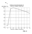
- Fig. 6 is a graph illustrating correlation of contact determinations according to an embodiment of the invention with a reference method.
- aspects of the present invention may be embodied in software programming code, which is typically maintained in permanent storage, such as a computer readable medium.
- software programming code may be stored on a client or a server.
- the software programming code may be embodied on any of a variety of known non-transitory media for use with a data processing system, such as a diskette, hard drive, electronic media or CD-ROM.
- the code may be distributed on such media, or may be distributed to users from the memory or storage of one computer system over a network of some type to storage devices on other computer systems for use by users of such other systems.
- Fig. 1 is a pictorial illustration of a system 10 for performing diagnostic and therapeutic procedures on a heart 12 of a living subject, which is constructed and operative in accordance with a disclosed embodiment of the invention.
- the system comprises a catheter 14, which is percutaneously inserted by an operator 16 through the patient's vascular system into a chamber or vascular structure of the heart 12.
- the operator 16 who is typically a physician, brings the catheter's distal tip 18 into contact with the heart wall at an ablation target site.
- electrical activation maps may then be prepared, according to the methods disclosed in U.S. Patent Nos. 6,226,542 , and 6,301,496 , and in commonly assigned U.S. Patent No.
- Areas determined to be abnormal can be ablated by application of thermal energy, e.g., by passage of radiofrequency electrical current through wires in the catheter to one or more electrodes at the distal tip 18, which apply the radiofrequency energy to the myocardium.
- the energy is absorbed in the tissue, heating it to a point (typically about 50°C) at which it permanently loses its electrical excitability.
- this procedure creates non-conducting lesions in the cardiac tissue, which disrupt the abnormal electrical pathway causing the arrhythmia.
- the principles of the invention can be applied to different heart chambers to treat many different cardiac arrhythmias.
- the catheter 14 typically comprises a handle 20, having suitable controls on the handle to enable the operator 16 to steer, position and orient the distal end of the catheter as desired for the ablation.
- the distal portion of the catheter 14 contains position sensors (not shown) that provide signals to a positioning processor 22, located in a console 24.
- Ablation energy and electrical signals can be conveyed to and from the heart 12 through one or more ablation electrodes 32 located at or near the distal tip 18 via cable 34 to the console 24. Pacing signals and other control signals may be conveyed from the console 24 through the cable 34 and the electrodes 32 to the heart 12. Sensing electrodes 33, also connected to the console 24, are disposed between the ablation electrodes 32 and have connections to the cable 34.
- Wire connections 35 link the console 24 with body surface electrodes 30 and other components of a positioning sub-system.
- the electrodes 32 and the body surface electrodes 30 may be used to measure tissue impedance at the ablation site as taught in U.S. Patent No. 7,536,218, issued to Govari et al. , which is herein incorporated by reference.
- a temperature sensor (not shown), typically a thermocouple or thermistor, may be mounted on or near each of the electrodes 32.
- the console 24 typically contains one or more ablation power generators 25.
- the catheter 14 may be adapted to conduct ablative energy to the heart using any known ablation technique, e.g., radiofrequency energy, ultrasound energy, and laser-produced light energy. Such methods are disclosed in commonly assigned U.S. Patent Nos. 6,814,733 , 6,997,924, and 7,156,816 , which are herein incorporated by reference.
- the positioning processor 22 is an element of a positioning subsystem in the system 10 that measures location and orientation coordinates of the catheter 14.
- the positioning subsystem comprises a magnetic position tracking arrangement that determines the position and orientation of the catheter 14 by generating magnetic fields in a predefined working volume and sensing these fields at the catheter, using field generating coils 28.
- the positioning subsystem may employ impedance measurement, as taught, for example in U.S. Patent No. 7,756,576 , which is hereby incorporated by reference, and in the above-noted U.S. Patent No. 7,536,218 .
- the catheter 14 is coupled to the console 24, which enables the operator 16 to observe and regulate the functions of the catheter 14.
- Console 24 includes a processor, preferably a computer with appropriate signal processing circuits.
- the processor is coupled to drive a monitor 29.
- the signal processing circuits typically receive, amplify, filter and digitize signals from the catheter 14, including signals generated by the above-noted sensors and a plurality of location sensing electrodes (not shown) located distally in the catheter 14.
- the digitized signals are received and used by the console 24 and the positioning system to compute the position and orientation of the catheter 14 and to analyze the electrical signals from the electrodes.
- the system 10 includes other elements, which are not shown in the figures for the sake of simplicity.
- the system 10 may include an electrocardiogram (ECG) monitor, coupled to receive signals from one or more body surface electrodes, so as to provide an ECG synchronization signal to the console 24.
- ECG electrocardiogram
- the system 10 typically also includes a reference position sensor, either on an externally-applied reference patch attached to the exterior of the subject's body, or on an internally-placed catheter, which is inserted into the heart 12 maintained in a fixed position relative to the heart 12. Conventional pumps and lines for circulating liquids through the catheter 14 for cooling the ablation site are provided.
- Fig. 2 is a composite drawing illustrating phase relationships of currents passing through the body surface electrodes 30 and an electrode of the catheter 14 as it moves or is moved into contact with wall 37 of heart 12 ( Fig. 1 ) in accordance with an embodiment of the invention.
- a reference electrode 39 is optionally provided for this purpose.
- the reference electrode 39 does not contact the wall 37.
- the electrodes are driven with a signal at a known frequency, which passes through the tissue and is received by the body surface electrodes 30 ( Fig. 1 ) or some other receiving electrode. Waveforms at the right side of Fig.
- phase relationships include, from top to bottom, a reference waveform 41 taken from the reference electrode 39, a pre-contact waveform 43 from the ablation electrode 32, taken when the ablation electrode 32 is out of contact with the wall 37, and a contact waveform 45, taken when the ablation electrode 32 is in mechanical contact with the wall 37. Further details regarding the significance of such phase relationships are described in commonly assigned copending Application Serial No. 13/343,024 , entitled “Contact Assessment Based on Phase Measurement", which is herein incorporated by reference.
- Impedance phase shifts are indicated by displacement of vertical lines 49, 51 drawn through corresponding maxima of the pre-contact waveform 43 and the contact waveform 45.
- the phase shifts occur when the ablation electrode 32 or the sensing electrode 33 ( Fig. 1 ) is brought into contact with the wall 37.
- Phase measurement of this sort can be used not only to verify tissue contact, but also to check the progress of ablation.
- the phase angle of a current passing between the ablation electrode 32 and the tissue can be determined using an nMARQTM catheter, in combination with a multi-channel RF generator and the above-noted CARTO 3 System.
- the phase may be determined by any of the phase determination methods described in the above mentioned U.S. Patent Application Publication Nos. 2008/0288038 and 2008/0275465 , which are herein incorporated by reference.
- FIG. 3 is a composite diagram including a flow chart of a method of determining contact between a catheter electrode and target tissue in accordance with an embodiment of the invention.
- the diagram illustrates a Markov chain, which is a mathematical system that undergoes transitions among a finite or countable number of possible states. It is a random process characterized as memoryless, in which a subsequent state depends only on the current state, and not on the sequence of events or state changes that preceded it. This specific kind of "memorylessness" is called the Markov property.
- a Markov chain is a sequence of random variables X1, X2, X3, having the Markov property, namely that, given the present state, the future and past states are independent.
- the possible values of X i form a countable set S called the state space of the chain.
- S the state space of the chain.
- two states “E" and "A” are shown.
- the probability of being in a state after an event depends on the current state. If the current state is state E than the probability of remaining in state E is 0.3, whereas if the current state is state A, the probability of transitioning to state E is 0.4.
- Determination of a contacting or non-contacting state of a cardiac catheter electrode can be achieved using a Markov state machine having binary states, "1" representing useful contact between an electrode and endocardium, and "0" representing an out-of-contact state, i.e., a state in which there is not useful contact between the electrode and the endocardium.
- useful contact is used for convenience to indicate a sufficiently secure contact between the electrode and the endocardium to accomplish an intended objective, e.g., ablation or mapping.
- the Markov state machine may be defined as follows, wherein:
- P1 Probability of 1 when the last indication was 1.
- P2 Probability of 1 when the last indication was 0.
- P3 Probability of 0 when the last indication was 1.
- P4 Probability of 0 when the last indication was 0.
- P1, P2, P3, P4 can be accomplished using the process described below.
- the process steps are shown in a particular linear sequence in Fig. 3 for clarity of presentation. However, it will be evident that many of them can be performed in parallel, asynchronously, or in different orders.
- a process could alternatively be represented as a number of interrelated states or events, e.g., in a state diagram. Moreover, not all illustrated process steps may be required to implement the process.
- the process involves analysis of multiple impedance phase measurements of an electrical path between the catheter and the body of the subject extending through the target tissue.
- the process described with reference to Fig. 3 is principally concerned with the argument ⁇ , which gives the phase difference between voltage and current.
- the object is to determine which of two possible contact states exists between the catheter electrode and the endocardium: an in-contact state and an out-of-contact state.
- the procedure begins under the assumption that the electrode is out-of-contact, in which case the motion of the heart during the cardiac cycle can be expected to bring the electrode into contact with the endocardium when some of the readings are taken.
- the motion of the heart during the cardiac cycle can be expected to place the electrode into an out-of-contact relationship with the endocardium. In any case it is expected that sometimes during the readings the contact state will fluctuate.
- Fig. 4 is a prospective example of probability distributions of impedance phase measurements taken from a cardiac catheter operating in accordance with an embodiment of the invention.
- Distribution curves 53, 55 correspond to cases when the electrode is in an out-of-contact state and an in-contact state, respectively.
- An optimum binary classifier for the two states is shown as a broken vertical line 57, corresponding to an impedance phase of 135 degrees.
- impedance readings are typically taken at 200 ms intervals, Any of the above-noted methods for impedance determination may be used.
- a new impedance reading is obtained, and stored in a cyclic buffer.
- the power requirement for obtaining phase angle readings is a less than 10 milliwatts if the ablator is idle. If the ablator is active then 5 - 50 watts is required.
- step 61 it is determined if the cyclic buffer is full. Typically, 100 readings are stored. If the determination is negative, then control returns to initial step 59. It is generally unnecessary for the operator to adjust the catheter while the buffer is being filled.
- step 63 a template for constructing a histogram of the impedance data is prepared, adaptively to the phases that were measured.
- the buffer is scanned and extreme high and low phase values are identified to define limits of a working range of phase angles.
- the range is then subdivided into bins for the histogram. Twelve bins are suitable, but other values may be used if different granularity is desired.
- the values in the buffer are then assigned to the bins to build the histogram. If desired the histogram may be displayed graphically.
- step 65 the number of readings in respective bins are evaluated in order to filter noise by eliminating from further consideration those bins having fewer readings than a predetermined noise threshold. Then, at step 67 the remaining bins are scanned to identify the two bins having the maximum number ( MaxBin ) and minimum number ( MinBin ) of data points. Alternatively, steps 65, 67 may be combined by simply subtracting the noise threshold when determining the maximum and minimum numbers of data points in the bins.
- step 69 it is determined if there is a significant difference between the number of data points in the two bins that were identified in step 67. This may be done using the inequality Abs ⁇ MaxBin - MinBin > Noise , where Noise is the noise threshold.
- decision step 69 can be performed by measuring the variance of the distribution of the current set of readings. If the variance is low, typically 2.5 degrees or less, then it may be inferred that the contact state did not change during the set of readings, and the information provided by current set is inconclusive.
- FIG. 5 shows two state diagrams, which are helpful in understanding principles on which an embodiment of the invention is based.
- An upper diagram 71 illustrates the possibility that the contact state is out-of-contact and unchanging. There is no probability of a transition to an in-contact state. As shown in a lower diagram 73. In a case when the contact state changes as expected, the variance of the impedance readings will be relatively greater, and the corresponding state machine has transitions with exemplary probabilities as shown.
- step 69 If the determination at decision step 69 is affirmative, then control proceeds to step 77.
- the value of the classifier T is adaptive to the current set of impedance readings.
- the value of the classifier T is expected to vary among different subjects, and event some extent in different locations within the heart of a particular subject. Therefore, in order to assure that the binary classifier remains accurately defined, the method may be repeated from time to time as the operator moves the catheter to different locations in the heart.
- the classifier T is compared to the phase angle of a test reading in order to determine if a contact state change has occurred, subject to one or more hysteresis factors. Values of 1.5 degrees for the hysteresis factors are typical. Values of 10% of the dynamic range defined by the extreme values are suitable. However, particularly in the case of catheters were significant amounts of force can be focally applied, the hysteresis factors described below may differ.
- the best test reading is the last reading, i.e., the most recent reading taken in the current set of readings.
- one of the other readings may be chosen as the test reading, for example by random selection or otherwise.
- step 79 it is determined if the electrode is in contact with the endocardium. In the first iteration of the method, the contact state may be assumed. Otherwise the contact state is known from a previous iteration of the method.
- TV the test value
- T the classifier that was calculated in step 77
- HF1 is a hysteresis factor.
- control proceeds to final step 83.
- a state transition has occurred from an in-contact state to an out-of-contact state. An out-of-contact state is reported.
- control proceeds to final step 85. It is concluded that no contact state transition has occurred. The electrode remains in contact with the endocardium. An in-contact state is reported.
- the hysteresis factor HF2 is typically identical to the hysteresis factor HF1 , but this is not necessarily the case.
- control proceeds to final step 83.
- the electrode remains out of contact with the endocardium. An out-of-contact state is reported.
- Listing 1 presents a computer program in pseudocode for carrying out the method described above.
- Table 1 illustrates a numerical example that illustrates the underlying principal of the process of Fig. 3 .
- Table 1 Phase Reading 120 120 100 140 120 110 130 120 120 Indication No Contact No Contact No Contact Contact Contact No Contact Contact Contact Contact
- Fig. 6 is a graph 89 illustrating correlation of contact determinations using the method described with reference to Fig. 3 with measurements using a conventional contact force catheter with the CARTO 3 System as a reference method.
- ThermoCool ® SmartTouchTM Contact Force Sensing Catheter available from Biosense Webster, Inc., is suitable.
- contact force threshold is plotted against accuracy.
- a contact force threshold of 6 is associated with the highest accuracy of the inventive method.
Applications Claiming Priority (1)
| Application Number | Priority Date | Filing Date | Title |
|---|---|---|---|
| US13/589,347 US9168004B2 (en) | 2012-08-20 | 2012-08-20 | Machine learning in determining catheter electrode contact |
Publications (2)
| Publication Number | Publication Date |
|---|---|
| EP2700373A1 true EP2700373A1 (de) | 2014-02-26 |
| EP2700373B1 EP2700373B1 (de) | 2018-02-21 |
Family
ID=49033829
Family Applications (1)
| Application Number | Title | Priority Date | Filing Date |
|---|---|---|---|
| EP13180877.6A Active EP2700373B1 (de) | 2012-08-20 | 2013-08-19 | Maschinenlernen beim bei der Bestimmung des Katheterelektrodenkontakts |
Country Status (7)
| Country | Link |
|---|---|
| US (2) | US9168004B2 (de) |
| EP (1) | EP2700373B1 (de) |
| JP (1) | JP6246525B2 (de) |
| CN (1) | CN103622745B (de) |
| AU (1) | AU2013216586B2 (de) |
| CA (1) | CA2824117A1 (de) |
| IL (1) | IL227874A (de) |
Cited By (5)
| Publication number | Priority date | Publication date | Assignee | Title |
|---|---|---|---|---|
| US10350423B2 (en) | 2016-02-04 | 2019-07-16 | Cardiac Pacemakers, Inc. | Delivery system with force sensor for leadless cardiac device |
| EP3750500A1 (de) * | 2015-03-25 | 2020-12-16 | EPiX Therapeutics, Inc. | Kontakterfassungssysteme und -verfahren |
| EP4014847A1 (de) * | 2020-12-16 | 2022-06-22 | Biosense Webster (Israel) Ltd | Genaue gewebenähe |
| EP4079243A1 (de) * | 2021-04-23 | 2022-10-26 | Koninklijke Philips N.V. | Abtastung für einen katheter |
| US11576714B2 (en) | 2015-03-25 | 2023-02-14 | Epix Therapeutics, Inc. | Contact sensing systems and methods |
Families Citing this family (62)
| Publication number | Priority date | Publication date | Assignee | Title |
|---|---|---|---|---|
| US11389232B2 (en) | 2006-06-28 | 2022-07-19 | Kardium Inc. | Apparatus and method for intra-cardiac mapping and ablation |
| US9119633B2 (en) | 2006-06-28 | 2015-09-01 | Kardium Inc. | Apparatus and method for intra-cardiac mapping and ablation |
| US8906011B2 (en) | 2007-11-16 | 2014-12-09 | Kardium Inc. | Medical device for use in bodily lumens, for example an atrium |
| WO2010093603A1 (en) | 2009-02-11 | 2010-08-19 | Boston Scientific Scimed, Inc. | Insulated ablation catheter devices and methods of use |
| US9693832B2 (en) | 2012-05-21 | 2017-07-04 | Kardium Inc. | Systems and methods for selecting, activating, or selecting and activating transducers |
| US10827977B2 (en) | 2012-05-21 | 2020-11-10 | Kardium Inc. | Systems and methods for activating transducers |
| US9198592B2 (en) | 2012-05-21 | 2015-12-01 | Kardium Inc. | Systems and methods for activating transducers |
| JP6301926B2 (ja) | 2012-08-09 | 2018-03-28 | ユニバーシティ オブ アイオワ リサーチ ファウンデーション | カテーテル、カテーテルシステム、及び組織構造を刺通する方法 |
| US9168004B2 (en) * | 2012-08-20 | 2015-10-27 | Biosense Webster (Israel) Ltd. | Machine learning in determining catheter electrode contact |
| US9427167B2 (en) | 2012-12-20 | 2016-08-30 | Boston Scientific Scimed, Inc. | Real-time feedback for electrode contact during mapping |
| EP3091921B1 (de) | 2014-01-06 | 2019-06-19 | Farapulse, Inc. | Vorrichtung für nierendenervierungsablation |
| WO2015171921A2 (en) | 2014-05-07 | 2015-11-12 | Mickelson Steven R | Methods and apparatus for selective tissue ablation |
| EP3154464A4 (de) | 2014-06-12 | 2018-01-24 | Iowa Approach Inc. | Verfahren und vorrichtung zur schnellen und selektiven gewebeablation mit kühlung |
| WO2015192027A1 (en) | 2014-06-12 | 2015-12-17 | Iowa Approach Inc. | Method and apparatus for rapid and selective transurethral tissue ablation |
| KR102033759B1 (ko) * | 2014-09-23 | 2019-10-17 | 주식회사 한독칼로스메디칼 | 카테터 및 그 제조 방법 |
| SG10201902552QA (en) * | 2014-09-23 | 2019-04-29 | Handok Kalos Medical Inc | Catheter and manufacturing method therefor |
| CN106793968A (zh) | 2014-10-13 | 2017-05-31 | 波士顿科学医学有限公司 | 使用微电极的组织诊断和治疗 |
| WO2016060983A1 (en) | 2014-10-14 | 2016-04-21 | Iowa Approach Inc. | Method and apparatus for rapid and safe pulmonary vein cardiac ablation |
| WO2016065337A1 (en) | 2014-10-24 | 2016-04-28 | Boston Scientific Scimed Inc. | Medical devices with a flexible electrode assembly coupled to an ablation tip |
| US10402086B2 (en) * | 2014-11-14 | 2019-09-03 | Lg Electronics Inc. | Mobile terminal and method for controlling the same |
| US10722184B2 (en) | 2014-11-17 | 2020-07-28 | Kardium Inc. | Systems and methods for selecting, activating, or selecting and activating transducers |
| US10368936B2 (en) | 2014-11-17 | 2019-08-06 | Kardium Inc. | Systems and methods for selecting, activating, or selecting and activating transducers |
| EP3220844B1 (de) | 2014-11-19 | 2020-11-11 | EPiX Therapeutics, Inc. | Systeme für hochauflösende gewebekartierung |
| EP3220841B1 (de) | 2014-11-19 | 2023-01-25 | EPiX Therapeutics, Inc. | Hochauflösende abbildung von gewebe mit schrittmachertherapie |
| EP3220843B1 (de) | 2014-11-19 | 2020-01-01 | EPiX Therapeutics, Inc. | Ablationsvorrichtungen und verfahren zur verwendung einer hochauflösenden elektrodenanordnung |
| US20160143686A1 (en) * | 2014-11-19 | 2016-05-26 | Stereotaxis, Inc. | Inter-electrode impedance for detecting tissue distance, orientation, contact and contact quality |
| US9498628B2 (en) * | 2014-11-21 | 2016-11-22 | Medtronic, Inc. | Electrode selection for electrical stimulation therapy |
| US9743854B2 (en) | 2014-12-18 | 2017-08-29 | Boston Scientific Scimed, Inc. | Real-time morphology analysis for lesion assessment |
| US10143399B2 (en) * | 2015-04-02 | 2018-12-04 | Medtronic Ablation Frontiers Llc | Tissue contact sensing with a multi electrode ablation catheter |
| US10182742B2 (en) * | 2015-04-02 | 2019-01-22 | Medtronic Ablation Frontiers Llc | Tissue contact sensing with a multi electrode ablation catheter |
| US10327859B2 (en) | 2015-09-21 | 2019-06-25 | Biosense Webster (Israel) Ltd. | Catheter stability indication |
| US10130423B1 (en) | 2017-07-06 | 2018-11-20 | Farapulse, Inc. | Systems, devices, and methods for focal ablation |
| US10660702B2 (en) | 2016-01-05 | 2020-05-26 | Farapulse, Inc. | Systems, devices, and methods for focal ablation |
| US10172673B2 (en) | 2016-01-05 | 2019-01-08 | Farapulse, Inc. | Systems devices, and methods for delivery of pulsed electric field ablative energy to endocardial tissue |
| US20170189097A1 (en) | 2016-01-05 | 2017-07-06 | Iowa Approach Inc. | Systems, apparatuses and methods for delivery of ablative energy to tissue |
| EP3429462B1 (de) | 2016-03-15 | 2022-08-03 | EPiX Therapeutics, Inc. | Verbesserte vorrichtungen und systeme zur gespülten ablation |
| US10531917B2 (en) * | 2016-04-15 | 2020-01-14 | Neuwave Medical, Inc. | Systems and methods for energy delivery |
| WO2017218734A1 (en) | 2016-06-16 | 2017-12-21 | Iowa Approach, Inc. | Systems, apparatuses, and methods for guide wire delivery |
| US10403053B2 (en) * | 2016-11-15 | 2019-09-03 | Biosense Webster (Israel) Ltd. | Marking sparse areas on maps |
| WO2018092071A1 (en) * | 2016-11-16 | 2018-05-24 | Navix International Limited | Estimators for ablation effectiveness |
| CN110809448B (zh) | 2017-04-27 | 2022-11-25 | Epix疗法公司 | 确定导管尖端与组织之间接触的性质 |
| US9987081B1 (en) | 2017-04-27 | 2018-06-05 | Iowa Approach, Inc. | Systems, devices, and methods for signal generation |
| US10617867B2 (en) | 2017-04-28 | 2020-04-14 | Farapulse, Inc. | Systems, devices, and methods for delivery of pulsed electric field ablative energy to esophageal tissue |
| CN115844523A (zh) | 2017-09-12 | 2023-03-28 | 波士顿科学医学有限公司 | 用于心室局灶性消融的系统、设备和方法 |
| CN112087978B (zh) | 2018-05-07 | 2023-01-17 | 波士顿科学医学有限公司 | 心外膜消融导管 |
| WO2019217317A1 (en) | 2018-05-07 | 2019-11-14 | Farapulse, Inc. | Systems, apparatuses, and methods for filtering high voltage noise induced by pulsed electric field ablation |
| CN115836908A (zh) | 2018-05-07 | 2023-03-24 | 波士顿科学医学有限公司 | 用于将消融能量递送到组织的系统、设备和方法 |
| US10687892B2 (en) | 2018-09-20 | 2020-06-23 | Farapulse, Inc. | Systems, apparatuses, and methods for delivery of pulsed electric field ablative energy to endocardial tissue |
| CN111345909B (zh) * | 2018-12-20 | 2021-11-02 | 四川锦江电子科技有限公司 | 一种用于确定磁电映射关系的方法和装置 |
| US11826088B2 (en) | 2018-12-28 | 2023-11-28 | Biosense Webster (Israel) Ltd. | Adjusting phases of multiphase ablation generator to detect contact |
| US11426126B2 (en) | 2019-05-23 | 2022-08-30 | Biosense Webster (Israel) Ltd. | Indicating electrode contact |
| US20210077180A1 (en) | 2019-09-12 | 2021-03-18 | Biosense Webster (Israel) Ltd. | Balloon Catheter with Force Sensor |
| US10625080B1 (en) | 2019-09-17 | 2020-04-21 | Farapulse, Inc. | Systems, apparatuses, and methods for detecting ectopic electrocardiogram signals during pulsed electric field ablation |
| US11065047B2 (en) | 2019-11-20 | 2021-07-20 | Farapulse, Inc. | Systems, apparatuses, and methods for protecting electronic components from high power noise induced by high voltage pulses |
| US11497541B2 (en) | 2019-11-20 | 2022-11-15 | Boston Scientific Scimed, Inc. | Systems, apparatuses, and methods for protecting electronic components from high power noise induced by high voltage pulses |
| US10842572B1 (en) | 2019-11-25 | 2020-11-24 | Farapulse, Inc. | Methods, systems, and apparatuses for tracking ablation devices and generating lesion lines |
| US11872026B2 (en) | 2019-12-04 | 2024-01-16 | Biosense Webster (Israel) Ltd. | Catheter contact force sensor |
| CN116529009A (zh) | 2020-11-30 | 2023-08-01 | Osg株式会社 | 立铣刀 |
| US11918383B2 (en) | 2020-12-21 | 2024-03-05 | Biosense Webster (Israel) Ltd. | Visualizing performance of catheter electrodes |
| US11864844B2 (en) | 2020-12-22 | 2024-01-09 | Biosense Webster (Israel) Ltd. | Distal end assembly guidance |
| US20230157569A1 (en) | 2021-11-22 | 2023-05-25 | Biosense Webster (Israel) Ltd. | Mapping System with Real Time Electrogram Overlay |
| US20230210437A1 (en) | 2021-12-30 | 2023-07-06 | Biosense Webster (Israel) Ltd. | Intuitive Mapping System |
Citations (17)
| Publication number | Priority date | Publication date | Assignee | Title |
|---|---|---|---|---|
| US6226542B1 (en) | 1998-07-24 | 2001-05-01 | Biosense, Inc. | Three-dimensional reconstruction of intrabody organs |
| US6241724B1 (en) | 1993-10-19 | 2001-06-05 | Ep Technologies, Inc. | Systems and methods for creating lesions in body tissue using segmented electrode assemblies |
| US6301496B1 (en) | 1998-07-24 | 2001-10-09 | Biosense, Inc. | Vector mapping of three-dimensionally reconstructed intrabody organs and method of display |
| US6391024B1 (en) * | 1999-06-17 | 2002-05-21 | Cardiac Pacemakers, Inc. | RF ablation apparatus and method having electrode/tissue contact assessment scheme and electrocardiogram filtering |
| US6695808B2 (en) | 2000-03-23 | 2004-02-24 | Scimed Life Systems, Inc. | Pressure sensor for therapeutic delivery device and method |
| US6814733B2 (en) | 2002-01-31 | 2004-11-09 | Biosense, Inc. | Radio frequency pulmonary vein isolation |
| US6892091B1 (en) | 2000-02-18 | 2005-05-10 | Biosense, Inc. | Catheter, method and apparatus for generating an electrical map of a chamber of the heart |
| US6915149B2 (en) | 1996-01-08 | 2005-07-05 | Biosense, Inc. | Method of pacing a heart using implantable device |
| US6997924B2 (en) | 2002-09-17 | 2006-02-14 | Biosense Inc. | Laser pulmonary vein isolation |
| US7156816B2 (en) | 2002-11-26 | 2007-01-02 | Biosense, Inc. | Ultrasound pulmonary vein isolation |
| US20070100332A1 (en) | 2005-10-27 | 2007-05-03 | St. Jude Medical, Atrial Fibrillation Division, Inc. | Systems and methods for electrode contact assessment |
| US7306593B2 (en) | 2002-10-21 | 2007-12-11 | Biosense, Inc. | Prediction and assessment of ablation of cardiac tissue |
| US20080275465A1 (en) | 2005-12-06 | 2008-11-06 | Saurav Paul | Design of Handle Set for Ablation Catheter with Indicators of Catheter and Tissue Parameters |
| US20080312521A1 (en) * | 2007-06-14 | 2008-12-18 | Solomon Edward G | System and method for determining electrode-tissue contact using phase difference |
| US7536218B2 (en) | 2005-07-15 | 2009-05-19 | Biosense Webster, Inc. | Hybrid magnetic-based and impedance-based position sensing |
| US7756576B2 (en) | 2005-08-26 | 2010-07-13 | Biosense Webster, Inc. | Position sensing and detection of skin impedance |
| US20130172875A1 (en) * | 2012-01-04 | 2013-07-04 | Assaf Govari | Contact assessment based on phase measurement |
Family Cites Families (4)
| Publication number | Priority date | Publication date | Assignee | Title |
|---|---|---|---|---|
| CA2612679A1 (en) * | 2005-06-20 | 2007-01-04 | Richardo D. Roman | Ablation catheter |
| CN101190146B (zh) * | 2006-11-21 | 2010-12-08 | 李楚森 | 一种心脏介入消融导管 |
| US8160690B2 (en) * | 2007-06-14 | 2012-04-17 | Hansen Medical, Inc. | System and method for determining electrode-tissue contact based on amplitude modulation of sensed signal |
| US9168004B2 (en) * | 2012-08-20 | 2015-10-27 | Biosense Webster (Israel) Ltd. | Machine learning in determining catheter electrode contact |
-
2012
- 2012-08-20 US US13/589,347 patent/US9168004B2/en active Active
-
2013
- 2013-08-08 IL IL227874A patent/IL227874A/en active IP Right Grant
- 2013-08-13 AU AU2013216586A patent/AU2013216586B2/en active Active
- 2013-08-19 CA CA2824117A patent/CA2824117A1/en not_active Abandoned
- 2013-08-19 EP EP13180877.6A patent/EP2700373B1/de active Active
- 2013-08-19 JP JP2013169484A patent/JP6246525B2/ja active Active
- 2013-08-20 CN CN201310364424.1A patent/CN103622745B/zh active Active
-
2015
- 2015-09-22 US US14/860,894 patent/US9433465B2/en active Active
Patent Citations (18)
| Publication number | Priority date | Publication date | Assignee | Title |
|---|---|---|---|---|
| US6241724B1 (en) | 1993-10-19 | 2001-06-05 | Ep Technologies, Inc. | Systems and methods for creating lesions in body tissue using segmented electrode assemblies |
| US6915149B2 (en) | 1996-01-08 | 2005-07-05 | Biosense, Inc. | Method of pacing a heart using implantable device |
| US6226542B1 (en) | 1998-07-24 | 2001-05-01 | Biosense, Inc. | Three-dimensional reconstruction of intrabody organs |
| US6301496B1 (en) | 1998-07-24 | 2001-10-09 | Biosense, Inc. | Vector mapping of three-dimensionally reconstructed intrabody organs and method of display |
| US6391024B1 (en) * | 1999-06-17 | 2002-05-21 | Cardiac Pacemakers, Inc. | RF ablation apparatus and method having electrode/tissue contact assessment scheme and electrocardiogram filtering |
| US6892091B1 (en) | 2000-02-18 | 2005-05-10 | Biosense, Inc. | Catheter, method and apparatus for generating an electrical map of a chamber of the heart |
| US6695808B2 (en) | 2000-03-23 | 2004-02-24 | Scimed Life Systems, Inc. | Pressure sensor for therapeutic delivery device and method |
| US6814733B2 (en) | 2002-01-31 | 2004-11-09 | Biosense, Inc. | Radio frequency pulmonary vein isolation |
| US6997924B2 (en) | 2002-09-17 | 2006-02-14 | Biosense Inc. | Laser pulmonary vein isolation |
| US7306593B2 (en) | 2002-10-21 | 2007-12-11 | Biosense, Inc. | Prediction and assessment of ablation of cardiac tissue |
| US7156816B2 (en) | 2002-11-26 | 2007-01-02 | Biosense, Inc. | Ultrasound pulmonary vein isolation |
| US7536218B2 (en) | 2005-07-15 | 2009-05-19 | Biosense Webster, Inc. | Hybrid magnetic-based and impedance-based position sensing |
| US7756576B2 (en) | 2005-08-26 | 2010-07-13 | Biosense Webster, Inc. | Position sensing and detection of skin impedance |
| US20070100332A1 (en) | 2005-10-27 | 2007-05-03 | St. Jude Medical, Atrial Fibrillation Division, Inc. | Systems and methods for electrode contact assessment |
| US20080275465A1 (en) | 2005-12-06 | 2008-11-06 | Saurav Paul | Design of Handle Set for Ablation Catheter with Indicators of Catheter and Tissue Parameters |
| US20080288038A1 (en) | 2005-12-06 | 2008-11-20 | Saurav Paul | Method for Displaying Catheter Electrode-Tissue Contact in Electro-Anatomic Mapping and Navigation System |
| US20080312521A1 (en) * | 2007-06-14 | 2008-12-18 | Solomon Edward G | System and method for determining electrode-tissue contact using phase difference |
| US20130172875A1 (en) * | 2012-01-04 | 2013-07-04 | Assaf Govari | Contact assessment based on phase measurement |
Cited By (6)
| Publication number | Priority date | Publication date | Assignee | Title |
|---|---|---|---|---|
| EP3750500A1 (de) * | 2015-03-25 | 2020-12-16 | EPiX Therapeutics, Inc. | Kontakterfassungssysteme und -verfahren |
| US11576714B2 (en) | 2015-03-25 | 2023-02-14 | Epix Therapeutics, Inc. | Contact sensing systems and methods |
| US10350423B2 (en) | 2016-02-04 | 2019-07-16 | Cardiac Pacemakers, Inc. | Delivery system with force sensor for leadless cardiac device |
| EP4014847A1 (de) * | 2020-12-16 | 2022-06-22 | Biosense Webster (Israel) Ltd | Genaue gewebenähe |
| EP4079243A1 (de) * | 2021-04-23 | 2022-10-26 | Koninklijke Philips N.V. | Abtastung für einen katheter |
| WO2022223417A1 (en) * | 2021-04-23 | 2022-10-27 | Koninklijke Philips N.V. | Sensing for a catheter |
Also Published As
| Publication number | Publication date |
|---|---|
| US9168004B2 (en) | 2015-10-27 |
| US20160008065A1 (en) | 2016-01-14 |
| US20140051959A1 (en) | 2014-02-20 |
| JP2014036861A (ja) | 2014-02-27 |
| CN103622745A (zh) | 2014-03-12 |
| US9433465B2 (en) | 2016-09-06 |
| JP6246525B2 (ja) | 2017-12-13 |
| AU2013216586A1 (en) | 2014-03-06 |
| EP2700373B1 (de) | 2018-02-21 |
| IL227874A (en) | 2017-01-31 |
| AU2013216586B2 (en) | 2017-09-14 |
| CN103622745B (zh) | 2017-05-17 |
| CA2824117A1 (en) | 2014-02-20 |
Similar Documents
| Publication | Publication Date | Title |
|---|---|---|
| US9433465B2 (en) | Machine learning in determining catheter electrode contact | |
| EP2612612B1 (de) | Kontaktüberprüfung basierend auf Phasenmessung | |
| JP6510119B2 (ja) | 接触力に基づくアブレーション電力制御 | |
| US10610288B2 (en) | Device and method for real-time lesion estimation during ablation | |
| US8406866B2 (en) | System and method for assessing coupling between an electrode and tissue | |
| CN104414653B (zh) | 确定导管不存在接触 | |
| CN111973272A (zh) | 指示电极接触 | |
| CN113925597A (zh) | 基于所测量的双极信号的幅度来估计不可逆电穿孔消融的进展 | |
| CN116138874A (zh) | 具有实时电描记图叠加的标测系统 | |
| EP3888552A1 (de) | Schrittmacherinduzierte elektrische aktivierungsgradierung | |
| US20220183748A1 (en) | Accurate tissue proximity | |
| CN116407260A (zh) | 直观标测系统 |
Legal Events
| Date | Code | Title | Description |
|---|---|---|---|
| PUAI | Public reference made under article 153(3) epc to a published international application that has entered the european phase |
Free format text: ORIGINAL CODE: 0009012 |
|
| AK | Designated contracting states |
Kind code of ref document: A1 Designated state(s): AL AT BE BG CH CY CZ DE DK EE ES FI FR GB GR HR HU IE IS IT LI LT LU LV MC MK MT NL NO PL PT RO RS SE SI SK SM TR |
|
| AX | Request for extension of the european patent |
Extension state: BA ME |
|
| 17P | Request for examination filed |
Effective date: 20140826 |
|
| RBV | Designated contracting states (corrected) |
Designated state(s): AL AT BE BG CH CY CZ DE DK EE ES FI FR GB GR HR HU IE IS IT LI LT LU LV MC MK MT NL NO PL PT RO RS SE SI SK SM TR |
|
| RIC1 | Information provided on ipc code assigned before grant |
Ipc: A61B 18/12 20060101AFI20170914BHEP Ipc: A61B 5/053 20060101ALI20170914BHEP Ipc: A61B 5/00 20060101ALI20170914BHEP Ipc: A61B 18/00 20060101ALN20170914BHEP Ipc: A61B 18/14 20060101ALN20170914BHEP Ipc: A61B 17/00 20060101ALN20170914BHEP |
|
| GRAP | Despatch of communication of intention to grant a patent |
Free format text: ORIGINAL CODE: EPIDOSNIGR1 |
|
| INTG | Intention to grant announced |
Effective date: 20171031 |
|
| GRAS | Grant fee paid |
Free format text: ORIGINAL CODE: EPIDOSNIGR3 |
|
| GRAA | (expected) grant |
Free format text: ORIGINAL CODE: 0009210 |
|
| RAP1 | Party data changed (applicant data changed or rights of an application transferred) |
Owner name: BIOSENSE WEBSTER (ISRAEL) LTD. |
|
| AK | Designated contracting states |
Kind code of ref document: B1 Designated state(s): AL AT BE BG CH CY CZ DE DK EE ES FI FR GB GR HR HU IE IS IT LI LT LU LV MC MK MT NL NO PL PT RO RS SE SI SK SM TR |
|
| REG | Reference to a national code |
Ref country code: GB Ref legal event code: FG4D |
|
| REG | Reference to a national code |
Ref country code: CH Ref legal event code: EP |
|
| REG | Reference to a national code |
Ref country code: AT Ref legal event code: REF Ref document number: 970846 Country of ref document: AT Kind code of ref document: T Effective date: 20180315 |
|
| REG | Reference to a national code |
Ref country code: IE Ref legal event code: FG4D |
|
| REG | Reference to a national code |
Ref country code: DE Ref legal event code: R096 Ref document number: 602013033266 Country of ref document: DE |
|
| REG | Reference to a national code |
Ref country code: NL Ref legal event code: FP |
|
| REG | Reference to a national code |
Ref country code: LT Ref legal event code: MG4D |
|
| REG | Reference to a national code |
Ref country code: FR Ref legal event code: PLFP Year of fee payment: 6 |
|
| REG | Reference to a national code |
Ref country code: AT Ref legal event code: MK05 Ref document number: 970846 Country of ref document: AT Kind code of ref document: T Effective date: 20180221 |
|
| PG25 | Lapsed in a contracting state [announced via postgrant information from national office to epo] |
Ref country code: ES Free format text: LAPSE BECAUSE OF FAILURE TO SUBMIT A TRANSLATION OF THE DESCRIPTION OR TO PAY THE FEE WITHIN THE PRESCRIBED TIME-LIMIT Effective date: 20180221 Ref country code: CY Free format text: LAPSE BECAUSE OF FAILURE TO SUBMIT A TRANSLATION OF THE DESCRIPTION OR TO PAY THE FEE WITHIN THE PRESCRIBED TIME-LIMIT Effective date: 20180221 Ref country code: LT Free format text: LAPSE BECAUSE OF FAILURE TO SUBMIT A TRANSLATION OF THE DESCRIPTION OR TO PAY THE FEE WITHIN THE PRESCRIBED TIME-LIMIT Effective date: 20180221 Ref country code: HR Free format text: LAPSE BECAUSE OF FAILURE TO SUBMIT A TRANSLATION OF THE DESCRIPTION OR TO PAY THE FEE WITHIN THE PRESCRIBED TIME-LIMIT Effective date: 20180221 Ref country code: FI Free format text: LAPSE BECAUSE OF FAILURE TO SUBMIT A TRANSLATION OF THE DESCRIPTION OR TO PAY THE FEE WITHIN THE PRESCRIBED TIME-LIMIT Effective date: 20180221 Ref country code: NO Free format text: LAPSE BECAUSE OF FAILURE TO SUBMIT A TRANSLATION OF THE DESCRIPTION OR TO PAY THE FEE WITHIN THE PRESCRIBED TIME-LIMIT Effective date: 20180521 |
|
| PG25 | Lapsed in a contracting state [announced via postgrant information from national office to epo] |
Ref country code: AT Free format text: LAPSE BECAUSE OF FAILURE TO SUBMIT A TRANSLATION OF THE DESCRIPTION OR TO PAY THE FEE WITHIN THE PRESCRIBED TIME-LIMIT Effective date: 20180221 Ref country code: LV Free format text: LAPSE BECAUSE OF FAILURE TO SUBMIT A TRANSLATION OF THE DESCRIPTION OR TO PAY THE FEE WITHIN THE PRESCRIBED TIME-LIMIT Effective date: 20180221 Ref country code: SE Free format text: LAPSE BECAUSE OF FAILURE TO SUBMIT A TRANSLATION OF THE DESCRIPTION OR TO PAY THE FEE WITHIN THE PRESCRIBED TIME-LIMIT Effective date: 20180221 Ref country code: RS Free format text: LAPSE BECAUSE OF FAILURE TO SUBMIT A TRANSLATION OF THE DESCRIPTION OR TO PAY THE FEE WITHIN THE PRESCRIBED TIME-LIMIT Effective date: 20180221 Ref country code: BG Free format text: LAPSE BECAUSE OF FAILURE TO SUBMIT A TRANSLATION OF THE DESCRIPTION OR TO PAY THE FEE WITHIN THE PRESCRIBED TIME-LIMIT Effective date: 20180521 Ref country code: GR Free format text: LAPSE BECAUSE OF FAILURE TO SUBMIT A TRANSLATION OF THE DESCRIPTION OR TO PAY THE FEE WITHIN THE PRESCRIBED TIME-LIMIT Effective date: 20180522 |
|
| PG25 | Lapsed in a contracting state [announced via postgrant information from national office to epo] |
Ref country code: AL Free format text: LAPSE BECAUSE OF FAILURE TO SUBMIT A TRANSLATION OF THE DESCRIPTION OR TO PAY THE FEE WITHIN THE PRESCRIBED TIME-LIMIT Effective date: 20180221 Ref country code: RO Free format text: LAPSE BECAUSE OF FAILURE TO SUBMIT A TRANSLATION OF THE DESCRIPTION OR TO PAY THE FEE WITHIN THE PRESCRIBED TIME-LIMIT Effective date: 20180221 Ref country code: EE Free format text: LAPSE BECAUSE OF FAILURE TO SUBMIT A TRANSLATION OF THE DESCRIPTION OR TO PAY THE FEE WITHIN THE PRESCRIBED TIME-LIMIT Effective date: 20180221 Ref country code: PL Free format text: LAPSE BECAUSE OF FAILURE TO SUBMIT A TRANSLATION OF THE DESCRIPTION OR TO PAY THE FEE WITHIN THE PRESCRIBED TIME-LIMIT Effective date: 20180221 |
|
| REG | Reference to a national code |
Ref country code: DE Ref legal event code: R097 Ref document number: 602013033266 Country of ref document: DE |
|
| PG25 | Lapsed in a contracting state [announced via postgrant information from national office to epo] |
Ref country code: DK Free format text: LAPSE BECAUSE OF FAILURE TO SUBMIT A TRANSLATION OF THE DESCRIPTION OR TO PAY THE FEE WITHIN THE PRESCRIBED TIME-LIMIT Effective date: 20180221 Ref country code: SM Free format text: LAPSE BECAUSE OF FAILURE TO SUBMIT A TRANSLATION OF THE DESCRIPTION OR TO PAY THE FEE WITHIN THE PRESCRIBED TIME-LIMIT Effective date: 20180221 Ref country code: SK Free format text: LAPSE BECAUSE OF FAILURE TO SUBMIT A TRANSLATION OF THE DESCRIPTION OR TO PAY THE FEE WITHIN THE PRESCRIBED TIME-LIMIT Effective date: 20180221 Ref country code: CZ Free format text: LAPSE BECAUSE OF FAILURE TO SUBMIT A TRANSLATION OF THE DESCRIPTION OR TO PAY THE FEE WITHIN THE PRESCRIBED TIME-LIMIT Effective date: 20180221 |
|
| PLBE | No opposition filed within time limit |
Free format text: ORIGINAL CODE: 0009261 |
|
| STAA | Information on the status of an ep patent application or granted ep patent |
Free format text: STATUS: NO OPPOSITION FILED WITHIN TIME LIMIT |
|
| 26N | No opposition filed |
Effective date: 20181122 |
|
| PG25 | Lapsed in a contracting state [announced via postgrant information from national office to epo] |
Ref country code: SI Free format text: LAPSE BECAUSE OF FAILURE TO SUBMIT A TRANSLATION OF THE DESCRIPTION OR TO PAY THE FEE WITHIN THE PRESCRIBED TIME-LIMIT Effective date: 20180221 |
|
| PG25 | Lapsed in a contracting state [announced via postgrant information from national office to epo] |
Ref country code: MC Free format text: LAPSE BECAUSE OF FAILURE TO SUBMIT A TRANSLATION OF THE DESCRIPTION OR TO PAY THE FEE WITHIN THE PRESCRIBED TIME-LIMIT Effective date: 20180221 |
|
| REG | Reference to a national code |
Ref country code: CH Ref legal event code: PL |
|
| PG25 | Lapsed in a contracting state [announced via postgrant information from national office to epo] |
Ref country code: LU Free format text: LAPSE BECAUSE OF NON-PAYMENT OF DUE FEES Effective date: 20180819 Ref country code: CH Free format text: LAPSE BECAUSE OF NON-PAYMENT OF DUE FEES Effective date: 20180831 Ref country code: LI Free format text: LAPSE BECAUSE OF NON-PAYMENT OF DUE FEES Effective date: 20180831 |
|
| REG | Reference to a national code |
Ref country code: IE Ref legal event code: MM4A |
|
| PG25 | Lapsed in a contracting state [announced via postgrant information from national office to epo] |
Ref country code: IE Free format text: LAPSE BECAUSE OF NON-PAYMENT OF DUE FEES Effective date: 20180819 |
|
| PG25 | Lapsed in a contracting state [announced via postgrant information from national office to epo] |
Ref country code: MT Free format text: LAPSE BECAUSE OF NON-PAYMENT OF DUE FEES Effective date: 20180819 |
|
| PG25 | Lapsed in a contracting state [announced via postgrant information from national office to epo] |
Ref country code: TR Free format text: LAPSE BECAUSE OF FAILURE TO SUBMIT A TRANSLATION OF THE DESCRIPTION OR TO PAY THE FEE WITHIN THE PRESCRIBED TIME-LIMIT Effective date: 20180221 |
|
| PG25 | Lapsed in a contracting state [announced via postgrant information from national office to epo] |
Ref country code: PT Free format text: LAPSE BECAUSE OF FAILURE TO SUBMIT A TRANSLATION OF THE DESCRIPTION OR TO PAY THE FEE WITHIN THE PRESCRIBED TIME-LIMIT Effective date: 20180221 Ref country code: HU Free format text: LAPSE BECAUSE OF FAILURE TO SUBMIT A TRANSLATION OF THE DESCRIPTION OR TO PAY THE FEE WITHIN THE PRESCRIBED TIME-LIMIT; INVALID AB INITIO Effective date: 20130819 |
|
| PG25 | Lapsed in a contracting state [announced via postgrant information from national office to epo] |
Ref country code: MK Free format text: LAPSE BECAUSE OF NON-PAYMENT OF DUE FEES Effective date: 20180221 |
|
| PG25 | Lapsed in a contracting state [announced via postgrant information from national office to epo] |
Ref country code: IS Free format text: LAPSE BECAUSE OF FAILURE TO SUBMIT A TRANSLATION OF THE DESCRIPTION OR TO PAY THE FEE WITHIN THE PRESCRIBED TIME-LIMIT Effective date: 20180621 |
|
| PGFP | Annual fee paid to national office [announced via postgrant information from national office to epo] |
Ref country code: NL Payment date: 20230718 Year of fee payment: 11 |
|
| PGFP | Annual fee paid to national office [announced via postgrant information from national office to epo] |
Ref country code: IT Payment date: 20230711 Year of fee payment: 11 Ref country code: GB Payment date: 20230629 Year of fee payment: 11 |
|
| PGFP | Annual fee paid to national office [announced via postgrant information from national office to epo] |
Ref country code: FR Payment date: 20230703 Year of fee payment: 11 Ref country code: DE Payment date: 20230703 Year of fee payment: 11 Ref country code: BE Payment date: 20230719 Year of fee payment: 11 |