EP2698239B1 - Verfahren und Vorrichtung zur Montage und/oder Demontage von Blasformen - Google Patents
Verfahren und Vorrichtung zur Montage und/oder Demontage von Blasformen Download PDFInfo
- Publication number
- EP2698239B1 EP2698239B1 EP13192285.8A EP13192285A EP2698239B1 EP 2698239 B1 EP2698239 B1 EP 2698239B1 EP 13192285 A EP13192285 A EP 13192285A EP 2698239 B1 EP2698239 B1 EP 2698239B1
- Authority
- EP
- European Patent Office
- Prior art keywords
- blow mould
- blow mold
- blow
- carrier
- mold
- Prior art date
- Legal status (The legal status is an assumption and is not a legal conclusion. Google has not performed a legal analysis and makes no representation as to the accuracy of the status listed.)
- Active
Links
- 238000000034 method Methods 0.000 title claims description 27
- 229920003023 plastic Polymers 0.000 claims description 26
- 239000004033 plastic Substances 0.000 claims description 26
- 230000007246 mechanism Effects 0.000 claims description 17
- 238000000926 separation method Methods 0.000 claims description 4
- 238000007493 shaping process Methods 0.000 claims 12
- 239000000463 material Substances 0.000 claims 6
- 238000000071 blow moulding Methods 0.000 description 13
- 239000000969 carrier Substances 0.000 description 11
- 238000007664 blowing Methods 0.000 description 9
- 230000008859 change Effects 0.000 description 6
- 230000008569 process Effects 0.000 description 5
- XLYOFNOQVPJJNP-UHFFFAOYSA-N water Substances O XLYOFNOQVPJJNP-UHFFFAOYSA-N 0.000 description 5
- 238000012546 transfer Methods 0.000 description 4
- 238000004140 cleaning Methods 0.000 description 2
- 230000008878 coupling Effects 0.000 description 2
- 238000010168 coupling process Methods 0.000 description 2
- 238000005859 coupling reaction Methods 0.000 description 2
- 230000001404 mediated effect Effects 0.000 description 2
- 238000003860 storage Methods 0.000 description 2
- 238000013459 approach Methods 0.000 description 1
- 239000003795 chemical substances by application Substances 0.000 description 1
- 238000004891 communication Methods 0.000 description 1
- 239000002826 coolant Substances 0.000 description 1
- 230000001419 dependent effect Effects 0.000 description 1
- 238000011161 development Methods 0.000 description 1
- 230000018109 developmental process Effects 0.000 description 1
- 238000006073 displacement reaction Methods 0.000 description 1
- 238000010438 heat treatment Methods 0.000 description 1
- 238000003780 insertion Methods 0.000 description 1
- 230000037431 insertion Effects 0.000 description 1
- 239000007788 liquid Substances 0.000 description 1
- 238000004519 manufacturing process Methods 0.000 description 1
- 230000001360 synchronised effect Effects 0.000 description 1
Images


Classifications
-
- B—PERFORMING OPERATIONS; TRANSPORTING
- B29—WORKING OF PLASTICS; WORKING OF SUBSTANCES IN A PLASTIC STATE IN GENERAL
- B29C—SHAPING OR JOINING OF PLASTICS; SHAPING OF MATERIAL IN A PLASTIC STATE, NOT OTHERWISE PROVIDED FOR; AFTER-TREATMENT OF THE SHAPED PRODUCTS, e.g. REPAIRING
- B29C49/00—Blow-moulding, i.e. blowing a preform or parison to a desired shape within a mould; Apparatus therefor
- B29C49/42—Component parts, details or accessories; Auxiliary operations
- B29C49/48—Moulds
-
- B—PERFORMING OPERATIONS; TRANSPORTING
- B23—MACHINE TOOLS; METAL-WORKING NOT OTHERWISE PROVIDED FOR
- B23H—WORKING OF METAL BY THE ACTION OF A HIGH CONCENTRATION OF ELECTRIC CURRENT ON A WORKPIECE USING AN ELECTRODE WHICH TAKES THE PLACE OF A TOOL; SUCH WORKING COMBINED WITH OTHER FORMS OF WORKING OF METAL
- B23H7/00—Processes or apparatus applicable to both electrical discharge machining and electrochemical machining
- B23H7/02—Wire-cutting
- B23H7/08—Wire electrodes
-
- C—CHEMISTRY; METALLURGY
- C22—METALLURGY; FERROUS OR NON-FERROUS ALLOYS; TREATMENT OF ALLOYS OR NON-FERROUS METALS
- C22C—ALLOYS
- C22C9/00—Alloys based on copper
- C22C9/04—Alloys based on copper with zinc as the next major constituent
-
- B—PERFORMING OPERATIONS; TRANSPORTING
- B29—WORKING OF PLASTICS; WORKING OF SUBSTANCES IN A PLASTIC STATE IN GENERAL
- B29C—SHAPING OR JOINING OF PLASTICS; SHAPING OF MATERIAL IN A PLASTIC STATE, NOT OTHERWISE PROVIDED FOR; AFTER-TREATMENT OF THE SHAPED PRODUCTS, e.g. REPAIRING
- B29C49/00—Blow-moulding, i.e. blowing a preform or parison to a desired shape within a mould; Apparatus therefor
- B29C49/42—Component parts, details or accessories; Auxiliary operations
- B29C49/48—Moulds
- B29C2049/4856—Mounting, exchanging or centering moulds or parts thereof
- B29C2049/4858—Exchanging mould parts, e.g. for changing the mould size or geometry for making different products in the same mould
-
- B—PERFORMING OPERATIONS; TRANSPORTING
- B29—WORKING OF PLASTICS; WORKING OF SUBSTANCES IN A PLASTIC STATE IN GENERAL
- B29C—SHAPING OR JOINING OF PLASTICS; SHAPING OF MATERIAL IN A PLASTIC STATE, NOT OTHERWISE PROVIDED FOR; AFTER-TREATMENT OF THE SHAPED PRODUCTS, e.g. REPAIRING
- B29C49/00—Blow-moulding, i.e. blowing a preform or parison to a desired shape within a mould; Apparatus therefor
- B29C49/42—Component parts, details or accessories; Auxiliary operations
- B29C49/48—Moulds
- B29C2049/4856—Mounting, exchanging or centering moulds or parts thereof
- B29C2049/4864—Fixed by a special construction to the mould half carriers, e.g. using insulating material between the mould and the mould half carrier
-
- B—PERFORMING OPERATIONS; TRANSPORTING
- B29—WORKING OF PLASTICS; WORKING OF SUBSTANCES IN A PLASTIC STATE IN GENERAL
- B29C—SHAPING OR JOINING OF PLASTICS; SHAPING OF MATERIAL IN A PLASTIC STATE, NOT OTHERWISE PROVIDED FOR; AFTER-TREATMENT OF THE SHAPED PRODUCTS, e.g. REPAIRING
- B29C49/00—Blow-moulding, i.e. blowing a preform or parison to a desired shape within a mould; Apparatus therefor
- B29C49/42—Component parts, details or accessories; Auxiliary operations
- B29C49/48—Moulds
- B29C2049/4879—Moulds characterised by mould configurations
- B29C2049/4889—Mould halves consisting of an independent neck, main and bottom part
-
- B—PERFORMING OPERATIONS; TRANSPORTING
- B29—WORKING OF PLASTICS; WORKING OF SUBSTANCES IN A PLASTIC STATE IN GENERAL
- B29C—SHAPING OR JOINING OF PLASTICS; SHAPING OF MATERIAL IN A PLASTIC STATE, NOT OTHERWISE PROVIDED FOR; AFTER-TREATMENT OF THE SHAPED PRODUCTS, e.g. REPAIRING
- B29C49/00—Blow-moulding, i.e. blowing a preform or parison to a desired shape within a mould; Apparatus therefor
- B29C49/42—Component parts, details or accessories; Auxiliary operations
- B29C49/48—Moulds
- B29C2049/4879—Moulds characterised by mould configurations
- B29C2049/4892—Mould halves consisting of an independent main and bottom part
-
- B—PERFORMING OPERATIONS; TRANSPORTING
- B29—WORKING OF PLASTICS; WORKING OF SUBSTANCES IN A PLASTIC STATE IN GENERAL
- B29C—SHAPING OR JOINING OF PLASTICS; SHAPING OF MATERIAL IN A PLASTIC STATE, NOT OTHERWISE PROVIDED FOR; AFTER-TREATMENT OF THE SHAPED PRODUCTS, e.g. REPAIRING
- B29C2949/00—Indexing scheme relating to blow-moulding
- B29C2949/07—Preforms or parisons characterised by their configuration
- B29C2949/0715—Preforms or parisons characterised by their configuration the preform having one end closed
-
- B—PERFORMING OPERATIONS; TRANSPORTING
- B29—WORKING OF PLASTICS; WORKING OF SUBSTANCES IN A PLASTIC STATE IN GENERAL
- B29C—SHAPING OR JOINING OF PLASTICS; SHAPING OF MATERIAL IN A PLASTIC STATE, NOT OTHERWISE PROVIDED FOR; AFTER-TREATMENT OF THE SHAPED PRODUCTS, e.g. REPAIRING
- B29C33/00—Moulds or cores; Details thereof or accessories therefor
- B29C33/20—Opening, closing or clamping
- B29C33/26—Opening, closing or clamping by pivotal movement
-
- B—PERFORMING OPERATIONS; TRANSPORTING
- B29—WORKING OF PLASTICS; WORKING OF SUBSTANCES IN A PLASTIC STATE IN GENERAL
- B29C—SHAPING OR JOINING OF PLASTICS; SHAPING OF MATERIAL IN A PLASTIC STATE, NOT OTHERWISE PROVIDED FOR; AFTER-TREATMENT OF THE SHAPED PRODUCTS, e.g. REPAIRING
- B29C48/00—Extrusion moulding, i.e. expressing the moulding material through a die or nozzle which imparts the desired form; Apparatus therefor
- B29C48/16—Articles comprising two or more components, e.g. co-extruded layers
- B29C48/18—Articles comprising two or more components, e.g. co-extruded layers the components being layers
-
- B—PERFORMING OPERATIONS; TRANSPORTING
- B29—WORKING OF PLASTICS; WORKING OF SUBSTANCES IN A PLASTIC STATE IN GENERAL
- B29C—SHAPING OR JOINING OF PLASTICS; SHAPING OF MATERIAL IN A PLASTIC STATE, NOT OTHERWISE PROVIDED FOR; AFTER-TREATMENT OF THE SHAPED PRODUCTS, e.g. REPAIRING
- B29C49/00—Blow-moulding, i.e. blowing a preform or parison to a desired shape within a mould; Apparatus therefor
- B29C49/02—Combined blow-moulding and manufacture of the preform or the parison
- B29C49/06—Injection blow-moulding
-
- B—PERFORMING OPERATIONS; TRANSPORTING
- B29—WORKING OF PLASTICS; WORKING OF SUBSTANCES IN A PLASTIC STATE IN GENERAL
- B29L—INDEXING SCHEME ASSOCIATED WITH SUBCLASS B29C, RELATING TO PARTICULAR ARTICLES
- B29L2031/00—Other particular articles
- B29L2031/712—Containers; Packaging elements or accessories, Packages
- B29L2031/7158—Bottles
-
- Y—GENERAL TAGGING OF NEW TECHNOLOGICAL DEVELOPMENTS; GENERAL TAGGING OF CROSS-SECTIONAL TECHNOLOGIES SPANNING OVER SEVERAL SECTIONS OF THE IPC; TECHNICAL SUBJECTS COVERED BY FORMER USPC CROSS-REFERENCE ART COLLECTIONS [XRACs] AND DIGESTS
- Y10—TECHNICAL SUBJECTS COVERED BY FORMER USPC
- Y10T—TECHNICAL SUBJECTS COVERED BY FORMER US CLASSIFICATION
- Y10T29/00—Metal working
- Y10T29/49—Method of mechanical manufacture
- Y10T29/49716—Converting
-
- Y—GENERAL TAGGING OF NEW TECHNOLOGICAL DEVELOPMENTS; GENERAL TAGGING OF CROSS-SECTIONAL TECHNOLOGIES SPANNING OVER SEVERAL SECTIONS OF THE IPC; TECHNICAL SUBJECTS COVERED BY FORMER USPC CROSS-REFERENCE ART COLLECTIONS [XRACs] AND DIGESTS
- Y10—TECHNICAL SUBJECTS COVERED BY FORMER USPC
- Y10T—TECHNICAL SUBJECTS COVERED BY FORMER US CLASSIFICATION
- Y10T29/00—Metal working
- Y10T29/49—Method of mechanical manufacture
- Y10T29/49815—Disassembling
Definitions
- the present invention relates to a forming device for forming plastic preforms to plastic containers and a method for assembly / disassembly thereof associated blow molding.
- a forming device for forming plastic preforms to plastic containers and a method for assembly / disassembly thereof associated blow molding.
- Forming devices such as Blasumformungs sootheen have been known for some time, which transform plastic preforms into plastic containers.
- blow molds which can be folded and form in their interior a cavity which serves to expand a plastic preform against the wall of the cavity so as to produce plastic containers.
- blow molds therefore usually have two blow mold halves, which are arranged in corresponding blow mold carriers.
- the following invention is therefore based on the object to make the assembly / disassembly of such blow molds faster. Another object is to be able to carry out such blow molding, if necessary, also automated.
- this forming device has at least one blow mold carrier and a multi-part blow mold arranged in this blow mold carrier.
- the blow mold is separated in an at least partially assembled state from the - preferably multi-part - blow mold carrier.
- blow mold carriers with the blow mold halves are usually first opened in the prior art and then separately the two blow mold side parts are separated from the blow mold carrier, it is proposed to remove the blow mold in its entirety from the blow mold carrier.
- the individual blow moldings are firmly connected to each other at the time of removal from the blow mold, so that a simple handling instrument is sufficient to perform the removal.
- the individual blow molded parts are not linked to each other at the time of removal.
- the process is synchronized so that the blow molded parts can be removed from the blow mold carrier at about the same time.
- only individual parts of the multi-part blow mold are linked together at the time of removal. The central point is then again in about the same time taking place the blow moldings from the blow mold. By doing so, the changeover times for dismantling the blow molds can be reduced.
- the method according to the invention can also be applied to the assembly of blow molds by applying a blow mold in at least partially assembled state to the blow mold carrier.
- the blow mold in a first method step, is separated from the blow mold carrier and then the blow mold is removed in at least partially assembled state from the forming device.
- an at least partially assembled state is meant that at least two components of this blow mold are substantially composed.
- This may be, for example, two side parts of this blow mold, which together surround a cavity for forming the plastic preforms into plastic containers and which are essentially composed.
- the two side parts do not necessarily have to be completely together, as is the case for example in this working mode, but that, for example, a gap between the side parts may be provided, but still an at least indirectly mediated hold between the two parts of the blow mold.
- the blow mold has two blow mold halves, and these blow mold halves are fastened together with a holding means while the blow mold is separated from the blow mold carrier.
- a holding means which is arranged on both blow mold halves and connects them together.
- it could also be a holding means, which is arranged for example in a bottom of the device on which the two blow mold halves sit.
- the blow mold has a bottom part and this bottom part is attached to at least one blow mold half, while the blow mold is separated from the blow mold carrier.
- the two blow mold halves recesses, which receive the bottom part and, for example, clamp between them.
- the bottom part is arranged on both blow mold halves and is hooked in particular in both blow mold halves.
- the blow mold halves are locked to the bottom part in such a way that the mold carrier releases it from the blow mold halves when it is opened.
- the blow mold is transported after separation from the blow mold carrier by means of a transport device.
- a transport device In this way, an automation of the blow mold change can be contributed by not only the blow mold is removed in the assembled state of the mold carriers, but is subsequently transported away with a transport device.
- the blow mold is transported in a gripping or holding element, which also serves to transport the containers.
- a gripping or holding element which also serves to transport the containers.
- the same holding elements and transport paths can also be used to disassemble the blow molds, which also serve to transport the containers during operation. In this way, further automation and simplification of the system can be achieved.
- the method is also applicable when the structure of a blowing station has an outer mold carrier, a middle mold and an inner blow mold.
- the process according to the invention in this case comprises both the removal of the blow moldings from the blow mold carrier and the associated mother mold, as well as the removal of the mother mold and the blow moldings from the blow mold carrier.
- the present invention is therefore further directed to a method for assembling and / or disassembling blow molds from or in devices for forming plastic preforms directed to plastic containers, wherein the blow mold is transported in an at least partially assembled state by means of a transport device along a transport path predetermined by the transport means.
- the transport device is such a transport device, which is also used for transporting the plastic preforms and / or the plastic containers.
- the blow mold is at least partially transported on a circular transport path.
- the blow mold is introduced via an inlet star for mounting on blow mold carrier and / or is led away via a discharge star from a blow mold carrier.
- the present invention is further directed to a forming device for forming Kunststoffvorformligen plastic containers with a multi-part blow mold, said blow mold forms a cavity within which the plastic preforms are expandable to the plastic containers. Furthermore, the forming device has a blow mold carrier on which the blow mold is detachably arranged.
- a holding means which secures at least two parts of the blow mold together in a state released from the blow mold carrier.
- the blow mold is designed such that the blow mold can be removed from the system after separation from the blow mold carrier in an at least partially assembled state. It is also proposed that the blow mold is transportable in this state.
- the blow mold is composed of at least two side parts and a bottom part. The holding means is preferably used in this state that blow mold in its entirety, that is, the side parts and the bottom part can be removed and transported.
- This holding means may be, for example, a gripping means which biases the two blow-molded parts towards one another.
- magnetic means could be provided in the blow mold halves, which hold the two blow mold halves together by magnetic force.
- the blow mold carrier at least two against each other pivotable carrier halves, wherein each carrier half preferably contains a side part of the blow mold.
- blow mold halves are advantageously formed symmetrically to one another. It is also possible for the blow mold halves to jointly accommodate a further mother mold, within which the plastic preforms are expanded to the plastic containers.
- the two blow mold halves are merely folded to expand the containers, but are otherwise completely separated.
- the holding means according to the invention thus allows a removal of the blow mold in its entirety from the blow mold.
- the blow mold carrier is connected to the blow mold via a connection mechanism which is advantageously automatically detachable.
- this connection mechanism is first released in the event of disassembly to subsequently remove the blow mold.
- the releasable connection mechanism is locked in order to arrange the two blow mold halves in the mold carrier.
- the two parts of the blow mold are fastened directly to one another with the holding means.
- the blow mold can be fastened to a holding element, which serves in a working operation for transporting the containers.
- a holding element which serves in a working operation for transporting the containers.
- the blow mold it is possible for the blow mold to be arranged on the holding element via magnetic forces.
- a holding piece which can be brought into contact with both the blow mold and with a holding element, which serves in a working operation for transporting the containers.
- a holding piece could be provided, which is inserted into an opening region of the blow mold and this can not be removed against this while the two blow mold halves are connected together.
- the other end of this holding piece could be so executed be that it can be held by a holding element of the plant.
- the existing transport facilities can be used to also remove the blow mold itself.
- the holding piece is integrally formed.
- the holding piece with two parts of the blow mold for holding the blow mold is engageable.
- this holding piece is taken up between the two blow mold halves and can not be pulled out in this case.
- the article is further directed to a holding piece, which has a first holding portion which can be brought into connection with a closed blow mold and a second holding portion which is tangible by a holding element and in particular a gripping element, which serves to hold containers.
- this holding piece has an engagement means which penetrates into an inner cavity in the blow mold and which at least in sections has a larger cross-section than a neck portion of this blow mold. In this way, the holding piece can not be separated from the blow mold.
- the holding piece it would also be possible for the holding piece to have an engagement means which engages on an outer circumference of two side parts of the blow mold in order to hold these two side parts together.
- Fig. 1 shows a rough schematic representation of a blowing station 2.
- This blowing station 2 has here a designated in its entirety by 4 blow mold.
- This blow mold carrier has two carrier halves 22 and 24, which in operation the blow mold take up.
- the blow mold 6 is also composed of two blow moldings or blow mold halves 12 and 14, wherein the first blow mold half 12 is fixed to a first carrier half 22 and a second blow mold half 14 on a second carrier half 24.
- a corresponding fastening mechanism is in Fig. 1 but not shown.
- blow mold 6 still has a bottom part 16, which forms a cavity 15 together with the two blow mold parts 12 and 14, are expanded within the (not shown) plastic preforms to the containers.
- the reference numeral 36 refers to a feed element, which brings the bottom part 16 in a working operation on the two side parts 12 and 14 of the blow mold.
- the reference numeral 30 roughly shows a fastening device which secures the two blow mold halves for removal of the blow mold in a closed state to each other.
- These may be, for example, oppositely polarized magnets which hold the two blow mold halves together.
- one of the two magnets could be displaceable relative to the other in a longitudinal direction L of the blow mold, so that no magnetic force is produced between the two blow mold parts 12 and 14 during operation.
- one or both magnets it would also be possible for one or both magnets to be displaced inwards in the radial direction R of the blow mold so that likewise a magnetic force during operation between the two blow mold parts 12 and 14 is minimized or reduced to zero.
- a multiplicity of alternately polarized magnets to be arranged in the longitudinal direction L in one of the two blow mold halves, and furthermore a sliding element is provided which has magnetizable surfaces corresponding to the pitch of these magnets, this element being displaceable in the direction L. the magnet is. Depending on the position of this displacement element, the surfaces either cover the magnets so that the magnetic force is mediated or stand between these magnets so that the magnets are short-circuited and in this way the magnetic force is considerably reduced.
- the fastening device is thus composed here of at least two magnets 31, 32 together, wherein the magnet 31 on the first Blasformhquest 12 and the other magnet the second blow mold half 14 is arranged.
- the two blow mold halves could have recesses in which the two magnets 31, 32 are arranged.
- only a magnet could be provided which attracts a magnetic portion of the other blow mold half.
- the magnets could also be displaceable in a longitudinal direction L of the blow mold in order to release the magnetic hold.
- the blow mold carrier 4 is first released from the blow mold 6 and then the blow mold can be removed from the machine in its entirety. However, it would also be a removal in the longitudinal direction. perpendicular to the plane of the figure possible.
- FIG. 2 shows a further illustration of a blowing station according to the invention. Again, a state is shown in which the blow mold carrier 22 and 24 are partially open and the blow mold itself is arranged in a closed state. In this state, the blow mold in the closed state along the arrow P2 from the blow mold, whose two side parts 22 and 24 are pivoted along the arrows P1 to the outside, can be removed.
- the device and the handling be designed such that changeover time is saved.
- This time saving results mainly from the common removal or insertion of the blow mold ie, the two mold halves 12 and 14 and the bottom mold 16 so that only one process instead of three different processes are necessary as in the prior art.
- blow mold is stored together and not stored as before, the individual components of the blow mold. Due to this common storage less storage space is required on the one hand, but on the other hand, the associated mold parts 12, 14 and 16 can be found quickly.
- the two mold halves 12, 14 are unlocked from this mold carrier 4 when the mold carrier is closed. This is, as mentioned, a change to today's approach. Only when the two mold halves are unlocked from the mold carrier, the two mold carriers 22 and 24 are opened, wherein this opening can be done both manually and automatically.
- the two blow mold halves 12 and 14 remain together, wherein, as mentioned, in addition to the magnetic connection, for example, a snap connection can come into question.
- the mold carriers 22 and 24 have then removed so far from the mold halves 12 and 14 that the mold halves together on the bottom mold 16 (see. Fig. 1 ) are free.
- the mold halves 12 and 14 are advantageous to the bottom mold 16 to each other around the circumference and also axially fixed to ensure a positionally accurate reinsertion.
- the so-related shape change parts 12, 14 and 16 are free to remove and can be removed and stored manually or fully automatically.
- the contiguous mold change parts 12, 14 and 16 can be used. Subsequently, the bottom mold is positioned with the mold halves 12 and 14 fixed thereon, and in a next step, the two mold carriers 22 and 24 can close. Only in a final step turn the blow mold halves 12 and 14 are locked with the respective carrier halves 22 and 24 to put the change in a working condition.
- the reference numeral 25 roughly schematically illustrates a connection mechanism through which the support members 22, 24 with the blow mold 6, and their blow mold halves are in communication.
- this is an automatically releasable connection mechanism, which can be solved or closed, for example via a guide curve.
- This connection mechanism preferably has a plurality of holding elements with which the blow-molded parts are held on the carrier parts 22, 24. Also, this connection mechanism could have magnetic holding elements.
- the connection between the blow mold and the support parts could also be generated by a negative pressure.
- coolant connections can also be applied to the blow mold 6 in order to supply them with a particular liquid temperature control medium or generally with a temperature control agent. These connections could also be automatically detachable or connectable.
- the Fig. 3a - 3d show different stations for removing a blow mold.
- a closed mold carrier 4 with a blow mold 6 inserted therein is shown in a production mode. More precisely, here the two blow moldings 12 and 14 are fixedly arranged on the corresponding carrier parts 22 and 24 so that, when the two carrier halves 22 and 24 unfold, the blow mold parts 12 and 14 are also moved.
- the reference numeral 17 denotes an engagement region with which, when the two blow-molded parts 12 and 14 are folded, a bottom part 16 is also hooked.
- the bottom part 16 can be brought to the two mold parts 12 and 14 via a feed mechanism 19 wherein this feed mechanism 19 has a recess 21, which in turn engages a correspondingly adapted projection 23 of the bottom part 16.
- Fig. 3b shows an open state of the two blow mold carrier 22 and 24 with the therein locked blow moldings 12 and 14.
- the reference numeral 13 refers to an engagement region by means of which the blow mold parts 12 and 14 are respectively locked to the blow mold carriers 12 and 14.
- a holding element 40 can be introduced into the interior of the blow mold 6, wherein this holding element is used in particular for transporting the blow mold 6.
- This holding element has an engagement portion 42, whose cross-section is larger than an opening cross-section of the blow mold 6 in the closed state.
- Fig. 3c shows that the retaining element 40 can not be removed from the blow mold 6 due to its configuration or the engagement region 42. Rather, the blow mold 6 can be transported with the aid of this holding element.
- the carrier was as in Fig. 2 illustrated, opened so that now the blow mold 6 can be removed together with the mold parts 12 and 14 and the bottom part 16 by means of the holding member 40.
- the holding element recesses 44 see. Fig. 3c ), in which a gripping device or gripping clip 28 can engage, which also serves to transport the containers during normal operation of the system.
- This gripping device can remove the blow mold (if necessary also via the transport paths usual in normal operation), for example to a magazine.
- the blow mold can also be transported to a cleaning station in which a possibly. Automatic cleaning of the blow mold is possible.
- the individual movements which serve for introducing the retaining element 40 or also for transporting the blow mold can be derived from a movement out of a normal working operation of the system.
- the holding piece or the dummy with the mold halves 12 and 14 and the bottom mold 16 is inserted in a preoriented manner onto an inlet star.
- the blow mold 6 can be oriented in an input and rotated at a predetermined angle, for example, 20 degrees introduced into the mold carrier 4.
- the holding piece is at least temporarily rotationally connected to the blow mold.
- the holding piece is advantageously rotated, for example via a toothed rack, until the blow-molded parts 12 and 14 and the bottom part 16 engage in the blow mold carrier.
- the water connections for the blow-molded parts and the bottom part 16 can preferably be locked cam-controlled.
- the blow mold 6 can be opened and the holding piece 40 are removed, for example via an outlet star.
- the holding element assumes the task of receiving the two mold halves 12 and 14 and the bottom so that the entire blow mold 6 or at least both blow mold halves 12 and 14 can be removed from the open mold carrier 4 at a time.
- this is entered into the closing mold via a transfer arm, which may even be the infeed star of the machine here.
- a transfer arm which may even be the infeed star of the machine here.
- the blow molds 6 are released from the blow mold carrier 4. This can, as mentioned above, for example, be done by a cam-controlled locking.
- any existing water connections can be decoupled via curves.
- blow mold halves 12 and 14 locked on the holding element 40 remain closed and the holding element can be removed together with the blow mold 6, for example with a transfer arm, wherein this transfer arm can also be the outflow star of a system. Subsequently, the entire blow mold 6 can be hung together with the holding element 40 on this holding element in a magazine.
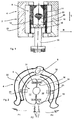
- FIGS. 4a-4c show a further embodiment of a holding piece 60, which engages the blow mold from the outside.
- the holding piece 60 could be moved in the form of a plastic clip with an inlet star in an open mold.
- This holding piece has a multiplicity of holding webs 64 or clips extending in the radial direction of the blow mold. These holding webs are each arranged on a base body 68.
- This base body has on the one hand a circumferential groove 66, in which a gripping clip can engage.
- the base body may also have an opening, so that other gripping elements, such as holding thorns can engage in it.
- Reference numeral 64a refers to holding hooks formed in an outer periphery of the blow moldings 12, 14 engage, for which purpose the blow mold may for example have a circumferential groove.
- the holding piece and lower support ribs 72 which are arranged with the blow mold closed inside it and are supported against the inner wall 7 of the blow mold 6.
- clips or their hooks 64a can grip over the mold, preventing stripping of the fuse by the inner arms or support webs, which bear against the bottle contour, for example, and thus pull the holding element 60 downwards. Dismantling is possible by pulling up or lifting the said clips.
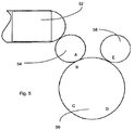
- Fig. 5 illustrates the method according to the invention.
- the reference numeral 52 denotes a heater for heating the preforms
- the reference numeral 54 an inlet star
- the reference numeral 56 a blowing wheel on which a plurality of blowing stations of in Fig. 1 shown type can be arranged
- the reference numeral 58 an outlet star.
- the holding element as explained above, be plugged and snap in a position B, already on the blowing wheel of this holding element in the blow mold 6.
- the water connections can be decoupled and the area D of the blow mold 6 can be unlocked from the blow mold carrier 4.
- a region E it would be possible to remove the holding element 40 together with the blow mold.
- a holding element with a pre-oriented shape can be attached.
- an orientation of the shape can take place.
- the mold can be fixed on a carrier, in a region D the water connections are coupled and a region E with the carrier open, the holding element 40 are removed.
- the exact orientation of the blow mold can be done while closing the mold carrier halves. For example, such an orientation over lugs on the mold carrier 4 is possible.
- the mold is closed, both the water connections are coupled and the mold is fixed in mold carrier 4, whereby, as mentioned above, this can also take place via delivered curves.
- the holding element 40 is disengaged and removed via an outlet star 58.
Description
- Die vorliegende Erfindung bezieht sich auf eine Umformeinrichtung zum Umformen von Kunststoffvorformlingen zu Kunststoffbehältnissen sowie ein Verfahren zur Montage / Demontage hierzu gehöriger Blasformen. Im Stand der Technik, siehe z.B.
US 5232716 ,DE 69123305 T2 undWO 2006113428 , sind seit längerer Zeit Umformungseinrichtungen wie beispielsweise Blasumformungseinrichtungen bekannt, welche Kunststoffvorformlinge zu Kunststoffbehältnissen umformen. Zu diesem Zweck weisen derartige Vorrichtungen üblicherweise so genannte Blasformen auf, welche zusammengeklappt werden können und in ihrem Inneren einen Hohlraum ausbilden, der zur Expansion eines Kunststoffvorformlings gegen die Wandung des Hohlraumes dient, um so Kunststoffbehältnisse zu erzeugen. - Diese Blasformen weisen daher üblicherweise zwei Blasformhälften auf, die in entsprechenden Blasformenträgern angeordnet werden.
- Falls eine entsprechende Vorrichtung auf andere Flaschentypen umgerüstet werden soll ist hierzu erforderlich, dass die Blasformen von dem Blasformträger entnommen und durch andere Blasformen ersetzt werden. Dieser Vorgang ist dabei relativ zeitintensiv, da insbesondere für eine Vielzahl von Blasstationen jede einzelne Blasform von ihrem Träger entnommen werden muss.
- Aus diesem Grunde sind aus dem Stand der Technik diverse Koppelmechanismen bekannt, welche ein möglichst schnelles Trennen der Blasformen von ihren Formträgern erlauben. Derartige Schnelllösemechanismen ermöglichen dabei zum Teil eine sehr zügige Auswechslung der jeweiligen Blasformen. Gleichwohl wird nach noch schnelleren Möglichkeiten für derartige Blasformwechsel gesucht.
- Der folgenden Erfindung liegt daher die Aufgabe zu Grunde, die Montage / Demontage von derartigen Blasformen schneller zu gestalten. Eine weitere Aufgabe ist darin zu sehen, derartige Blasformwechsel gegebenenfalls auch automatisiert durchzuführen.
- Diese Aufgaben werden erfindungsgemäß durch die Gegenstände der unabhängigen Ansprüche erreicht. Vorteilhafte Ausführungsformen und Weiterbildungen sind Gegenstand der Unteransprüche.
- Bei dem Verfahren zur Demontage von Blasformen aus einer Umformeinrichtung zum Umformen von Künststoffvorformlingen zu Kunststoffbehältnissen weist diese Umformeinrichtung wenigstens einen Blasformträger und eine in diesem Blasformträger angeordnete mehrteilige Blasform auf. Erfindungsgemäß wird die Blasform in einem wenigstens teilweise zusammengesetzten Zustand von dem - bevorzugt mehrteilig ausgebildeten - Blasformträger getrennt.
- Während im Stand der Technik bisher üblicherweise zunächst die Blasformträger mit den Blasformhälften geöffnet werden und anschließend separat die beiden Blasformseitenteile von dem Blasformträger getrennt werden, wird vorgeschlagen, die Blasform in ihrer Gesamtheit aus dem Blasformträger zu entnehmen. Hierunter ist zu verstehen, dass die einzelnen Blasformteile zum Zeitpunkt der Entnahme aus dem Blasformträger fest miteinander verbunden sind, sodass ein einfaches Handhabungsinstrument ausreicht, um die Entnahme durchzuführen. Weiterhin ist es aber auch denkbar, dass die einzelnen Blasformteile zum Zeitpunkt der Entnahme nicht miteinander verknüpft sind. Allerdings ist der Vorgang so synchronisiert, dass die Blasformteile in etwa zeitgleich aus dem Blasformträger entnommen werden können. Weiterhin ist es auch vorstellbar, dass lediglich einzelne Teile der mehrteiligen Blasform zum Zeitpunkt der Entnahme miteinander verknüpft sind. Der zentrale Punkt ist auch dann wieder die in etwa gleichzeitig stattfindende Entnahme der Blasformteile aus dem Blasformträger. Durch diese Vorgehensweise können die Wechselzeiten zum Demontieren der Blasformen verringert werden.
- Es wird daraufhin gewiesen, dass das erfindungsgemäße Verfahren auch entsprechende Anwendung auf die Montage von Blasformen Anwendung finden kann, indem eine Blasform in wenigstens teilweise zusammengesetzten Zustand mit dem Blasformträger verbunden wird.
- Durch die erfindungsgemäße Vorgehensweise ist es auch möglich, einen auch im Arbeitsbetrieb der Vorrichtung nötigen Öffnungsvorgang der Blasformträger zu nutzen um die Blasform aus den Trägern zu entnehmen.
- Bei dem bevorzugten Verfahren wird in einem ersten Verfahrensschritt die Blasform von dem Blasformträger getrennt und anschließend die Blasform in wenigstens teilweise zusammengesetzten Zustand von der Umformeinrichtung entfernt.
- Unter einem wenigstens teilweise zusammengesetzten Zustand wird verstanden, dass wenigstens zwei Bestandteile dieser Blasform im Wesentlichen zusammengesetzt sind. Dabei kann es sich beispielsweise um zwei Seitenteile dieser Blasform handeln, die gemeinsam einen Hohlraum zur Umformung der Kunststoffvorformlinge zu Kunststoffbehältnissen umgeben und welche im Wesentlichen zusammengesetzt sind. Unter im wesentlich zusammengesetzt wird wiederum verstanden, dass die beiden Seitenteile nicht unbedingt vollständig aneinander liegen müssen, wie dies beispielsweise bei diesem Arbeitsbetrieb der Fall ist, sondern dass beispielsweise auch ein Zwischenraum zwischen den Seitenteilen vorgesehen sein kann, wobei jedoch dennoch ein zumindest indirekt vermittelter Halt zwischen den beiden Teilen der Blasform besteht.
- Bei dem Verfahren weist die Blasform zwei Blasformhälften auf und diese Blasformhälften sind mit einem Haltemittel aneinander befestigt, während die Blasform von dem Blasformträger getrennt wird. Dabei kann es sich um ein Haltemittel handeln, welches an beiden Blasformhälften angeordnet ist und diese miteinander verbindet. Es könnte sich jedoch auch um ein Haltemittel handeln, welches beispielsweise in einem Boden der Vorrichtung angeordnet ist auf dem die beiden Blasformhälften aufsitzen. Durch diese Vorgehensweise können die Blasformträger geöffnet und anschließend die Blasform aus der Umformeinrichtung entnommen werden.
- Weiter weist die Blasform ein Bodenteil auf und dieses Bodenteil ist an wenigstens einer Blasformhälfte befestigt, während die Blasform von dem Blasformträger getrennt wird. Vorteilhaft weisen die beiden Blasformhälften Ausnehmungen auf, welche das Bodenteil aufnehmen und beispielsweise zwischen sich einspannen. So ist es möglich, dass das Bodenteil an beiden Blasformhälften angeordnet und insbesondere in beide Blasformhälften eingehängt ist.
- Bei einem weiteren bevorzugten Verfahren werden die Blasformhälften derart an dem Bodenteil arretiert, dass sich der Formträger beim Öffnen desselben von den Blasformhälften löst. So kann vorgesehen sein, dass in einem speziellen Montage- oder Demontage - Betrieb der Umformeinrichtung zunächst eine Verriegelung zwischen dem Formträger und der Blasform geöffnet wird und anschließend die Formträger geöffnet werden und schließlich die Blasform entnommen wird.
- Bei einem weiteren bevorzugten Verfahren wird die Blasform nach der Trennung von dem Blasformträger mittels einer Transporteinrichtung transportiert. Auf diese Weise kann zu einer Automatisierung des Blasformwechsels beigetragen werden, indem nicht nur die Blasform im zusammengesetzten Zustand von den Formträgern entfernt wird, sondern anschließend auch mit einer Transporteinrichtung abtransportiert wird.
- Vorteilhaft wird die Blasform in einem Greif- oder Halteelement transportiert, welches auch zum Transport der Behältnisse dient. So ist es möglich, dass die gleichen Halteelemente und Transportwege auch zur Demontage der Blasformen eingesetzt werden können, die auch im Arbeitsbetrieb zum Transport der Behältnisse dienen. Auf diese Weise kann eine weitere Automatisierung und auch Vereinfachung des Systems erreicht werden.
- Das Verfahren ist auch anwendbar, wenn der Aufbau einer Blasstation einen äußeren Formträger, eine mittlere Mutterform sowie eine innere Blasform aufweist. Der erfindungsgemäße Vorgang umfasst dabei sowohl das Entfernen der Blasformteile aus dem Blasformträger und der damit verbundenen Mutterform, als auch das Entfernen der Mutterform und der Blasformteile aus dem Blasformträger.
- Die vorliegende Erfindung ist daher weiterhin auf ein Verfahren zur Montage und/oder Demontage von Blasformen aus oder in Vorrichtungen zum Umformen von Kunststoffvorformlingen zu Kunststoffbehältnissen gerichtet, wobei die Blasform in einem wenigstens teilweise zusammengesetzten Zustand mittels einer Transporteinrichtung entlang eines durch die Transporteinrichtung vorbestimmten Transportpfades transportiert wird.
- Vorzugsweise handelt es sich bei der Transporteinrichtung um eine solche Transporteinrichtung, welche auch zum Transportieren der Kunststoffvorformlinge und/oder der Kunststoffbehältnisse verwendet wird. Vorteilhaft wird die Blasform wenigstens teilweise auf einem kreisförmigen Transportpfad transportiert. So ist es möglich, dass die Blasform über einen Einlaufstern zur Montage an Blasformträger herangeführt wird und/oder über einen Auslaufstern von einem Blasformträger weggeführt wird.
- Die vorliegende Erfindung ist weiterhin auf eine Umformeinrichtung zum Umformen von Kunststoffvorformligen zu Kunststoffbehältnissen mit einer mehrteilig ausgebildeten Blasform gerichtet, wobei diese Blasform einen Hohlraum ausbildet, innerhalb dessen die Kunststoffvorformlinge zu den Kunststoffbehältnissen expandierbar sind. Weiterhin weist die Umformeinrichtung einen Blasformträger auf, an dem die Blasform lösbar angeordnet ist.
- Erfindungsgemäß ist ein Haltemittel vorgesehen, welches wenigstens zwei Teile der Blasform in einem von dem Blasformträger gelösten Zustand aneinander befestigt.
- Auch vorrichtungsseitig wird daher vorgeschlagen, dass insbesondere die Blasform derart ausgeführt ist, dass die Blasform aus der Anlage nach einer Trennung von dem Blasformträger in einem zumindest teilweise zusammengesetzten Zustand entnommen werden kann. Auch wird vorgeschlagen, dass die Blasform in diesem Zustand transportierbar ist. Vorteilhaft setzt sich die Blasform aus wenigstens zwei Seitenteilen und einem Bodenteil zusammen. Das Haltemittel dient bevorzugt in diesem Zustand dazu, dass Blasform in ihrer Gesamtheit, dass heißt die Seitenteile und das Bodenteil entnommen und transportiert werden können.
- Bei diesem Haltemittel kann es sich beispielsweise um ein Greifmittel handeln, welches die beiden Blasformteile aufeinander zu spannt. Auch könnten magnetische Mittel in den Blasformhälften vorgesehen sein, welche durch Magnetkraft die beiden Blasformhälften aneinander halten. Insbesondere weist der Blasformträger wenigstens zwei gegeneinander schwenkbare Trägerhälften auf, wobei bevorzugt jede Trägerhälfte ein Seitenteil der Blasform enthält.
- Die Blasformhälften sind vorteilhaft symmetrisch zueinander ausgebildet. Auch ist es möglich, dass die Blasformhälften zur gemeinsamen Aufnahme einer weiteren Mutterform dienen, innerhalb derer die Kunststoffvorformlinge zu den Kunststoffbehältnissen expandiert werden.
- In einem normalen Arbeitsbetrieb werden die beiden Blasformhälften lediglich zur Expansion der Behältnisse zusammengeklappt, sind aber ansonsten vollkommen voneinander getrennt. Auch das erfindungsgemäße Haltemittel erlaubt damit eine Entnahme der Blasform in ihrer Gesamtheit aus dem Blasformträger.
- Bei einer weiteren vorteilhaften Ausführungsform steht der Blasformträger über einen - vorteilhaft automatisch - lösbaren Verbindungsmechanismus mit der Blasform in Verbindung. Damit wird zunächst dieser Verbindungsmechanismus im Falle einer Demontage gelöst um anschließend die Blasform zu entnehmen. Im Falle der Montage wird zunächst die Blasform zwischen die Blasformträger eingesetzt und anschließend wird der lösbare Verbindungsmechanismus verriegelt um die beiden Blasformhälften in dem Formträger anzuordnen.
- Bei einer weiteren vorteilhaften Ausführungsform sind die zwei Teile der Blasform unmittelbar aneinander mit dem Haltemittel befestigt.
- Bei einer weiteren vorteilhaften Ausführungsform ist die Blasform an einem Halteelement befestigbar, welches in einem Arbeitsbetrieb zum Transportieren der Behältnisse dient. So ist es beispielsweise möglich, dass die Blasform über magnetische Kräfte an dem Halteelement angeordnet ist.
- Bei einer weiteren vorteilhaften Ausführungsform ist jedoch ein Haltestück vorgesehen, welches sowohl mit der Blasform als auch mit einem Halteelement, welches in einem Arbeitsbetrieb zum Transportieren der Behältnisse dient, in Verbindung bringbar ist. So könnte ein Haltestück vorgesehen sein, welches in einen Mündungsbereich der Blasform eingeführt wird und diesem gegenüber nicht entnommen werden kann solange die beiden Blasformhälften miteinander verbunden sind. Das andere Ende dieses Haltestücks könnte so ausgeführt sein, dass es von einem Halteelement der Anlage gehalten werden kann. Auf diese Weise können die bereits vorhandenen Transporteinrichtungen genutzt werden, um auch die Blasform selbst abzutransportieren. Vorteilhaft ist das Haltestück einteilig ausgebildet.
- Bei einer weiteren vorteilhaften Ausführungsform ist das Haltestück mit zwei Teilen der Blasform zum Halten der Blasform in Eingriff bringbar. So ist es möglich, dass dieses Haltestück wie erwähnt, zwischen den beiden Blasformhälften aufgenommen wird und in diesem Falle nicht mehr herausgezogen werden kann.
- Der Gegenstand ist weiterhin auf ein Haltestück gerichtet, welches einen ersten Halteabschnitt aufweist, der mit einer geschlossenen Blasform in Verbindung bringbar ist sowie einem zweiten Halteabschnitt, der von einem Halteelement und insbesondere einem Greifelement, welches zum Halten von Behältnissen dient, greifbar ist.
- Vorzugsweise weist dieses Haltestück ein Eingriffsmittel auf, welches in einen inneren Hohlraum in der Blasform eindringt und welches wenigstens abschnittsweise einen größeren Querschnitt aufweist als ein Halsabschnitt dieser Blasform. Auf diese Weise kann das Haltestück nicht von der Blasform getrennt werden. Es wäre jedoch auch möglich, dass das Haltestück ein Eingriffsmittel aufweist, welches an einem Außenumfang zweier Seitenteile der Blasform angreift um diese beiden Seitenteile zusammen zu halten.
- Weitere Vorteile und Ausführungsformen ergeben sich aus den beigefügten Figuren:
- Dabei zeigen:
- Fig. 1
- eine schematische Darstellung eines Blasformträgers mit einer Blasform;
- Fig. 2
- eine schematische Draufsicht auf einen Blasformträger mit einer Blasform;
- Fig. 3a - 3d
- vier Darstellungen zur Veranschaulichung eines Haltestücks für eine Blasform;
- Fig. 4a - 4c
- drei Darstellungen zur Veranschaulichung eines weiteren Haltestücks für eine Blasform; und
- Fig. 5
- eine grobschematische Darstellung einer erfindungsgemäßen Anlage zum Behandeln von Behältnissen.
-
Fig. 1 zeigt eine grob schematische Darstellung einer Blasstation 2. Diese Blasstation 2 weist hier einen in seiner Gesamtheit mit 4 bezeichneten Blasformträger auf. Dieser Blasformträger weist zwei Trägerhälften 22 und 24 auf, welche im Arbeitsbetrieb die Blasform aufnehmen. Genauer setzt sich die Blasform 6 ebenfalls aus zwei Blasformteilen bzw. Blasformhälften 12 und 14 zusammen, wobei die erste Blasformhälfte 12 an einer ersten Trägerhälfte 22 befestigt ist und eine zweite Blasformhälfte 14 an einer zweiten Trägerhälfte 24. Ein entsprechender Befestigungsmechanismus ist inFig. 1 jedoch nicht dargestellt. - Weiterhin weist die Blasform 6 noch ein Bodenteil 16 auf, welches gemeinsam mit den beiden Blasformteilen 12 und 14 einen Hohlraum 15 ausbildet, innerhalb dem (nicht gezeigte) Kunststoffvorformlinge zu den Behältnissen expandiert werden. Das Bezugszeichen 36 bezieht sich auf ein Zustellelement, welches das Bodenteil 16 in einem Arbeitsbetrieb an die beiden Seitenteile 12 und 14 der Blasform heranführt.
- Das Bezugszeichen 30 zeigt grob schematisch eine Befestigungseinrichtung, welche die beiden Blasformhälften zur Entnahme der Blasform in einem geschlossenen Zustand aneinander befestigt. Dabei kann es sich beispielsweise um entgegengesetzt polarisierte Magneten handeln, welche die beiden Blasformhälften aneinander halten. Um zu verhindern, dass die Blasformhälften auch im Arbeitsbetrieb aneinander gehalten werden sind unterschiedliche Möglichkeiten denkbar. So könnte beispielsweise einer der beiden Magneten gegenüber dem anderen in einer Längsrichtung L der Blasform verschiebbar sein, so dass im Arbeitsbetrieb keine Magnetkraft zwischen den beiden Blasformteilen 12 und 14 entsteht. Weiterhin wäre es auch möglich, dass einer oder beide Magneten in radialer Richtung R der Blasform jeweils nach innen verschoben wird so dass ebenfalls eine Magnetkraft im Arbeitsbetrieb zwischen den beiden Blasformteilen 12 und 14 minimiert oder auf null reduziert wird.
- Weiterhin wäre es auch möglich, dass in einer der beiden Blasformhälften eine Vielzahl von jeweils abwechselnd polarisierten Magneten in der Längsrichtung L angeordnet ist und weiterhin ein Schiebeelement vorgesehen ist, welches entsprechend der Teilung dieser Magneten magnetisierbare Flächen aufweist wobei dieses Element in der Richtung L verschiebbar gegenüber den Magneten ist. Je nach Stellung dieses Verschiebeelements decken die Flächen entweder die Magnete ab so dass die Magnetkraft vermittelt wird oder stehen zwischen diesen Magneten so dass die Magnete kurzgeschlossen werden und auf diese Weise die Magnetkraft erheblich reduziert wird.
- Die Befestigungseinrichtung setzt sich also hier aus mindestens zwei Magneten 31, 32 zusammen, wobei der Magnet 31 an der ersten Blasformhälfte 12 und der andere Magnet an der zweiten Blasformhälfte 14 angeordnet ist. So könnten die beiden Blasformhälften Ausnehmungen aufweisen, in denen die beiden Magneten 31, 32 angeordnet sind. Auch könnte nur ein Magnet vorgesehen sein, der einen magnetischen Abschnitt der jeweils anderen Blasformhälfte anzieht. Die Magneten könnten auch in einer Längsrichtung L der Blasform verschiebbar sein, um den magnetischen Halt zu lösen bzw. zu bilden.
- Daneben wären jedoch auch andere (insbesondere mechanische) Halteelemente denkbar, welche die beiden Blasformteile 12, 14 aneinander halten wie beispielsweise mechanische Halteriegel oder dergleichen mit denen nach Wunsch die beiden Blasformhälften miteinander gekoppelt werden können. Derartige Verriegelungselemente könnten auch automatisch, beispielsweise über eine Führungskurve, angesteuert werden.
- Wie erwähnt, wird in einem Demontagebetrieb zunächst der Blasformträger 4 von der Blasform 6 gelöst und anschließend kann die Blasform in ihrer Gesamtheit aus der Maschine entnommen werden. Es wäre jedoch auch eine Entnahme in Längsrichtung d.h. senkrecht zu der Figurenebene möglich.
-
Fig. 2 zeigt eine weitere Darstellung einer erfindungsgemäßen Blasstation. Auch hier ist ein Zustand dargestellt, in dem die Blasformträger 22 und 24 teilweise geöffnet sind und die Blasform selbst in einem verschlossenen Zustand angeordnet ist. In diesem Zustand kann die Blasform im geschlossenen Zustand entlang des Pfeils P2 aus dem Blasformträger, dessen beiden Seitenteile 22 und 24 entlang der Pfeile P1 nach außen geschwenkt sind, entnommen werden. - Weiterhin wäre es auch möglich, einen Verriegelungsmechanismus, der die beiden Blasformhälften 12 und 14 an den jeweiligen Trägerhälften 22 und 24 befestigt, zu koppeln mit einem Verriegelungsmechanismus der beiden Blasformhälften 12 und 14. So könnte diese Koppelung derart gestaltet sein, dass bei einem Entriegeln der Blasformhälften 12 und 14 gegenüber den Trägerhälften 22 und 24 gleichzeitig ein Verriegeln der beiden Blasformhälften 12 und 14 auftritt.
- Damit kann zum Entnehmen der Blasform bzw. Formwechselteile die Vorrichtung und die Handhabung derart konzipiert sein, dass Umrüstzeit eingespart wird. Diese Zeiteinsparung ergibt sich hauptsächlich aus dem gemeinsamen Herausnehmen bzw. Einsetzen der Blasform d. h. der beiden Formhälften 12 und 14 und der Bodenform 16 so dass nur noch ein Vorgang statt wie im Stand der Technik drei unterschiedliche Vorgänge notwendig sind.
- Daneben ist es auch möglich, dass die Blasform gemeinsam gelagert wird und nicht wie bisher die einzelnen Bestandteile der Blasform gelagert werden. Durch diese gemeinsame Lagerung wird zum einen weniger Lagerplatz benötigt aber zum anderen können auch die zusammengehörigen Formteile 12, 14 und 16 schnell aufgefunden werden.
- Damit werden zur Demontage zunächst die beiden Formhälften 12, 14 beim geschlossenen Formträger von diesem Formträger 4 entriegelt. Dies ist, wie erwähnt, eine Änderung zu der heutigen Vorgehensweise. Erst wenn die beiden Formhälften von dem Formträger entriegelt sind werden die beiden Formträger 22 und 24 geöffnet wobei dieses Öffnen sowohl manuell als auch automatisch erfolgen kann.
- Durch die erwähnte Befestigungseinrichtung 30 bleiben die beiden Blasformhälften 12 und 14 zusammen wobei, wie erwähnt, neben der magnetischen Verbindung auch beispielsweise eine Schnappverbindung in Frage kommen kann. Die Formträger 22 und 24 haben sich dann soweit von den Formhälften 12 und 14 entfernt dass die Formhälften gemeinsam auf der Bodenform 16 (vgl.
Fig. 1 ) frei stehen. Vorteilhaft sind dabei die Formhälften 12 und 14 auf die Bodenform 16 zueinander am Umfang und auch axial fixiert um ein positionsgenaues Wiedereinsetzen zu gewährleisten. Die so zusammenhängenden Formwechselteile 12, 14 und 16 stehen frei zum Entnehmen und können manuell oder vollautomatisch entnommen und gelagert werden. - Aus einem entsprechenden Magazin, dass so konzipiert, ist das alle Teile gemeinsam gelagert werden können die einzusetzenden Formsätze gemeinsam entnommen werden und somit Zeit zum Zusammensuchen eingespart werden.
- Auch in umgekehrter Reihenfolge zum Montieren der Blasformen 6 können die zusammenhängenden Formwechselteile 12, 14 und 16 eingesetzt werden. Anschließend wird die Bodenform mit den darauf fixierten Formhälften 12 und 14 positioniert und in einem nächsten Schritt können die beiden Formträger 22 und 24 schließen. Erst in einem letzten Schritt werden wiederum die Blasformhälften 12 und 14 mit den jeweiligen Trägerhälften 22 und 24 verriegelt, um die Änderung in einen arbeitsbereiten Zustand zu versetzen.
- Vorzugsweise wäre es auch möglich, die Verbindung der beiden Formhälften 12 und 14 über das Bodenteil 16 herzustellen. So können die beiden Formhälften 12 und 14 (ggfs.) auf dem Bodenteil 16 oder auch direkt miteinander so arretiert werden dass sich der Formträger 4 beim Öffnen von der Blasform bzw. deren Bestandteilen 12 und 14 gelöst.
- Das Bezugszeichen 25 veranschaulicht grob schematisch einen Verbindungsmechanismus, über den die Trägerteile 22, 24 mit der Blasform 6, bzw. deren Blasformhälften in Verbindung stehen. Vorzugsweise handelt es sich dabei um einen automatisch lösbaren Verbindungsmechanismus, der beispielsweise über eine Führungskurve gelöst oder geschlossen werden kann. Dieser Verbindungsmechanismus weist bevorzugt mehrere Halteelemente auf, mit denen die Blasformteilen an den Trägerteilen 22, 24 gehalten werden. Auch könnte dieser Verbindungsmechanismus magnetische Haltelemente aufweisen. Daneben könnte die Verbindung zwischen der Blasform und den Trägerteilen auch durch einen Unterdruck erzeugt werden.
- Vorteilhaft können gemeinsam mit dem Verbindungsmechanismus auch Kühlmittelanschlüsse an die Blasform 6 angelegt werden, um diese mit einem insbesondere flüssigen Temperiermittel bzw. allgemein mit einem Temperiermittel zu versorgen. Diese Anschlüsse könnten dabei ebenfalls automatisch lösbar bzw. verbindbar sein.
- Die
Fig. 3a - 3d zeigen unterschiedliche Stationen zum Entnehmen einer Blasform. Bei der inFig. 3a gezeigten Situation ist in einem Produktionsmodus ein geschlossener Formträger 4 mit einer darin eingesetzten Blasform 6 gezeigt. Genauer gesagt sind hier die beiden Blasformteile 12 und 14 an den entsprechenden Trägerteilen 22 und 24 fest angeordnet so dass bei einem Auseinanderklappen der beiden Trägerhälften 22 und 24 auch die Blasformteile 12 und 14 mitbewegt werden. Das Bezugszeichen 17 kennzeichnet einen Eingriffsbereich, mit dem bei einem Zusammenklappen der beiden Blasformteile 12 und 14 auch ein Bodenteil 16 eingehakt wird. Das Bodenteil 16 kann über einen Zustellmechanismus 19 an die beiden Formteile 12 und 14 herangeführt werden wobei dieser Zustellmechanismus 19 eine Ausnehmung 21 aufweist, in welche wiederum ein entsprechend angepasster Vorsprung 23 des Bodenteils 16 eingreift. -
Fig. 3b zeigt einen geöffneten Zustand der beiden Blasformträger 22 und 24 mit den darin arretierten Blasformteilen 12 und 14. Das Bezugszeichen 13 bezieht sich auf einen Eingriffsbereich, mittels dem die Blasformteile 12 und 14 jeweils an den Blasformträgern 12 und 14 arretiert sind. In diesem geöffneten Zustand des Formträgers 4 kann ein Halteelement 40 in das Innere der Blasform 6 eingebracht werden wobei dieses Halteelement insbesondere zum Transport der Blasform 6 dient. Dieses Halteelement weist einen Eingriffsabschnitt 42 auf, dessen Querschnitt größer ist als ein Öffnungsquerschnitt der Blasform 6 im geschlossenen Zustand. -
Fig. 3c zeigt einen geschlossenen Zustand mit eingesetztem Halteelement 40. Man erkennt, dass das Halteelement 40 aufgrund seiner Ausgestaltung bzw. des Eingriffsbereichs 42 nicht aus der Blasform 6 entnommen werden kann. Vielmehr kann mit Hilfe dieses Halteelements die Blasform 6 transportiert werden. Bei der inFig. 3d gezeigten Situation wurde der Träger wie inFig. 2 veranschaulicht, geöffnet so dass nunmehr die Blasform 6 gemeinsam mit den Formteilen 12 und 14 sowie dem Bodenteil 16 mit Hilfe des Halteelements 40 entnommen werden kann. Zu diesem Zweck weist das Halteelement Ausnehmungen 44 (vgl.Fig. 3c ) auf, in welche eine Greifeinrichtung bzw. Greifklammer 28 eingreifen kann, welche im Normalbetrieb der Anlage auch zum Transportieren der Behältnisse dient. Diese Greifeinrichtung kann die Blasform (ggfs. auch über die im Normalbetrieb üblichen Transportwege) abtransportieren beispielsweise zu einem Magazin. Weiterhin kann auf diese Weise die Blasform auch zu einer Reinigungsstation transportiert werden, in der ein ggfs. automatisches Reinigen der Blasform möglich ist. - Dabei können die einzelnen Bewegungen, die zum Einführen des Halteelements 40 bzw. auch zum Transportieren der Blasform dienen, aus einer Bewegung aus einem normalen Arbeitsbetrieb der Anlage abgeleitet werden.
- Bei einer nicht in den Figuren dargestellten Vorgehensweise wird das Haltestück bzw. der Dummy mit den Formhälften 12 und 14 und der Bodenform 16 vororientiert auf einen Einlaufstern gesteckt. Weiterhin kann die Blasform 6 bei einer Eingabe orientiert und dabei im vorgegebenen Winkel beispielsweise 20 Grad gedreht in die Formträger 4 eingebracht werden. Bei dieser Ausführungsform ist das Haltestück wenigstens zeitweise drehfest mit der Blasform verbunden.
- In einem weiteren Schritt wird vorteilhaft das Haltestück, beispielsweise über eine Zahnstange, gedreht bis die Blasformteile 12 und 14 und das Bodenteil 16 in den Blasformträger einrasten. In einem weiteren Schritt können die Wasseranschlüsse für die Blasformteile und das Bodenteil 16 vorzugsweise kurvengesteuert verriegelt werden. Schließlich kann die Blasform 6 geöffnet werden und das Haltestück 40 beispielsweise über einen Auslaufstern entnommen werden.
- Damit übernimmt hier das Halteelement die Aufgabe, die beiden Formhälften 12 und 14 sowie den Boden aufzunehmen so dass die gesamte Blasform 6 oder zumindest beide Blasformhälften 12 und 14 auf einmal aus dem geöffneten Formträger 4 entnommen werden können. Bei einer möglichen Ausführungsform des Halteelements 40 wird dieses über einen Transferarm wobei es sich hier sogar um den Einlaufstern der Maschine handeln kann in die sich schließende Form eingegeben. Beim Schließen der beiden Blasformhälften rasten diese wie in
Fig. 3b gezeigt in das Halteelement 40 ein. Beim weiteren Drehen der Blasmaschine werden die Blasformen 6 von dem Blasformträger 4 gelöst. Dies kann, wie oben erwähnt, beispielsweise durch eine kurvengesteuerte Verriegelung geschehen. Daneben können auch evtl. vorhandene Wasseranschlüsse über Kurven entkoppelt werden. - Bei dem nachfolgenden Öffnen der Formträger 4 bleiben die an dem Halteelement 40 arretierten Blasformhälften 12 und 14 geschlossen und das Halteelement kann gemeinsam mit der Blasform 6 beispielsweise mit einem Transferarm entnommen werden, wobei es sich bei diesem Transferarm auch um den Auslaufstern einer Anlage handeln kann. Anschließend kann die gesamte Blasform 6 mitsamt dem Halteelement 40 an diesem Halteelement in ein Magazin eingehängt werden.
- Die
Figuren 4a - 4c zeigen einer weitere Ausführungsform eines Haltestücks 60, welches die Blasform von außen greift. So könnte beispielsweise das Haltestück 60 in Form eines Kunststoffclips mit einem Einlaufstern in eine offene Form gefahren werden. Dieses Haltestück weist eine Vielzahl von sich in radialer Richtung der Blasform erstreckenden Haltestegen 64 bzw. Clipse auf. Diese Haltestege sind jeweils an einem Grundkörper 68 angeordnet. Dieser Grundkörper weist dabei einerseits eine umlaufende Nut 66 auf, in welche eine Greifklammer eingreifen kann. Daneben kann der Grundkörper jedoch auch noch eine Öffnung aufweisen, damit auch andere Greifelemente, wie beispielsweise Haltedorne in es eingreifen können. Das Bezugszeichen 64a bezieht sich auf Haltehaken, die in einen Außenumfang der Blasformteile 12, 14 eingreifen, wobei zu diesem Zweck die Blasform beispielsweise eine Umfangsnut aufweisen kann. - Wie in
Fig. 4b erkennbar, weist das Haltestück auch untere Stützstege 72 aus, die bei geschlossener Blasform im Inneren derselben angeordnet sind und sich gegen die Innenwandung 7 der Blasform 6 abstützen. Wenn sich die Form schließt können Clipse bzw. deren Haken 64a über die Form greifen wobei ein Abstreifen der Sicherung durch die inneren Arme bzw. Stützstege verhindert wird die sich beispielsweise an die Flaschenkontur anlegen und so das Halteelement 60 nach unten ziehen. Die Demontage ist durch Abziehen nach oben oder Anheben der besagten Clipse möglich. -
Fig. 5 veranschaulicht das erfindungsgemäße Verfahren. Dabei kennzeichnet das Bezugszeichen 52 eine Heizeinrichtung zum Erwärmen der Vorformlinge, das Bezugszeichen 54 einen Einlaufstern, das Bezugszeichen 56 ein Blasrad, an dem eine Vielzahl von Blasstationen der inFig. 1 gezeigten Art angeordnet sein können und das Bezugszeichen 58 einen Auslaufstern. In dem Bereich A kann das Halteelement, wie oben erläutert, aufgesteckt werden und in einer Position B, bereits auf dem Blasrad dieses Halteelements in die Blasform 6 einrasten. In dem Bereich C können die Wasseranschlüsse entkoppelt werden und dem Bereich D die Blasform 6 von dem Blasformträger 4 entriegelt werden. In einem Bereich E wäre es möglich, das Halteelement 40 mitsamt der Blasform zu entnehmen. - Beim Einbringen einer neuen Form kann das erläuterte Prinzip umgekehrt werden. So kann in einem Bereich A ein Halteelement mit einer vororientierten Form aufgesteckt werden. In einem Bereich B kann eine Orientierung der Form stattfinden. In einem Bereich C kann die Form auf einen Träger fixiert werden, in einem Bereich D die Wasseranschlüsse angekoppelt werden und einem Bereich E bei geöffnetem Träger das Halteelement 40 entnommen werden. Auch hier ist es wiederum möglich, die Blasform 4 über einen Transferarm einzubringen. Das genaue Orientieren der Blasform kann erfolgen, während die Formträgerhälften schließen. Beispielsweise ist eine derartige Orientierung über Nasen am Formträger 4 möglich. Bei geschlossener Form werden sowohl die Wasseranschlüsse angekoppelt als auch die Form in Formträger 4 fixiert wobei dies wie erwähnt auch wieder über zugestellte Kurven ablaufen kann. Beim Öffnen der Blasformhälften 12 und 14 wird das Halteelement 40 ausgerastet und über einen Auslaufstern 58 entnommen.
-
- 2
- Blasstation
- 4
- Blasformträger
- 6
- Blasform
- 7
- Innenraum der Blasform 6
- 12, 14
- Blasformhälfte
- 15
- Hohlraum
- 16
- Bodenteil
- 13, 17
- Eingriffsbereich
- 19
- Zustellmechanismus
- 21
- Ausnehmung
- 22, 24
- Trägerhälte, Blasformträger
- 23
- Vorsprung
- 25
- Verbindungsmechanismus
- 28
- Greifklammer
- 30
- Befestigungseinrichtung
- 31, 32
- Magnete
- 36
- Zustellelement
- 40
- Haltestück
- 42
- Eingriffsabschnitt
- 44
- Ausnehmungen
- 52
- Heizeinrichtung
- 54
- Einlaufstern
- 56
- Blasrad
- 58
- Auslaufstern
- 60
- Haltestück
- 64
- Haltesteg
- 64a
- Haltehaken
- 66
- umlaufende Nut
- 68
- Grundkörper
- 72
- (untere) Stützstege
- L
- Längsrichtung
- P1,P2
- Pfeile
- R
- radiale Richtung
Claims (11)
- Verfahren zur Demontage von Blasformen aus einer Umformeinrichtung zum Umformen von Kunststoffvorformlingen zu Kunststoffbehältnissen, wobei diese Umformeinrichtung (2) wenigstens einen Blasformträger (4) und eine an diesem Blasformträger (4) angeordnete mehrteilige Blasform (6) aufweist,
wobei
die Blasform (6) in wenigstens teilweise zusammengesetzten Zustand von dem Blasformträger (4) getrennt wird, und
die Blasform zwei Blasformhälften (12, 14) aufweist und diese Blasformhälften (12, 14) mit einem Haltemittel (22) aneinander befestigt sind, während die Blasform (6) von dem Blasformträger (4) getrennt wird, dadurch gekennzeichnet, dass die Blasform ein Bodenteil (16) aufweist und dieses Bodenteil (16) an wenigstens einer Blasformhälfte (12, 14) befestigt ist, während die Blasform (6) von dem Blasformträger (4) getrennt wird. - Verfahren nach Anspruch 1,
dadurch gekennzeichnet, dass
in einem ersten Verfahrenschritt die Blasform (6) von dem Blasformträger (4) getrennt wird und anschließend die Blasform in wenigstens teilweise zusammengesetztem Zustand von der Umformeinrichtung entfernt wird. - Verfahren nach zumindest einem der vorhergehenden Ansprüche,
dadurch gekennzeichnet, dass
die Blasformhälften (12, 14) derart an dem Bodenteil (16) arretiert werden, dass sich der Formträger beim Öffnen von den Blasformhälften löst. - Verfahren nach wenigstens einem der vorangegangenen Ansprüche,
dadurch gekennzeichnet, dass
die Blasform (6) nach der Trennung von dem Blasformträger (4) mittels einer Transporteinrichtung transportiert wird. - Verfahren nach wenigstens einem der vorangegangenen Ansprüche,
dadurch gekennzeichnet, dass
die Blasform (6) an einem Halteelement (28) transportiert wird, welches auch zum Transport der Behältnisse dient. - Umformeinrichtung (1) zum Durchführen eines Verfahrens nach Anspruch 1, und zum Umformen von Kunststoffvorformlingen zu Kunststoffbehältnissen mit einer mehrteilig ausgebildeten Blasform (6), welche einen Hohlraum ausbildet, innerhalb dessen die Kunststoffvorformlinge zu Kunststoffbehältnissen expandierbar sind, wobei die Umformeinrichtung (1) einen Blasformträger (4) aufweist, an dem die Blasform (6) lösbar angeordnet ist, und
ein Haltemittel vorgesehen ist, welches wenigstens zwei Blasformhälften (12, 14) der Blasform (6) in einem von dem Blasformträger (4) gelösten Zustand aneinander befestigt, dadurch gekennzeichnet, dass die Blasform ein Bodenteil (16) aufweist und dieses Bodenteil (16) an wenigstens einer Blasformhälfte (12, 14) befestigt ist, während die Blasform (6) von dem Blasformträger (4) getrennt wird. - Umformeinrichtung (1) nach Anspruch 6,
dadurch gekennzeichnet, dass
der Blasformträger (4) über einen automatisch lösbaren Verbindungsmechanismus (25) mit der Blasform (6) in Verbindung steht. - Umformeinrichtung (1) nach wenigstens einem der vorangegangenen Ansprüche,
dadurch gekennzeichnet, dass
die zwei Blasformhälften (12, 14) der Blasform unmittelbar aneinander mit dem Haltemittel befestigt sind. - Umformungseinrichtung (1) nach wenigstens einem der vorangegangenen Ansprüche,
dadurch gekennzeichnet, dass
die Blasform (6) an einem Halteelement (28) befestigbar ist, welches in einem Arbeitsbetrieb zum Transportieren der Behältnisse dient. - Umformeinrichtung (1) nach wenigstens einem der vorangegangenen Ansprüche,
dadurch gekennzeichnet, dass
ein Haltestück vorgesehen ist, welches sowohl mit der Blasform (6) als auch mit einem Halteelement (22) welches in einem Arbeitsbetrieb zum Transportieren der Behältnisse dient, in Verbindung bringbar ist. - Umformungseinrichtung (1) nach Anspruch 10,
dadurch gekennzeichnet, dass
das Haltestück mit zwei Blasformhälften (12, 14) der Blasform (6) zum Halten der Blasform in Eingriff bringbar ist.
Applications Claiming Priority (2)
| Application Number | Priority Date | Filing Date | Title |
|---|---|---|---|
| DE102009039695.0A DE102009039695B4 (de) | 2009-09-02 | 2009-09-02 | Verfahren und Vorrichtung zur Montage und/oder Demontage von Blasformen |
| EP10174578.4A EP2292403B1 (de) | 2009-09-02 | 2010-08-31 | Verfahren und Vorrichtung zur Demontage von Blasformen |
Related Parent Applications (2)
| Application Number | Title | Priority Date | Filing Date |
|---|---|---|---|
| EP10174578.4A Division-Into EP2292403B1 (de) | 2009-09-02 | 2010-08-31 | Verfahren und Vorrichtung zur Demontage von Blasformen |
| EP10174578.4A Division EP2292403B1 (de) | 2009-09-02 | 2010-08-31 | Verfahren und Vorrichtung zur Demontage von Blasformen |
Publications (2)
| Publication Number | Publication Date |
|---|---|
| EP2698239A1 EP2698239A1 (de) | 2014-02-19 |
| EP2698239B1 true EP2698239B1 (de) | 2016-08-31 |
Family
ID=43383460
Family Applications (2)
| Application Number | Title | Priority Date | Filing Date |
|---|---|---|---|
| EP10174578.4A Active EP2292403B1 (de) | 2009-09-02 | 2010-08-31 | Verfahren und Vorrichtung zur Demontage von Blasformen |
| EP13192285.8A Active EP2698239B1 (de) | 2009-09-02 | 2010-08-31 | Verfahren und Vorrichtung zur Montage und/oder Demontage von Blasformen |
Family Applications Before (1)
| Application Number | Title | Priority Date | Filing Date |
|---|---|---|---|
| EP10174578.4A Active EP2292403B1 (de) | 2009-09-02 | 2010-08-31 | Verfahren und Vorrichtung zur Demontage von Blasformen |
Country Status (4)
| Country | Link |
|---|---|
| US (1) | US8920151B2 (de) |
| EP (2) | EP2292403B1 (de) |
| CN (2) | CN109130143A (de) |
| DE (2) | DE202009018781U1 (de) |
Cited By (1)
| Publication number | Priority date | Publication date | Assignee | Title |
|---|---|---|---|---|
| WO2019048673A1 (de) | 2017-09-08 | 2019-03-14 | Krones Ag | Vorrichtung und verfahren zum umformen von kunststoffvorformlingen zu kunststoffbehältnissen mit wechselroboter |
Families Citing this family (12)
| Publication number | Priority date | Publication date | Assignee | Title |
|---|---|---|---|---|
| FR2943576B1 (fr) * | 2009-03-30 | 2011-03-18 | Saint Gobain | Procede de moulage d' une piece en matiere plastique avec une piece rapportee metallique maintenue par aimantation, dispositif de moulage et utilisation d'un aimant pour la fixation de ladite piece |
| DE102009050637B4 (de) | 2009-05-06 | 2019-06-19 | Krones Aktiengesellschaft | Blasformanordnung |
| JP5619897B2 (ja) * | 2009-09-07 | 2014-11-05 | スィデル・パルティスィパスィヨン | モールドを交換するための方法 |
| FR2949703A1 (fr) * | 2009-09-07 | 2011-03-11 | Sidel Participations | Dispositif de moulage equipe de moyens de fixation d'un demi-moule par attaction contre le fond d'un logement associe d'un porte-moule |
| FR2972386B1 (fr) | 2011-03-08 | 2014-10-10 | Sidel Participations | Systeme d'assistance au changement de moule d'unite de moulage d'une machine de fabrication de recipients |
| DE102011053577A1 (de) * | 2011-09-13 | 2013-03-14 | Krones Aktiengesellschaft | Blasmaschine mit demontierbaren Blasstationen |
| EP2979842B1 (de) * | 2013-03-27 | 2018-07-25 | Dai Nippon Printing Co., Ltd. | Blasform für kunststoffflaschen |
| ITUB20160870A1 (it) * | 2016-02-19 | 2017-08-19 | Sipa Progettazione Automaz | Stampo di soffiaggio |
| US10451949B2 (en) * | 2016-10-10 | 2019-10-22 | Gentex Corporation | Polarized window assembly |
| CN212888874U (zh) | 2017-08-02 | 2021-04-06 | 克朗斯股份公司 | 用于将塑料预成型件成型为塑料容器的设备 |
| CN114905725B (zh) * | 2022-06-01 | 2023-11-17 | 湖南远超环保科技有限公司 | 一种自动吹瓶机快速换模装置 |
| CN115923093B (zh) * | 2022-11-16 | 2023-11-03 | 佛山市南海功成塑料有限公司 | 一种塑料瓶吹塑成型生产设备和塑料瓶吹塑成型方法 |
Citations (2)
| Publication number | Priority date | Publication date | Assignee | Title |
|---|---|---|---|---|
| US5232716A (en) * | 1991-12-28 | 1993-08-03 | Kurata Corporation | Mold exchanging device for blow molding apparatus |
| DE69123305T2 (de) * | 1990-08-16 | 1997-03-20 | Kao Corp | Blasformmaschine |
Family Cites Families (16)
| Publication number | Priority date | Publication date | Assignee | Title |
|---|---|---|---|---|
| US2348347A (en) * | 1942-09-05 | 1944-05-09 | Hartford Empire Co | Paste mold machine for forming hollow glass blanks into finally blown articles |
| US2756885A (en) * | 1954-06-11 | 1956-07-31 | Elwell Parker Electric Co | Die handling industrial lift truck |
| US2925929A (en) * | 1955-12-30 | 1960-02-23 | Rack Specialists Inc | Die handler |
| US3912435A (en) * | 1974-05-06 | 1975-10-14 | Ethyl Dev Corp | Blow molding apparatus |
| DE3613543C1 (de) * | 1986-04-22 | 1986-12-18 | Fried. Krupp Gmbh, 4300 Essen | Schnellspanneinheit für eine Blasform |
| DE29619781U1 (de) * | 1996-11-15 | 1997-01-02 | Mauser Werke Gmbh | Blasformmaschine |
| JPH10180813A (ja) | 1996-12-26 | 1998-07-07 | Sekisui Chem Co Ltd | 射出成形用金型 |
| DE19731536C2 (de) * | 1997-07-23 | 2000-05-18 | Edegs Formenbau Gmbh | Werkzeug für Spritz- oder Druckguß |
| US6655268B2 (en) * | 2001-10-31 | 2003-12-02 | The Boeing Company | Compact hot press |
| DE202004021755U1 (de) * | 2004-11-26 | 2010-09-30 | Krones Ag | Formblasmaschine |
| PE20061467A1 (es) | 2005-04-15 | 2007-03-09 | Graham Packaging Co | Sistema y metodo para fabricar recipientes moldeados por soplido con optima distribucion plastica |
| DE102005035233A1 (de) * | 2005-07-25 | 2007-04-12 | Sig Technology Ag | Vorrichtung zur Halterung von Blasformsegmenten |
| US20070269545A1 (en) * | 2006-05-16 | 2007-11-22 | Graham Packaging Company, L.P. | Magnetic quick change mold |
| AT9438U1 (de) | 2006-07-14 | 2007-10-15 | Engel Austria Gmbh | Schliesseinheit einer spritzgiessmaschine |
| DE102008004773B4 (de) * | 2008-01-16 | 2022-03-10 | Krones Aktiengesellschaft | Verfahren zum Umrüsten einer Blasmaschine |
| DE102009039700A1 (de) * | 2009-09-02 | 2011-03-10 | Krones Ag | Magazinvorrichtung zur Aufbewahrung von Blasformen |
-
2009
- 2009-09-02 DE DE202009018781U patent/DE202009018781U1/de not_active Expired - Lifetime
- 2009-09-02 DE DE102009039695.0A patent/DE102009039695B4/de active Active
-
2010
- 2010-08-30 CN CN201810939688.8A patent/CN109130143A/zh active Pending
- 2010-08-30 CN CN2010102789856A patent/CN102001179A/zh active Pending
- 2010-08-30 US US12/871,144 patent/US8920151B2/en active Active
- 2010-08-31 EP EP10174578.4A patent/EP2292403B1/de active Active
- 2010-08-31 EP EP13192285.8A patent/EP2698239B1/de active Active
Patent Citations (2)
| Publication number | Priority date | Publication date | Assignee | Title |
|---|---|---|---|---|
| DE69123305T2 (de) * | 1990-08-16 | 1997-03-20 | Kao Corp | Blasformmaschine |
| US5232716A (en) * | 1991-12-28 | 1993-08-03 | Kurata Corporation | Mold exchanging device for blow molding apparatus |
Cited By (3)
| Publication number | Priority date | Publication date | Assignee | Title |
|---|---|---|---|---|
| WO2019048673A1 (de) | 2017-09-08 | 2019-03-14 | Krones Ag | Vorrichtung und verfahren zum umformen von kunststoffvorformlingen zu kunststoffbehältnissen mit wechselroboter |
| DE102017120774A1 (de) * | 2017-09-08 | 2019-03-14 | Krones Ag | Vorrichtung und Verfahren zum Umformen von Kunststoffvorformlingen zu Kunststoffbehältnissen mit Wechselroboter |
| US11260572B2 (en) | 2017-09-08 | 2022-03-01 | Krones Ag | Apparatus and method for molding plastic preforms into plastic containers with changeover robot |
Also Published As
| Publication number | Publication date |
|---|---|
| EP2292403B1 (de) | 2014-04-16 |
| DE202009018781U1 (de) | 2013-07-08 |
| US20110057342A1 (en) | 2011-03-10 |
| EP2292403A1 (de) | 2011-03-09 |
| CN109130143A (zh) | 2019-01-04 |
| EP2698239A1 (de) | 2014-02-19 |
| US8920151B2 (en) | 2014-12-30 |
| DE102009039695A1 (de) | 2011-03-17 |
| DE102009039695B4 (de) | 2020-08-13 |
| CN102001179A (zh) | 2011-04-06 |
Similar Documents
| Publication | Publication Date | Title |
|---|---|---|
| EP2698239B1 (de) | Verfahren und Vorrichtung zur Montage und/oder Demontage von Blasformen | |
| EP2292405B1 (de) | Verfahren und Vorrichtung zur Montage und/oder Demontage von Blasformen | |
| DE112006001802B9 (de) | Vorrichtung zur Herstellung von Blasformsegmenten | |
| EP2937203B1 (de) | Blasformmaschine und -verfahren mit automatisch betätigbarer boden- und/oder seitenankopplung | |
| DE202012013696U1 (de) | System zur Unterstützung des Formwechsels einer Formungseinheit einer Behälterherstellungsmaschine | |
| DE102005011805A1 (de) | Verfahren und Vorrichtung zur Blasformung von Behältern | |
| EP2618986B1 (de) | Verfahren und vorrichtung zur blasformung von behältern | |
| DE10354506A1 (de) | Vorrichtung zur Blasformung von Behältern | |
| DE102015117292A1 (de) | Blasformmaschine mit automatisch betätigbarer Bodenankopplung | |
| EP2952328A1 (de) | Blasformeinrichtung mit vorspannbarer befestigung für blasformen | |
| EP3498451B1 (de) | Blasformmaschine mit automatisch betätigbarer bodenankopplung | |
| DE19506599C2 (de) | Spritzgußmaschine | |
| DE102015117273A1 (de) | Blasformmaschine mit automatisch betätigbarer Bodenankopplung | |
| EP1048435A1 (de) | Verfahren und Vorrichtung zum Spritzblasformen | |
| WO2010046189A1 (de) | Schnellwechselsystem für reckstangen | |
| WO2012055736A1 (de) | SPRITZGIEßWERKZEUG UND VERFAHREN ZUR HERSTELLUNG VON MEHRKOMPONENTENFORMTEILEN | |
| WO2023174805A1 (de) | Umformmaschine für die umformung von vorformlingen in behälter und betriebsverfahren einer solchen | |
| EP3619018A1 (de) | Verfahren zum betreiben einer vorrichtung zum umformen von kunststoffvorformlingen zu kunststoffbehältnissen und vorrichtung | |
| WO2017071789A1 (de) | Formwerkzeug | |
| WO2013056753A1 (de) | Vorrichtung zur halterung von werkstücken |
Legal Events
| Date | Code | Title | Description |
|---|---|---|---|
| AC | Divisional application: reference to earlier application |
Ref document number: 2292403 Country of ref document: EP Kind code of ref document: P |
|
| AK | Designated contracting states |
Kind code of ref document: A1 Designated state(s): AL AT BE BG CH CY CZ DE DK EE ES FI FR GB GR HR HU IE IS IT LI LT LU LV MC MK MT NL NO PL PT RO SE SI SK SM TR |
|
| PUAI | Public reference made under article 153(3) epc to a published international application that has entered the european phase |
Free format text: ORIGINAL CODE: 0009012 |
|
| 17P | Request for examination filed |
Effective date: 20140819 |
|
| RBV | Designated contracting states (corrected) |
Designated state(s): AL AT BE BG CH CY CZ DE DK EE ES FI FR GB GR HR HU IE IS IT LI LT LU LV MC MK MT NL NO PL PT RO SE SI SK SM TR |
|
| 17Q | First examination report despatched |
Effective date: 20150521 |
|
| GRAP | Despatch of communication of intention to grant a patent |
Free format text: ORIGINAL CODE: EPIDOSNIGR1 |
|
| RIC1 | Information provided on ipc code assigned before grant |
Ipc: B29C 49/06 20060101ALN20160323BHEP Ipc: B29C 49/48 20060101AFI20160323BHEP |
|
| INTG | Intention to grant announced |
Effective date: 20160412 |
|
| GRAS | Grant fee paid |
Free format text: ORIGINAL CODE: EPIDOSNIGR3 |
|
| GRAA | (expected) grant |
Free format text: ORIGINAL CODE: 0009210 |
|
| REG | Reference to a national code |
Ref country code: FR Ref legal event code: PLFP Year of fee payment: 7 |
|
| AC | Divisional application: reference to earlier application |
Ref document number: 2292403 Country of ref document: EP Kind code of ref document: P |
|
| AK | Designated contracting states |
Kind code of ref document: B1 Designated state(s): AL AT BE BG CH CY CZ DE DK EE ES FI FR GB GR HR HU IE IS IT LI LT LU LV MC MK MT NL NO PL PT RO SE SI SK SM TR |
|
| REG | Reference to a national code |
Ref country code: CH Ref legal event code: EP Ref country code: GB Ref legal event code: FG4D Free format text: NOT ENGLISH |
|
| REG | Reference to a national code |
Ref country code: IE Ref legal event code: FG4D Free format text: LANGUAGE OF EP DOCUMENT: GERMAN |
|
| REG | Reference to a national code |
Ref country code: DE Ref legal event code: R096 Ref document number: 502010012331 Country of ref document: DE |
|
| REG | Reference to a national code |
Ref country code: AT Ref legal event code: REF Ref document number: 824613 Country of ref document: AT Kind code of ref document: T Effective date: 20161015 |
|
| REG | Reference to a national code |
Ref country code: LT Ref legal event code: MG4D |
|
| REG | Reference to a national code |
Ref country code: NL Ref legal event code: MP Effective date: 20160831 |
|
| PG25 | Lapsed in a contracting state [announced via postgrant information from national office to epo] |
Ref country code: FI Free format text: LAPSE BECAUSE OF FAILURE TO SUBMIT A TRANSLATION OF THE DESCRIPTION OR TO PAY THE FEE WITHIN THE PRESCRIBED TIME-LIMIT Effective date: 20160831 Ref country code: HR Free format text: LAPSE BECAUSE OF FAILURE TO SUBMIT A TRANSLATION OF THE DESCRIPTION OR TO PAY THE FEE WITHIN THE PRESCRIBED TIME-LIMIT Effective date: 20160831 Ref country code: NO Free format text: LAPSE BECAUSE OF FAILURE TO SUBMIT A TRANSLATION OF THE DESCRIPTION OR TO PAY THE FEE WITHIN THE PRESCRIBED TIME-LIMIT Effective date: 20161130 Ref country code: LT Free format text: LAPSE BECAUSE OF FAILURE TO SUBMIT A TRANSLATION OF THE DESCRIPTION OR TO PAY THE FEE WITHIN THE PRESCRIBED TIME-LIMIT Effective date: 20160831 |
|
| PG25 | Lapsed in a contracting state [announced via postgrant information from national office to epo] |
Ref country code: ES Free format text: LAPSE BECAUSE OF FAILURE TO SUBMIT A TRANSLATION OF THE DESCRIPTION OR TO PAY THE FEE WITHIN THE PRESCRIBED TIME-LIMIT Effective date: 20160831 Ref country code: SE Free format text: LAPSE BECAUSE OF FAILURE TO SUBMIT A TRANSLATION OF THE DESCRIPTION OR TO PAY THE FEE WITHIN THE PRESCRIBED TIME-LIMIT Effective date: 20160831 Ref country code: GR Free format text: LAPSE BECAUSE OF FAILURE TO SUBMIT A TRANSLATION OF THE DESCRIPTION OR TO PAY THE FEE WITHIN THE PRESCRIBED TIME-LIMIT Effective date: 20161201 Ref country code: BE Free format text: LAPSE BECAUSE OF NON-PAYMENT OF DUE FEES Effective date: 20160831 Ref country code: LV Free format text: LAPSE BECAUSE OF FAILURE TO SUBMIT A TRANSLATION OF THE DESCRIPTION OR TO PAY THE FEE WITHIN THE PRESCRIBED TIME-LIMIT Effective date: 20160831 Ref country code: NL Free format text: LAPSE BECAUSE OF FAILURE TO SUBMIT A TRANSLATION OF THE DESCRIPTION OR TO PAY THE FEE WITHIN THE PRESCRIBED TIME-LIMIT Effective date: 20160831 |
|
| REG | Reference to a national code |
Ref country code: CH Ref legal event code: PLX |
|
| PG25 | Lapsed in a contracting state [announced via postgrant information from national office to epo] |
Ref country code: EE Free format text: LAPSE BECAUSE OF FAILURE TO SUBMIT A TRANSLATION OF THE DESCRIPTION OR TO PAY THE FEE WITHIN THE PRESCRIBED TIME-LIMIT Effective date: 20160831 Ref country code: RO Free format text: LAPSE BECAUSE OF FAILURE TO SUBMIT A TRANSLATION OF THE DESCRIPTION OR TO PAY THE FEE WITHIN THE PRESCRIBED TIME-LIMIT Effective date: 20160831 Ref country code: CH Free format text: LAPSE BECAUSE OF NON-PAYMENT OF DUE FEES Effective date: 20160831 Ref country code: LI Free format text: LAPSE BECAUSE OF NON-PAYMENT OF DUE FEES Effective date: 20160831 |
|
| PG25 | Lapsed in a contracting state [announced via postgrant information from national office to epo] |
Ref country code: SK Free format text: LAPSE BECAUSE OF FAILURE TO SUBMIT A TRANSLATION OF THE DESCRIPTION OR TO PAY THE FEE WITHIN THE PRESCRIBED TIME-LIMIT Effective date: 20160831 Ref country code: CZ Free format text: LAPSE BECAUSE OF FAILURE TO SUBMIT A TRANSLATION OF THE DESCRIPTION OR TO PAY THE FEE WITHIN THE PRESCRIBED TIME-LIMIT Effective date: 20160831 Ref country code: PL Free format text: LAPSE BECAUSE OF FAILURE TO SUBMIT A TRANSLATION OF THE DESCRIPTION OR TO PAY THE FEE WITHIN THE PRESCRIBED TIME-LIMIT Effective date: 20160831 Ref country code: PT Free format text: LAPSE BECAUSE OF FAILURE TO SUBMIT A TRANSLATION OF THE DESCRIPTION OR TO PAY THE FEE WITHIN THE PRESCRIBED TIME-LIMIT Effective date: 20170102 Ref country code: SM Free format text: LAPSE BECAUSE OF FAILURE TO SUBMIT A TRANSLATION OF THE DESCRIPTION OR TO PAY THE FEE WITHIN THE PRESCRIBED TIME-LIMIT Effective date: 20160831 Ref country code: DK Free format text: LAPSE BECAUSE OF FAILURE TO SUBMIT A TRANSLATION OF THE DESCRIPTION OR TO PAY THE FEE WITHIN THE PRESCRIBED TIME-LIMIT Effective date: 20160831 Ref country code: BG Free format text: LAPSE BECAUSE OF FAILURE TO SUBMIT A TRANSLATION OF THE DESCRIPTION OR TO PAY THE FEE WITHIN THE PRESCRIBED TIME-LIMIT Effective date: 20161130 |
|
| REG | Reference to a national code |
Ref country code: IE Ref legal event code: MM4A |
|
| REG | Reference to a national code |
Ref country code: DE Ref legal event code: R097 Ref document number: 502010012331 Country of ref document: DE |
|
| PLBE | No opposition filed within time limit |
Free format text: ORIGINAL CODE: 0009261 |
|
| STAA | Information on the status of an ep patent application or granted ep patent |
Free format text: STATUS: NO OPPOSITION FILED WITHIN TIME LIMIT |
|
| REG | Reference to a national code |
Ref country code: FR Ref legal event code: PLFP Year of fee payment: 8 |
|
| GBPC | Gb: european patent ceased through non-payment of renewal fee |
Effective date: 20161130 |
|
| PG25 | Lapsed in a contracting state [announced via postgrant information from national office to epo] |
Ref country code: IE Free format text: LAPSE BECAUSE OF NON-PAYMENT OF DUE FEES Effective date: 20160831 |
|
| 26N | No opposition filed |
Effective date: 20170601 |
|
| PG25 | Lapsed in a contracting state [announced via postgrant information from national office to epo] |
Ref country code: LU Free format text: LAPSE BECAUSE OF NON-PAYMENT OF DUE FEES Effective date: 20160831 Ref country code: SI Free format text: LAPSE BECAUSE OF FAILURE TO SUBMIT A TRANSLATION OF THE DESCRIPTION OR TO PAY THE FEE WITHIN THE PRESCRIBED TIME-LIMIT Effective date: 20160831 |
|
| REG | Reference to a national code |
Ref country code: AT Ref legal event code: MM01 Ref document number: 824613 Country of ref document: AT Kind code of ref document: T Effective date: 20160831 |
|
| PG25 | Lapsed in a contracting state [announced via postgrant information from national office to epo] |
Ref country code: AT Free format text: LAPSE BECAUSE OF NON-PAYMENT OF DUE FEES Effective date: 20160831 |
|
| PG25 | Lapsed in a contracting state [announced via postgrant information from national office to epo] |
Ref country code: GB Free format text: LAPSE BECAUSE OF NON-PAYMENT OF DUE FEES Effective date: 20161130 |
|
| PG25 | Lapsed in a contracting state [announced via postgrant information from national office to epo] |
Ref country code: HU Free format text: LAPSE BECAUSE OF FAILURE TO SUBMIT A TRANSLATION OF THE DESCRIPTION OR TO PAY THE FEE WITHIN THE PRESCRIBED TIME-LIMIT; INVALID AB INITIO Effective date: 20100831 Ref country code: CY Free format text: LAPSE BECAUSE OF FAILURE TO SUBMIT A TRANSLATION OF THE DESCRIPTION OR TO PAY THE FEE WITHIN THE PRESCRIBED TIME-LIMIT Effective date: 20160831 |
|
| PG25 | Lapsed in a contracting state [announced via postgrant information from national office to epo] |
Ref country code: MK Free format text: LAPSE BECAUSE OF FAILURE TO SUBMIT A TRANSLATION OF THE DESCRIPTION OR TO PAY THE FEE WITHIN THE PRESCRIBED TIME-LIMIT Effective date: 20160831 Ref country code: IS Free format text: LAPSE BECAUSE OF FAILURE TO SUBMIT A TRANSLATION OF THE DESCRIPTION OR TO PAY THE FEE WITHIN THE PRESCRIBED TIME-LIMIT Effective date: 20160831 Ref country code: MC Free format text: LAPSE BECAUSE OF FAILURE TO SUBMIT A TRANSLATION OF THE DESCRIPTION OR TO PAY THE FEE WITHIN THE PRESCRIBED TIME-LIMIT Effective date: 20160831 Ref country code: MT Free format text: LAPSE BECAUSE OF FAILURE TO SUBMIT A TRANSLATION OF THE DESCRIPTION OR TO PAY THE FEE WITHIN THE PRESCRIBED TIME-LIMIT Effective date: 20160831 Ref country code: TR Free format text: LAPSE BECAUSE OF FAILURE TO SUBMIT A TRANSLATION OF THE DESCRIPTION OR TO PAY THE FEE WITHIN THE PRESCRIBED TIME-LIMIT Effective date: 20160831 |
|
| REG | Reference to a national code |
Ref country code: FR Ref legal event code: PLFP Year of fee payment: 9 |
|
| PG25 | Lapsed in a contracting state [announced via postgrant information from national office to epo] |
Ref country code: AL Free format text: LAPSE BECAUSE OF FAILURE TO SUBMIT A TRANSLATION OF THE DESCRIPTION OR TO PAY THE FEE WITHIN THE PRESCRIBED TIME-LIMIT Effective date: 20160831 |
|
| P01 | Opt-out of the competence of the unified patent court (upc) registered |
Effective date: 20230523 |
|
| PGFP | Annual fee paid to national office [announced via postgrant information from national office to epo] |
Ref country code: IT Payment date: 20230711 Year of fee payment: 14 |
|
| PGFP | Annual fee paid to national office [announced via postgrant information from national office to epo] |
Ref country code: FR Payment date: 20230703 Year of fee payment: 14 Ref country code: DE Payment date: 20230705 Year of fee payment: 14 |