EP2697694B1 - Appareil de réveil avec fonction répétition - Google Patents
Appareil de réveil avec fonction répétition Download PDFInfo
- Publication number
- EP2697694B1 EP2697694B1 EP12718378.8A EP12718378A EP2697694B1 EP 2697694 B1 EP2697694 B1 EP 2697694B1 EP 12718378 A EP12718378 A EP 12718378A EP 2697694 B1 EP2697694 B1 EP 2697694B1
- Authority
- EP
- European Patent Office
- Prior art keywords
- light
- wake
- control device
- light source
- alarm
- Prior art date
- Legal status (The legal status is an assumption and is not a legal conclusion. Google has not performed a legal analysis and makes no representation as to the accuracy of the status listed.)
- Active
Links
- 230000003595 spectral effect Effects 0.000 claims description 23
- 238000001228 spectrum Methods 0.000 claims description 23
- 230000004044 response Effects 0.000 claims description 20
- 230000007704 transition Effects 0.000 claims description 10
- 230000007423 decrease Effects 0.000 claims description 3
- 230000006870 function Effects 0.000 description 13
- 238000010586 diagram Methods 0.000 description 8
- 230000000694 effects Effects 0.000 description 4
- 230000005236 sound signal Effects 0.000 description 4
- 206010062519 Poor quality sleep Diseases 0.000 description 2
- 230000008901 benefit Effects 0.000 description 2
- 230000001419 dependent effect Effects 0.000 description 2
- 230000008447 perception Effects 0.000 description 2
- 230000035479 physiological effects, processes and functions Effects 0.000 description 2
- 230000003213 activating effect Effects 0.000 description 1
- 230000008859 change Effects 0.000 description 1
- 239000003086 colorant Substances 0.000 description 1
- 238000004590 computer program Methods 0.000 description 1
- 230000004048 modification Effects 0.000 description 1
- 238000012986 modification Methods 0.000 description 1
- 230000001681 protective effect Effects 0.000 description 1
- 230000000007 visual effect Effects 0.000 description 1
Images


Classifications
-
- G—PHYSICS
- G04—HOROLOGY
- G04G—ELECTRONIC TIME-PIECES
- G04G13/00—Producing acoustic time signals
- G04G13/02—Producing acoustic time signals at preselected times, e.g. alarm clocks
- G04G13/021—Details
- G04G13/023—Adjusting the duration or amplitude of signals
-
- G—PHYSICS
- G04—HOROLOGY
- G04G—ELECTRONIC TIME-PIECES
- G04G11/00—Producing optical signals at preselected times
-
- G—PHYSICS
- G04—HOROLOGY
- G04G—ELECTRONIC TIME-PIECES
- G04G13/00—Producing acoustic time signals
- G04G13/02—Producing acoustic time signals at preselected times, e.g. alarm clocks
Definitions
- the present invention relates in general to the field of wake-up appliances, i.e. appliances that give a signal to a sleeping person to wake him/her up and/or to assist him/her to wake up and get out of bed.
- a wake-up appliance comprising an alarm device for generating an alarm signal, a control device for controlling the operation of the alarm device, the control device having a snooze input for receiving a user input signal, wherein the control device is capable of operating in an alarm state and in a snooze state, wherein the control device is designed to activate, when operating in the alarm state, the alarm device such as to produce the alarm signal, wherein the control device is designed to make a transition, in response to receiving a user input signal at its snooze input, to the snooze state and control the alarm device such as to stop the alarm signal or reduce the signal intensity of the alarm signal, then wait for a predetermined snooze interval, and subsequently make a transition back to the alarm state and re-activate
- a wake-up appliance also has a display showing time, which explains why such an appliance is typically also referred to as alarm clock.
- alarm clocks just give a sound signal, for instance an alarm sound or music (radio).
- wake-up appliances have been developed that include a slowly increasing light level, imitating the sunrise; such appliances are also indicated as wake-up lamp.
- Wake-up lamps typically also include a time display, although this is not essential for the invention.
- the present invention applies to either type of wake-up appliance, whether or not in the form of a wake-up lamp.
- the present invention relates to a wake-up appliance of the type giving a clear signal, whether visual or audible or tactile, indicating that the user is supposed to get up at that time; such a clear signal will hereinafter be indicated as alarm signal, and typically such a signal will be a sound signal.
- a sound signal may be a buzz or a beep, but the signal may also include music, played by an integrated player for playing music from a storage medium such as for instance CD, DVD, USB, MP3, or played by a radio tuner.
- JP 2008 139031 A discloses a wake-up appliance having a wake-up lamp, a wake-up sound generating device, and a control device.
- the control device controls the wake-up lamp and the wake-up sound generating device such that the light intensity of the wake-up lamp increases from a minimum level to a maximum level before an alarm time set by the user.
- the control device activates the wake-up sound generating device and maintains the light intensity of the wake-up lamp at said maximum level.
- the wake-up sound generating device generates a repeated wake-up sound at predetermined time intervals after the alarm time.
- the light intensity of the wake-up lamp is further gradually increased after the alarm time and during the generation of the repeated wake-up sound.
- the present invention relates to a wake-up appliance with snooze function.
- the user can use the snooze function as a pleasant way of slowly getting out of his sleep before the actual time when he should get out of bed, or as a way of delaying the inevitable. But it does not actually make it easier to get out of bed, in the sense that snoozing as such does not assist in increasing the wakefulness of the user.
- the present invention aims to provide a wake-up appliance with snooze function that does increase the user's wakefulness.
- the present invention provides a wake-up appliance of the type mentioned in the opening paragraph, wherein said light-generating device is capable of generating light within at least a blue range of the light spectrum, and wherein the control device is designed to control, in response to receiving the user input signal at its snooze input, the light-generating device such as to increase the light intensity in at least part of said blue range, wherein said light-generating device comprises at least one first light source generating output light having a spectrum that is non-zero within at least one sub-range within said blue range of the light spectrum, and wherein the control device is designed to increase, in response to receiving the user input signal at its snooze input, the light intensity of said first light source, wherein said light-generating device further comprises at least one second light source controlled by the control device independently of said first light source.
- the invention utilizes the fact that blue light, particularly light within the wavelength range of 430 nm to 490 nm, more particularly light within the wavelength range of 460 nm to 480 nm, appears to have a relatively high alerting effect on the human physiology.
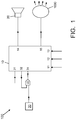
- FIG. 1 is a block diagram schematically illustrating the general design of a wake-up appliance according to the present invention, generally indicated by reference numeral 100.
- the wake-up appliance 100 comprises an alarm device 20, and a control device 10 having an alarm output 14 for controlling the alarm device 20.
- the control device has a user snooze input 11 and a user switch-off input 12, for instance implemented as pushbuttons or switches.
- the alarm device 20 is capable of generating an alarm signal, which, in the illustrative example, will be assumed to include a sound signal. It is noted however that alternatives are possible where the alarm device generates a visible signal (for instance TV or video) or a tactile signal.
- the alarm device 20 may include a buzzer, a beeper, a radio tuner, a music player, etc., or a combination thereof.
- the alarm device 20 may thus be a commonly known device, and a further explanation may be omitted here.
- the wake-up appliance 100 also includes a clock display, but this is not shown for the sake of simplicity.
- the control device 10 controls the operation of the alarm device 20.
- the control device 10 has an alarm time setting input 31 for allowing the user to input an alarm time.
- the appliance 100 includes clock means 30 for providing a signal that represents the actual time, and a comparator 33 for comparing the actual time with the alarm time set by the user, which alarm time is provided by the control device 10 at an output 32.
- the comparator 33 provides a comparator output signal indicating the comparison result, which is received at an input 34 of the control device 10.
- the clock 30, comparator 33 and controller 10 are shown as separate units, and the alarm time is input into the controller 10. However, it is also possible that the alarm time is input into the clock 30. It is further possible that the comparator 33 is integrated with the clock 30, or that the comparator 33 is integrated with the controller 10. It is even possible that the functions of clock, comparator and controller are performed by a common integrated device. The only relevant issue is that the control device 10 is provided with means to indicate when the actual time is equal to the alarm time set by the user.
- the control device 10 makes a transition to an alarm state and activates the alarm device 20.
- the control device 10 switches off the alarm device 20 and the appliance returns to its stand-by state: the alarm device 20 remains in its off state until the next time that the actual time becomes equal to the alarm time, for instance the next day.
- the control device 10 when the control device 10 is in the alarm state, the user may also actuate the snooze input 11. In response, the control device 10 will switch off the alarm device 20 and make a transition to the snooze state. In this snooze state, the control device 10 waits for a predefined amount of time of for instance 9 minutes, and then makes a transition to the alarm state again, activating the alarm device 20 again. The above may be repeated until finally the user actuates the switch-off input 12, causing the control device 10, in response, to switch off the alarm device 20 and return to the stand-by state.
- Wake-up appliances as described hereinabove are known per se.
- the alarm device 20 is not switched off entirely in the snooze state. For instance, it is possible that the output signal is reduced (dimmed), but will be switched to full power at the end of the snooze state; this will be particularly useful if the output signal is music. It is also possible that the alarm device produces a beep signal as well as music, and that, in the snooze state, the beep signal is suppressed but the music continues to play.
- the wake-up appliance 100 of the present invention also comprises a light-generating device 1000, capable of generating at least blue light.
- the control device 10 has a light control output 15 for controlling the light-generating device 1000.
- the control device 10 further may have a second switch-off input 13, as shown.
- control device 10 in response to the user's actuation of the snooze input 11: the control device 10 will control the light-generating device 1000 such as to increase the intensity of the blue light output.
- the blue range of the light spectrum will be considered to be the wavelength range from 430 to 490 nm.
- Blue light will be considered to be light having a wavelength within this blue range.
- Preferred blue light has a wavelength in the range from 460 to 480 nm.
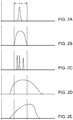
- the phrase "at least blue light” is used to indicate that the spectrum of the output light of the light-generating device 1000 has at least one non-zero spectral portion within the blue range. It is not necessary that the spectrum of the output light covers the entire blue range: the output light spectrum may include portions where the intensity is zero within the blue range.
- the horizontal axis represents wavelength
- the vertical axis represents intensity (spectral output power).
- the light-generating device 1000 does not have any spectral output outside the blue range, so that 100% of the light output is within the blue range.
- a light-generating device 1000 will be indicated as a "blue only” device, and its overall output light will be indicated as “blue”.
- the spectral intensity is non-zero in only one contiguous spectral range, i.e. the spectrum contains only one spectral peak. It is possible that such a peak is narrow with respect to the blue range, as illustrated in figure 2A . It is alternatively possible that such a peak has a width comparable to the width of the blue range, as illustrated in figure 2B .
- the spectral intensity is non-zero in two or more spectral sub-ranges, i.e. the spectrum contains multiple spectral peaks, as illustrated in figure 2C .
- Such peaks may or may not be equidistant, and may or may not be of the same height.
- the light-generating device 1000 does have a spectral output outside the blue range, so that the integrated spectral intensity of the light-generating device 1000 within the blue range (which will hereinafter also be indicated as blue intensity) is less than 100% of the overall integrated intensity of said device.
- the blue output power is higher than 50% of the overall output power, the light-generating device 1000 will be indicated as a "mainly blue” device, and its overall output light will be indicated as "mainly blue”.
- the spectral output may be as indicated above, while additionally there is spectral output outside the blue range. This spectral output outside the blue range may for instance comprise one or more narrow and/or wide peaks, a continuum, etc.
- the spectral intensity is non-zero in at least one relatively wide contiguous spectral range comprising at least part of the blue range or even comprising the entire blue range, as illustrated in figure 2D . It is even possible that the highest intensity value is located at a wavelength outside the blue range, as illustrated in figure 2E .
- the spectral intensity does not need to be constant within the blue range: in the case where a spectrum, or a portion thereof, has a more or less Gaussian profile, it is possible to define a central wavelength where the highest intensity value is reached. Preferably, this central wavelength lies within the blue range. It is also possible to define the width of the light spectrum as the width measured at 50% of the peak height: preferably, this width of the light spectrum lies within the blue range.
- Figure 1 schematically illustrates a light-generating device 1000 that comprises just one light source 50.
- an entity will be indicated as a separate light source if it can be controlled independently by the control device 10.
- Figure 3 shows that the control device 10 has one light source control output 15 for controlling said one light source 50.
- the control device 10 can only switch on or off the light source 50 as a whole, or increase or decrease the light output intensity of the light source 50 as a whole, but the spectrum of the output light will remain substantially constant.
- the light source 50 itself may comprise one or more light-generating elements 51, which may be mutually identical so that they have the same output spectrum, but even this is not essential.
- the light source 50 may also comprise just one light-generating element 51.
- the type of light-generating element 51 is not essential, but preferably the light-generating element 51 is implemented as an LED.
- a suitable LED, suitable for being used as light-generating element 51 in light source 50, is referred to as type 599LB7C, which is commercially available from the company Hebei International Trading (Shanghai) Co., Ltd. of Shanghai, China.
- the light-generating element 51 may be implemented as an OLED, a fluorescent lamp, a discharge lamp, etc.
- LEDs are typically driven by an electronic circuit indicated as a driver. In figure 3 , such a driver is not shown separately: it is considered to be included in the control device 10.
- the operation is as follows.
- the control device 10 When the user actuates the snooze input 11 for the first time, the control device 10 will make a transition to the snooze state and switch on the light source 50, or, if the light source 50 was already on, the control device 10 will increase the output power of the light source 50. Later, when the user actuates the snooze input 11 again, the control device 10 will again increase the light output of the light source 50.
- the present invention comes to expression even if the control device 10 increases the light output of the light-generating element 50 in response to only one of the user's snooze input actions, but it is preferred that the control device 10 increases the light output each time the user actuates the user snooze input 11, until, eventually, a maximum light output level is reached. It is further noted that the amount of light increase may differ after different snooze input actions.
- control device 10 may also switch off the light-generating device 1000. However, it is also possible that the control device 10 switches off the light-generating device 1000 in response to the user actuating the second switch-off input 13.
- the manner in which the blue light output intensity is increased in response to the user actuating the snooze input 11 may be implemented in several ways. It is possible that the blue light output intensity is increased step-wise from the current level to a new level, and then maintained constant until the alarm goes off. It is also possible that the blue light output intensity is increased gradually from the current level to a new level, and then maintained constant until the alarm goes off. It is also possible that the blue light output intensity is increased gradually, continuously, until the alarm goes off. Combinations of the above possibilities are also possible.
- control device 10 may effect the increase in blue light output immediately upon performing the transition to the snooze state, but also later during the snooze state, or both.
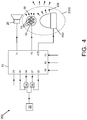
- FIG 4 is a block diagram schematically illustrating a first embodiment configuration of a wake-up appliance according to the present invention, generally indicated by reference numeral 200.
- the wake-up appliance 200 again comprises an alarm device 20, a light-generating device now indicated by reference numeral 2000, and a control device 10 for controlling the alarm device 20 and the light-generating device 2000.
- the control device again has a user snooze input 11, a user switch-off input 12 for switching off the alarm, and a second user switch-off input 13 for switching off the light-generating device 2000.
- the alarm device 20 may be identical to the alarm device described with reference to figures 1 and 3 , and the operation of the control device 10 with respect to the alarm device 20 may also be identical to the operation described with reference to figures 1 and 3 , so the description thereof need not be repeated here.
- the light-generating device 2000 comprises said one light source 50 described above, and additionally comprises at least one additional light source 450.
- the two light sources 50 and 450 are separate, meaning that they can be controlled by the control device 10 independently: the control device 10 has a first light source control output 15 for controlling the first light source 50 and a second light source control output 415 for controlling the second light source 450.
- the first light source 50 is identical to the one described hereinabove, so its description does not need to be repeated.
- the second light source 450 may consist of one light-generating element or a plurality of light-generating elements.
- the second light source 450 is a wake-up lamp. It is noted that, as far as structural design is concerned, it is possible that the two light sources 50 and 450 are physically separate, but it is also possible that they are mounted in a common housing so that, instead of perceiving two spatially separated light sources, a user only perceives the overall output light of the light-generating device 2000, i.e. the mix of output light from the first light source 50 and output light from the second light source 450, as originating from one source. It is even possible that the first light source 50 is mounted within a housing of the second light source 450.
- a wake-up lamp may comprise one or more light generating elements, for instance LED(s), fluorescent lamp(s), etc.
- the control device 10 controls the wake-up light 130 such as to slowly increase its light output from a minimum level to a maximum level, for instance from 0 to 100%. Typically, the control device 10 starts doing so before the alarm device 20 goes off.
- Figure 5A is a graph illustrating the possible timing of a wake-up lamp with a snooze function in general. The user has set the alarm at time tA. The control device 10 switches the alarm device 20 on at time tA, and switches it off again when the user actuates the snooze input 11 at time ts1.
- the control device 10 switches the alarm device 20 on again at time tA2, and switches it off again when the user actuates the snooze input 11 at time ts2. This is repeated at times tA3 and ts3, and may be repeated many times more. Curves 21, 22, 23 indicate the operative state of the alarm device 20.
- the user actuates the first switch-off input 12 at time ts3, so that the control device 10 switches back to the stand-by state, and actuates the second switch-off input 13 slightly later.
- Curve 459 indicates the light output of the wake-up lamp 450, and illustrates that the control device 10 has switched on the wake-up lamp 450 at a time tWUL, earlier than the alarm time tA, and that its light output gradually rises from zero.
- the figure shows a linear relationship between light output and time, but that is not essential.
- This figure also shows that the light output of the wake-up lamp 450 reaches its maximum around time tA, which is preferred yet not essential.
- the figure also shows that the wake-up lamp 450 is switched off in response to the user actuating the second switch-off input 13.
- the system may include a second comparator 36, receiving a signal indicating actual time from the clock 30, and receiving a signal from the control device 10 indicating time tWUL, which signal is provided by the control device at an output 35, and the output signal from this second comparator 36 is received by the control device 10 at an input 37.
- this second comparator 36 it may for instance be integrated in the control device 10.
- Figure 5A shows the normal operation in the absence of the snooze-response according to the present invention.
- Figure 5B is a graph comparable to figure 5A , illustrating the operation of the device 200 according to the present invention.
- Curve 59 indicates the light output of the first light source 50. It can clearly be seen that, in the snooze state, the control device 10 always increases this light output. This can be done for instance stepwise (shown at time ts1) or gradually (shown between time ts2 and ta3). Increases in light output (whether stepwise or gradually) may be of the same size, but that is not essential.
- the control of the wake-up lamp 450 may be unamended as compared to that of figure 5A .
- the control is the same as described earlier: in response to the user's snooze actions, i.e. at the beginning of or during the snooze state, the output power of the first light source 50 is increased, resulting in an increase of the amount of blue light generated.
- the advantageous effect is found in the fact that blue light, especially light within the wavelength range of 430 nm to 490 nm, and particularly light within the wavelength range of 460 nm to 480 nm, appears to have a relatively high alerting effect on the human physiology.
- the second controllable light source 450 whether this is a wake-up lamp or not, further possibilities are available for the control device 10.
- the light output from the second controllable light source 450 will typically have a colour point different from that of the first controllable light source 50.
- the control device 10 may adapt its control of the second controllable light source 450 to compensate for this.
- the control device 10 adapts its control of the second controllable light source 450 to reduce the intensity of the output light of the second controllable light source 450 simultaneously with and to the same extent as any increase in the output power of the first light source 50, so that, in the perception of the user, the overall light output (perceived brightness) of the light-generating device 2000 as a whole remains substantially constant.
- Such operation is illustrated in figure 5B .
- the control device 10 controls the light-generating device 2000 as a whole such that the overall light output brightness follows a predefined function of time (not necessarily remaining constant), with increases in the blue light output being compensated by decreases in the light output of the second controllable light source 450. The overall result will nevertheless be an increase of the amount of blue light.
- the control device 10 adapts its control of the second controllable light source 450 to change the colour point of the output light of the second controllable light source 450 simultaneously with any increase of the output power of the first light source 50, in such a way that, in the perception of the user, the colour point of the light-generating device 2000 as a whole remains substantially constant.
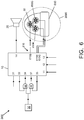
- FIG. 6 is a block diagram schematically illustrating a second embodiment configuration of a wake-up appliance according to the present invention, generally indicated by reference numeral 300.
- the wake-up appliance 300 again comprises an alarm device 20, a light-generating device now indicated by reference numeral 3000, and a control device 10 for controlling the alarm device 20 and the light-generating device 3000.
- the control device again has a user snooze input 11, a user switch-off input 12 for switching off the alarm, and a second user switch-off input 13 for switching off the light-generating device 3000.
- the alarm device 20 may be identical to the alarm device described with reference to figures 1 and 3 , and the operation of the control device 10 with respect to the alarm device 20 may also be identical to the operation described with reference to figures 1 and 3 , so the description thereof need not be repeated here.
- the light-generating device 3000 is implemented as a wake-up lamp 650 comprising a plurality of light sources 50, 650R, 650G, of mutually different colour, including at least one light source 50 generating blue light, or mainly blue light, or partially blue light.
- the light source 50 may be identical to the one described hereinabove; the other light sources may for instance be light sources for generating mainly or exclusively red (R) and green (G) light, respectively, but other colours are also possible.
- the wake-up lamp 650 may have just one, or three or more additional light sources. Suitable light sources may include fluorescent lamps, LEDs, etc.
- the light-generating device 3000 is of a type having a controllable output colour, which is effected by individually controlling the light output of the individual light sources.
- a control output 615 for the wake-up lamp 650 is subdivided into three separate control outputs 615B, 615R, 615G, i.e. one control output for said one light source 50, one separate control output 615R for the light source 650R and one separate control output 615G for the light source 650G.
- the control device 10 can set the overall colour of the overall output light of the wake-up lamp 3000 to be almost white, or reddish, or yellowish, or blueish, as desired.
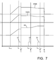
- Figure 7 is a graph comparable to figure 5B , illustrating the operation of this embodiment.
- the control device 10 When operating in accordance with the present invention, the control device 10 will first generate its output signals such as to slowly increase the light output of all light sources 50, 650R, 650G as from time tWUL, in order to obtain the wake-up lamp functionality. After the alarm time tA, in the snooze states, the control device 10 will boost the light output of the blue light source 50 (stepwise, or gradually, or continuously), in the manner described in the above.
- control device 10 may keep the light output of the other light sources 650R, 650G of the wake-up lamp 650 constant, or may adapt the control of the other light sources 650R, 650G of the wake-up lamp 650 such as to keep constant the intensity or the colour point of the overall output light of the wake-up lamp 3000.
- the present invention provides a wake-up appliance 100; 200; 300 comprising an alarm device 20 generating an alarm signal, a control device (10) controlling the alarm device, and at least one controllable light-generating device 1000; 2000; 3000 controlled by the control device.
- control device When the control device finds that an actual time becomes equal to a predetermined alarm time, it activates the alarm device.When the control device receives a user input signal at a snooze input, it stops the alarm signal and increases the intensity of at least a portion of the light generated in a blue range of the light spectrum.
- the invention has been described for a specific embodiment where the relative spectral intensity in the blue region is increased at the moment when the user actuates the snooze button, and otherwise remains constant. More generally, the relative blue intensity may also increase during the snooze intervals. However, it is also possible that, after the user has actuated the snooze button, the control device 10 waits for a predetermined delay time before increasing the blue light output.
Landscapes
- Physics & Mathematics (AREA)
- General Physics & Mathematics (AREA)
- Electric Clocks (AREA)
- Circuit Arrangement For Electric Light Sources In General (AREA)
- Electromechanical Clocks (AREA)
Claims (11)
- Appareil de réveil (200 ; 300) comprenant :un dispositif d'alarme (20) destiné à la génération d'un signal d'alarme ;un dispositif de commande (10) destiné à la commande du fonctionnement du dispositif d'alarme, le dispositif de commande comportant une entrée de répétition (11) destinée à la réception d'un signal d'entrée utilisateur ;dans lequel le dispositif de commande est apte au fonctionnement dans un état d'alarme et dans un état de répétition ;dans lequel le dispositif de commande est conçu pour activer, lorsqu'il fonctionne dans l'état d'alarme, le dispositif d'alarme de manière à produire le signal d'alarme ;dans lequel le dispositif de commande est conçu pour effectuer une transition, en réponse à la réception d'un signal d'entrée utilisateur au niveau de son entrée de répétition, vers l'état de répétition et pour commander le dispositif d'alarme de manière à arrêter le signal d'alarme ou à réduire l'intensité du signal du signal d'alarme, puis pour attendre un intervalle de répétition prédéterminé, puis pour effectuer une transition de retour vers l'état d'alarme et pour réactiver le dispositif d'alarme ;dans lequel ledit appareil comprend en outre au moins un dispositif générateur de lumière (2000 ; 3000) commandable commandé par le dispositif de commande, dans lequel ledit dispositif générateur de lumière est apte à la génération de la lumière dans au moins une plage de bleu du spectre lumineux ;et dans lequel le dispositif de commande est conçu pour commander, en réponse à la réception du signal d'entrée utilisateur au niveau de son entrée de répétition, le dispositif générateur de lumière de manière à augmenter l'intensité lumineuse dans au moins une partie de ladite plage de bleu ;dans lequel ledit dispositif de génération de lumière (2000 ; 3000) comprend au moins une première source lumineuse (50) générant une lumière de sortie présentant un spectre, lequel est non nul dans au moins une sous-plage dans ladite plage de bleu du spectre lumineux ;et dans lequel le dispositif de commande est conçu pour augmenter, en réponse à la réception du signal d'entrée utilisateur au niveau de son entrée de répétition, l'intensité lumineuse de ladite première source lumineuse (50) ;dans lequel ledit dispositif de génération de lumière (2000 ; 3000) comprend en outre au moins une seconde source lumineuse (450 ; 650R, 650G) commandée par le dispositif de commande (10) indépendamment de ladite première source lumineuse (50).
- Appareil de réveil selon la revendication 1, dans lequel ladite plage de bleu du spectre lumineux se situe dans une plage spectrale comprise entre 430 et 490 nm.
- Appareil de réveil selon la revendication 1, dans lequel ladite plage de bleu du spectre lumineux se situe dans une plage spectrale comprise entre 460 et 480 nm.
- Appareil de réveil selon la revendication 1, dans lequel la lumière de sortie de ladite première source lumineuse (50) présente un spectre, lequel est nul pour toutes les longueurs d'onde en dehors de ladite plage de bleu du spectre lumineux.
- Appareil de réveil selon la revendication 1, dans laquelle la formule suivante s'applique :


Bl indiquant une longueur d'onde limite inférieure de la plage bleue,
Bu indiquant une longueur d'onde limite supérieure de la gamme bleue, et I(λ) indiquant l'intensité spectrale à la longueur d'onde λ, et
- Appareil de réveil selon la revendication 1, dans lequel ladite seconde source lumineuse (450) est mise en œuvre en tant qu'une lampe de réveil, dans lequel le dispositif de commande (10) est conçu pour commander la lampe de réveil de telle sorte que l'intensité lumineuse de la lampe de réveil commence à augmenter d'un niveau minimal à un niveau maximal avant que le dispositif de commande n'active le dispositif d'alarme (20) et de telle sorte que, chaque fois que l'intensité lumineuse de ladite première source lumineuse (50) est augmentée en réponse à la réception du signal d'entrée utilisateur au niveau de l'entrée de répétition, l'intensité lumineuse de la lampe de réveil est maintenue constante.
- Appareil de réveil selon la revendication 1, dans lequel le dispositif de commande (10) est conçu pour commander la seconde source lumineuse (450) et ladite première source lumineuse (50) en réponse à la réception du signal d'entrée utilisateur au niveau de l'entrée de répétition de telle sorte que l'intensité lumineuse de ladite première lumière la source (50) est augmentée, l'augmentation de la sortie de lumière de ladite première source lumineuse (50) étant compensée par une diminution de la sortie de lumière de la seconde source lumineuse (450) commandable de telle sorte que la luminosité globale de sortie de lumière suive une fonction prédéfinie du temps.
- Appareil de réveil selon la revendication 1, dans lequel le dispositif de commande (10) est conçu pour commander la seconde source lumineuse (450 ; 650R, 650G) pour réduire l'intensité lumineuse de sortie de la seconde source lumineuse (450 ; 650R, 650G) et pour augmenter simultanément l'intensité lumineuse de ladite première source lumineuse (50) de telle sorte que l'intensité globale perçue de toute la lumière émise par ledit dispositif générateur de lumière (2000) reste constante.
- Appareil de réveil selon la revendication 1, dans lequel ledit dispositif générateur de lumière (3000) est mis en œuvre en tant qu'une lampe de réveil et comprend ladite première source lumineuse (50) et ladite seconde source lumineuse (650R, 650G) commandées par le dispositif de commande (10) indépendamment de ladite première source lumineuse (50) et dans lequel le dispositif de commande (10) est conçu pour commander la lampe de réveil de telle sorte que l'intensité lumineuse de la lampe de réveil commence à augmenter d'un niveau minimal à un niveau maximal avant que le dispositif de commande n'active le dispositif d'alarme (20).
- Appareil de réveil selon la revendication 1, dans lequel le dispositif de commande est conçu pour augmenter progressivement l'intensité lumineuse de la lumière bleue et pour effectuer simultanément la transition vers l'état de répétition.
- Appareil de réveil selon la revendication 1, dans lequel le dispositif de commande est conçu pour toujours augmenter l'intensité lumineuse de la lumière bleue en réponse à chaque signal d'entrée utilisateur reçu au niveau de son entrée de répétition.
Priority Applications (1)
| Application Number | Priority Date | Filing Date | Title |
|---|---|---|---|
| EP12718378.8A EP2697694B1 (fr) | 2011-04-14 | 2012-04-05 | Appareil de réveil avec fonction répétition |
Applications Claiming Priority (3)
| Application Number | Priority Date | Filing Date | Title |
|---|---|---|---|
| EP11162369 | 2011-04-14 | ||
| EP12718378.8A EP2697694B1 (fr) | 2011-04-14 | 2012-04-05 | Appareil de réveil avec fonction répétition |
| PCT/IB2012/051679 WO2012140549A1 (fr) | 2011-04-14 | 2012-04-05 | Appareil de réveil avec fonction répétition |
Publications (2)
| Publication Number | Publication Date |
|---|---|
| EP2697694A1 EP2697694A1 (fr) | 2014-02-19 |
| EP2697694B1 true EP2697694B1 (fr) | 2021-06-16 |
Family
ID=46025818
Family Applications (1)
| Application Number | Title | Priority Date | Filing Date |
|---|---|---|---|
| EP12718378.8A Active EP2697694B1 (fr) | 2011-04-14 | 2012-04-05 | Appareil de réveil avec fonction répétition |
Country Status (7)
| Country | Link |
|---|---|
| US (1) | US9298169B2 (fr) |
| EP (1) | EP2697694B1 (fr) |
| JP (1) | JP6084602B2 (fr) |
| CN (1) | CN103492961B (fr) |
| BR (1) | BR112013026013B1 (fr) |
| RU (1) | RU2592773C2 (fr) |
| WO (1) | WO2012140549A1 (fr) |
Families Citing this family (3)
| Publication number | Priority date | Publication date | Assignee | Title |
|---|---|---|---|---|
| KR101594036B1 (ko) * | 2012-09-26 | 2016-02-15 | 고재천 | 램프 연동 알람시계 및 그에 의한 램프 동작 제어 방법 |
| DE102015102262A1 (de) * | 2015-02-18 | 2016-08-18 | Martin Staud GmbH | Vorrichtung zum Steuern einer Weck-Einschlaf-Vorrichtung |
| CN109392228B (zh) * | 2017-08-10 | 2021-12-28 | 松下知识产权经营株式会社 | 照明系统 |
Citations (2)
| Publication number | Priority date | Publication date | Assignee | Title |
|---|---|---|---|---|
| EP1959320A1 (fr) * | 2005-11-25 | 2008-08-20 | Matsushita Electric Works, Ltd. | Dispositif de reveil |
| WO2009077941A1 (fr) * | 2007-12-14 | 2009-06-25 | Koninklijke Philips Electronics N.V. | Système de réveil et procédé pour réveiller une personne à l'aide de la lumière |
Family Cites Families (23)
| Publication number | Priority date | Publication date | Assignee | Title |
|---|---|---|---|---|
| US5079682A (en) * | 1987-08-07 | 1992-01-07 | Roberts Seth D | Arising aid |
| US6236622B1 (en) * | 1999-05-01 | 2001-05-22 | Verilux, Inc. | Lamp and alarm clock with gradually increasing light or sounds |
| US6888779B2 (en) * | 2001-11-20 | 2005-05-03 | Pulsar Informatics, Inc. | Method and apparatus for a waking control system |
| US7722212B2 (en) * | 2002-06-15 | 2010-05-25 | Searfoss Robert L | Nightlight for phototherapy |
| US20050012622A1 (en) * | 2003-05-19 | 2005-01-20 | Sutton William R. | Monitoring and control of sleep cycles |
| WO2005084538A1 (fr) * | 2004-02-27 | 2005-09-15 | Axon Sleep Research Laboratories, Inc. | Dispositif et methode de prediction de la phase de sommeil d'un utilisateur |
| CN1737706A (zh) * | 2004-08-18 | 2006-02-22 | 周良 | 一种通过光线变化将人定时唤醒的装置 |
| GB2422448B (en) * | 2005-01-19 | 2009-03-11 | Outside In | Dawn simulator |
| WO2006087723A2 (fr) * | 2005-02-18 | 2006-08-24 | Mata Temed Ltd. | Dispositif et procede de luminotherapie multi-niveau |
| GB2434260A (en) * | 2006-01-11 | 2007-07-18 | Outside In | Phototherapy lights |
| US7280439B1 (en) * | 2006-01-23 | 2007-10-09 | Daniel Edward Shaddox | Sunlight simulating microprocessor alarm clock |
| CN100504670C (zh) * | 2006-03-08 | 2009-06-24 | 同济大学 | 一种“自然醒”闹钟及其实施方法 |
| JP2007294143A (ja) * | 2006-04-21 | 2007-11-08 | Daikin Ind Ltd | 照明装置及び該照明装置を備えたベッド |
| JP2008139031A (ja) * | 2006-11-30 | 2008-06-19 | Matsushita Electric Works Ltd | 目覚まし照明装置 |
| CN101646474A (zh) * | 2007-03-09 | 2010-02-10 | 皇家飞利浦电子股份有限公司 | 用于活力激励的照明系统 |
| WO2008156593A2 (fr) * | 2007-06-20 | 2008-12-24 | Eveready Battery Company, Inc. | Dispositif d'éclairage portable équipé d'une commande de lumière pouvant être sélectionnée par l'utilisateur |
| GB2453359A (en) * | 2007-10-04 | 2009-04-08 | Gullwing Ltd | LED light box with dawn and dusk simulation |
| JP5535940B2 (ja) | 2008-01-17 | 2014-07-02 | コーニンクレッカ フィリップス エヌ ヴェ | 照明デバイス |
| EP2120117A1 (fr) * | 2008-05-13 | 2009-11-18 | Koninklijke Philips Electronics N.V. | Appareil pour réveiller un utilisateur |
| WO2010035200A1 (fr) | 2008-09-26 | 2010-04-01 | Koninklijke Philips Electronics, N.V. | Appareil et techniques de simulation de cycles de lumière naturelle |
| GB2468277A (en) | 2009-02-25 | 2010-09-08 | Tsai-Ying Wu | A perfume-dispensing, light-intensity-increasing, and music- playing alarm clock |
| US8284631B2 (en) * | 2009-12-14 | 2012-10-09 | Tirid Tech Co., Ltd. | Multimedia projection alarm clock with integrated illumination |
| US20130163394A1 (en) * | 2011-12-23 | 2013-06-27 | Leonor F. Loree, IV | Easy Wake System and Method |
-
2012
- 2012-04-05 WO PCT/IB2012/051679 patent/WO2012140549A1/fr active Application Filing
- 2012-04-05 EP EP12718378.8A patent/EP2697694B1/fr active Active
- 2012-04-05 BR BR112013026013-0A patent/BR112013026013B1/pt active IP Right Grant
- 2012-04-05 RU RU2013150576/12A patent/RU2592773C2/ru active
- 2012-04-05 US US14/110,725 patent/US9298169B2/en active Active
- 2012-04-05 CN CN201280018304.XA patent/CN103492961B/zh active Active
- 2012-04-05 JP JP2014504420A patent/JP6084602B2/ja active Active
Patent Citations (2)
| Publication number | Priority date | Publication date | Assignee | Title |
|---|---|---|---|---|
| EP1959320A1 (fr) * | 2005-11-25 | 2008-08-20 | Matsushita Electric Works, Ltd. | Dispositif de reveil |
| WO2009077941A1 (fr) * | 2007-12-14 | 2009-06-25 | Koninklijke Philips Electronics N.V. | Système de réveil et procédé pour réveiller une personne à l'aide de la lumière |
Also Published As
| Publication number | Publication date |
|---|---|
| RU2013150576A (ru) | 2015-05-20 |
| BR112013026013A2 (pt) | 2016-12-20 |
| EP2697694A1 (fr) | 2014-02-19 |
| JP6084602B2 (ja) | 2017-02-22 |
| BR112013026013B1 (pt) | 2021-06-08 |
| CN103492961B (zh) | 2016-09-28 |
| CN103492961A (zh) | 2014-01-01 |
| JP2014512010A (ja) | 2014-05-19 |
| US20140036642A1 (en) | 2014-02-06 |
| US9298169B2 (en) | 2016-03-29 |
| RU2592773C2 (ru) | 2016-07-27 |
| WO2012140549A1 (fr) | 2012-10-18 |
Similar Documents
| Publication | Publication Date | Title |
|---|---|---|
| EP2953428B1 (fr) | Techniques de commande d'éclairage tenant compte des changements dans la sensibilité de l' oeil | |
| EP2608639A1 (fr) | Dispositif d'éclairage | |
| JP2011233291A (ja) | 照明装置 | |
| JP2010238407A (ja) | 照明装置及び照明システム | |
| EP2697694B1 (fr) | Appareil de réveil avec fonction répétition | |
| JP2018527708A (ja) | スリーピーライト | |
| EP2745636B1 (fr) | Luminaire a intensite variable presentant un changement de couleur lors de l'obscurcissement | |
| WO2010035200A1 (fr) | Appareil et techniques de simulation de cycles de lumière naturelle | |
| US11737182B1 (en) | Systems and methods for changing a color temperature of a light | |
| US9986609B2 (en) | Lighting apparatus and lighting system | |
| JP2017159803A (ja) | 照明システム及び移動体 | |
| TWI757504B (zh) | 照明系統 | |
| KR20160006459A (ko) | 다기능 베개장치 | |
| GB2422447A (en) | Dawn simulator alarm clock | |
| JP2011165578A (ja) | 照明装置 | |
| JP5645200B2 (ja) | 照明装置 | |
| JP2006278051A (ja) | 照明制御装置および照明システム | |
| JP6292791B2 (ja) | 照明装置 | |
| JP6405511B1 (ja) | バックライト装置及びこれを備えた液晶ディスプレイ装置 | |
| GB2422448A (en) | Dawn simulator | |
| JP2011082107A (ja) | 照明調光装置 | |
| KR200335069Y1 (ko) | 전기밥솥의 예약취사회로. | |
| KR20150075518A (ko) | 조도조절이 가능한 조명등 | |
| JP3179621U (ja) | 光源設備(lightsourceapparatus) | |
| JP2012155901A (ja) | 照明器具 |
Legal Events
| Date | Code | Title | Description |
|---|---|---|---|
| PUAI | Public reference made under article 153(3) epc to a published international application that has entered the european phase |
Free format text: ORIGINAL CODE: 0009012 |
|
| 17P | Request for examination filed |
Effective date: 20131114 |
|
| AK | Designated contracting states |
Kind code of ref document: A1 Designated state(s): AL AT BE BG CH CY CZ DE DK EE ES FI FR GB GR HR HU IE IS IT LI LT LU LV MC MK MT NL NO PL PT RO RS SE SI SK SM TR |
|
| 17Q | First examination report despatched |
Effective date: 20140211 |
|
| DAX | Request for extension of the european patent (deleted) | ||
| STAA | Information on the status of an ep patent application or granted ep patent |
Free format text: STATUS: EXAMINATION IS IN PROGRESS |
|
| RAP1 | Party data changed (applicant data changed or rights of an application transferred) |
Owner name: KONINKLIJKE PHILIPS N.V. |
|
| GRAP | Despatch of communication of intention to grant a patent |
Free format text: ORIGINAL CODE: EPIDOSNIGR1 |
|
| STAA | Information on the status of an ep patent application or granted ep patent |
Free format text: STATUS: GRANT OF PATENT IS INTENDED |
|
| INTG | Intention to grant announced |
Effective date: 20210118 |
|
| GRAS | Grant fee paid |
Free format text: ORIGINAL CODE: EPIDOSNIGR3 |
|
| GRAA | (expected) grant |
Free format text: ORIGINAL CODE: 0009210 |
|
| STAA | Information on the status of an ep patent application or granted ep patent |
Free format text: STATUS: THE PATENT HAS BEEN GRANTED |
|
| AK | Designated contracting states |
Kind code of ref document: B1 Designated state(s): AL AT BE BG CH CY CZ DE DK EE ES FI FR GB GR HR HU IE IS IT LI LT LU LV MC MK MT NL NO PL PT RO RS SE SI SK SM TR |
|
| REG | Reference to a national code |
Ref country code: GB Ref legal event code: FG4D |
|
| REG | Reference to a national code |
Ref country code: CH Ref legal event code: EP |
|
| REG | Reference to a national code |
Ref country code: DE Ref legal event code: R096 Ref document number: 602012075847 Country of ref document: DE |
|
| REG | Reference to a national code |
Ref country code: AT Ref legal event code: REF Ref document number: 1402847 Country of ref document: AT Kind code of ref document: T Effective date: 20210715 |
|
| REG | Reference to a national code |
Ref country code: IE Ref legal event code: FG4D |
|
| REG | Reference to a national code |
Ref country code: LT Ref legal event code: MG9D |
|
| PG25 | Lapsed in a contracting state [announced via postgrant information from national office to epo] |
Ref country code: LT Free format text: LAPSE BECAUSE OF FAILURE TO SUBMIT A TRANSLATION OF THE DESCRIPTION OR TO PAY THE FEE WITHIN THE PRESCRIBED TIME-LIMIT Effective date: 20210616 Ref country code: FI Free format text: LAPSE BECAUSE OF FAILURE TO SUBMIT A TRANSLATION OF THE DESCRIPTION OR TO PAY THE FEE WITHIN THE PRESCRIBED TIME-LIMIT Effective date: 20210616 Ref country code: BG Free format text: LAPSE BECAUSE OF FAILURE TO SUBMIT A TRANSLATION OF THE DESCRIPTION OR TO PAY THE FEE WITHIN THE PRESCRIBED TIME-LIMIT Effective date: 20210916 Ref country code: HR Free format text: LAPSE BECAUSE OF FAILURE TO SUBMIT A TRANSLATION OF THE DESCRIPTION OR TO PAY THE FEE WITHIN THE PRESCRIBED TIME-LIMIT Effective date: 20210616 |
|
| REG | Reference to a national code |
Ref country code: AT Ref legal event code: MK05 Ref document number: 1402847 Country of ref document: AT Kind code of ref document: T Effective date: 20210616 |
|
| REG | Reference to a national code |
Ref country code: NL Ref legal event code: MP Effective date: 20210616 |
|
| PG25 | Lapsed in a contracting state [announced via postgrant information from national office to epo] |
Ref country code: LV Free format text: LAPSE BECAUSE OF FAILURE TO SUBMIT A TRANSLATION OF THE DESCRIPTION OR TO PAY THE FEE WITHIN THE PRESCRIBED TIME-LIMIT Effective date: 20210616 Ref country code: GR Free format text: LAPSE BECAUSE OF FAILURE TO SUBMIT A TRANSLATION OF THE DESCRIPTION OR TO PAY THE FEE WITHIN THE PRESCRIBED TIME-LIMIT Effective date: 20210917 Ref country code: SE Free format text: LAPSE BECAUSE OF FAILURE TO SUBMIT A TRANSLATION OF THE DESCRIPTION OR TO PAY THE FEE WITHIN THE PRESCRIBED TIME-LIMIT Effective date: 20210616 Ref country code: RS Free format text: LAPSE BECAUSE OF FAILURE TO SUBMIT A TRANSLATION OF THE DESCRIPTION OR TO PAY THE FEE WITHIN THE PRESCRIBED TIME-LIMIT Effective date: 20210616 Ref country code: NO Free format text: LAPSE BECAUSE OF FAILURE TO SUBMIT A TRANSLATION OF THE DESCRIPTION OR TO PAY THE FEE WITHIN THE PRESCRIBED TIME-LIMIT Effective date: 20210916 |
|
| PG25 | Lapsed in a contracting state [announced via postgrant information from national office to epo] |
Ref country code: PT Free format text: LAPSE BECAUSE OF FAILURE TO SUBMIT A TRANSLATION OF THE DESCRIPTION OR TO PAY THE FEE WITHIN THE PRESCRIBED TIME-LIMIT Effective date: 20211018 Ref country code: NL Free format text: LAPSE BECAUSE OF FAILURE TO SUBMIT A TRANSLATION OF THE DESCRIPTION OR TO PAY THE FEE WITHIN THE PRESCRIBED TIME-LIMIT Effective date: 20210616 Ref country code: RO Free format text: LAPSE BECAUSE OF FAILURE TO SUBMIT A TRANSLATION OF THE DESCRIPTION OR TO PAY THE FEE WITHIN THE PRESCRIBED TIME-LIMIT Effective date: 20210616 Ref country code: ES Free format text: LAPSE BECAUSE OF FAILURE TO SUBMIT A TRANSLATION OF THE DESCRIPTION OR TO PAY THE FEE WITHIN THE PRESCRIBED TIME-LIMIT Effective date: 20210616 Ref country code: AT Free format text: LAPSE BECAUSE OF FAILURE TO SUBMIT A TRANSLATION OF THE DESCRIPTION OR TO PAY THE FEE WITHIN THE PRESCRIBED TIME-LIMIT Effective date: 20210616 Ref country code: SK Free format text: LAPSE BECAUSE OF FAILURE TO SUBMIT A TRANSLATION OF THE DESCRIPTION OR TO PAY THE FEE WITHIN THE PRESCRIBED TIME-LIMIT Effective date: 20210616 Ref country code: SM Free format text: LAPSE BECAUSE OF FAILURE TO SUBMIT A TRANSLATION OF THE DESCRIPTION OR TO PAY THE FEE WITHIN THE PRESCRIBED TIME-LIMIT Effective date: 20210616 Ref country code: CZ Free format text: LAPSE BECAUSE OF FAILURE TO SUBMIT A TRANSLATION OF THE DESCRIPTION OR TO PAY THE FEE WITHIN THE PRESCRIBED TIME-LIMIT Effective date: 20210616 Ref country code: EE Free format text: LAPSE BECAUSE OF FAILURE TO SUBMIT A TRANSLATION OF THE DESCRIPTION OR TO PAY THE FEE WITHIN THE PRESCRIBED TIME-LIMIT Effective date: 20210616 |
|
| PG25 | Lapsed in a contracting state [announced via postgrant information from national office to epo] |
Ref country code: PL Free format text: LAPSE BECAUSE OF FAILURE TO SUBMIT A TRANSLATION OF THE DESCRIPTION OR TO PAY THE FEE WITHIN THE PRESCRIBED TIME-LIMIT Effective date: 20210616 |
|
| REG | Reference to a national code |
Ref country code: DE Ref legal event code: R097 Ref document number: 602012075847 Country of ref document: DE |
|
| PLBE | No opposition filed within time limit |
Free format text: ORIGINAL CODE: 0009261 |
|
| STAA | Information on the status of an ep patent application or granted ep patent |
Free format text: STATUS: NO OPPOSITION FILED WITHIN TIME LIMIT |
|
| PG25 | Lapsed in a contracting state [announced via postgrant information from national office to epo] |
Ref country code: DK Free format text: LAPSE BECAUSE OF FAILURE TO SUBMIT A TRANSLATION OF THE DESCRIPTION OR TO PAY THE FEE WITHIN THE PRESCRIBED TIME-LIMIT Effective date: 20210616 |
|
| 26N | No opposition filed |
Effective date: 20220317 |
|
| PG25 | Lapsed in a contracting state [announced via postgrant information from national office to epo] |
Ref country code: AL Free format text: LAPSE BECAUSE OF FAILURE TO SUBMIT A TRANSLATION OF THE DESCRIPTION OR TO PAY THE FEE WITHIN THE PRESCRIBED TIME-LIMIT Effective date: 20210616 |
|
| PG25 | Lapsed in a contracting state [announced via postgrant information from national office to epo] |
Ref country code: IT Free format text: LAPSE BECAUSE OF FAILURE TO SUBMIT A TRANSLATION OF THE DESCRIPTION OR TO PAY THE FEE WITHIN THE PRESCRIBED TIME-LIMIT Effective date: 20210616 |
|
| REG | Reference to a national code |
Ref country code: CH Ref legal event code: PL |
|
| GBPC | Gb: european patent ceased through non-payment of renewal fee |
Effective date: 20220405 |
|
| REG | Reference to a national code |
Ref country code: BE Ref legal event code: MM Effective date: 20220430 |
|
| PG25 | Lapsed in a contracting state [announced via postgrant information from national office to epo] |
Ref country code: MC Free format text: LAPSE BECAUSE OF FAILURE TO SUBMIT A TRANSLATION OF THE DESCRIPTION OR TO PAY THE FEE WITHIN THE PRESCRIBED TIME-LIMIT Effective date: 20210616 Ref country code: LU Free format text: LAPSE BECAUSE OF NON-PAYMENT OF DUE FEES Effective date: 20220405 Ref country code: LI Free format text: LAPSE BECAUSE OF NON-PAYMENT OF DUE FEES Effective date: 20220430 Ref country code: GB Free format text: LAPSE BECAUSE OF NON-PAYMENT OF DUE FEES Effective date: 20220405 Ref country code: FR Free format text: LAPSE BECAUSE OF NON-PAYMENT OF DUE FEES Effective date: 20220430 Ref country code: CH Free format text: LAPSE BECAUSE OF NON-PAYMENT OF DUE FEES Effective date: 20220430 |
|
| PG25 | Lapsed in a contracting state [announced via postgrant information from national office to epo] |
Ref country code: BE Free format text: LAPSE BECAUSE OF NON-PAYMENT OF DUE FEES Effective date: 20220430 |
|
| PG25 | Lapsed in a contracting state [announced via postgrant information from national office to epo] |
Ref country code: IE Free format text: LAPSE BECAUSE OF NON-PAYMENT OF DUE FEES Effective date: 20220405 |
|
| PGFP | Annual fee paid to national office [announced via postgrant information from national office to epo] |
Ref country code: DE Payment date: 20220628 Year of fee payment: 12 |
|
| PG25 | Lapsed in a contracting state [announced via postgrant information from national office to epo] |
Ref country code: HU Free format text: LAPSE BECAUSE OF FAILURE TO SUBMIT A TRANSLATION OF THE DESCRIPTION OR TO PAY THE FEE WITHIN THE PRESCRIBED TIME-LIMIT; INVALID AB INITIO Effective date: 20120405 |
|
| PG25 | Lapsed in a contracting state [announced via postgrant information from national office to epo] |
Ref country code: MK Free format text: LAPSE BECAUSE OF FAILURE TO SUBMIT A TRANSLATION OF THE DESCRIPTION OR TO PAY THE FEE WITHIN THE PRESCRIBED TIME-LIMIT Effective date: 20210616 Ref country code: CY Free format text: LAPSE BECAUSE OF FAILURE TO SUBMIT A TRANSLATION OF THE DESCRIPTION OR TO PAY THE FEE WITHIN THE PRESCRIBED TIME-LIMIT Effective date: 20210616 |