EP2696141B1 - Processing system and method for stabilizing livestock reclaimed ground by on-site underground combustion - Google Patents
Processing system and method for stabilizing livestock reclaimed ground by on-site underground combustion Download PDFInfo
- Publication number
- EP2696141B1 EP2696141B1 EP12768105.4A EP12768105A EP2696141B1 EP 2696141 B1 EP2696141 B1 EP 2696141B1 EP 12768105 A EP12768105 A EP 12768105A EP 2696141 B1 EP2696141 B1 EP 2696141B1
- Authority
- EP
- European Patent Office
- Prior art keywords
- heat
- combustion
- landfill
- carcasses
- livestock
- Prior art date
- Legal status (The legal status is an assumption and is not a legal conclusion. Google has not performed a legal analysis and makes no representation as to the accuracy of the status listed.)
- Not-in-force
Links
Images




Classifications
-
- F—MECHANICAL ENGINEERING; LIGHTING; HEATING; WEAPONS; BLASTING
- F23—COMBUSTION APPARATUS; COMBUSTION PROCESSES
- F23G—CREMATION FURNACES; CONSUMING WASTE PRODUCTS BY COMBUSTION
- F23G1/00—Furnaces for cremation of human or animal carcasses
-
- B—PERFORMING OPERATIONS; TRANSPORTING
- B09—DISPOSAL OF SOLID WASTE; RECLAMATION OF CONTAMINATED SOIL
- B09B—DISPOSAL OF SOLID WASTE NOT OTHERWISE PROVIDED FOR
- B09B3/00—Destroying solid waste or transforming solid waste into something useful or harmless
- B09B3/40—Destroying solid waste or transforming solid waste into something useful or harmless involving thermal treatment, e.g. evaporation
-
- B—PERFORMING OPERATIONS; TRANSPORTING
- B09—DISPOSAL OF SOLID WASTE; RECLAMATION OF CONTAMINATED SOIL
- B09B—DISPOSAL OF SOLID WASTE NOT OTHERWISE PROVIDED FOR
- B09B1/00—Dumping solid waste
-
- B—PERFORMING OPERATIONS; TRANSPORTING
- B09—DISPOSAL OF SOLID WASTE; RECLAMATION OF CONTAMINATED SOIL
- B09B—DISPOSAL OF SOLID WASTE NOT OTHERWISE PROVIDED FOR
- B09B5/00—Operations not covered by a single other subclass or by a single other group in this subclass
-
- C—CHEMISTRY; METALLURGY
- C05—FERTILISERS; MANUFACTURE THEREOF
- C05F—ORGANIC FERTILISERS NOT COVERED BY SUBCLASSES C05B, C05C, e.g. FERTILISERS FROM WASTE OR REFUSE
- C05F1/00—Fertilisers made from animal corpses, or parts thereof
-
- C—CHEMISTRY; METALLURGY
- C05—FERTILISERS; MANUFACTURE THEREOF
- C05F—ORGANIC FERTILISERS NOT COVERED BY SUBCLASSES C05B, C05C, e.g. FERTILISERS FROM WASTE OR REFUSE
- C05F11/00—Other organic fertilisers
-
- F—MECHANICAL ENGINEERING; LIGHTING; HEATING; WEAPONS; BLASTING
- F23—COMBUSTION APPARATUS; COMBUSTION PROCESSES
- F23G—CREMATION FURNACES; CONSUMING WASTE PRODUCTS BY COMBUSTION
- F23G5/00—Incineration of waste; Incinerator constructions; Details, accessories or control therefor
- F23G5/02—Incineration of waste; Incinerator constructions; Details, accessories or control therefor with pretreatment
- F23G5/04—Incineration of waste; Incinerator constructions; Details, accessories or control therefor with pretreatment drying
-
- F—MECHANICAL ENGINEERING; LIGHTING; HEATING; WEAPONS; BLASTING
- F23—COMBUSTION APPARATUS; COMBUSTION PROCESSES
- F23G—CREMATION FURNACES; CONSUMING WASTE PRODUCTS BY COMBUSTION
- F23G5/00—Incineration of waste; Incinerator constructions; Details, accessories or control therefor
- F23G5/08—Incineration of waste; Incinerator constructions; Details, accessories or control therefor having supplementary heating
- F23G5/10—Incineration of waste; Incinerator constructions; Details, accessories or control therefor having supplementary heating electric
-
- F—MECHANICAL ENGINEERING; LIGHTING; HEATING; WEAPONS; BLASTING
- F23—COMBUSTION APPARATUS; COMBUSTION PROCESSES
- F23G—CREMATION FURNACES; CONSUMING WASTE PRODUCTS BY COMBUSTION
- F23G5/00—Incineration of waste; Incinerator constructions; Details, accessories or control therefor
- F23G5/08—Incineration of waste; Incinerator constructions; Details, accessories or control therefor having supplementary heating
- F23G5/14—Incineration of waste; Incinerator constructions; Details, accessories or control therefor having supplementary heating including secondary combustion
- F23G5/16—Incineration of waste; Incinerator constructions; Details, accessories or control therefor having supplementary heating including secondary combustion in a separate combustion chamber
- F23G5/165—Incineration of waste; Incinerator constructions; Details, accessories or control therefor having supplementary heating including secondary combustion in a separate combustion chamber arranged at a different level
-
- F—MECHANICAL ENGINEERING; LIGHTING; HEATING; WEAPONS; BLASTING
- F23—COMBUSTION APPARATUS; COMBUSTION PROCESSES
- F23G—CREMATION FURNACES; CONSUMING WASTE PRODUCTS BY COMBUSTION
- F23G5/00—Incineration of waste; Incinerator constructions; Details, accessories or control therefor
- F23G5/34—Incineration of waste; Incinerator constructions; Details, accessories or control therefor the waste being burnt in a pit or arranged in a heap for combustion
-
- F—MECHANICAL ENGINEERING; LIGHTING; HEATING; WEAPONS; BLASTING
- F23—COMBUSTION APPARATUS; COMBUSTION PROCESSES
- F23G—CREMATION FURNACES; CONSUMING WASTE PRODUCTS BY COMBUSTION
- F23G5/00—Incineration of waste; Incinerator constructions; Details, accessories or control therefor
- F23G5/50—Control or safety arrangements
-
- F—MECHANICAL ENGINEERING; LIGHTING; HEATING; WEAPONS; BLASTING
- F23—COMBUSTION APPARATUS; COMBUSTION PROCESSES
- F23G—CREMATION FURNACES; CONSUMING WASTE PRODUCTS BY COMBUSTION
- F23G7/00—Incinerators or other apparatus for consuming industrial waste, e.g. chemicals
- F23G7/06—Incinerators or other apparatus for consuming industrial waste, e.g. chemicals of waste gases or noxious gases, e.g. exhaust gases
- F23G7/061—Incinerators or other apparatus for consuming industrial waste, e.g. chemicals of waste gases or noxious gases, e.g. exhaust gases with supplementary heating
- F23G7/063—Incinerators or other apparatus for consuming industrial waste, e.g. chemicals of waste gases or noxious gases, e.g. exhaust gases with supplementary heating electric heating
-
- F—MECHANICAL ENGINEERING; LIGHTING; HEATING; WEAPONS; BLASTING
- F23—COMBUSTION APPARATUS; COMBUSTION PROCESSES
- F23G—CREMATION FURNACES; CONSUMING WASTE PRODUCTS BY COMBUSTION
- F23G7/00—Incinerators or other apparatus for consuming industrial waste, e.g. chemicals
- F23G7/14—Incinerators or other apparatus for consuming industrial waste, e.g. chemicals of contaminated soil, e.g. by oil
-
- B—PERFORMING OPERATIONS; TRANSPORTING
- B09—DISPOSAL OF SOLID WASTE; RECLAMATION OF CONTAMINATED SOIL
- B09B—DISPOSAL OF SOLID WASTE NOT OTHERWISE PROVIDED FOR
- B09B1/00—Dumping solid waste
- B09B1/004—Covering of dumping sites
-
- F—MECHANICAL ENGINEERING; LIGHTING; HEATING; WEAPONS; BLASTING
- F23—COMBUSTION APPARATUS; COMBUSTION PROCESSES
- F23G—CREMATION FURNACES; CONSUMING WASTE PRODUCTS BY COMBUSTION
- F23G2207/00—Control
- F23G2207/40—Supplementary heat supply
-
- Y—GENERAL TAGGING OF NEW TECHNOLOGICAL DEVELOPMENTS; GENERAL TAGGING OF CROSS-SECTIONAL TECHNOLOGIES SPANNING OVER SEVERAL SECTIONS OF THE IPC; TECHNICAL SUBJECTS COVERED BY FORMER USPC CROSS-REFERENCE ART COLLECTIONS [XRACs] AND DIGESTS
- Y02—TECHNOLOGIES OR APPLICATIONS FOR MITIGATION OR ADAPTATION AGAINST CLIMATE CHANGE
- Y02A—TECHNOLOGIES FOR ADAPTATION TO CLIMATE CHANGE
- Y02A40/00—Adaptation technologies in agriculture, forestry, livestock or agroalimentary production
- Y02A40/10—Adaptation technologies in agriculture, forestry, livestock or agroalimentary production in agriculture
- Y02A40/20—Fertilizers of biological origin, e.g. guano or fertilizers made from animal corpses
-
- Y—GENERAL TAGGING OF NEW TECHNOLOGICAL DEVELOPMENTS; GENERAL TAGGING OF CROSS-SECTIONAL TECHNOLOGIES SPANNING OVER SEVERAL SECTIONS OF THE IPC; TECHNICAL SUBJECTS COVERED BY FORMER USPC CROSS-REFERENCE ART COLLECTIONS [XRACs] AND DIGESTS
- Y02—TECHNOLOGIES OR APPLICATIONS FOR MITIGATION OR ADAPTATION AGAINST CLIMATE CHANGE
- Y02E—REDUCTION OF GREENHOUSE GAS [GHG] EMISSIONS, RELATED TO ENERGY GENERATION, TRANSMISSION OR DISTRIBUTION
- Y02E20/00—Combustion technologies with mitigation potential
- Y02E20/12—Heat utilisation in combustion or incineration of waste
-
- Y—GENERAL TAGGING OF NEW TECHNOLOGICAL DEVELOPMENTS; GENERAL TAGGING OF CROSS-SECTIONAL TECHNOLOGIES SPANNING OVER SEVERAL SECTIONS OF THE IPC; TECHNICAL SUBJECTS COVERED BY FORMER USPC CROSS-REFERENCE ART COLLECTIONS [XRACs] AND DIGESTS
- Y02—TECHNOLOGIES OR APPLICATIONS FOR MITIGATION OR ADAPTATION AGAINST CLIMATE CHANGE
- Y02P—CLIMATE CHANGE MITIGATION TECHNOLOGIES IN THE PRODUCTION OR PROCESSING OF GOODS
- Y02P20/00—Technologies relating to chemical industry
- Y02P20/141—Feedstock
- Y02P20/145—Feedstock the feedstock being materials of biological origin
-
- Y—GENERAL TAGGING OF NEW TECHNOLOGICAL DEVELOPMENTS; GENERAL TAGGING OF CROSS-SECTIONAL TECHNOLOGIES SPANNING OVER SEVERAL SECTIONS OF THE IPC; TECHNICAL SUBJECTS COVERED BY FORMER USPC CROSS-REFERENCE ART COLLECTIONS [XRACs] AND DIGESTS
- Y02—TECHNOLOGIES OR APPLICATIONS FOR MITIGATION OR ADAPTATION AGAINST CLIMATE CHANGE
- Y02W—CLIMATE CHANGE MITIGATION TECHNOLOGIES RELATED TO WASTEWATER TREATMENT OR WASTE MANAGEMENT
- Y02W30/00—Technologies for solid waste management
- Y02W30/30—Landfill technologies aiming to mitigate methane emissions
Definitions
- a soil pollution recovery device of vehicle-driven type disclosed in the Korean patent application (Laid-Open No. 10-2002-0082974 ) filed by the applicant and further equipped with an instant high-temperature sterilizing treatment apparatus for sterilization of pathogenic microorganisms including viruses may be used as the leachate and gas vacuum extracting treatment device,
- Fig. 1 shows an overall structure of a stabilizing treatment system of livestock landfill through in situ underground combustion according to the present invention.
- the leachate and gas vacuum extracting treatment device (2) is obtained by attaching a simple high-speed oxidation treatment apparatus (2-6) or a high-temperature sterilizing treatment apparatus (2-2) to a pollution soil recovery device of vehicle-driven type disclosed in Korean Patent Laid-Open No. 10-2002-0082974 filed by the same inventors of the present application.
- All the tools and machines used in the stabilizing treatment are subject to sterilizing treatment after the completion of the process to prevent pathogens from being spread over the other areas in advance.
- Fig. 2 illustrates a heat-insulating rainwater barrier (1) according to the present invention, wherein the barrier (1) comprises a ceramic fiber (1-1) formed in a blanket shape and a sand or clay layer (1-2) for the protection of heat-insulating materials.
- the ceramic fiber (1-1) is installed on the surface of a landfill in a purification zone to prevent heat from diffusing to a ground level and shield off the penetration of rainwater when it rains during the period of operation.
- the clay layer (1-2) for the protection of heat-insulating materials, which is made of clays and sands in the thickness of 30 cm or more.
- a vehicle-mounted vacuum pump (2-3) is operated simultaneously with the operation of the combustion process to extract the air that has been combusted in the underground to the ground above.
- the tube wells which are already installed for the treatment of leachate may be used as the air extraction tube wells (2-4) for this extraction process, and they (2-4) may be readily removed or added, if necessary.
- the number of the heat-generating rods (3-1) to be installed may be adjusted, depending upon the area and volume of a landfill, and heat-generating coils (3-4) are mounted up to the height of 2 m from the lower end of the heat-generating rods (3-1) to be protected by carbon steel pipes (3-5). Further, in order to maximize the heat transfer power of the heat-generating rods (3-1), the carbon steel pipes (3-5) are punched with holes (3-6) each of which has a diameter of 4 cm in an interval of 5 cm so that the heat generated from the heat-generating coils (3-4) can be properly supplied to the dead livestock.
- Fig. 6 is a diagram showing an example of installation facility supports (5), which are coupled with the heat-generating rods (3-1) and the extraction tube wells (2-4), in order to secure stabilities of them and prevent purification facilities from being fallen or damaged due to soil subsidence that might happen during the operation of the process.
- Figs. 9(a), (b) are graphs showing heat treatment effects (temperature increase) in the underground in case that air intake was carried out approximately 20 hours after a heat source was sufficiently formed in the vicinity of heat-generating rods by injecting air in a state of maintaining the surface temperature of the heat-generating rods at 500 ⁇ 700°C with a heater being turned on, wherein (a) shows heat treatment effects at a location away from a heat-generating rod by 40 cm and (b) shows heat treatment effects at a location away by 60 cm. They show that temperature was more rapidly increased when air injection (in the heat-generating rods) and air intake (in the underground landfill) were carried out together than when only air injection was carried out, such that it could maximize combustion effects by the dry combustion of animal carcasses buried in the underground.
Landscapes
- Engineering & Computer Science (AREA)
- Environmental & Geological Engineering (AREA)
- Mechanical Engineering (AREA)
- General Engineering & Computer Science (AREA)
- Physics & Mathematics (AREA)
- Thermal Sciences (AREA)
- Chemical & Material Sciences (AREA)
- Organic Chemistry (AREA)
- Life Sciences & Earth Sciences (AREA)
- Soil Sciences (AREA)
- Processing Of Solid Wastes (AREA)
- Gasification And Melting Of Waste (AREA)
Description
- The present invention relates to an oxidation treatment system of swine carcasses, cow carcasses and poultry carcasses buried in landfill sites. More particularly, the present invention relates to a stabilizing treatment technology of livestock landfill through in situ underground combustion by extracting leachate from the landfill where dead livestock carcasses are buried, suitably sterilizing it, and then operating installed heat-generating rods such that the livestock carcass wastes buried in the landfill can be combusted by heat within a short period of time and at the same time, an exhaust gas can be disposed by oxidation in a sanitary and environment-friendly way.
- Recently, livestock industries in each and every country have been suffered from tremendous damages due to frequent outbreaks of virus diseases such as avian influenza, mad cow diseases, swine choleras, foot-and-mouth diseases and their nationwide spread. Once it is confirmed as a viral type livestock disease, it is regulated that all the artiodactyl livestock within the distance of 500 m from originating farms shall be disposed by stamping-out burial or incineration, in order to prevent pathogens from spreading out. Hence, environmental issues such as the outflow of leachate and the discharge of air-polluting substances, depending upon the stamping-out methods, impose constant threats on the public health.
- According to the data released by the Korea Ministry for Food, Agriculture, Forestry and Fisheries, the numbers of livestock that were disposed of due to foot-and-mouth diseases, mad cow diseases and avian influenza reached 150 thousands with regard to cows, 3,140 thousands with regard to pigs and 5,450 thousands with regard to Al, during the years 2010 and 2011. They were stamped out alive, and almost all the wastes from the dead livestock carcasses were disposed by burial and the number of burial sites amounted to 4,632 through 96 cities, counties, and wards nationwide.
- Although the stamping-out through landfill/burial of the domestic animals that have been stricken with viral livestock diseases prevents the spread of pathogens and is a relatively cost-efficient disposal method, it requires a considerably large amount of time for biodegradation by microbes and leachate leaks out constantly during the degradation process, causing a secondary pollution. Further, the utilization of sites is limited due to soil subsidence issues in the landfills of dead carcasses.
- Besides the landfill burial, there are incineration, high temperature steam treatment, and composting methods, but it is practically impossible to compost the livestock killed by highly contagious viruses because of the risk of pathogenic contagion. Furthermore, the methods of incineration and high temperature steam treatment can achieve cost efficiency only when they are carried out prior to the landfill burial. That is, if the methods of incineration or high temperature steam treatment are carried out after the already-buried wastes having been dragged out to the ground through excavation works, they may not be appropriate processes in sanitary, aesthetical, and economic aspects.
- A related treatment system of waste landfill through in situ underground oxidation is disclosed in the United States Patent Application
US 2005/201831 A1 . In connection with stabilizing treatment of livestock landfills, the applicant filed a Korean patent application (Patent Publication No.101131340, filed on Feb. 24, 2011 ) on a stabilizing treatment system technology of a livestock landfill through in situ underground heat carbonization which is capable of eliminating the possibility of a prolonged leachate production by actively disposing of the pollution source of leachate, and capable of utilizing sites by disposing of animal carcasses within a short period of time. In addition to this technology, the applicant is now proposing a technology relating to a stabilizing treatment system and method of livestock landfill through an in situ underground oxidation /combustion process. - It is an object of the present invention to provide a fast, economical, and safe disposal system and method of animal carcasses which are capable of solving the problems of the prior arts related to the disposal devices of buried livestock carcasses as described in the above. For this purpose, the leachate and gas generated from inside the landfills are extracted and then pre-treated through a sterilizing process and an odor elimination process, and the dead carcasses are oxidized by heating heat-generating rods installed in the underground, simultaneously with injecting and flowing air so that heat can travel inside the underground soil media, and the exhaust gas generated during the oxidation is selectively eliminated, in order to prevent leachate from spreading out to the vicinity of the landfill, and thereby secure public hygiene and increase the utilization of landfill sites by the disposal of dead livestock within a short period of time.
- In order to achieve the objects mentioned above, according to an embodiment of the present invention, there is provided a stabilizing treatment system of livestock landfill through in situ underground combustion comprising a heat-insulating rainwater barrier, a leachate and gas vacuum extracting treatment device (a vehicle-driven type), a carcass combustion treatment device, a monitoring device, and an installation facility support.
- According to another embodiment of the present invention, there is provided a stabilizing treatment method of livestock landfill through an in situ underground combustion comprises a pre-treatment step for lowering an underground water level in order to increase the efficiency of underground combustion process and treating leachate from buried animal carcasses; a temperature-rising step for providing heat continuously through heat-generating rods to the vicinity of the landfill where the animal carcasses are buried, and thereby forming a condition in which moisture possessed by the carcasses and soil pore water can be dried; a drying step for drying the moisture possessed by the carcasses and the soil pore water so that an efficient combustion can occur; a combustion step for combusting the dried animal carcasses with an oxygen contained in the air to be injected, such that the dried animal carcasses themselves can become heat sources and the heat can spread out to their vicinity; and a heat stabilizing step for completing the combustion by the absence of substances to be burned after the complete combustion of the animal carcasses.
- According to a preferred embodiment of the present invention, the heat-insulating rainwater barrier is constructed such that it can make a rainfall flow into rainwater exclusion paths (ditches) installed in the surrounding areas during the period of landfill stabilizing operation, and it is composed of heat insulating materials (ceramic fibers, etc.) which can minimize the heat loss of heat-generating rods by shielding the whole surface of the landfill.
- Moreover, since the leachate produced from the dead carcasses and the underground water flowed into the buried area should be extracted and treated in the first place, a soil pollution recovery device of vehicle-driven type disclosed in the Korean patent application (Laid-Open No.
10-2002-0082974 - The carcass combustion treatment device is installed with a plurality of heat-generating rods, depending upon the width of area to be treated, and is connected to a generator to dry the moisture, blood and oil components of the dead carcasses and oxidize the dead carcasses using electrical energy. An outer skin which protects heat-generating coils is installed on the outside of the heat-generating rod.
- The leachate and gas vacuum extracting treatment device (a vehicle-driven type) is a device of simultaneously extracting the gas and liquid generated during the oxidation under a reduced pressure. The simultaneously-extracted gas and liquid are sent to a simple high-speed oxidation treatment apparatus and a high temperature sterilization treatment apparatus each of which is coupled with the vacuum extraction device. Extraction tube wells and heat-generating rods for the treatment of the leachate and gas are installed with installation facility supports to secure structural stability in case of soil subsidence.
- Further, sensors attached to each tube well are connected to a monitoring device which is attached to a vehicle-driven purification device so that they can be controlled automatically or manually for the control of operation factors.
- Since the stabilizing treatment technology of livestock landfill through an in situ underground combustion of the present invention constructed as described above make it possible to prevent underground water pollution due to the outflow of leachate by fundamentally eliminating the discharge source of leachate, and to oxidize and combust dead livestock in a stable way, it is cost-efficient when compared with the leachate treatment technologies and the heat carbonization-based stabilizing treatment technology of livestock landfill which require a long-term monitoring and maintenance. Further, it can prevent and improve the problems of workers' being exposed to contagious viruses since it does not require an excavation process and a facility to incinerate the dead livestock that has already been buried.
-
-
Fig. 1 shows an overall structure of a stabilizing treatment system of livestock landfill through in situ underground oxidation (combustion) according to the present invention. -
Fig. 2 shows a heat-insulating rainwater barrier facility according to the present invention. -
Fig. 3 shows a mobile leachate and gas vacuum extracting treatment device according to the present invention. -
Fig. 4 shows a carcass oxidation (combustion) treatment device according to the present invention. -
Fig. 5 shows a high-speed oxidation treatment apparatus according to the present invention. -
Fig. 6 shows an installation facility support according to the present invention. -
Fig. 7 is a diagram illustrating an underground water level control system according to the present invention. -
Fig. 8 illustrates a stabilizing treatment process of livestock landfill through in situ underground oxidation (combustion) according to the present invention. -
Figs. 9 (a), (b) are graphs showing heat treatment effect (temperature increase) in the underground in the vicinity of heat-generating rods after a heater was turned on according to the present invention. -
Figs. 10 (a), (b) are graphs showing temperature results measured in the vicinity area when heat-generating rods were operated while air was being injected into the heat-generating rods and air was being flowed into the landfill according to the present invention. -
- 1: Heat-insulating rainwater barrier
- 1-1: Ceramic fiber
- 1-2: Clay layer
- 2: Leachate and gas vacuum extracting treatment device
- 2-1: Gas and liquid separator
- 2-2: High-temperature sterilizing treatment apparatus
- 2-3: Vacuum pump
- 2-4: Extraction tube well
- 2-4-1: Extraction tube well for underground water level control in the outside of landfill
- 2-5: Measurement tube well for underground water level control in the outside of landfill
- 2-6: High-speed oxidation treatment apparatus
- 2-7: Condenser
- 2-8: Discharge device
- 3: Carcass combustion treatment device
- 3-1: Heat-generating rod
- 3-2: Generator
- 3-3: Outer skin
- 3-4: Heat-generating coil
- 3-5: Carbon steel pipe
- 3-6: Hole
- 3-7: Ignition device
- 3-8: Control panel
- 4: Monitoring device
- 5: Installation facility support
- Hereinafter, the preferred embodiments of the present invention will be described in detail with reference to the drawings.
-
Fig. 1 shows an overall structure of a stabilizing treatment system of livestock landfill through in situ underground combustion according to the present invention. - The stabilizing treatment system of livestock landfill through in situ underground combustion according to the present invention comprises a heat-insulating rainwater barrier (1), a leachate and gas vacuum extracting treatment device (a vehicle-driven type) (2), a carcass combustion treatment device (3), a monitoring device (4), and an installation facility support (5) as shown in
Fig. 1 , whereby the dead livestock buried in the landfill can be disposed in an environment-friendly and hygienic way by being transformed into harmless forms through a series of combustion treatment devices including a rainwater barrier facility, leachate treatment process, dead livestock oxidation process, and gas and liquid vacuum separation treatment process. - The stabilizing treatment system of livestock landfill through in situ underground combustion according to the present invention will be described in detail with regard to individual constitutional devices in the followings.
- The heat-insulating rainwater barrier (1) is constructed to make rainfall flow into rainwater exclusion paths (ditches) which are installed in the surrounding areas during the operation, and it is constituted with heat-insulating materials which can minimize the heat loss of heat-generating rods by shielding the whole surface of the landfill.
- The leachate and gas vacuum extracting treatment device (2) is obtained by attaching a simple high-speed oxidation treatment apparatus (2-6) or a high-temperature sterilizing treatment apparatus (2-2) to a pollution soil recovery device of vehicle-driven type disclosed in Korean Patent Laid-Open No.
10-2002-0082974 - The carcass combustion treatment device (3) is installed with a plurality of heat-generating rods (3-1), depending upon the areas to be treated, which are connected to a generator (3-2) to dry and heat the moisture, blood and oil components of the dead carcasses using electrical energy along with the air injected from the outside, and thereby combust the dead carcasses. Also, an outer skin (3-3) to protect heat-generating coils (3-4) is installed on the outside of each heat-generating rod (3-1).
- The leachate and gas vacuum extracting treatment device (a vehicle-driven type) (2) is to extract the gas and liquid which have been generated during the oxidation under a reduced pressure, wherein the liquid vacuum-extracted through a gas and liquid separator (2-1) is sent to a high-temperature sterilizing treatment apparatus (2-2) and the gas is sent to a simple high-speed oxidation treatment apparatus (2-6). Heat-generating rods (3-1) and extraction tube wells (2-4) for the treatment of the leachate and gas are installed along with an installation facility support (5) for maintaining their structural stability in case of soil subsidence, and each extraction tube wells (2-4) to which gauges are attached can be controlled automatically or manually for the control of operation factors. Also, the leachate and gas vacuum extracting treatment device (a vehicle-driven type) (2) may include a measurement tube well (2-5) (see
Fig. 7 ) for underground water level control in the outside of landfill, a high-speed oxidation treatment apparatus (2-6), a condenser (2-7), and a discharge device (2-8) (seeFig. 3 ). - In addition, various kinds of sensors which can monitor the pressures and temperature of a landfill are installed to secure the stability of operation in advance.
- All the tools and machines used in the stabilizing treatment are subject to sterilizing treatment after the completion of the process to prevent pathogens from being spread over the other areas in advance.
-
Fig. 2 illustrates a heat-insulating rainwater barrier (1) according to the present invention, wherein the barrier (1) comprises a ceramic fiber (1-1) formed in a blanket shape and a sand or clay layer (1-2) for the protection of heat-insulating materials. The ceramic fiber (1-1) is installed on the surface of a landfill in a purification zone to prevent heat from diffusing to a ground level and shield off the penetration of rainwater when it rains during the period of operation. Further, on the top of the ceramic fiber (1-1) is installed the clay layer (1-2) for the protection of heat-insulating materials, which is made of clays and sands in the thickness of 30 cm or more. The heat-insulating rainwater barrier (1) is to prevent the inflow of rainwater into the landfill and to increase the efficiency of oxidation process, and at the same time it may function to preliminarily prevent ground subsidence or exposure of buried objects which may happen during the process. Of course, the same kind of heat-insulating rainwater barrier may be installed on the bottom surface of landfill at the beginning of burial. -
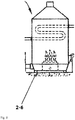
Fig. 3 shows a leachate and gas vacuum extracting treatment device of vehicle-driven type equipped with a vacuum pump (2-3), a gas and liquid separator (2-1), a high-temperature sterilizing treatment apparatus (2-2), a monitoring device (4), and a discharge device (2-8), wherein the leachate in the inside of landfill is pumped up through a vacuum pump (2-3) to be transferred to the gas and liquid separator (2-1) which is mounted on the vehicle. A sensor that can measure an amount of liquid and a pump are installed in the inside of the gas and liquid separator, such that the amount of liquid can be maintained constantly at the predetermined level. The gas and liquid separator is a separation system in a combined form of a cyclone that can separate gas from liquid using their centrifugal force and a vane plate separation technology where separation efficiency is increased by efficiently increasing the particle size of mists at the surface of flat planes. The leachate in the phase of liquid separated by the gas and liquid separator is transferred to the high-temperature sterilizing treatment apparatus, and the sterilized leachate by the high-temperature sterilizing treatment apparatus is subject to appropriate water treatment processes to be finally disposed. Also, bad odors and other substances in the phase of gas are subject to oxidation in a high-speed oxidation treatment apparatus (2-6) which is in situ installed, and then they are discharged in odorless and safe forms. -
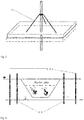
Fig. 4 illustrates a carcass combustion treatment device (3), which includes heat-generating rods (3-1) each of which can consume 10 kW-electric power at the maximum and a control panel (3-8) by which the temperatures of heat-generating rods (3-1) can be controlled in a range of 200∼850 °C. - Particularly, it should be noted as a key conception of the invention that the combustion device for complete combustion which had not been accomplished in the heat carbonization technology patent filed by the applicant is newly provided in the present invention.
- That is, air is injected through an air inlet provided on the top of the heat-generating rods, simultaneously with the operation of the heat-generating rods, and additionally, air is flowed into the underground, such that the ascended heat can permeate among soil media, i.e., soil gaps, and animal carcasses to combust them.
- In order to achieve the purpose of the combustion process, a vehicle-mounted vacuum pump (2-3) is operated simultaneously with the operation of the combustion process to extract the air that has been combusted in the underground to the ground above. There is an advantage that the tube wells which are already installed for the treatment of leachate may be used as the air extraction tube wells (2-4) for this extraction process, and they (2-4) may be readily removed or added, if necessary.
- The number of the heat-generating rods (3-1) to be installed may be adjusted, depending upon the area and volume of a landfill, and heat-generating coils (3-4) are mounted up to the height of 2 m from the lower end of the heat-generating rods (3-1) to be protected by carbon steel pipes (3-5). Further, in order to maximize the heat transfer power of the heat-generating rods (3-1), the carbon steel pipes (3-5) are punched with holes (3-6) each of which has a diameter of 4 cm in an interval of 5 cm so that the heat generated from the heat-generating coils (3-4) can be properly supplied to the dead livestock.
- Generally, the air heated by the heat-generating rod at a high temperature of 300°C to 500°C or so is transmitted through gaps of underground soil media, and thereby each heat-generating rod may have a combustion range of about 80cm to 160cm.
-
Fig. 5 illustrates a high-speed oxidation treatment apparatus (2-6), wherein the exhaust gas and vapors generated during the oxidation treatment are transferred to a simple high-speed oxidation treatment apparatus where bad odors, nitrogen oxides and sulfur compounds are finally disposed with oxidation, via a gas and liquid separator (2-1) which is installed in a vehicle-driven apparatus, a high-speed high-temperature sterilizing treatment apparatus (2-2), and a condenser (2-7). As a high-speed oxidation treatment apparatus (2-6), a commercially available product may be adopted. Also, it is operated at a temperature of 850°C and instantly performs the complete combustion of exhaust gas. -
Fig. 6 is a diagram showing an example of installation facility supports (5), which are coupled with the heat-generating rods (3-1) and the extraction tube wells (2-4), in order to secure stabilities of them and prevent purification facilities from being fallen or damaged due to soil subsidence that might happen during the operation of the process. -
Fig. 7 is a diagram illustrating an underground water level control system, which can constantly control the water level of the inside of a landfill not to be in contact with the heat-generating rods by installing measurement tube wells (2-5) and underground water extraction tube wells (2-4-1) in the outside of the landfill, in order to prevent a decrease in the efficiency of the oxidation process due to the inflow of underground water from the outside of the landfill during the process. - So far, the stabilizing treatment system of livestock landfill through in situ underground combustion in accordance with one embodiment of the present invention has been described, and hereinafter a stabilizing treatment method of livestock landfill through an in situ underground combustion using this system according to the present invention will be explained.
-
Fig. 8 illustrates a stabilizing treatment process of livestock landfill through in situ underground combustion according to the present invention. As illustrated inFig. 8 , the stabilizing treatment method of livestock landfill through in situ underground combustion according to this invention comprises a pre-treatment step; a temperature-rising step; a drying step; a combustion step; and a heat stabilizing step, and thereby it brings an improvement in which heat transfer among underground soil media can be efficiently achieved by injecting air or a slight amount of pure oxygen through an air inlet which is formed on the top of heat-generating rod, simultaneously with the operation of the heat-generating rods installed in livestock landfill, and additionally by flowing air into the livestock landfill. - Hereinafter, each step will be explained in detail. In the pre-treatment step, an underground water level is lowered in order to increase the efficiency of an underground combustion process, and the leachate generated from buried animal carcasses is treated. In the temperature-rising step, heat is continuously provided to the vicinity of the landfill where the animal carcasses are buried through heat-generating rods by injecting air along with the operation of the heat-generating rods, in order to form a condition (∼100°C) in which moisture possessed by the carcasses and soil pore water can be dried. In the drying step, the moisture possessed by the carcasses and the soil pore water is evaporated by maintaining the temperature at 100°C or so such that a combustion can occur efficiently. In the combustion step, the dried animal carcasses are combusted in a temperature range of 200∼850°C with an oxygen contained in the air to be flowed in the surroundings of carcasses or a pure oxygen in a slight amount to be injected in order to increase combustion efficiency, and then, the animal carcasses themselves become a heat source such that heat spreads out to their vicinity. Lastly, in the heat stabilizing step, the combustion is completed due to the absence of substances to be burned after the complete combustion of the animal carcasses at a temperature of 100∼250°C. If possible, it is preferable to collect and discharge combustion gases between these steps, and then, oxidize them. A slight amount of CO, NOx and SOx is produced between the combustion step and the heat stabilizing step.
-
Figs. 9(a), (b) are graphs showing heat treatment effects (temperature increase) in the underground in case that air intake was carried out approximately 20 hours after a heat source was sufficiently formed in the vicinity of heat-generating rods by injecting air in a state of maintaining the surface temperature of the heat-generating rods at 500∼700°C with a heater being turned on, wherein (a) shows heat treatment effects at a location away from a heat-generating rod by 40 cm and (b) shows heat treatment effects at a location away by 60 cm. They show that temperature was more rapidly increased when air injection (in the heat-generating rods) and air intake (in the underground landfill) were carried out together than when only air injection was carried out, such that it could maximize combustion effects by the dry combustion of animal carcasses buried in the underground. -
Figs. 10(a), (b) are graphs showing temperature measurement results after the operation of the system for 4 days in a state of maintaining the surface temperature of heat-generating rods at 500∼700°C, using the treatment method of the present invention, i.e., the technology that heat transfer within the underground soil media can be efficiently achieved by injecting air or a slight amount of pure oxygen into an air inlet formed on the top of heat-generating rods, simultaneously with the operation of the heat-generating rods installed in livestock landfill, and additionally by flowing air into the livestock landfill.Fig. 10 (a) is a result at a location away from the heat-generating rod by 50 cm, andFig. 10 (b) is a result at a location away by 80 cm. They show the fact that as a distance from the heat generating rods became closer, the temperature increased more quickly, depending upon the passage of time, such that the drying, combustion and heat stabilizing steps were smoothly carried out. In particular, it shows that at the location away from the heat-generating rod by 50 cm, temperature increased to 250°C or higher after 30 hours and combustion was carried out vigorously, and after then it was followed by the final heat stabilizing step as 70 hours passed. Accordingly, when considering economical aspects, it is suitable to have an individual combustion range of about 40 to 80 cm from a heat generating rod, that is, to arrange heat-generating rods adjacent to each other to be spaced in a distance of 80 to 160 cm for combustion treatment. - The present invention has been described above with reference to optimum embodiments. However, it is apparent that variations or equivalent embodiments by those skilled in the art can be effected within the scope of the present invention described in the above. Therefore, the true scope of right of the present invention should be determined by the technical ideas provided in the appended claims.
- The stabilizing treatment technology of livestock landfill through in situ underground combustion of the present invention makes it possible to prevent underground water pollution due to the outflow of leachate by fundamentally eliminating the discharge source of leachate, and to combust dead livestock in a stable way. Thus, it is cost-efficient when compared with the leachate treatment technologies and heat carbonization-based stabilizing treatment technology of livestock landfill which require a long-term monitoring and maintenance, and further it can prevent and improve risks of workers' being exposed to contagious viruses since it does not require an excavation process or a facility to incinerate the dead livestock that has been already buried.
Claims (12)
- A stabilizing treatment system of livestock landfill through in situ underground combustion for disposing swine carcasses, cow carcasses and poultry carcasses buried in a landfill, comprising:a heat-insulating rainwater barrier (1) for shielding rainwater;a leachate and gas vacuum extracting treatment device (2) for treating the leachate and gas from the heat-insulating rainwater barrier by vacuum extraction;a carcass combustion treatment device (3) for combusting the livestock carcasses buried in the landfill;a monitoring device (4) for monitoring underground livestock carcasses buried in the landfill; andan installation facility support (5) for supporting the above devices in a stable way,wherein the carcass combustion treatment device (3) has a plurality of heat-generating rods (3-1) depending on the areas to be treated, and a generator (3-2) connected to the heat-generating rods (3-1), such that the carcass combustion treatment device (3) dries the moisture, blood and oil components of the carcasses by providing heat through the heat-generating rods (3-1) and oxidizes the carcasses.
- A stabilizing treatment system of livestock landfill through in situ underground combustion of claim 1, wherein the heat-insulating rainwater barrier (1) comprises a ceramic fiber (1-1) made in a blanket form and a clay layer (1-2) for the protection of a heat insulating material.
- A stabilizing treatment system of livestock landfill through in situ underground combustion of claim 1, wherein the leachate and gas vacuum extracting treatment device (2) comprises a gas and liquid separator (2-1) for extracting the gas and liquid produced during oxidation under a reduced pressure, a high-temperature sterilizing treatment apparatus (2-2) for sterilizing the liquid vacuum-extracted at a high temperature, a vacuum pump (2-3), a plurality of extraction tube wells (2-4) for the treatment of the leachate and gas, a plurality of measurement tube wells (2-5) for underground water level control in the outside of landfill, a high-speed oxidation treatment apparatus (2-6), a condenser (2-7), and a discharge device (2-8).
- A stabilizing treatment system of livestock landfill through in situ underground combustion of claim 1, wherein the carcass combustion treatment device (3) further comprises a control panel (3-8) for controlling the temperature of heat-generating rods (3-1), and simultaneously with the operation of the heat-generating rods (3-1), air is injected through an air inlet provided on the top of the heat-generating rods (3-1) such that high-temperature air heated in the heat-generating rods (3-1) travels through gaps of underground soil media to oxidize animal carcasses.
- A stabilizing treatment system of livestock landfill through in situ underground combustion of claim 4, wherein an outer skin (3-3) is installed on the outside of the heat-generating rod (3-1).
- A stabilizing treatment system of livestock landfill through in situ underground combustion of claim 4, wherein the heat-generating rods (3-1) can be adjusted in a temperature range of 200°C to 850°C.
- A stabilizing treatment system of livestock landfill through in situ underground combustion of claim 4, wherein the heat-generating rods (3-1) are equipped with heat-generating coils (3-4) up to the height of 2 m from the lower end of the heat-generating rods (3-1), and the heat-generating coils (3-4) are protected by carbon steel pipes (3-5).
- A stabilizing treatment system of livestock landfill through in situ underground combustion of claim 7, wherein in order to maximize the heat transfer power of the heat-generating rods (3-1), the carbon steel pipes (3-5) are punched with holes (3-6) each having a diameter of 4 cm in an interval of 5 cm from each other so that the heat generated from the heat-generating coils (3-4) can be properly supplied to dead livestock.
- A stabilizing treatment system of livestock landfill through in situ underground combustion of claim 3, wherein each extraction tube well (2-4) of the gas and liquid vacuum extraction device (2) is equipped with a gauge such that it is controlled automatically or manually for the control of operation factors.
- A stabilizing treatment method of livestock landfill through in situ underground combustion for disposing swine carcasses, cow carcasses and poultry carcasses buried in a landfill by combustion using a stabilizing treatment system of livestock landfill according to any one of claims 1 to 9, which comprises,
a pre-treatment step for lowering an underground water level in order to increase the efficiency of an underground combustion process and treating leachate from buried animal carcasses;
a temperature-rising step for injecting air simultaneously with the operation of a plurality of heat-generating rods (3-1) installed in the underground landfill, and providing constant heat to the vicinity of the buried animal carcasses through the heat-generating rods (3-1) to form a condition (-100°C) in which moisture possessed by the carcasses and soil pore water can be dried;
a drying step for supplying heat continuously in a state of maintaining the temperature of 100°C or so to evaporate the moisture possessed by the carcasses and the soil pore water such that an efficient combustion can occur;
a combustion step for combusting the dried animal carcasses in a temperature range of 200∼850°C through an oxygen contained in the air to be flowed in the vicinity or a slight amount of pure oxygen injected in order to further increase combustion efficiency, wherein the animal carcasses themselves become a heat source such that heat spreads out to their vicinity; and,
a heat stabilizing step for completing the combustion at a temperature of 100-250 °C by the absence of substances to be burned after the complete combustion of the animal carcasses. - A stabilizing treatment method of livestock landfill through in situ underground combustion of claim 10, wherein between the said steps, the combustion gas is collected, discharged and then treated by oxidation.
- A stabilizing treatment method of livestock landfill through in situ underground combustion of claim 10, further comprising spacing the plurality of heat-generating rods (3-1) with respect to each other in a range of 80 ∼ 160 cm.
Applications Claiming Priority (2)
| Application Number | Priority Date | Filing Date | Title |
|---|---|---|---|
| KR20110031994A KR101097742B1 (en) | 2011-04-07 | 2011-04-07 | Stabilization Treatment System and Treatment Method for Livestock Landfill by In situ Underground Oxidation (Combustion) |
| PCT/KR2012/001774 WO2012138061A1 (en) | 2011-04-07 | 2012-03-12 | Processing system and method for stabilizing livestock reclaimed ground by on-site underground oxidation (combustion) |
Publications (3)
| Publication Number | Publication Date |
|---|---|
| EP2696141A1 EP2696141A1 (en) | 2014-02-12 |
| EP2696141A4 EP2696141A4 (en) | 2014-10-15 |
| EP2696141B1 true EP2696141B1 (en) | 2018-11-28 |
Family
ID=45506807
Family Applications (1)
| Application Number | Title | Priority Date | Filing Date |
|---|---|---|---|
| EP12768105.4A Not-in-force EP2696141B1 (en) | 2011-04-07 | 2012-03-12 | Processing system and method for stabilizing livestock reclaimed ground by on-site underground combustion |
Country Status (4)
| Country | Link |
|---|---|
| EP (1) | EP2696141B1 (en) |
| JP (1) | JP5771282B2 (en) |
| KR (1) | KR101097742B1 (en) |
| WO (1) | WO2012138061A1 (en) |
Families Citing this family (6)
| Publication number | Priority date | Publication date | Assignee | Title |
|---|---|---|---|---|
| KR102069787B1 (en) | 2018-04-09 | 2020-01-28 | 이성기 | Bacterial consortium for accelerating decomposition from stamped out animal |
| CN110762532B (en) * | 2019-11-08 | 2021-05-11 | 浙江天翔环保设备有限公司 | A refine oil and draw equipment for incinerating spoil |
| KR102348481B1 (en) * | 2020-02-13 | 2022-01-07 | 동아대학교 산학협력단 | Purification system for animal carcass disposal sites using oxygen supersaturated leachate cycle |
| CN111675559A (en) * | 2020-05-29 | 2020-09-18 | 广东益康生环保设备有限公司 | Complete equipment and method for treating solid waste in farm |
| CN114440227B (en) * | 2022-03-11 | 2024-08-09 | 江苏碳峰蓝节能科技有限公司 | Belt type in-situ oxidation device |
| CN118477873A (en) * | 2024-06-04 | 2024-08-13 | 香港理工大学深圳研究院 | In-situ treatment system and method for refuse landfill based on smoldering |
Family Cites Families (14)
| Publication number | Priority date | Publication date | Assignee | Title |
|---|---|---|---|---|
| JPH04118414A (en) * | 1990-09-10 | 1992-04-20 | Nippon Sogo Kenkyusho:Kk | Field solidification treatment of soil with waste refuse buried in |
| KR100332003B1 (en) * | 1999-07-22 | 2002-04-10 | 고학봉 | Apparatus for treating landfill leachate by using heat source of landfill gas |
| US6749368B2 (en) * | 2000-09-05 | 2004-06-15 | Daniel B. Stephens & Associates, Inc. | Design, monitoring and control of soil carburetors for degradation of volatile compounds |
| KR100478403B1 (en) * | 2000-11-13 | 2005-03-23 | 이엔브이이십일(주) | Landfill structure using concept of multi-layered reactors and method for operating the same |
| JP2002239493A (en) * | 2001-02-16 | 2002-08-27 | Goro Takagi | Treatment of water generated in the final disposal site |
| KR100397764B1 (en) | 2001-04-24 | 2003-09-19 | 아름다운 환경건설(주) | Restitutive apparatus for polluted soil driving by vehicles |
| JP4346268B2 (en) | 2001-12-12 | 2009-10-21 | 三井造船株式会社 | Waste treatment apparatus and waste treatment method |
| JP2003236496A (en) * | 2002-02-13 | 2003-08-26 | Oshima Shipbuilding Co Ltd | Pottery material consisting of livestock by-product processing system and processing residue |
| JP2005319456A (en) * | 2004-04-07 | 2005-11-17 | Nishida Kosan:Kk | Stabilization promotion method for waste landfill site |
| KR100440403B1 (en) * | 2004-05-04 | 2004-07-14 | 주식회사 지화이브 | Waste carbonizing disposer |
| KR100862377B1 (en) | 2007-08-20 | 2008-10-13 | 대한민국(관리부서:농촌진흥청) | Direct heated animal carcass processing device using vacuum state |
| KR101469535B1 (en) * | 2008-06-02 | 2014-12-08 | 농업법인우리생명 (주) | A deserted domestic animal land reclamation revival purification management method |
| KR20100082131A (en) * | 2009-01-08 | 2010-07-16 | 위승용 | System leachate-preventive , odor , virus remove for reclamation of avian influenza bird |
| KR101035500B1 (en) | 2009-08-12 | 2011-05-20 | (주)제이브이엠 | Remote check terminal of automatic medicine packing machine |
-
2011
- 2011-04-07 KR KR20110031994A patent/KR101097742B1/en active Active
-
2012
- 2012-03-12 EP EP12768105.4A patent/EP2696141B1/en not_active Not-in-force
- 2012-03-12 WO PCT/KR2012/001774 patent/WO2012138061A1/en not_active Ceased
- 2012-03-12 JP JP2013543117A patent/JP5771282B2/en not_active Expired - Fee Related
Non-Patent Citations (1)
| Title |
|---|
| None * |
Also Published As
| Publication number | Publication date |
|---|---|
| EP2696141A1 (en) | 2014-02-12 |
| WO2012138061A1 (en) | 2012-10-11 |
| KR101097742B1 (en) | 2011-12-23 |
| EP2696141A4 (en) | 2014-10-15 |
| JP5771282B2 (en) | 2015-08-26 |
| JP2014504206A (en) | 2014-02-20 |
Similar Documents
| Publication | Publication Date | Title |
|---|---|---|
| EP2696141A1 (en) | Processing system and method for stabilizing livestock reclaimed ground by on-site underground oxidation (combustion) | |
| CN103539333B (en) | System and method for drying sludge through waste heat of gas turbine | |
| CN206924608U (en) | Stench processing system for landfill leachate treatment station | |
| CN102069087B (en) | Fixed safety disposal device for animals with diseases by alkaline degradation | |
| KR101060741B1 (en) | Slaughter disposal method and slaughter disposal device to prevent the spread of infectious diseases, composting method of carcass organic material using the same | |
| KR101260653B1 (en) | Portable type incineration apparatus | |
| CN203360247U (en) | Comprehensive sludge treatment integrated equipment | |
| KR20170059735A (en) | Landfill Gas Treatment and Heat Energy Utilization System in aerobic Solid Waste Lnadfill | |
| JP2010058103A (en) | Apparatus for pyrolyzing organic substance by magnetic pneumatic means | |
| KR101160878B1 (en) | Mobile animal carcass processing method | |
| KR101160876B1 (en) | Mobile animal carcass processing device | |
| KR102059353B1 (en) | Carbonization incinerator of livestock body | |
| CN202028603U (en) | High temperature and high pressure medical solid waste on-site disposing device | |
| KR101131340B1 (en) | Management system for stabilizing livestock reclaimed land through heat carbonization of original site | |
| CN104858222A (en) | Soil restoration electromagnetic pyrolysis steam rotary furnace | |
| CN102125926B (en) | High temperature and high pressure on-site treating device for medical solid wastes | |
| CN203768250U (en) | Quick environment-friendly treating machine for waste livestock and poultry | |
| CN211218000U (en) | Heap thermal desorption treatment system for remediation of organic contaminated soil | |
| CN112387769A (en) | Micro negative pressure collecting and processing system for contaminated soil ex-situ remediation engineering | |
| KR20220063019A (en) | System for disposaling animals without bad smell | |
| CN105444159A (en) | In-situ deep-layer heating device and in-situ heating soil decontamination device with same | |
| KR101339848B1 (en) | movable-type treating apparatus of dead livestock | |
| KR101345398B1 (en) | System and method for ground heat treatment of original site | |
| KR101370569B1 (en) | Moving apparatus for highly pathogenic waste treatment | |
| JP2008126163A (en) | Garbage treatment machine equipped with crusher and disposer, electromagnetic induction heating and reverse osmosis membrane, photocatalyst, and organic waste drying and carbonization equipment |
Legal Events
| Date | Code | Title | Description |
|---|---|---|---|
| PUAI | Public reference made under article 153(3) epc to a published international application that has entered the european phase |
Free format text: ORIGINAL CODE: 0009012 |
|
| 17P | Request for examination filed |
Effective date: 20131025 |
|
| AK | Designated contracting states |
Kind code of ref document: A1 Designated state(s): AL AT BE BG CH CY CZ DE DK EE ES FI FR GB GR HR HU IE IS IT LI LT LU LV MC MK MT NL NO PL PT RO RS SE SI SK SM TR |
|
| DAX | Request for extension of the european patent (deleted) | ||
| A4 | Supplementary search report drawn up and despatched |
Effective date: 20140912 |
|
| RIC1 | Information provided on ipc code assigned before grant |
Ipc: C05F 1/00 20060101ALI20140908BHEP Ipc: F23G 5/10 20060101ALI20140908BHEP Ipc: B09B 5/00 20060101ALI20140908BHEP Ipc: F23G 5/04 20060101ALI20140908BHEP Ipc: F23G 1/00 20060101AFI20140908BHEP |
|
| GRAP | Despatch of communication of intention to grant a patent |
Free format text: ORIGINAL CODE: EPIDOSNIGR1 |
|
| STAA | Information on the status of an ep patent application or granted ep patent |
Free format text: STATUS: GRANT OF PATENT IS INTENDED |
|
| INTG | Intention to grant announced |
Effective date: 20180626 |
|
| GRAS | Grant fee paid |
Free format text: ORIGINAL CODE: EPIDOSNIGR3 |
|
| GRAA | (expected) grant |
Free format text: ORIGINAL CODE: 0009210 |
|
| STAA | Information on the status of an ep patent application or granted ep patent |
Free format text: STATUS: THE PATENT HAS BEEN GRANTED |
|
| AK | Designated contracting states |
Kind code of ref document: B1 Designated state(s): AL AT BE BG CH CY CZ DE DK EE ES FI FR GB GR HR HU IE IS IT LI LT LU LV MC MK MT NL NO PL PT RO RS SE SI SK SM TR |
|
| REG | Reference to a national code |
Ref country code: GB Ref legal event code: FG4D |
|
| REG | Reference to a national code |
Ref country code: CH Ref legal event code: EP |
|
| REG | Reference to a national code |
Ref country code: AT Ref legal event code: REF Ref document number: 1070662 Country of ref document: AT Kind code of ref document: T Effective date: 20181215 |
|
| REG | Reference to a national code |
Ref country code: DE Ref legal event code: R096 Ref document number: 602012054099 Country of ref document: DE |
|
| REG | Reference to a national code |
Ref country code: IE Ref legal event code: FG4D |
|
| REG | Reference to a national code |
Ref country code: NL Ref legal event code: MP Effective date: 20181128 |
|
| REG | Reference to a national code |
Ref country code: LT Ref legal event code: MG4D |
|
| REG | Reference to a national code |
Ref country code: AT Ref legal event code: MK05 Ref document number: 1070662 Country of ref document: AT Kind code of ref document: T Effective date: 20181128 |
|
| PG25 | Lapsed in a contracting state [announced via postgrant information from national office to epo] |
Ref country code: HR Free format text: LAPSE BECAUSE OF FAILURE TO SUBMIT A TRANSLATION OF THE DESCRIPTION OR TO PAY THE FEE WITHIN THE PRESCRIBED TIME-LIMIT Effective date: 20181128 Ref country code: NO Free format text: LAPSE BECAUSE OF FAILURE TO SUBMIT A TRANSLATION OF THE DESCRIPTION OR TO PAY THE FEE WITHIN THE PRESCRIBED TIME-LIMIT Effective date: 20190228 Ref country code: LT Free format text: LAPSE BECAUSE OF FAILURE TO SUBMIT A TRANSLATION OF THE DESCRIPTION OR TO PAY THE FEE WITHIN THE PRESCRIBED TIME-LIMIT Effective date: 20181128 Ref country code: ES Free format text: LAPSE BECAUSE OF FAILURE TO SUBMIT A TRANSLATION OF THE DESCRIPTION OR TO PAY THE FEE WITHIN THE PRESCRIBED TIME-LIMIT Effective date: 20181128 Ref country code: BG Free format text: LAPSE BECAUSE OF FAILURE TO SUBMIT A TRANSLATION OF THE DESCRIPTION OR TO PAY THE FEE WITHIN THE PRESCRIBED TIME-LIMIT Effective date: 20190228 Ref country code: LV Free format text: LAPSE BECAUSE OF FAILURE TO SUBMIT A TRANSLATION OF THE DESCRIPTION OR TO PAY THE FEE WITHIN THE PRESCRIBED TIME-LIMIT Effective date: 20181128 Ref country code: FI Free format text: LAPSE BECAUSE OF FAILURE TO SUBMIT A TRANSLATION OF THE DESCRIPTION OR TO PAY THE FEE WITHIN THE PRESCRIBED TIME-LIMIT Effective date: 20181128 Ref country code: IS Free format text: LAPSE BECAUSE OF FAILURE TO SUBMIT A TRANSLATION OF THE DESCRIPTION OR TO PAY THE FEE WITHIN THE PRESCRIBED TIME-LIMIT Effective date: 20190328 Ref country code: AT Free format text: LAPSE BECAUSE OF FAILURE TO SUBMIT A TRANSLATION OF THE DESCRIPTION OR TO PAY THE FEE WITHIN THE PRESCRIBED TIME-LIMIT Effective date: 20181128 |
|
| PG25 | Lapsed in a contracting state [announced via postgrant information from national office to epo] |
Ref country code: RS Free format text: LAPSE BECAUSE OF FAILURE TO SUBMIT A TRANSLATION OF THE DESCRIPTION OR TO PAY THE FEE WITHIN THE PRESCRIBED TIME-LIMIT Effective date: 20181128 Ref country code: GR Free format text: LAPSE BECAUSE OF FAILURE TO SUBMIT A TRANSLATION OF THE DESCRIPTION OR TO PAY THE FEE WITHIN THE PRESCRIBED TIME-LIMIT Effective date: 20190301 Ref country code: AL Free format text: LAPSE BECAUSE OF FAILURE TO SUBMIT A TRANSLATION OF THE DESCRIPTION OR TO PAY THE FEE WITHIN THE PRESCRIBED TIME-LIMIT Effective date: 20181128 Ref country code: SE Free format text: LAPSE BECAUSE OF FAILURE TO SUBMIT A TRANSLATION OF THE DESCRIPTION OR TO PAY THE FEE WITHIN THE PRESCRIBED TIME-LIMIT Effective date: 20181128 Ref country code: PT Free format text: LAPSE BECAUSE OF FAILURE TO SUBMIT A TRANSLATION OF THE DESCRIPTION OR TO PAY THE FEE WITHIN THE PRESCRIBED TIME-LIMIT Effective date: 20190328 |
|
| PG25 | Lapsed in a contracting state [announced via postgrant information from national office to epo] |
Ref country code: NL Free format text: LAPSE BECAUSE OF FAILURE TO SUBMIT A TRANSLATION OF THE DESCRIPTION OR TO PAY THE FEE WITHIN THE PRESCRIBED TIME-LIMIT Effective date: 20181128 |
|
| PG25 | Lapsed in a contracting state [announced via postgrant information from national office to epo] |
Ref country code: PL Free format text: LAPSE BECAUSE OF FAILURE TO SUBMIT A TRANSLATION OF THE DESCRIPTION OR TO PAY THE FEE WITHIN THE PRESCRIBED TIME-LIMIT Effective date: 20181128 Ref country code: DK Free format text: LAPSE BECAUSE OF FAILURE TO SUBMIT A TRANSLATION OF THE DESCRIPTION OR TO PAY THE FEE WITHIN THE PRESCRIBED TIME-LIMIT Effective date: 20181128 Ref country code: IT Free format text: LAPSE BECAUSE OF FAILURE TO SUBMIT A TRANSLATION OF THE DESCRIPTION OR TO PAY THE FEE WITHIN THE PRESCRIBED TIME-LIMIT Effective date: 20181128 Ref country code: CZ Free format text: LAPSE BECAUSE OF FAILURE TO SUBMIT A TRANSLATION OF THE DESCRIPTION OR TO PAY THE FEE WITHIN THE PRESCRIBED TIME-LIMIT Effective date: 20181128 |
|
| REG | Reference to a national code |
Ref country code: DE Ref legal event code: R097 Ref document number: 602012054099 Country of ref document: DE |
|
| PG25 | Lapsed in a contracting state [announced via postgrant information from national office to epo] |
Ref country code: SK Free format text: LAPSE BECAUSE OF FAILURE TO SUBMIT A TRANSLATION OF THE DESCRIPTION OR TO PAY THE FEE WITHIN THE PRESCRIBED TIME-LIMIT Effective date: 20181128 Ref country code: SM Free format text: LAPSE BECAUSE OF FAILURE TO SUBMIT A TRANSLATION OF THE DESCRIPTION OR TO PAY THE FEE WITHIN THE PRESCRIBED TIME-LIMIT Effective date: 20181128 Ref country code: EE Free format text: LAPSE BECAUSE OF FAILURE TO SUBMIT A TRANSLATION OF THE DESCRIPTION OR TO PAY THE FEE WITHIN THE PRESCRIBED TIME-LIMIT Effective date: 20181128 Ref country code: RO Free format text: LAPSE BECAUSE OF FAILURE TO SUBMIT A TRANSLATION OF THE DESCRIPTION OR TO PAY THE FEE WITHIN THE PRESCRIBED TIME-LIMIT Effective date: 20181128 |
|
| REG | Reference to a national code |
Ref country code: DE Ref legal event code: R119 Ref document number: 602012054099 Country of ref document: DE |
|
| PLBE | No opposition filed within time limit |
Free format text: ORIGINAL CODE: 0009261 |
|
| STAA | Information on the status of an ep patent application or granted ep patent |
Free format text: STATUS: NO OPPOSITION FILED WITHIN TIME LIMIT |
|
| PG25 | Lapsed in a contracting state [announced via postgrant information from national office to epo] |
Ref country code: MC Free format text: LAPSE BECAUSE OF FAILURE TO SUBMIT A TRANSLATION OF THE DESCRIPTION OR TO PAY THE FEE WITHIN THE PRESCRIBED TIME-LIMIT Effective date: 20181128 Ref country code: SI Free format text: LAPSE BECAUSE OF FAILURE TO SUBMIT A TRANSLATION OF THE DESCRIPTION OR TO PAY THE FEE WITHIN THE PRESCRIBED TIME-LIMIT Effective date: 20181128 |
|
| REG | Reference to a national code |
Ref country code: CH Ref legal event code: PL |
|
| 26N | No opposition filed |
Effective date: 20190829 |
|
| PG25 | Lapsed in a contracting state [announced via postgrant information from national office to epo] |
Ref country code: LU Free format text: LAPSE BECAUSE OF NON-PAYMENT OF DUE FEES Effective date: 20190312 |
|
| REG | Reference to a national code |
Ref country code: BE Ref legal event code: MM Effective date: 20190331 |
|
| PG25 | Lapsed in a contracting state [announced via postgrant information from national office to epo] |
Ref country code: IE Free format text: LAPSE BECAUSE OF NON-PAYMENT OF DUE FEES Effective date: 20190312 Ref country code: CH Free format text: LAPSE BECAUSE OF NON-PAYMENT OF DUE FEES Effective date: 20190331 Ref country code: DE Free format text: LAPSE BECAUSE OF NON-PAYMENT OF DUE FEES Effective date: 20191001 Ref country code: LI Free format text: LAPSE BECAUSE OF NON-PAYMENT OF DUE FEES Effective date: 20190331 |
|
| PG25 | Lapsed in a contracting state [announced via postgrant information from national office to epo] |
Ref country code: FR Free format text: LAPSE BECAUSE OF NON-PAYMENT OF DUE FEES Effective date: 20190331 Ref country code: BE Free format text: LAPSE BECAUSE OF NON-PAYMENT OF DUE FEES Effective date: 20190331 |
|
| PG25 | Lapsed in a contracting state [announced via postgrant information from national office to epo] |
Ref country code: TR Free format text: LAPSE BECAUSE OF FAILURE TO SUBMIT A TRANSLATION OF THE DESCRIPTION OR TO PAY THE FEE WITHIN THE PRESCRIBED TIME-LIMIT Effective date: 20181128 |
|
| PG25 | Lapsed in a contracting state [announced via postgrant information from national office to epo] |
Ref country code: MT Free format text: LAPSE BECAUSE OF NON-PAYMENT OF DUE FEES Effective date: 20190312 |
|
| PG25 | Lapsed in a contracting state [announced via postgrant information from national office to epo] |
Ref country code: CY Free format text: LAPSE BECAUSE OF FAILURE TO SUBMIT A TRANSLATION OF THE DESCRIPTION OR TO PAY THE FEE WITHIN THE PRESCRIBED TIME-LIMIT Effective date: 20181128 |
|
| PG25 | Lapsed in a contracting state [announced via postgrant information from national office to epo] |
Ref country code: HU Free format text: LAPSE BECAUSE OF FAILURE TO SUBMIT A TRANSLATION OF THE DESCRIPTION OR TO PAY THE FEE WITHIN THE PRESCRIBED TIME-LIMIT; INVALID AB INITIO Effective date: 20120312 |
|
| PGFP | Annual fee paid to national office [announced via postgrant information from national office to epo] |
Ref country code: GB Payment date: 20220318 Year of fee payment: 11 |
|
| PG25 | Lapsed in a contracting state [announced via postgrant information from national office to epo] |
Ref country code: MK Free format text: LAPSE BECAUSE OF FAILURE TO SUBMIT A TRANSLATION OF THE DESCRIPTION OR TO PAY THE FEE WITHIN THE PRESCRIBED TIME-LIMIT Effective date: 20181128 |
|
| GBPC | Gb: european patent ceased through non-payment of renewal fee |
Effective date: 20230312 |
|
| PG25 | Lapsed in a contracting state [announced via postgrant information from national office to epo] |
Ref country code: GB Free format text: LAPSE BECAUSE OF NON-PAYMENT OF DUE FEES Effective date: 20230312 |
|
| PG25 | Lapsed in a contracting state [announced via postgrant information from national office to epo] |
Ref country code: GB Free format text: LAPSE BECAUSE OF NON-PAYMENT OF DUE FEES Effective date: 20230312 |