JP5771282B2 - System and method for stabilizing livestock landfill by in situ oxidation (combustion) - Google Patents
System and method for stabilizing livestock landfill by in situ oxidation (combustion) Download PDFInfo
- Publication number
- JP5771282B2 JP5771282B2 JP2013543117A JP2013543117A JP5771282B2 JP 5771282 B2 JP5771282 B2 JP 5771282B2 JP 2013543117 A JP2013543117 A JP 2013543117A JP 2013543117 A JP2013543117 A JP 2013543117A JP 5771282 B2 JP5771282 B2 JP 5771282B2
- Authority
- JP
- Japan
- Prior art keywords
- landfill
- oxidation
- heating rod
- heat
- livestock
- Prior art date
- Legal status (The legal status is an assumption and is not a legal conclusion. Google has not performed a legal analysis and makes no representation as to the accuracy of the status listed.)
- Expired - Fee Related
Links
- 230000003647 oxidation Effects 0.000 title claims description 57
- 238000007254 oxidation reaction Methods 0.000 title claims description 57
- 238000002485 combustion reaction Methods 0.000 title claims description 52
- 244000144972 livestock Species 0.000 title claims description 51
- 238000000034 method Methods 0.000 title claims description 32
- 238000011065 in-situ storage Methods 0.000 title claims description 26
- 230000000087 stabilizing effect Effects 0.000 title claims description 4
- 238000010438 heat treatment Methods 0.000 claims description 60
- 230000006641 stabilisation Effects 0.000 claims description 38
- 238000011105 stabilization Methods 0.000 claims description 38
- 239000007789 gas Substances 0.000 claims description 32
- 238000000605 extraction Methods 0.000 claims description 26
- 239000010868 animal carcass Substances 0.000 claims description 24
- XLYOFNOQVPJJNP-UHFFFAOYSA-N water Substances O XLYOFNOQVPJJNP-UHFFFAOYSA-N 0.000 claims description 24
- 238000012545 processing Methods 0.000 claims description 21
- 230000008569 process Effects 0.000 claims description 19
- 239000007788 liquid Substances 0.000 claims description 17
- 239000002689 soil Substances 0.000 claims description 17
- 239000003673 groundwater Substances 0.000 claims description 13
- 238000009434 installation Methods 0.000 claims description 8
- 238000001035 drying Methods 0.000 claims description 7
- 230000001590 oxidative effect Effects 0.000 claims description 7
- 230000001954 sterilising effect Effects 0.000 claims description 7
- 241001465754 Metazoa Species 0.000 claims description 6
- 239000000919 ceramic Substances 0.000 claims description 6
- 239000000835 fiber Substances 0.000 claims description 6
- 238000012806 monitoring device Methods 0.000 claims description 6
- 239000011148 porous material Substances 0.000 claims description 6
- 238000004659 sterilization and disinfection Methods 0.000 claims description 6
- 229910000975 Carbon steel Inorganic materials 0.000 claims description 5
- 239000010962 carbon steel Substances 0.000 claims description 5
- 239000004927 clay Substances 0.000 claims description 5
- 239000011810 insulating material Substances 0.000 claims description 5
- 238000012546 transfer Methods 0.000 claims description 5
- MYMOFIZGZYHOMD-UHFFFAOYSA-N Dioxygen Chemical compound O=O MYMOFIZGZYHOMD-UHFFFAOYSA-N 0.000 claims description 4
- 230000020169 heat generation Effects 0.000 claims description 4
- 238000002347 injection Methods 0.000 claims description 4
- 239000007924 injection Substances 0.000 claims description 4
- QVGXLLKOCUKJST-UHFFFAOYSA-N atomic oxygen Chemical compound [O] QVGXLLKOCUKJST-UHFFFAOYSA-N 0.000 claims description 3
- 239000008280 blood Substances 0.000 claims description 3
- 210000004369 blood Anatomy 0.000 claims description 3
- 238000012544 monitoring process Methods 0.000 claims description 3
- 229910052760 oxygen Inorganic materials 0.000 claims description 3
- 239000001301 oxygen Substances 0.000 claims description 3
- 239000000567 combustion gas Substances 0.000 claims description 2
- 239000000463 material Substances 0.000 claims description 2
- 239000003921 oil Substances 0.000 claims description 2
- 230000000903 blocking effect Effects 0.000 claims 1
- 238000007781 pre-processing Methods 0.000 claims 1
- 238000005086 pumping Methods 0.000 claims 1
- 239000011800 void material Substances 0.000 claims 1
- 238000005516 engineering process Methods 0.000 description 14
- 238000010586 diagram Methods 0.000 description 7
- 241000283690 Bos taurus Species 0.000 description 6
- 230000000694 effects Effects 0.000 description 6
- 238000009412 basement excavation Methods 0.000 description 5
- 201000010099 disease Diseases 0.000 description 5
- 208000037265 diseases, disorders, signs and symptoms Diseases 0.000 description 5
- 241000700605 Viruses Species 0.000 description 4
- 230000004888 barrier function Effects 0.000 description 4
- 238000009933 burial Methods 0.000 description 4
- 238000003763 carbonization Methods 0.000 description 4
- 238000000926 separation method Methods 0.000 description 4
- 244000052616 bacterial pathogen Species 0.000 description 3
- 238000011109 contamination Methods 0.000 description 3
- 230000007774 longterm Effects 0.000 description 3
- 238000003672 processing method Methods 0.000 description 3
- 230000003612 virological effect Effects 0.000 description 3
- 239000002699 waste material Substances 0.000 description 3
- 208000007212 Foot-and-Mouth Disease Diseases 0.000 description 2
- 241000710198 Foot-and-mouth disease virus Species 0.000 description 2
- 241000282887 Suidae Species 0.000 description 2
- 206010064097 avian influenza Diseases 0.000 description 2
- 230000005540 biological transmission Effects 0.000 description 2
- 238000010276 construction Methods 0.000 description 2
- 208000015181 infectious disease Diseases 0.000 description 2
- 230000002458 infectious effect Effects 0.000 description 2
- 238000012423 maintenance Methods 0.000 description 2
- 238000001556 precipitation Methods 0.000 description 2
- 238000011112 process operation Methods 0.000 description 2
- 238000000746 purification Methods 0.000 description 2
- 239000004576 sand Substances 0.000 description 2
- 239000000126 substance Substances 0.000 description 2
- 206010008631 Cholera Diseases 0.000 description 1
- 206010013647 Drowning Diseases 0.000 description 1
- 208000002979 Influenza in Birds Diseases 0.000 description 1
- 241001493546 Suina Species 0.000 description 1
- 241000282898 Sus scrofa Species 0.000 description 1
- 239000000809 air pollutant Substances 0.000 description 1
- 231100001243 air pollutant Toxicity 0.000 description 1
- 230000008901 benefit Effects 0.000 description 1
- 238000009529 body temperature measurement Methods 0.000 description 1
- 230000015556 catabolic process Effects 0.000 description 1
- 238000009841 combustion method Methods 0.000 description 1
- 239000002361 compost Substances 0.000 description 1
- 238000009264 composting Methods 0.000 description 1
- 238000009833 condensation Methods 0.000 description 1
- 230000005494 condensation Effects 0.000 description 1
- 238000000354 decomposition reaction Methods 0.000 description 1
- 238000006731 degradation reaction Methods 0.000 description 1
- 230000008034 disappearance Effects 0.000 description 1
- 230000007613 environmental effect Effects 0.000 description 1
- 238000001704 evaporation Methods 0.000 description 1
- 239000000284 extract Substances 0.000 description 1
- 230000036541 health Effects 0.000 description 1
- 230000001939 inductive effect Effects 0.000 description 1
- 230000008595 infiltration Effects 0.000 description 1
- 238000001764 infiltration Methods 0.000 description 1
- 238000009413 insulation Methods 0.000 description 1
- 238000010169 landfilling Methods 0.000 description 1
- 239000012528 membrane Substances 0.000 description 1
- 244000000010 microbial pathogen Species 0.000 description 1
- 244000005700 microbiome Species 0.000 description 1
- 239000003595 mist Substances 0.000 description 1
- 238000012986 modification Methods 0.000 description 1
- 230000004048 modification Effects 0.000 description 1
- 150000004767 nitrides Chemical class 0.000 description 1
- 235000019645 odor Nutrition 0.000 description 1
- 230000009965 odorless effect Effects 0.000 description 1
- 239000007800 oxidant agent Substances 0.000 description 1
- 239000002245 particle Substances 0.000 description 1
- 244000052769 pathogen Species 0.000 description 1
- 244000144977 poultry Species 0.000 description 1
- 230000005180 public health Effects 0.000 description 1
- 150000003464 sulfur compounds Chemical class 0.000 description 1
Images


Classifications
-
- F—MECHANICAL ENGINEERING; LIGHTING; HEATING; WEAPONS; BLASTING
- F23—COMBUSTION APPARATUS; COMBUSTION PROCESSES
- F23G—CREMATION FURNACES; CONSUMING WASTE PRODUCTS BY COMBUSTION
- F23G1/00—Furnaces for cremation of human or animal carcasses
-
- B—PERFORMING OPERATIONS; TRANSPORTING
- B09—DISPOSAL OF SOLID WASTE; RECLAMATION OF CONTAMINATED SOIL
- B09B—DISPOSAL OF SOLID WASTE
- B09B1/00—Dumping solid waste
-
- B—PERFORMING OPERATIONS; TRANSPORTING
- B09—DISPOSAL OF SOLID WASTE; RECLAMATION OF CONTAMINATED SOIL
- B09B—DISPOSAL OF SOLID WASTE
- B09B3/00—Destroying solid waste or transforming solid waste into something useful or harmless
- B09B3/40—Destroying solid waste or transforming solid waste into something useful or harmless involving thermal treatment, e.g. evaporation
-
- B—PERFORMING OPERATIONS; TRANSPORTING
- B09—DISPOSAL OF SOLID WASTE; RECLAMATION OF CONTAMINATED SOIL
- B09B—DISPOSAL OF SOLID WASTE
- B09B5/00—Operations not covered by a single other subclass or by a single other group in this subclass
-
- C—CHEMISTRY; METALLURGY
- C05—FERTILISERS; MANUFACTURE THEREOF
- C05F—ORGANIC FERTILISERS NOT COVERED BY SUBCLASSES C05B, C05C, e.g. FERTILISERS FROM WASTE OR REFUSE
- C05F1/00—Fertilisers made from animal corpses, or parts thereof
-
- C—CHEMISTRY; METALLURGY
- C05—FERTILISERS; MANUFACTURE THEREOF
- C05F—ORGANIC FERTILISERS NOT COVERED BY SUBCLASSES C05B, C05C, e.g. FERTILISERS FROM WASTE OR REFUSE
- C05F11/00—Other organic fertilisers
-
- F—MECHANICAL ENGINEERING; LIGHTING; HEATING; WEAPONS; BLASTING
- F23—COMBUSTION APPARATUS; COMBUSTION PROCESSES
- F23G—CREMATION FURNACES; CONSUMING WASTE PRODUCTS BY COMBUSTION
- F23G5/00—Incineration of waste; Incinerator constructions; Details, accessories or control therefor
- F23G5/02—Incineration of waste; Incinerator constructions; Details, accessories or control therefor with pretreatment
- F23G5/04—Incineration of waste; Incinerator constructions; Details, accessories or control therefor with pretreatment drying
-
- F—MECHANICAL ENGINEERING; LIGHTING; HEATING; WEAPONS; BLASTING
- F23—COMBUSTION APPARATUS; COMBUSTION PROCESSES
- F23G—CREMATION FURNACES; CONSUMING WASTE PRODUCTS BY COMBUSTION
- F23G5/00—Incineration of waste; Incinerator constructions; Details, accessories or control therefor
- F23G5/08—Incineration of waste; Incinerator constructions; Details, accessories or control therefor having supplementary heating
- F23G5/10—Incineration of waste; Incinerator constructions; Details, accessories or control therefor having supplementary heating electric
-
- F—MECHANICAL ENGINEERING; LIGHTING; HEATING; WEAPONS; BLASTING
- F23—COMBUSTION APPARATUS; COMBUSTION PROCESSES
- F23G—CREMATION FURNACES; CONSUMING WASTE PRODUCTS BY COMBUSTION
- F23G5/00—Incineration of waste; Incinerator constructions; Details, accessories or control therefor
- F23G5/08—Incineration of waste; Incinerator constructions; Details, accessories or control therefor having supplementary heating
- F23G5/14—Incineration of waste; Incinerator constructions; Details, accessories or control therefor having supplementary heating including secondary combustion
- F23G5/16—Incineration of waste; Incinerator constructions; Details, accessories or control therefor having supplementary heating including secondary combustion in a separate combustion chamber
- F23G5/165—Incineration of waste; Incinerator constructions; Details, accessories or control therefor having supplementary heating including secondary combustion in a separate combustion chamber arranged at a different level
-
- F—MECHANICAL ENGINEERING; LIGHTING; HEATING; WEAPONS; BLASTING
- F23—COMBUSTION APPARATUS; COMBUSTION PROCESSES
- F23G—CREMATION FURNACES; CONSUMING WASTE PRODUCTS BY COMBUSTION
- F23G5/00—Incineration of waste; Incinerator constructions; Details, accessories or control therefor
- F23G5/34—Incineration of waste; Incinerator constructions; Details, accessories or control therefor the waste being burnt in a pit or arranged in a heap for combustion
-
- F—MECHANICAL ENGINEERING; LIGHTING; HEATING; WEAPONS; BLASTING
- F23—COMBUSTION APPARATUS; COMBUSTION PROCESSES
- F23G—CREMATION FURNACES; CONSUMING WASTE PRODUCTS BY COMBUSTION
- F23G5/00—Incineration of waste; Incinerator constructions; Details, accessories or control therefor
- F23G5/50—Control or safety arrangements
-
- F—MECHANICAL ENGINEERING; LIGHTING; HEATING; WEAPONS; BLASTING
- F23—COMBUSTION APPARATUS; COMBUSTION PROCESSES
- F23G—CREMATION FURNACES; CONSUMING WASTE PRODUCTS BY COMBUSTION
- F23G7/00—Incinerators or other apparatus for consuming industrial waste, e.g. chemicals
- F23G7/06—Incinerators or other apparatus for consuming industrial waste, e.g. chemicals of waste gases or noxious gases, e.g. exhaust gases
- F23G7/061—Incinerators or other apparatus for consuming industrial waste, e.g. chemicals of waste gases or noxious gases, e.g. exhaust gases with supplementary heating
- F23G7/063—Incinerators or other apparatus for consuming industrial waste, e.g. chemicals of waste gases or noxious gases, e.g. exhaust gases with supplementary heating electric heating
-
- F—MECHANICAL ENGINEERING; LIGHTING; HEATING; WEAPONS; BLASTING
- F23—COMBUSTION APPARATUS; COMBUSTION PROCESSES
- F23G—CREMATION FURNACES; CONSUMING WASTE PRODUCTS BY COMBUSTION
- F23G7/00—Incinerators or other apparatus for consuming industrial waste, e.g. chemicals
- F23G7/14—Incinerators or other apparatus for consuming industrial waste, e.g. chemicals of contaminated soil, e.g. by oil
-
- B—PERFORMING OPERATIONS; TRANSPORTING
- B09—DISPOSAL OF SOLID WASTE; RECLAMATION OF CONTAMINATED SOIL
- B09B—DISPOSAL OF SOLID WASTE
- B09B1/00—Dumping solid waste
- B09B1/004—Covering of dumping sites
-
- F—MECHANICAL ENGINEERING; LIGHTING; HEATING; WEAPONS; BLASTING
- F23—COMBUSTION APPARATUS; COMBUSTION PROCESSES
- F23G—CREMATION FURNACES; CONSUMING WASTE PRODUCTS BY COMBUSTION
- F23G2207/00—Control
- F23G2207/40—Supplementary heat supply
-
- Y—GENERAL TAGGING OF NEW TECHNOLOGICAL DEVELOPMENTS; GENERAL TAGGING OF CROSS-SECTIONAL TECHNOLOGIES SPANNING OVER SEVERAL SECTIONS OF THE IPC; TECHNICAL SUBJECTS COVERED BY FORMER USPC CROSS-REFERENCE ART COLLECTIONS [XRACs] AND DIGESTS
- Y02—TECHNOLOGIES OR APPLICATIONS FOR MITIGATION OR ADAPTATION AGAINST CLIMATE CHANGE
- Y02A—TECHNOLOGIES FOR ADAPTATION TO CLIMATE CHANGE
- Y02A40/00—Adaptation technologies in agriculture, forestry, livestock or agroalimentary production
- Y02A40/10—Adaptation technologies in agriculture, forestry, livestock or agroalimentary production in agriculture
- Y02A40/20—Fertilizers of biological origin, e.g. guano or fertilizers made from animal corpses
-
- Y—GENERAL TAGGING OF NEW TECHNOLOGICAL DEVELOPMENTS; GENERAL TAGGING OF CROSS-SECTIONAL TECHNOLOGIES SPANNING OVER SEVERAL SECTIONS OF THE IPC; TECHNICAL SUBJECTS COVERED BY FORMER USPC CROSS-REFERENCE ART COLLECTIONS [XRACs] AND DIGESTS
- Y02—TECHNOLOGIES OR APPLICATIONS FOR MITIGATION OR ADAPTATION AGAINST CLIMATE CHANGE
- Y02E—REDUCTION OF GREENHOUSE GAS [GHG] EMISSIONS, RELATED TO ENERGY GENERATION, TRANSMISSION OR DISTRIBUTION
- Y02E20/00—Combustion technologies with mitigation potential
- Y02E20/12—Heat utilisation in combustion or incineration of waste
-
- Y—GENERAL TAGGING OF NEW TECHNOLOGICAL DEVELOPMENTS; GENERAL TAGGING OF CROSS-SECTIONAL TECHNOLOGIES SPANNING OVER SEVERAL SECTIONS OF THE IPC; TECHNICAL SUBJECTS COVERED BY FORMER USPC CROSS-REFERENCE ART COLLECTIONS [XRACs] AND DIGESTS
- Y02—TECHNOLOGIES OR APPLICATIONS FOR MITIGATION OR ADAPTATION AGAINST CLIMATE CHANGE
- Y02P—CLIMATE CHANGE MITIGATION TECHNOLOGIES IN THE PRODUCTION OR PROCESSING OF GOODS
- Y02P20/00—Technologies relating to chemical industry
- Y02P20/141—Feedstock
- Y02P20/145—Feedstock the feedstock being materials of biological origin
-
- Y—GENERAL TAGGING OF NEW TECHNOLOGICAL DEVELOPMENTS; GENERAL TAGGING OF CROSS-SECTIONAL TECHNOLOGIES SPANNING OVER SEVERAL SECTIONS OF THE IPC; TECHNICAL SUBJECTS COVERED BY FORMER USPC CROSS-REFERENCE ART COLLECTIONS [XRACs] AND DIGESTS
- Y02—TECHNOLOGIES OR APPLICATIONS FOR MITIGATION OR ADAPTATION AGAINST CLIMATE CHANGE
- Y02W—CLIMATE CHANGE MITIGATION TECHNOLOGIES RELATED TO WASTEWATER TREATMENT OR WASTE MANAGEMENT
- Y02W30/00—Technologies for solid waste management
- Y02W30/30—Landfill technologies aiming to mitigate methane emissions
Description
本発明は埋め立て処理された斃死豚、斃死牛および斃死家禽類の酸化処理システムに関するものであって、より詳しくは家畜斃死体が埋没した埋立地に浸出水を抽出して適切に殺菌処理した後、発熱棒を設置して稼動させることによって、埋没処理された家畜死体廃棄物を短期間に加熱して酸化(燃焼)させながら排出ガスを酸化させて、衛生的で親環境的に処理する、原位置地中酸化(燃焼)による家畜埋立地の安定化処理技術に関するものである。 The present invention relates to an oxidation treatment system for dying pigs, dying cattle and moribund poultry that have been landfilled, and more specifically, after extracting leachate into a landfill where livestock corpses were buried and appropriately sterilizing them By installing and operating a heating rod, the livestock carcass waste that has been buried is heated and oxidized (burned) in a short period of time to oxidize the exhaust gas and treat it hygienically and environmentally. The present invention relates to stabilization technology for livestock landfills by in-situ oxidation (combustion).
最近、各国の畜産業は鳥インフルエンザ(avian influenza)、狂牛病、豚コレラ、口蹄疫のようなウイルス性疾病の頻繁な発生と全国的な拡散によって莫大な被害を被っている。また、ウイルス性畜産疾病と判定されると、病原菌の拡散防止のために発生農場500m以内のすべての偶蹄類(artiodactyla)家畜を殺処分埋没または焼却して処理するように規制していて、殺処分方法により浸出水流出、大気汚染物質放出のような環境問題のために国民健康が絶えず脅威を受けているのが実情である。 Recently, the livestock industry in each country has suffered enormous damage due to the frequent occurrence and nationwide spread of viral diseases such as avian influenza, mad cow disease, swine cholera and foot-and-mouth disease. In addition, if it is determined as a viral livestock disease, all artiodactyla livestock within 500m of the farm where it is generated is controlled to be slaughtered, buried or incinerated in order to prevent the spread of pathogenic bacteria. The reality is that national health is constantly threatened by environmental problems such as leachate spills and air pollutant releases depending on disposal methods.
大韓民国農林水産食品部の資料によれば、口蹄疫、狂牛病、そして鳥インフルエンザで斃死した家畜類の個体数は2010年と2011年現在牛15万頭、豚314万頭、AI545万羽が殺処分され、ほとんどすべての斃死家畜廃棄物は埋没して処理され、埋没地数は全国96個市郡区の4,632個所に至っている。 According to the Korea Ministry of Agriculture, Forestry and Fisheries Food Department, the number of livestock drowned by foot-and-mouth disease, mad cow disease, and bird flu is 150,000 cattle, 3.14 million pigs and 5.45 million AIs killed as of 2010 and 2011 Almost all drowned livestock waste has been disposed of and disposed of, and the number of buried sites has reached 4,632 locations in 96 cities and districts nationwide.
ウイルス性畜産疾病にかかった家畜類の埋立/埋没を通じた殺処分が病原菌の拡散を防止し相対的に費用経済的な処理方法ではあるが、微生物による自然分解のためには相当な時間が要求され分解過程が進行される間に絶えず浸出水が流出するために2次汚染を誘発する短所がある。また、斃死体埋立地の土壌沈下問題によって敷地の活用性が制約を受ける短所がある。 Although disposal of livestock affected by viral livestock disease through landfill / burial is a relatively cost-effective treatment method that prevents the spread of pathogenic bacteria, it requires considerable time for natural degradation by microorganisms. However, since the leachate constantly flows out during the decomposition process, there is a disadvantage inducing secondary contamination. In addition, there is a disadvantage that the utility of the site is limited by the soil settlement problem of the corpse landfill.
埋立その他にも、焼却、高温スチーム、および堆肥化方法があるが、伝染性の高いウイルスによって斃死した家畜を堆肥化することは病原菌伝染の危険性のため現実的に不可能である。また、焼却および高温スチーム処理方法は埋立以前に工法が実行される場合のみに費用経済性を確保することができる。つまり、既埋め立てられた廃棄物を掘削工事を通じて再び地上に引き出した後、焼却または高温スチーム処理する方式は衛生的、審美的、そして経済的に適した工法といえない。 There are other methods such as landfilling, incineration, high-temperature steam, and composting methods. However, it is practically impossible to compost livestock that has died from highly contagious viruses because of the risk of transmission of pathogens. In addition, the incineration and high-temperature steam treatment methods can ensure cost-effectiveness only when the construction method is executed before landfill. In other words, it is not a sanitary, aesthetic, and economically suitable construction method in which waste that has already been reclaimed is withdrawn to the ground through excavation work and then incinerated or subjected to high-temperature steam treatment.
本出願人は、このような家畜埋立地の安定化処理と関連して、浸出水汚染源を積極的に処理することによって長期的な浸出水発生の可能性を除去し短期間に斃死体を処理して、敷地活用性を高めることができる原位置地中熱炭化方法による家畜埋立地の安定化処理システム技術に関して大韓民国に特許出願(特許出願第10−2011−16745号、2011年2月24日出願)したことがあり、この技術に加えて、原位置地中酸化燃焼方法による家畜埋立地の安定化処理システムおよび方法に関する技術を提案するに至った。 In connection with such stabilization of livestock landfills, the Applicant removes the possibility of long-term leachate generation by actively treating the source of leachate and treats corpses in a short period of time. In addition, a patent application was filed with the Republic of Korea regarding the stabilization of the livestock landfill stabilization system technology using the in situ geothermal carbonization method that can enhance the site utilization (Patent Application No. 10-2011-16745, February 24, 2011) In addition to this technology, the inventors have proposed a technology related to a stabilization system and method for livestock landfills using an in-situ oxidative combustion method.
本発明は、前記従来の技術の埋没した家畜斃死体処理装置の問題点を解決して、早くて経済的でありながら安全な斃死体処理システムおよび処理方法を提供するためのものであって、まず、埋立地内部に生成された浸出水とガスを抽出して、殺菌工程と悪臭除去工程を通じて前処理し、地中に発熱棒を設置、加熱すると同時に空気を注入および吸入して、熱伝達が地下土壌媒質内で行われるようにして斃死体を酸化させ、酸化時に発生する排出ガスを選択的に除去することによって埋立地近隣の浸出水汚染拡散を防止して公衆衛生を保障し、短期間に斃家畜を処理して埋立地敷地活用性を増大させることにその目的がある。 The present invention is to solve the problems of the above-described conventional livestock carcass processing apparatus, and to provide a fast and economical yet safe carcass processing system and processing method, First, the leachate and gas generated inside the landfill are extracted, pretreated through a sterilization process and a malodor removal process, a heating rod is installed in the ground, heated, and air is injected and inhaled to transfer heat. Oxidize the carcass as if it is carried out in the underground soil medium, and selectively remove the exhaust gas generated during the oxidation to prevent the spread of leachate pollution near the landfill site and to ensure public health, short-term The purpose is to increase the usability of landfill sites by processing cattle livestock in the meantime.
前記目的を達成するために、本発明の一態様によれば、断熱雨水遮水膜、浸出水およびガス真空抽出処理装置(車両駆動型)、斃死体酸化(燃焼)処理装置、モニタリング装置、設置施設支持台から構成されたことを特徴とする原位置地中酸化(燃焼)による家畜埋立地の安定化処理システムが提供される。 In order to achieve the above object, according to one aspect of the present invention, an adiabatic rainwater impermeable film, leachate and gas vacuum extraction treatment device (vehicle driven type), a carcass oxidation (combustion) treatment device, a monitoring device, installation A stabilization system for livestock landfill by in-situ oxidation (combustion) characterized by comprising a facility support stand is provided.
本発明の他の態様によれば、地中燃焼工程の効率を高めるために地下水位を低くし、埋め立てられた動物斃死体からの浸出水を処理する前処理段階と、前記動物斃死体が埋め立てられている付近に発熱棒を通じて持続的に熱を供給して、土壌空隙水および斃死体が保有している水分を乾燥させることができる条件を形成する温度上昇段階と、前記土壌空隙水および斃死体が保有している水分を蒸発させることによって効果的に燃焼が起こるようにする乾燥段階と、前記乾燥された動物斃死体が、注入される空気中に含まれている酸素を通じて燃焼され、動物斃死体自体が熱源になってその周辺に熱が拡散する燃焼段階と、動物斃死体が完全に燃焼された後、燃焼物質がなくなることにより燃焼が終了する熱安定化段階とを含む原位置地中酸化(燃焼)による家畜埋立地の安定化処理方法が提供される。 According to another aspect of the present invention, a pretreatment stage in which the groundwater level is lowered to increase the efficiency of the underground combustion process and leachate from the buried animal carcass is treated, and the animal carcass is landfilled. A temperature rise stage for supplying heat continuously through a heating rod to dry the soil pore water and moisture contained in the carcass, and the soil pore water and drowning A drying stage that allows combustion to occur effectively by evaporating the water held by the body, and the dried animal carcass is burned through oxygen contained in the injected air, An in-situ location that includes a combustion phase in which the corpse itself becomes a heat source and heat diffuses around it, and a thermal stabilization phase in which the combustion ends after the animal corpse is completely burned and the combustion material is eliminated. Medium oxidation Stabilization method of livestock landfill by combustion) is provided.
本発明の好ましい実施例によれば、前記断熱雨水遮水膜は埋立地安定化作業期間中に降水を周辺に設けられた雨水排除路(溝)に流すことができるように設置されており、発熱棒の熱損失を最小化させる断熱性材質(セラミック繊維など)と共に構成されて埋立地表面全体を遮断処理する。 According to a preferred embodiment of the present invention, the heat-insulating rainwater-impervious film is installed so that precipitation can flow through a rainwater drainage channel (groove) provided in the vicinity during the landfill stabilization operation period. Constructed with a heat-insulating material (such as ceramic fiber) that minimizes heat loss of the heating rod, the entire landfill surface is cut off.
また、斃死体から発生する浸出水および埋立地域内に流入した地下水を抽出する浸出水の処理が優先されなければならないので、前記浸出水およびガス真空抽出処理装置は本出願人によって出願された大韓民国公開特許(公開番号第10−2002−0082974号)である車両駆動型汚染土壌復原装置に追加して、ウイルスなど病原性微生物の殺菌のために瞬間高温殺菌処理機が付着されたものを利用する。 In addition, since leachate generated from the corpse and leachate that extracts groundwater flowing into the landfill area must be prioritized, the leachate and gas vacuum extraction treatment apparatus is the Republic of Korea filed by the applicant. In addition to the vehicle-driven contaminated soil restoration device, which is an open patent (Publication No. 10-2002-0082974), a device to which an instantaneous high-temperature sterilizer is attached is used to sterilize pathogenic microorganisms such as viruses. .
また、前記斃死体酸化(燃焼)装置は処理面積によって多数の発熱棒が設置され発電機と連結されていて、電気エネルギーを利用して斃死体の水分、血液、油分などを乾燥させ、斃死体を酸化させ、発熱棒外部には発熱コイルを保護する外皮が設置されている。 The carcass oxidizer (combustion) apparatus has a large number of heating rods installed depending on the processing area and is connected to a generator, and uses electrical energy to dry the water, blood, oil, etc. An outer skin that protects the heating coil is installed outside the heating rod.
また、前記浸出水およびガス真空抽出処理装置(車両駆動型)は酸化時に発生する気体および液体を同時に減圧抽出する装置であり、同時抽出された気体および液体はそれぞれ真空抽出装置と連結された簡易急速酸化処理機と高温殺菌処理機に送られ、前記浸出水と気体の処理のための抽出管井と発熱棒などは土壌沈下時の構造的安定性のための設置施設支持台と共に設置されている。 The leachate and gas vacuum extraction processing device (vehicle-driven type) is a device for simultaneously extracting the gas and liquid generated during oxidation under reduced pressure, and the simultaneously extracted gas and liquid are respectively connected to the vacuum extraction device. The extraction pipe wells and heating rods for the treatment of leachate and gas are installed together with the installation support for the structural stability during soil subsidence. .
また、それぞれの管井(tube well)に付着されたセンサーは車両駆動型浄化装置に付着されたモニタリング装置と連結されていて、運転因子制御のために自動あるいは手動でコントロールされるようになっている。 Also, the sensors attached to each tube well are connected to a monitoring device attached to the vehicle-driven purification device, and are automatically or manually controlled for driving factor control. .
以上のように構成された本発明の原位置地中酸化燃焼による家畜埋立地の安定化処理技術は、浸出水排出源を根本的に除去することによって浸出水流出による地下水汚染を防止し、安定的に斃家畜を酸化燃焼させることができるので、長期モニタリングと維持管理が要求される浸出水処理技術および熱炭化による家畜埋立地の安定化処理技術に比べて費用面で経済的であり、既埋没した斃死家畜を焼却するための掘削工程と施設物を必要としないので、掘削時に動員される人力が伝染性ウイルスに露出される問題点などを予防改善することができる。 The stabilization treatment technology of livestock landfill by in-situ oxidative combustion of the present invention configured as described above prevents groundwater contamination due to leachate outflow by fundamentally removing the leachate discharge source, and stable In comparison with leachate treatment technology that requires long-term monitoring and maintenance and stabilization treatment technology for livestock landfill by thermal carbonization, it is economical and economical. Since no excavation process and facilities are required to incinerate buried moribund livestock, it is possible to prevent and improve the problems that human power mobilized during excavation is exposed to infectious viruses.
以下、本発明の好ましい実施例を図面を参照して詳しく説明する。
図1は本発明による原位置地中酸化燃焼による家畜埋立地の安定化処理システムの全体構成を例示する図面である。
本発明による原位置地中酸化燃焼による家畜埋立地の安定化処理システムは、図1に示されているように、断熱雨水遮水膜1、浸出水およびガス真空抽出処理装置(車両駆動型)2、斃死体酸化(燃焼)処理装置3、モニタリング装置4、設置施設支持台5から構成され、遮水膜施設、浸出水処理工程、斃家畜酸化工程、気体液体真空分離処理工程を合わせる一連の酸化燃焼処理装置を通じて、既埋め立てられた斃家畜を無害の形態に変形させて、親環境的に浄化処理が可能になるようにした。
Hereinafter, preferred embodiments of the present invention will be described in detail with reference to the drawings.
FIG. 1 is a diagram illustrating the entire configuration of a stabilization system for a livestock landfill by in-situ oxidative combustion according to the present invention.
As shown in FIG. 1, the stabilization processing system for livestock landfill by in-situ oxidative combustion according to the present invention includes an adiabatic rainwater impermeable film 1, leachate and gas vacuum extraction processing device (vehicle driven type). 2. Consists of a carcass oxidation (combustion)
次は、本発明による原位置地中酸化(燃焼)による家畜埋立地の安定化処理システムを構成装置別に具体的に説明する。
前記断熱雨水遮水膜1は、作業時に降水を周辺に設けられた雨水排除路(溝)に流すことができるように設置されており、発熱棒の熱損失を最小化させる断熱性材質で構成されて、埋立地表面全体を遮断処理する。
Next, the stabilization processing system for livestock landfill by in-situ oxidation (combustion) according to the present invention will be described in detail for each component device.
The heat-insulating rainwater-insulating film 1 is installed so that precipitation can flow through a rainwater drainage channel (groove) provided in the vicinity during work, and is made of a heat-insulating material that minimizes heat loss of the heating rod. The whole landfill surface is cut off.
前記浸出水およびガス真空抽出処理装置2は、本出願の発明者によって出願された大韓民国公開特許(公開番号第10−2002−0082974号)である車両駆動型汚染土壌復原装置に簡易急速酸化処理機2−6または高温殺菌処理機2−2が付着されたものである。
The leachate and gas vacuum
前記斃死体酸化(燃焼)処理装置3は、処理面積によって多数の発熱棒3−1が発電機3−2と連結されて、外部から注入された空気と共に電気エネルギーを利用して斃死体の水分、血液、油分などを乾燥、加熱して斃死体を酸化燃焼させ、発熱棒3−1の外部には発熱コイル3−4を保護する外皮3−3が設置されている。
The carcass oxidation (combustion)
また、前記浸出水およびガス真空抽出処理装置(車両駆動型)2は、酸化時に発生する気体および液体を減圧抽出する装置であり、気体液体分離機2−1を通じて真空抽出された液体は高温殺菌処理機2−2に送られ、気体は簡易急速酸化処理機2−6に送られ、前記浸出水および気体処理のための抽出管井2−4および発熱棒3−1などは土壌沈下時の構造的安定性を維持するための設置施設支持台5と共に設置されており、それぞれの抽出管井2−4にはゲージが設置されて、運転因子制御のために自動あるいは手動でコントロールされるようになっている。また、前記浸出水およびガス真空抽出処理装置(車両駆動型)2には埋没地外部地下水の水位調節用観測井戸2−5(図7参照)、急速酸化処理機2−6、凝縮機2−7、排出装置2−8(図3参照)も含んでいる。
The leachate and gas vacuum extraction processing device (vehicle-driven type) 2 is a device for extracting gas and liquid generated during oxidation under reduced pressure, and the liquid vacuum-extracted through the gas-liquid separator 2-1 is sterilized at high temperature. The gas is sent to the treatment device 2-2, the gas is sent to the simple rapid oxidation treatment device 2-6, and the extraction tube well 2-4 and the heating rod 3-1 for the leachate and gas treatment are the structures at the time of soil settlement. Are installed together with the installation
さらに、埋没地の圧力および温度をモニタリングすることができる各種センサーが設置されて、事前に運転の安定性を確保するようにする。
また、安定化処理時に用いたすべての装備と機器などは工程完了後に殺菌処理して、他地域への病原菌伝染を事前に防止する。
In addition, various sensors that can monitor the pressure and temperature of the burial site will be installed to ensure operational stability in advance.
In addition, all equipment and equipment used during the stabilization process will be sterilized after the completion of the process to prevent the transmission of pathogenic bacteria to other areas in advance.
図2は本発明の断熱雨水遮水膜1を示した図面で、前記遮水膜1施設は毛布形態に作ったセラミック繊維1−1と、断熱材保護用砂または粘土層1−2とで構成され、浄化区域埋立地表面の上にセラミック繊維1−1を設置して、地上に熱が発散されることを防止し、作業期間中に降雨が発生する時、雨水浸透を遮断する。また、セラミック繊維1−1の上に粘土や砂などで30cm以上の断熱材保護用の粘土層1−2を設置する。前記断熱雨水遮水膜施設は、埋立地内の雨水流入防止と酸化工程の効率を高める効果があり、同時に工程中に発生する地盤沈下や埋立物の地上露出を一次的に防止する役割を果たす。もちろん、埋立初期に底にも同一の断熱雨水遮水膜を設置することもできる。 FIG. 2 is a drawing showing a heat insulating rainwater barrier film 1 according to the present invention. The water barrier film 1 facility is composed of ceramic fibers 1-1 made into a blanket and sand for protecting insulating material or a clay layer 1-2. Constructed, ceramic fiber 1-1 is installed on the surface of the reclaimed landfill to prevent heat from being dissipated to the ground and to prevent rainwater infiltration when rainfall occurs during the work period. Further, a clay layer 1-2 for protecting a heat insulating material of 30 cm or more is installed on the ceramic fiber 1-1 with clay or sand. The adiabatic rainwater barrier film facility has the effect of preventing rainwater inflow in the landfill and improving the efficiency of the oxidation process, and at the same time plays a role of preventing ground subsidence and land exposure of the landfill that occur during the process. Of course, the same heat-insulating rainwater-impervious film can also be installed at the bottom in the initial stage of landfill.
図3は地下水抽出用真空ポンプ2−3、気体液体分離機2−1、高温殺菌処理機2−2、モニタリング装置4および排出装置2−8を装着した車両駆動型浸出水およびガス真空抽出処理装置に対する図面であって、埋立地内部に存在する浸出水は真空ポンプ2−3を通じて揚水されて、車両に搭載されている気体液体分離機2−1に移動する。前記気体液体分離機は内部に水量を測定できるセンサーとポンプが付着されていて、一定に水量を維持することができ、気体と液体を遠心力を利用して分離するサイクロン(cyclone)と平板表面でミスト(mist)の粒子の大きさを効果的に増加させて分離効率を増加させるベーンプレート(Vane Plate)分離技術が組み合わせられた形態の分離システムである。前記気体液体分離機を通じて分離された液状浸出水は瞬間高温殺菌処理機に移送され、殺菌処理された浸出水は適切な水処理工程を経て最終処理され、悪臭とその他気体状物質は現場に設置された急速酸化処理機2−6で酸化して、無臭状態の安全な形態で排出される。
FIG. 3 shows a vehicle-driven leachate and gas vacuum extraction process equipped with a groundwater extraction vacuum pump 2-3, a gas-liquid separator 2-1, a high-temperature sterilizer 2-2, a
図4は斃死体酸化(燃焼)処理装置3を示した図面で、最大10kWの電力を消費し、200〜850℃の範囲で温度を上げて調節することができる発熱棒3−1と制御盤(control panel)3−8を含んでいる。
特に、本発明では、本出願人が以前に出願したことがある熱炭化技術で達成できなかった、完全燃焼のために酸化(燃焼)装置を追加的に提供したことを重要な発明の着眼点と認識しなければならない。
FIG. 4 is a diagram showing a carcass oxidation (combustion)
In particular, it is important to note that the present invention additionally provides an oxidation (combustion) device for complete combustion that could not be achieved with the thermal carbonization technology that the applicant has previously filed. It must be recognized.
つまり、発熱棒稼働と同時に発熱棒上端に提供された空気注入口(Air Inlet)を通じて空気を注入し、別個に地中内に空気を吸入して、加熱された熱が地下土壌媒質内、即ち、土壌空隙および動物斃死体の間に移動して前記動物斃死体を酸化(燃焼)させる。 In other words, air is injected through an air inlet provided at the upper end of the heating rod simultaneously with the operation of the heating rod, and air is separately sucked into the ground, and the heated heat is transferred into the underground soil medium, that is, It moves between the soil gap and the animal carcass to oxidize (burn) the animal carcass.
前記酸化(燃焼)工程の目的を達成するために、酸化(燃焼)工程運転と同時に車両搭載型真空ポンプ2−3が作動して、地中で燃焼処理された空気を地上に抽出する過程を経るようになる。前記抽出工程のために使用される空気抽出管井2−4は浸出水処理のために既設置された管井をそのまま用いることができる長所があり、必要時に容易に除去あるいは追加することができる。 In order to achieve the purpose of the oxidation (combustion) process, the vehicle-mounted vacuum pump 2-3 is activated simultaneously with the oxidation (combustion) process operation, and the process of extracting the air burnt in the ground to the ground is performed. It will pass. The air extraction pipe well 2-4 used for the extraction step has an advantage that the pipe well already installed for the leachate treatment can be used as it is, and can be easily removed or added when necessary.
発熱棒3−1の設置個数は埋没地面積と体積に合うように調節可能であり、発熱棒3−1の最下端から2mの高さまで発熱コイル3−4が装着され、炭素鋼パイプ3−5で保護を受ける。また、発熱棒3−1の熱伝達力を極大化させるために炭素鋼パイプ3−5に直径4cmの孔3−6を5cm間隔で穿孔して、発熱コイル3−4から発生する熱が斃家畜に適切に供給されるように誘導する。 The number of heating rods 3-1 can be adjusted to match the buried area and volume. A heating coil 3-4 is mounted from the lowest end of the heating rod 3-1 to a height of 2 m, and the carbon steel pipe 3- Get protection at 5. Further, in order to maximize the heat transfer force of the heat generating rod 3-1, holes 3-6 having a diameter of 4 cm are formed in the carbon steel pipe 3-5 at intervals of 5 cm so that the heat generated from the heat generating coil 3-4 is reduced. Guidance is provided to ensure proper supply to livestock.
一般に、発熱棒で加熱された約300〜500℃程度の高温の空気が地下媒質の空隙を通じて伝達されることによって、発熱棒一つ当り約80〜160cmの燃焼範囲を有することができる。
図5は急速酸化処理機2−6を示した図面であって、酸化処理時に発生する排出ガスと水蒸気は車両駆動型装置に設置された気体液体分離機2−1を通じて急速高温殺菌処理機2−2と凝縮機2−7を経て簡易急速酸化処理機に移送されて、悪臭および窒酸化物、硫化合物を最終酸化処理する。前記のような急速酸化処理機2−6は既に産業化された公知のものを使用し、850℃で運転され、排出ガスを瞬間的に完全燃焼させる。
In general, high temperature air of about 300 to 500 ° C. heated by a heating rod is transmitted through a gap in the underground medium, so that it can have a combustion range of about 80 to 160 cm per heating rod.
FIG. 5 is a drawing showing a rapid oxidation treatment machine 2-6, in which exhaust gas and water vapor generated during the oxidation treatment are subjected to a rapid high temperature
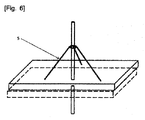
図6は設置施設支持台5に対する模式図であって、工程運転時に発生する土壌沈下による浄化施設物の倒れる可能性や破損を予防するために、発熱棒3−1および抽出管井2−4と結合して安定性を確保する。
図7は地下水の水位調節システムに対する模式図であって、埋没地外部に観測井戸2−5と地下水抽出管井2−4−1を設置して、酸化工程時の埋没地外部の地下水流入による工程効率低下を防止するために埋没地内部の水位が発熱棒と接しないように持続的に調節する。
FIG. 6 is a schematic diagram for the
FIG. 7 is a schematic diagram for a groundwater level control system, in which an observation well 2-5 and a groundwater extraction pipe well 2-4-1 are installed outside the burial site, and the process is based on the inflow of groundwater outside the burial site during the oxidation process. In order to prevent a decrease in efficiency, the water level inside the buried area is continuously adjusted so that it does not contact the heating rod.
上記では本発明の一態様による原位置地中酸化(燃焼)による家畜埋立地の安定化処理システムについて説明し、次は前記システムを用いる本発明による原位置地中酸化(燃焼)による家畜埋立地の安定化処理方法について説明する。
図8は本発明による原位置地中酸化(燃焼)による家畜埋立地の安定化処理工程図を示す。
In the above, the stabilization processing system for livestock landfill by in-situ oxidation (combustion) according to one aspect of the present invention is described, and next, livestock landfill by in-situ oxidation (combustion) according to the present invention using the system The stabilization processing method will be described.
FIG. 8 shows a stabilization process diagram of livestock landfill by in-situ oxidation (combustion) according to the present invention.
図8に例示されたように、本発明による原位置地中酸化(燃焼)による家畜埋立地の安定化処理方法は、家畜埋立地に設置された発熱棒を稼働すると同時に、発熱棒上端に形成された空気注入口を通じて空気または微量の純粋酸素を注入し、別途に家畜埋立地内に空気を吸入して、熱伝達が地下土壌媒質内で効果的に行われるようにする改善技術であって、前処理段階;温度上昇段階;乾燥段階;燃焼段階;熱安定化段階;からなる。 As illustrated in FIG. 8, the method for stabilizing livestock landfill by in-situ oxidation (combustion) according to the present invention operates the heating rod installed in the livestock landfill and at the same time forms the top of the heating rod. An improved technology for injecting air or a small amount of pure oxygen through the air inlet and separately sucking air into the livestock landfill so that heat transfer is effectively performed in the underground soil medium, A pretreatment stage; a temperature rise stage; a drying stage; a combustion stage; a thermal stabilization stage.
これを段階別に具体的に説明すれば、前処理段階では地中燃焼工程の効率を高めるために地下水位を低くし、埋め立てられた動物斃死体からの浸出水を処理し、温度上昇段階では発熱棒を稼働しながら空気を注入し、前記動物斃死体が埋め立てられている付近に発熱棒を通じて持続的に熱を供給して、土壌空隙水および斃死体が保有している水分を乾燥させることができる条件(〜100℃)を形成し、乾燥段階では100℃を維持しながら、前記土壌空隙水および斃死体が保有している水分を蒸発させることによって効果的に燃焼が起こるようにし、燃焼段階では前記乾燥された動物斃死体が周辺に吸入される空気中に含まれている酸素または燃焼効率を高めるための微量の純粋酸素注入を通じて200〜850℃範囲で燃焼され、動物斃死体自体が熱源になってその周辺に熱が拡散するようにし、最後に熱安定化段階では100〜250℃で動物斃死体が完全に燃焼した後、燃焼物質がなくなることによって燃焼が終了するようにする。できるだけ、前記各段階の間では燃焼ガスを収集排出して酸化処理するようにすることが良い。前記燃焼段階と熱安定化段階の間で微量のCOとNOx、SOxが排出される。
To explain this step by step, the groundwater level is lowered to increase the efficiency of the underground combustion process in the pretreatment stage, leachate from landfilled animal carcasses is treated, and heat is generated in the temperature rise stage. Air is injected while the rod is in operation, and heat is continuously supplied through the heating rod in the vicinity where the animal carcass is buried to dry the soil pore water and the water held by the carcass. Forming a condition (˜100 ° C.), and maintaining the temperature at 100 ° C. in the drying stage, allowing the soil pore water and the water contained in the carcass to evaporate to effectively burn, and the combustion stage Then, the dried animal corpse is burned in the range of 200 to 850 ° C. through the injection of oxygen contained in the air sucked into the surrounding area or a small amount of pure oxygen to increase the combustion efficiency. The body itself becomes a heat source so that heat is diffused around it. Finally, in the heat stabilization stage, after the animal carcass is completely burned at 100 to 250 ° C., the combustion is terminated by the disappearance of the combustion substance. To. As much as possible, it is preferable to collect and discharge the combustion gas between each of the stages and oxidize it. Trace amounts of CO, NOx, and SOx are discharged between the combustion stage and the thermal stabilization stage.
図9はヒーター電源を入れて、発熱棒表面温度を500〜700℃で維持した状態で空気を注入して、発熱棒近所で熱源が十分に形成された後にほぼ20時間経過後に空気吸入を実施した場合の地中内熱処理効果(温度上昇)を示すグラフであって、(a)は発熱棒から40cm離れた位置、(b)は60cm離れた位置での熱処理効果を示し、空気注入(発熱棒内)と空気吸入(地中埋立地内)を併行した時、空気注入のみを行った時よりもさらに温度が急速に上昇して、地中に埋め立てられた動物斃死体を乾燥燃焼させて、酸化(燃焼)効果を極大化させることができるのを示す。
In Fig. 9, the heater power is turned on, air is injected with the surface temperature of the heating rod maintained at 500 to 700 ° C, and air is inhaled after about 20 hours have passed since the heat source is sufficiently formed in the vicinity of the heating rod. It is a graph which shows the underground heat treatment effect (temperature rise) at the time of carrying out, (a) shows the heat treatment effect in the
図10は本発明の処理方法、即ち、家畜埋立地に設置された発熱棒を稼働すると同時に、発熱棒上端に形成された空気注入口を通じて空気を注入し、別途に家畜埋立地内に空気を吸入して、熱伝達が地下土壌媒質内で効果的に行われるようにした技術を利用して、発熱棒表面温度を500〜700℃で維持した状態で4日間システムを運転して温度を測定した結果を示すグラフであって、(a)は発熱棒から50cm離れた位置の結果であり、(b)は80cm離れた位置の結果を示し、発熱棒から距離が近いほど時間が経過するにつれて温度が早く上昇して、乾燥、燃焼および熱安定化段階が円滑に行われることが分かる。特に、発熱棒から50cm離れた位置では30時間経過後、250℃以上に上昇して、燃焼が活発に行われた後、70時間が経過しながら最終熱安定化段階に入ることが確認される。従って、経済的側面を考慮してみる時、各燃焼範囲が発熱棒から40〜80cm程度、つまり、互いに隣接した両側発熱棒の間ができるたけ80〜160cmで離隔した燃焼範囲を有することができるように配置することが酸化(燃焼)処理に適当である。
FIG. 10 shows a processing method according to the present invention, that is, the heating rod installed in the livestock landfill is operated, and at the same time, air is injected through the air inlet formed at the upper end of the heating rod, and the air is separately sucked into the livestock landfill. Then, the temperature was measured by operating the system for 4 days while maintaining the surface temperature of the heating rod at 500 to 700 ° C. using the technology that effectively performed heat transfer in the underground soil medium. It is a graph which shows a result, (a) is a result of the
以上のように本発明を実施例を参考にして説明したが、これは本発明を説明するためのものにすぎず、本発明が属する技術分野における通常の知識を有する者であれば、発明の詳細な説明から多様な変形または均等な実施例が可能であるということを理解することができる。従って、本発明の真正の権利範囲は特許請求の範囲の技術的な思想によって決定されなければならない。 As described above, the present invention has been described with reference to the embodiments. However, this is only for explaining the present invention, and any person having ordinary knowledge in the technical field to which the present invention belongs can be used. It can be understood from the detailed description that various modifications or equivalent embodiments are possible. Therefore, the true scope of right of the present invention must be determined by the technical concept of the claims.
本発明の原位置地中酸化燃焼による家畜埋立地の安定化処理技術は、浸出水排出源を根本的に除去することによって浸出水流出による地下水汚染を防止し、安定的に斃家畜を酸化燃焼させることができるので、長期モニタリングと維持管理が要求される浸出水処理技術および熱炭化による家畜埋立地の安定化処理技術に比べて費用面で経済的であり、既埋没した斃死家畜を焼却するための掘削工程と施設物を必要としないので、掘削時に動員される人力が伝染性ウイルスに露出される問題点などを予防改善することができる。 The livestock landfill stabilization technology by in-situ oxidative combustion of the present invention fundamentally removes leachate discharge sources to prevent groundwater contamination due to leachate spills, and stably oxidizes and burns livestock. Compared to leachate treatment technology that requires long-term monitoring and maintenance, and stabilization treatment technology for livestock landfills by thermal carbonization, incineration of already buried dead animals This eliminates the need for an excavation process and facilities to prevent and improve the problems that human power mobilized during excavation is exposed to infectious viruses.
1:断熱雨水遮水膜
1−1:セラミック繊維
1−2:粘土層
2:浸出水およびガス真空抽出処理装置
2−1:気体液体分離機
2−2:高温殺菌処理機
2−3:真空ポンプ
2−4:抽出管井
2−4−1:埋没地外部地下水の水位調節用抽出管井
2−5:埋没地外部地下水の水位調節用観測井戸
2−6:急速酸化処理機
2−7:凝縮機
2−8:排出装置
3:斃死体酸化(燃焼)処理装置
3−1:発熱棒
3−2:発電機
3−3:外皮
3−4:発熱コイル
3−5:炭素鋼パイプ
3−6:孔
3−7:点火装置
3−8:制御盤(Control Panel)
4:モニタリング装置
5:設置施設支持台
1: Adiabatic rainwater barrier film 1-1: Ceramic fiber 1-2: Clay layer 2: Leached water and gas vacuum extraction treatment device 2-1: Gas liquid separator 2-2: High temperature sterilization treatment device 2-3: Vacuum Pump 2-4: Extraction pipe well 2-4-1: Extraction pipe well for adjusting water level outside buried area 2-5: Observation well for adjusting water level outside buried area 2-6: Rapid oxidation treatment machine 2-7: Condensation Machine 2-8: Discharge device 3: Dead body oxidation (combustion) treatment device 3-1: Heat generation rod 3-2: Generator 3-3: Outer shell 3-4: Heat generation coil 3-5: Carbon steel pipe 3-6 : Hole 3-7: Ignition device 3-8: Control panel (Control Panel)
4: Monitoring device 5: Installation facility support stand
Claims (12)
雨水を遮断するための断熱雨水遮水膜と、
前記動物斃死体が埋立処理されている埋立地内部から浸出水およびガスを真空抽出処理するための浸出水およびガス真空抽出処理装置と、
前記埋立地に設置される複数個の発熱棒を備え、前記埋立処理された動物斃死体を燃焼することによって酸化させる斃死体酸化処理装置と、
該斃死体酸化処理装置の前記発熱棒の各々の地上に突出した部分を安定的に支持するための支柱状の設置施設支持台とを備え、
前記斃死体酸化処理装置は、上端に形成された空気注入口を各々有し処理面積によって複数個設置された前記発熱棒と、該複数個の発熱棒に連結された発電機とを備え、前記空気注入口から前記発熱棒を介して前記埋立地内部に注入された空気と前記発電機からの電気エネルギーとを利用して前記動物斃死体の水分、血液、油分を乾燥させ前記動物斃死体を酸化させるようにしたことを特徴とする原位置地中酸化による家畜埋立地の安定化処理システム。 A system for in situ oxidation treatment of landfilled animal carcasses,
A heat insulating rainwater impervious film for blocking rainwater;
Leached water and gas vacuum extraction treatment device for vacuum extraction treatment of leachate and gas from inside the landfill where the animal carcasses are being landfilled,
A carcass oxidation treatment apparatus comprising a plurality of heating rods installed in the landfill, and oxidizing the burned animal carcass by burning the landfill;
A column-shaped installation facility support base for stably supporting a portion of the heating rod of the carcass oxidation processing apparatus that protrudes above the ground,
The carcass oxidation processing apparatus includes the heating rods each having an air inlet formed at an upper end and installed in a plurality of processing areas, and a generator connected to the plurality of heating rods, The animal carcass is dried by drying the water, blood, and oil of the animal carcass using air injected from the air inlet through the heating rod into the landfill and electrical energy from the generator. A stabilization system for livestock landfills by in-situ ground oxidation, characterized by oxidation.
前記埋立地に設置された多数の抽出管井と、
前記浸出水および前記ガスを、前記多数の抽出管井を介して前記埋立地内部から汲み上げる真空ポンプと、
該真空ポンプによって汲み上げられた前記浸出水と前記ガスとを互いに分離する気体液体分離機と、
該気体液体分離機によって分離された前記浸出水を高温殺菌処理する高温殺菌処理機と、
前記気体液体分離機によって分離された前記ガスを完全燃焼する急速酸化処理機と、
該急速酸化処理機によって完全燃焼された前記ガスを排出する排出装置とを備えることを特徴とする、請求項1に記載の原位置地中酸化による家畜埋立地の安定化処理システム。 The leachate and gas vacuum extraction treatment device is:
A number of extraction wells installed in the landfill;
A vacuum pump for pumping the leachate and gas from the landfill through the multiple extraction wells;
A gas-liquid separator that separates the leachate and the gas pumped by the vacuum pump from each other;
A high-temperature sterilization treatment machine for high-temperature sterilization treatment of the leachate separated by the gas-liquid separator;
A rapid oxidation processor that completely burns the gas separated by the gas-liquid separator;
The livestock landfill stabilization treatment system according to claim 1, further comprising: a discharge device that discharges the gas completely burned by the rapid oxidation treatment machine.
発熱棒の稼働と同時に発熱棒の上端に提供された空気注入口を通して空気を注入した後、発熱棒内で加熱された高温の空気が地下媒質の空隙を通して伝達されて動物斃死体を酸化させることを特徴とする、請求項1に記載の原位置地中酸化による家畜埋立地の安定化処理システム。 The carcass oxidation treatment apparatus further includes a control panel for adjusting the temperature of the heating rod,
After injecting air through the air inlet provided at the upper end of the heating rod simultaneously with the operation of the heating rod, hot air heated in the heating rod is transmitted through the void in the underground medium to oxidize the animal carcass The stabilization processing system of the livestock landfill by the in-situ underground oxidation of Claim 1 characterized by these.
前記動物斃死体が埋立処理されている埋立地に設置された多数の発熱棒を稼働しながら該発熱棒を介して前記埋立地内部に空気を注入し、前記動物斃死体が埋め立てられている付近に前記発熱棒を通じて持続的に熱を供給して、土壌空隙水および動物斃死体が保有している水分を乾燥させることができるように前記動物斃死体が埋め立てられている付近を加熱する温度上昇ステップと、
前記発熱棒を介して前記埋立地内部に空気を注入し続けながら、約100℃を維持した状態で続けて熱を加えて、前記土壌空隙水および動物斃死体が保有している水分を蒸発させることによって効果的に燃焼が起こるようにする乾燥ステップと、
前記発熱棒を介して前記埋立地内部に空気を注入し続けながら、さらに別個に前記動物斃死体の周辺に空気を吸入するか、または、燃焼効率を一層高めるための微量の純粋酸素を前記発熱棒を介して注入し、前記乾燥された動物斃死体が、周辺に吸入される空気中に含まれている酸素または微量の純粋酸素注入を通じて200〜850℃範囲で燃焼され、動物斃死体自体が熱源になってその周辺に熱が拡散するようにする燃焼ステップと、
動物斃死体が完全に燃焼された後、燃焼物質がなくなりながら、100〜250℃で燃焼が終了する熱安定化ステップと
から構成されたことを特徴とする原位置地中酸化による家畜埋立地の安定化処理方法。 In order to increase the efficiency of the underground oxidation process, leachate and groundwater from landfilled animal carcasses are extracted from the ground to the ground to lower the groundwater level, and the extracted leachate is subjected to high-temperature sterilization treatment. A pre-processing step;
While operating a large number of heating rods installed in a landfill where the animal carcass has been landfilled , air is injected into the landfill through the heat generating rod, and the vicinity where the animal carcass is buried The temperature rise to heat the area where the animal carcass is buried so that the soil pore water and the water held by the animal carcass can be dried by supplying heat continuously through the heating rod Steps,
While continuously injecting air into the landfill through the heating rod, heat is continuously applied while maintaining a temperature of about 100 ° C. to evaporate the water held by the soil pore water and the animal carcass. A drying step that effectively causes combustion, and
While continuously injecting air into the landfill through the heating rod, air is separately sucked into the vicinity of the animal carcass, or a small amount of pure oxygen for further improving the combustion efficiency is generated in the heat generation. bar was injected through the dry animal mortality body, or oxygen contained in the air drawn into the periphery is combusted at 200 to 850 ° C. range throughout pure oxygen injection fine amount, animal mortality body A combustion step that itself becomes a heat source and allows heat to diffuse around it,
After the animal carcass has been completely burned, it is composed of a heat stabilization step in which combustion ends at 100 to 250 ° C. while the burning material is lost, Stabilization method.
The method for stabilizing livestock landfill by in situ oxidation according to claim 10, wherein the plurality of heating rods are arranged in a range of 80 to 160 cm apart from each other.
Applications Claiming Priority (3)
| Application Number | Priority Date | Filing Date | Title |
|---|---|---|---|
| KR10-2011-0031994 | 2011-04-07 | ||
| KR20110031994A KR101097742B1 (en) | 2011-04-07 | 2011-04-07 | Management system and method for stabilizing livestock reclaimed ground by in - site oxidation |
| PCT/KR2012/001774 WO2012138061A1 (en) | 2011-04-07 | 2012-03-12 | Processing system and method for stabilizing livestock reclaimed ground by on-site underground oxidation (combustion) |
Publications (2)
| Publication Number | Publication Date |
|---|---|
| JP2014504206A JP2014504206A (en) | 2014-02-20 |
| JP5771282B2 true JP5771282B2 (en) | 2015-08-26 |
Family
ID=45506807
Family Applications (1)
| Application Number | Title | Priority Date | Filing Date |
|---|---|---|---|
| JP2013543117A Expired - Fee Related JP5771282B2 (en) | 2011-04-07 | 2012-03-12 | System and method for stabilizing livestock landfill by in situ oxidation (combustion) |
Country Status (4)
| Country | Link |
|---|---|
| EP (1) | EP2696141B1 (en) |
| JP (1) | JP5771282B2 (en) |
| KR (1) | KR101097742B1 (en) |
| WO (1) | WO2012138061A1 (en) |
Families Citing this family (5)
| Publication number | Priority date | Publication date | Assignee | Title |
|---|---|---|---|---|
| KR102069787B1 (en) | 2018-04-09 | 2020-01-28 | 이성기 | Bacterial consortium for accelerating decomposition from stamped out animal |
| CN110762532B (en) * | 2019-11-08 | 2021-05-11 | 浙江天翔环保设备有限公司 | A refine oil and draw equipment for incinerating spoil |
| KR102348481B1 (en) * | 2020-02-13 | 2022-01-07 | 동아대학교 산학협력단 | Purification system for animal carcass disposal sites using oxygen supersaturated leachate cycle |
| CN111675559A (en) * | 2020-05-29 | 2020-09-18 | 广东益康生环保设备有限公司 | Complete equipment and method for treating solid waste in farm |
| CN114440227A (en) * | 2022-03-11 | 2022-05-06 | 江苏碳峰蓝节能科技有限公司 | Belt type in-situ oxidation device |
Family Cites Families (14)
| Publication number | Priority date | Publication date | Assignee | Title |
|---|---|---|---|---|
| JPH04118414A (en) * | 1990-09-10 | 1992-04-20 | Nippon Sogo Kenkyusho:Kk | Field solidification treatment of soil with waste refuse buried in |
| KR100332003B1 (en) * | 1999-07-22 | 2002-04-10 | 고학봉 | Apparatus for treating landfill leachate by using heat source of landfill gas |
| US6749368B2 (en) * | 2000-09-05 | 2004-06-15 | Daniel B. Stephens & Associates, Inc. | Design, monitoring and control of soil carburetors for degradation of volatile compounds |
| KR100478403B1 (en) * | 2000-11-13 | 2005-03-23 | 이엔브이이십일(주) | Landfill structure using concept of multi-layered reactors and method for operating the same |
| JP2002239493A (en) * | 2001-02-16 | 2002-08-27 | Goro Takagi | Method for treating water generated at final disposal site |
| KR100397764B1 (en) | 2001-04-24 | 2003-09-19 | 아름다운 환경건설(주) | Restitutive apparatus for polluted soil driving by vehicles |
| JP4346268B2 (en) | 2001-12-12 | 2009-10-21 | 三井造船株式会社 | Waste treatment apparatus and waste treatment method |
| JP2003236496A (en) * | 2002-02-13 | 2003-08-26 | Oshima Shipbuilding Co Ltd | Treatment system for livestock byproduct and ceramic material comprising treated residue |
| JP2005319456A (en) * | 2004-04-07 | 2005-11-17 | Nishida Kosan:Kk | Stabilization accelerating method for waste landfill disposal site |
| KR100440403B1 (en) * | 2004-05-04 | 2004-07-14 | 주식회사 지화이브 | Waste carbonizing disposer |
| KR100862377B1 (en) | 2007-08-20 | 2008-10-13 | 대한민국(관리부서:농촌진흥청) | Heating animal corpse handling device using vacuum |
| KR101469535B1 (en) * | 2008-06-02 | 2014-12-08 | 농업법인우리생명 (주) | A deserted domestic animal land reclamation revival purification management method |
| KR20100082131A (en) * | 2009-01-08 | 2010-07-16 | 위승용 | System leachate-preventive , odor , virus remove for reclamation of avian influenza bird |
| KR101035500B1 (en) | 2009-08-12 | 2011-05-20 | (주)제이브이엠 | Terminal for remote verify of condition in auto wrapping pill |
-
2011
- 2011-04-07 KR KR20110031994A patent/KR101097742B1/en active IP Right Grant
-
2012
- 2012-03-12 WO PCT/KR2012/001774 patent/WO2012138061A1/en active Application Filing
- 2012-03-12 JP JP2013543117A patent/JP5771282B2/en not_active Expired - Fee Related
- 2012-03-12 EP EP12768105.4A patent/EP2696141B1/en not_active Not-in-force
Also Published As
| Publication number | Publication date |
|---|---|
| EP2696141A4 (en) | 2014-10-15 |
| EP2696141A1 (en) | 2014-02-12 |
| EP2696141B1 (en) | 2018-11-28 |
| WO2012138061A1 (en) | 2012-10-11 |
| JP2014504206A (en) | 2014-02-20 |
| KR101097742B1 (en) | 2011-12-23 |
Similar Documents
| Publication | Publication Date | Title |
|---|---|---|
| JP5771282B2 (en) | System and method for stabilizing livestock landfill by in situ oxidation (combustion) | |
| US5251700A (en) | Well casing providing directional flow of injection fluids | |
| CA2032131C (en) | In situ soil decontamination method and apparatus | |
| US5011329A (en) | In situ soil decontamination method and apparatus | |
| CA2569621C (en) | Method and system for cleaning a soil containing contaminants | |
| WO2013008338A1 (en) | Ground sterilizing device and ground sterilizing method | |
| KR20170059735A (en) | Landfill Gas Treatment and Heat Energy Utilization System in aerobic Solid Waste Lnadfill | |
| KR101260653B1 (en) | Portable type incineration apparatus | |
| KR20190105965A (en) | Carbonization incinerator of livestock body | |
| JP2010058103A (en) | Apparatus for pyrolyzing organic substance by magnetic pneumatic means | |
| KR101131340B1 (en) | Management system for stabilizing livestock reclaimed land through heat carbonization of original site | |
| KR101381245B1 (en) | Disposal apparatus of dead animal body | |
| KR101849886B1 (en) | Eco-friendly stall having a function of removing bad smell and soundfroof | |
| JP3389966B2 (en) | Method and apparatus for separating and removing harmful substances | |
| KR20170026048A (en) | Landfill Gas Treatment and Heat Energy Utilization System in aerobic Solid Waste Lnadfill | |
| KR20220063019A (en) | System for disposaling animals without bad smell | |
| KR101227593B1 (en) | Crushing and Drying Apparatus | |
| KR20120014980A (en) | Eco friendly cremating method | |
| KR102424614B1 (en) | System for treating animal carcass | |
| KR102199170B1 (en) | THE PERISH LIVESTOCK BURIAL TANK capable of deodorant | |
| KR102514281B1 (en) | Livestock body storage tank using precast concrete | |
| JP2004305898A (en) | Soil cleaning method | |
| KR101345398B1 (en) | System and method for ground heat treatment of original site | |
| KR20140093041A (en) | Perish livestock treater | |
| JP2001157898A (en) | Method for treating waste water from waste disposal plant |
Legal Events
| Date | Code | Title | Description |
|---|---|---|---|
| A977 | Report on retrieval |
Free format text: JAPANESE INTERMEDIATE CODE: A971007 Effective date: 20140418 |
|
| A131 | Notification of reasons for refusal |
Free format text: JAPANESE INTERMEDIATE CODE: A131 Effective date: 20140527 |
|
| A521 | Request for written amendment filed |
Free format text: JAPANESE INTERMEDIATE CODE: A523 Effective date: 20140812 |
|
| A131 | Notification of reasons for refusal |
Free format text: JAPANESE INTERMEDIATE CODE: A131 Effective date: 20141007 |
|
| A521 | Request for written amendment filed |
Free format text: JAPANESE INTERMEDIATE CODE: A523 Effective date: 20141219 |
|
| TRDD | Decision of grant or rejection written | ||
| A01 | Written decision to grant a patent or to grant a registration (utility model) |
Free format text: JAPANESE INTERMEDIATE CODE: A01 Effective date: 20150616 |
|
| A61 | First payment of annual fees (during grant procedure) |
Free format text: JAPANESE INTERMEDIATE CODE: A61 Effective date: 20150626 |
|
| R150 | Certificate of patent or registration of utility model |
Ref document number: 5771282 Country of ref document: JP Free format text: JAPANESE INTERMEDIATE CODE: R150 |
|
| R250 | Receipt of annual fees |
Free format text: JAPANESE INTERMEDIATE CODE: R250 |
|
| R250 | Receipt of annual fees |
Free format text: JAPANESE INTERMEDIATE CODE: R250 |
|
| R250 | Receipt of annual fees |
Free format text: JAPANESE INTERMEDIATE CODE: R250 |
|
| R250 | Receipt of annual fees |
Free format text: JAPANESE INTERMEDIATE CODE: R250 |
|
| R250 | Receipt of annual fees |
Free format text: JAPANESE INTERMEDIATE CODE: R250 |
|
| LAPS | Cancellation because of no payment of annual fees |