EP2696080B1 - Electro-hydraulic control - Google Patents
Electro-hydraulic control Download PDFInfo
- Publication number
- EP2696080B1 EP2696080B1 EP12179874.8A EP12179874A EP2696080B1 EP 2696080 B1 EP2696080 B1 EP 2696080B1 EP 12179874 A EP12179874 A EP 12179874A EP 2696080 B1 EP2696080 B1 EP 2696080B1
- Authority
- EP
- European Patent Office
- Prior art keywords
- valve
- pilot pressure
- control
- proportional
- valves
- Prior art date
- Legal status (The legal status is an assumption and is not a legal conclusion. Google has not performed a legal analysis and makes no representation as to the accuracy of the status listed.)
- Not-in-force
Links
Images


Classifications
-
- F—MECHANICAL ENGINEERING; LIGHTING; HEATING; WEAPONS; BLASTING
- F15—FLUID-PRESSURE ACTUATORS; HYDRAULICS OR PNEUMATICS IN GENERAL
- F15B—SYSTEMS ACTING BY MEANS OF FLUIDS IN GENERAL; FLUID-PRESSURE ACTUATORS, e.g. SERVOMOTORS; DETAILS OF FLUID-PRESSURE SYSTEMS, NOT OTHERWISE PROVIDED FOR
- F15B11/00—Servomotor systems without provision for follow-up action; Circuits therefor
- F15B11/003—Systems with load-holding valves
-
- F—MECHANICAL ENGINEERING; LIGHTING; HEATING; WEAPONS; BLASTING
- F15—FLUID-PRESSURE ACTUATORS; HYDRAULICS OR PNEUMATICS IN GENERAL
- F15B—SYSTEMS ACTING BY MEANS OF FLUIDS IN GENERAL; FLUID-PRESSURE ACTUATORS, e.g. SERVOMOTORS; DETAILS OF FLUID-PRESSURE SYSTEMS, NOT OTHERWISE PROVIDED FOR
- F15B2211/00—Circuits for servomotor systems
- F15B2211/30—Directional control
- F15B2211/31—Directional control characterised by the positions of the valve element
- F15B2211/3122—Special positions other than the pump port being connected to working ports or the working ports being connected to the return line
- F15B2211/3127—Floating position connecting the working ports and the return line
-
- F—MECHANICAL ENGINEERING; LIGHTING; HEATING; WEAPONS; BLASTING
- F15—FLUID-PRESSURE ACTUATORS; HYDRAULICS OR PNEUMATICS IN GENERAL
- F15B—SYSTEMS ACTING BY MEANS OF FLUIDS IN GENERAL; FLUID-PRESSURE ACTUATORS, e.g. SERVOMOTORS; DETAILS OF FLUID-PRESSURE SYSTEMS, NOT OTHERWISE PROVIDED FOR
- F15B2211/00—Circuits for servomotor systems
- F15B2211/50—Pressure control
- F15B2211/505—Pressure control characterised by the type of pressure control means
- F15B2211/50563—Pressure control characterised by the type of pressure control means the pressure control means controlling a differential pressure
- F15B2211/50581—Pressure control characterised by the type of pressure control means the pressure control means controlling a differential pressure using counterbalance valves
- F15B2211/5059—Pressure control characterised by the type of pressure control means the pressure control means controlling a differential pressure using counterbalance valves using double counterbalance valves
-
- F—MECHANICAL ENGINEERING; LIGHTING; HEATING; WEAPONS; BLASTING
- F15—FLUID-PRESSURE ACTUATORS; HYDRAULICS OR PNEUMATICS IN GENERAL
- F15B—SYSTEMS ACTING BY MEANS OF FLUIDS IN GENERAL; FLUID-PRESSURE ACTUATORS, e.g. SERVOMOTORS; DETAILS OF FLUID-PRESSURE SYSTEMS, NOT OTHERWISE PROVIDED FOR
- F15B2211/00—Circuits for servomotor systems
- F15B2211/50—Pressure control
- F15B2211/575—Pilot pressure control
Definitions
- the invention relates to an electro-hydraulic control according to the preamble of patent claim 1.
- EP 1 766 246 A or DE 199 19 014 A known electro-hydraulic control is the directional slide a 4/4-Proportionalwegeschieber, in addition to two control positions (eg lifting and lowering) has a zero position in which the hydraulic consumer is hydraulically blocked (both working lines shut off to the return and separated from the pressure source), and a fourth position , in which both working lines are connected to the return (floating position).
- the load-holding valves are opened simultaneously and fully in the floating position or at the transition to the control pressure supply via the 4/4 proportional directional slide.
- an attachment excavated by means of the hydraulic consumer then the attachment to follow in the floating position on the ground resting bumps must first be lowered slowly enough by adjusting the lowering control position of the 4/4-proportional directional slide on the ground before the float position is adjusted. This is then the responsibility of the driver. If the lowering control position is overrun too quickly to lower, then the attachment falls hard on the ground.
- an attachment in the floating position can be excavated when jumping over a survey and made to jump, after which it hits hard on the ground, because just in the floating position both load-holding valves are fully open and the hydraulic consumer has no significant resistance.
- a distinctive bottom elevation bring the attachment to jump and hit, because in a control position of the 4/4-proportional directional slider, for example, a certain contact pressure is set on the ground, since the load-holding valves are fully opened.
- Out EP 2 466 153 A is an electro-hydraulic control is known
- the multi-way multi-position directional slide is a 4/3-proportional valve with pressure pilot controls, in which the floating position without fourth slide position is adjustable in that both pressure piloting their proportional solenoids are energized simultaneously and the same, causing the slide his to return open zero position occupies, and at the same time the pilot pressures are transmitted to the two load-holding valves to control this, so that the working lines are connected via the proportional slide with the return.
- the zero position of the slide also becomes hydraulic blocking of the hydraulic consumer used. Then the two proportional solenoids are not energized, so that there are no pilot pressures and the load-holding valves remain in their shut-off positions and block the working lines.
- valve assembly with locking function
- said valve assembly includes a multi-way proportional position proportional slide a 4/4-proportional valve having a zero position between two control positions (lifting / lowering), in which the working lines of the hydraulic consumer from the pressure source and the return are separated and thus the hydraulic consumer is hydraulically blocked.
- a fourth position is provided as a switching position, which is adjustable from the lowered position, and in which both working lines are separated from the pressure source and connected to the return. To switch from the zero position to the floating position, the lowering position must first be overrun.
- 4/4-Proportionalwegeschieber are structurally very complex and expensive, taking into account that usually up to six or eight hydro consumers can share a common pressure source, so that a correspondingly large number of 4/4-proportional valve is needed.
- the pilot control circuits of the two load-holding valves are protected by blocking valves, each of which is held by the pilot circuit of a load-holding valve by control pressure and parallel thereto by a closing spring in a leak-free shut-off when the load-holding valve must be kept controlled.
- Each check valve is switched by control pressure from a pressure in the control position of the control line in the direction of a passage position to allow the control of the load-holding valve.
- both control lines are pressurized, and thus placed both check valves in their passage positions, so that both load-holding valves are turned on.
- the two, monitored by the slide control lines are each permanently connected via a drain throttle with a return line.
- the discharge throttles have no influence on the opening behavior of the load-holding valves, since they act only on the Auf Kunststoffier the check valves and isolated from the pilot circuit of the load-holding valves.
- Out EP 1 528 264 A1 is a load-lowering control valve with Pilotvor facedung known, wherein a pilot valve element for damping purposes in the pilot circuit, a throttle and a gas pressure accumulator are assigned.
- Out EP 0 464 305 A1 is a hydraulic control device with a 4/3-way slide and arranged in only one working line of a double-acting hydraulic consumer load holding valve known. This load-holding valve is opened from the other working line via a control line containing a hydraulic damping device. A floating position of the hydraulic consumer is not adjustable.
- EP 1 927 759 A1 is a double check valve with a floating function known, which is similar operable as the load-holding valves in the EP 2 466 153 A known electro-hydraulic control.
- the double check valve acts as two load-holding valves in the working lines of the double-acting hydraulic consumer, for the direction and speed control of a 4/3-slide is provided with magnetic actuation. In the open zero position of this 4/3-slide both working lines are isolated from the pressure source and connected to the return. However, as long as the double check valve maintains its blocking positions, the hydraulic consumer remains hydraulically blocked in the zero position of the 4/3 slide. Only when the double check valve is acted upon by control pressure from a control pressure source and hydraulically unlocked, resulting in the zero position, a floating position of the hydraulic consumer. The hydraulic release of the double check valve takes place without any damping.
- the invention has for its object to improve an electro-hydraulic control of the type mentioned in that critical or the desired work result impairing movements of a load controlled by the hydraulic consumer can be avoided. Part of the task is thereby, at least in the floating position comfortable, e.g. automatically to be able to act on load movements.
- the damping device is provided in a 4/3-proportional valve with pressure pilot controls and, for example, "electrical" floating position in the pilot circuit of the load-holding valves. Because to be controlled. However, this type of slide is much cheaper and smaller as a four position proportional slider with separate float position. The floating position is set in the "open" zero position by controlling the load holding valves. There are two options here. Both pressure pilot controls are actuated identically and simultaneously via their proportional solenoids, and the pilot pressure is regulated via the damper device to the control sides of the load-holding valves.
- control pressure from the control pressure supply can be used directly via the retarding damper device to control the load holding valves, for example, when the 4/3-proportional directional slide is in its zero position, which it holds by spring force, the proportional solenoid then not necessarily energized at the same time will need, although the proportional magnets can then participate regulate.
- the incorporated in the pilot control damping device ensures at least on the transition to or from and / or during the occupied floating position that load movements are damped in a predetermined or controllable manner.
- the float position for example, without first having to visit the sink control position can be set or turned off very quickly, a load movement occurring is damped and takes place with a time delay which avoids critical states of motion or impairment of a desired result of work by the hydraulic consumer moving implements excludes.
- the damping device can even be used to exclude undesired load movements in control positions of the 4/3 proportional slider, for example a mounted on the ground with a predetermined contact pressure, when it has to negotiate a prominent ground elevation, and in similar situations.
- certain operations of the hydraulic consumer in the electrohydraulic control can be quickly and directly adjusted, but the design is monitored via the damper to prevent damage or deterioration of work or damage to the attachment.
- the damping is set firmly, it comes in each case in a predetermined manner to the effect in which the load-holding valves are controlled controlled. If you work with variable damping, then the damping can be adapted to the circumstances and adjusted, for example, as needed. This is done for example by pressing a pressure switch or with a program routine of an electronic control, so that an operator does not need to worry about a load moved by the hydraulic consumer, eg under the load itself, is controlled slowly enough.
- the load holding valves is thus assigned an additional throttle function by the damping device.
- At least one nozzle is provided in the pilot circuit.
- the pressurization to Open control of at least one load-holding valve made with a time delay, ie the load-holding valve slowly and / or only partially turned on.
- variable damping is performed proportionally across the damper using the pressures generated in the pressure pilot controls of the 4/3 proportional directional damper. This means that although the damping device monitors the time delay of the pressurization when controlling at least one load-holding valve, but an additional influence is also possible because the proportional magnets in the zero position, although equal to each other but more or less energized. This alternative is useful if the float position (control of the load-holding valves in the zero position) is adjusted by picking up the pressures of the pressure pilot control of the 4/3 proportional directional slide.
- the damping device for the purpose of variable damping between the control pressure supply or the pressure pilot, the return, and the Auf Kunststoffbloblo the load-holding valves, a 3/2-proportional pressure control valve or a 3/2-way black / white solenoid valve, preferably at The load-holding valves side facing away from two shuttle valves and / or at least one check valve pair of two opposing check valves.
- the 3/2-way proportional pressure control valve allows, as needed, a variable attenuationmother horrn.
- the 3/2-way black / white magnetic switching valve allows influencing the damping in the control or Zu Kunststoffung the load-holding valves by this valve from the tapped from the control pressure supply or pressure piloting control pressure pressure fluid to the return leaves and so on the way Delay nozzle acts.
- the delay can be controlled very sensitively variable, for example by reducing the tapped from the control pressure supply or the pressure pilot control pressure on the control side of at least one load-holding valve.
- a, preferably elektroproportionales, throttle valve is provided between the return and connected to the control pressure supply or Druckvor Kunststoffmaschineungen control sides of the load-holding valves, preferably on the side facing away from the load-holding valves of two shuttle valves and / or at least one check valve pair.
- the delay can be modulated via the electro-proportional adjustable throttle valve.
- the electrohydraulic control has a proportional pressure control section to which the working lines of the hydraulic consumer are connected are in addition to the pressure control via the 4/3-proportional valve pressures in the working lines to regulate electro-proportional, similar to a conventional secondary pressure limitation. If the pilot circuit downstream of the pressure control section and this is connected to the return, the pilot circuit or at least a part on a control side of a load-holding valve via the pressure control section to the return can be relieved to vary the damping. This may be expedient in particular in the floating position of the 4/3-proportional directional slide, since then the working lines are depressurized.
- the fixed damping or variable damping is the same for both load-holding valves.
- both to and from the hydraulic consumer flowing pressure medium is throttled to achieve the damping.
- the fixed or variable damping may be different for both load-holding valves, or may be different, or only on a load-holding valve, e.g. used for lowering.
- the fixed or variable damping is brought about the damping device even in at least one control position of the 4/3-proportional slider outside the zero position to action. This can be done for example in a control position in which the hydraulic consumer holds an attachment with a predetermined pressure on the ground, which bumps could cause jumping of the attachment, which is eliminated or minimized by the damping.
- the damping device allows a further improvement of the operating behavior and an effect on load movements.
- the load-holding valves are connected so that in two control positions of the 4/3-proportional valve (eg lifting and lowering) arranged in the one working line load-holding valve from the other working line via a connected to the pilot control line with Jerusalem Grahambar from the working line control pressure is auf mortbar ,
- the control lines to shuttle valves or check valve pairs in the pilot circuit.
- the shuttle valves or check valve pairs ensure that in the control positions, the pressure from the working lines is brought to the control sides, while in the floating position or zero position, the control pressures of the pressure pilot control or the control pressure of the control pressure supply is brought to the respective control side, and the damping device is effective.
- each nozzle is arranged on the control side of the load-holding valve in the pilot circuit, wherein the nozzles are sized the same or different.
- At least one return flow damping system can be provided in the working lines and / or on the control sides of the load-holding valves.
- This backflow-damping system consists for example of a non-return valve blocking in the outflow direction, which is bypassed in a bypass line of a nozzle which throttles in the return flow direction.
- Each load-holding valve is, for example, a bypass valve which can be bypassed by a check valve in the inflow direction to the hydraulic consumer and which is spring-loaded on the supply side upstream of the working line and additionally pressure-controlled on the upstream side from the working line downstream of the check valve and from the pilot circuit.
- the load-holding valve a 2/2-way pressure control valve with integrated check valve (locks in the outflow from the hydraulic consumer), the 2/2-way pressure control valve acted upon by spring force to a backflow blocking position and pressure controlled controlled passage positions from the pilot circuit becomes.
- the electrohydraulic control is expedient part of an electronic hoist control, as is customary on mobile work vehicles, which are equipped with at least one attachment or equippable.
- work vehicles are snow plows, snow grooming vehicles, agricultural machines such as tractors, road maintenance machines, or tillage vehicles.
- the damping device which monitors at least the transition to or from the floating position and / or the floating position to avoid critical movements of an attachment, can be activated either permanently or at the touch of a button.
- the different embodiments of the electro-hydraulic control S in the Fig. 1 to 11 can be part of an electronic hoist control EHR (not shown in detail) Fig. 1 ), as used in different mobile working equipment.
- EHR electronic hoist control
- electrohydraulic controls may find use in other areas of high pressure mobile or stationary hydraulics, useful for at least minimizing critical load movements, without the need for an operator of the electrohydraulic controller to necessarily care.
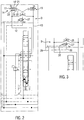
- An electro-hydraulic control S for example, as part of an electrohydraulic hoist control EHR is supplied by a pressure source in a pressure line 1 and is connected to a return line 2.
- a control pressure supply not shown, is connected to a control pressure line 3, while a further tank line 3 'leads to a tank, for example, the control pressure supply.
- Another control line 4 is connected to a load pressure signal circuit LS.
- the electrohydraulic control S serves to actuate a double-acting hydraulic consumer Z, for example a double-acting hydraulic cylinder, with which a load L can be moved in different directions with precisely adjustable speeds and in each case in certain positions, via a multi-way multi-position directional slide W, which is formed in the embodiment shown as a 4/3-way proportional directional slide with a symbolically indicated spool 5.
- a feed regulator 6 is provided on the pressure side.
- the spool 5 is about Druckvortician 7, 8, for example, each with a pressure reducing valve (not shown), and two proportional magnets 9, 10 movable between a total of three positions, namely a lower control position a, an upper control position b and a zero position O, in the connected Working lines 12, 13 are relieved to return 2.
- a spring assembly 11 helps, for example. to set the middle zero position.
- the pressure pilot controls 7, 8 are connected via a line 31 to the control line 3, and via a line 32 to the tank line 3 '.
- each load-holding valve 14, 15 comprises a check valve 16, which is loaded in the reverse direction by a spring 17, and which is connected to a check valve 20 in a bypass loop is bypassed.
- the check valve 20 blocks in the outflow direction from the hydraulic consumer Z.
- the shut-off valve 16 is also pressure-controlled in the reverse direction from the downstream of the check valve 20 from the working line 12 via a pilot line 19, and at a Aufberichtseite 21 from downstream of the check valve 20 from the working line 12 druckvorteil, as well connected to a pilot control circuit K.
- Each control side 21, 21 'of the load-holding valve 14, 15 is connected to a control line 22, 22' in which in the embodiment shown a respective nozzle 23 or 23 'is provided as part of a damping device D integrated in the pilot control circuit K.
- the nozzles 23, 23 ' can be the same size or different sizes.
- the control lines 22, 22 ' cross over to shuttle valves 24, 24' which are interconnected at a node 26 and to which of the working lines 12, 13 e.g. via filter branching control lines 25, 25 'lead to réelle horruiten the load holding valves 14, 15 in the control positions a, b each cross.
- the pressure medium passes through the check valve 20 the closed shut-off valve 16, while at the same time the pressure from the working line 12 via the control line 25, the shuttle valve 24 and the control line 22 ' Load holding valve 15 auf devist on its control side 21 ', so that the pressure medium from the hydraulic consumer Z can be pushed out via the working line 13.
- Another part of the integrated in the pilot circuit K damping device D is a 3/2-way proportional pressure control valve 27 which is adjustable by a proportional solenoid 28 against spring force from the position shown, in which a return line 29 is connected to the node 26, while a Control line 30, which carries a control pressure is shut off.
- the control line 30 leads to the control line 3, which is connected to the control pressure supply to, for example, provides a control pressure of about 20 to 30 bar substantially constant.
- the zero position O of the 4/3-way proportional directional valve W is used both to a hydraulic blockage of the hydraulic consumer Z in its respective position (holding the load L), as well as for setting a floating position, in both working lines 12, 13 with the return 2 are connected. Only to adjust the floating position are in the zero position O befindlichem proportional directional slide W, the two load-holding valves 14, 15 controlled controlled by the damping device D from the control line 30, for which the proportional solenoid 28 is energized accordingly. In conjunction with the nozzles 22, 23 and the choice of the loading force of the proportional solenoid 28, the load-holding valves 14, 15 are only partially or delayed controlled, so that a movement of the load L takes place with a time delay.
- the load-holding valves then act as brake valves or throttles, which allow the load movement to proceed only with a delay, although the 4/3-way proportional directional slide W is in its zero position and connects both working lines 12, 13 with the return line 2.
- the embodiment of the Fig. 2 is different from that of Fig. 1 by the formation of the load-holding valves 14, 15.
- the other structure and the function correspond to those of the embodiment of Fig. 1 ,
- Fig. 3 indicates a detail variant in which in the pilot circuit, a 3/2-way solenoid valve 27 'between the node 26 on the one hand, and the return line 29 and the control line 30 on the other hand, by a black / white magnet 28' between the two Positions is switchable.
- the nozzles 22, 23 'of the damping device D can provide a fixed damping at a load movement at least in the floating position or the transition to or from the floating position.
- control pressure for controlling the load holding valves 14, 15 differs from that of Fig. 1 to 3 in which Fig. 4 in the zero position O for setting the floating position both proportional magnets 9, 10 are energized equal, so that the pressure pilot controls 7, 8, for example, same pressures lead, which are fed via the control lines 30a and 30b simultaneously in the pilot circuit K. It is crucial that both proportional solenoids 9, 10 are energized simultaneously and the same, so that the slider 5 holds the zero position.
- the control pressures in the control lines 30 a, 30 b can be adjusted by selecting the energization of the proportional magnets 9, 10, although equal to each other, but in different heights.
- the damping device D in Fig. 4 is connected via the shuttle valves 24, 24 'and the control lines 25, 25' to the working lines 12, 13.
- the shuttle valves 24, 24 ' are switched to the positions shown, in which the control pressure in the lines 30 a, 30 b via the control lines 22, 22', here without nozzles on the Auf Kunststofffit 21, for controlling the Load holding valves 14, 15 is used.
- a nozzle 33 is arranged in the control line 30a and, downstream of the nozzle 33, a line 34 is led to the return line 29 via a nozzle 35, while the control line 30b extends directly to the shuttle valve 24 '(without nozzle), the left load holding valve 14 becomes less widely controlled, so that it throttles and dampens the outflow of the pressure medium in the working line 12.
- the control lines 25, 25 ' branches off connections to the return line 29, in which also nozzles 38 are included, wherein downstream of a respective filter 36, a further nozzle 37 is placed.
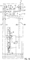
- Fig. 5 illustrates a further embodiment of an electro-hydraulic control S, with respect to the previously shown additional sections 41 and 47 are shown.
- the section 41 contains shock valves 42, which connect the working lines 12, 13 with the control lines 22, 22 'and can respond in a shock condition.
- the section 47 serves to provide an additional pressure control, similar to a secondary pressure limiting, mainly the pressure in the working lines 12, 13 in the control positions of the 4/3-way proportional directional valve W.
- the section 47 includes a 2/2-throttle valve, the between a shut-off and throttling control positions pressure and spring-dependent is adjustable, and a shuttle valve 49 which is connected to the load pressure signal circuit, and an adjustable by a proportional solenoid against adjustable spring force drain valve 50 to the return.
- the damping device D in the pilot circuit of the load-holding valves 14, 15 contains in Fig. 5 that on the basis of Fig. 1 and 2 explained 3/2-way proportional pressure control valve 27 which is held by a spring 55 in a first switching position, and when energizing a proportional solenoid 28 is adjustable in regulating positions.
- the two control lines 30a, 30b are combined via check valves 39 at a node 40 and connected to an input of the 3/2-way proportional pressure control valve 27 whose other input is connected to the return line 29.
- the 3/2-way proportional pressure control valve 27 is connected to the node 26, which is in a control line 25, 25 'connecting line 54 between two pairs of opposing check valves 46, 46'.
- the control lines 22, 22' are connected.
- the damping device D in Fig. 5 in the two control lines 22, 22 ' arranged remindström-Dämpfsysteme 43 (optional), each consisting of a blocking in the reverse flow check valve 44 and a nozzle 45 in a bypass loop of the check valve 44.
- the 3/2-way proportional pressure control valve 27 can be in accordance with the energization of the Proportional magnet 28 variably modulate the damping in the control of the load-holding valves 14, 15 or regulate.
- the Zu Kunststoffschulen the load-holding valves 14, 15 can be the same or different attenuated via the outflow-damping systems 43 (depending on Düsenbe Publishedung).
- only one outflow damping system 43 could be arranged in a control line.
- the electro-hydraulic control S in FIG Fig. 6 is the Auf interviewedung or Zu Kunststoffung the load-holding valves 14, 15 damped in that the pressure control section 47 (see Fig. 5 ) is connected in each case via a check valve of each check valve pair 46, 46 'and connecting lines from the control lines 22, 22' to the 2/2-way throttle valve 48 to the pilot control circuit K, the control lines 22, 22 'two further shuttle valves 51, 51' contain, of which lines 52, 52 'lead to the control lines 25, 25'. Between at least one shuttle valve 51, 51 'and the respective upstream side of a load-holding valve 14, 15 may optionally be a remindström-damping system 43 (not shown) as in Fig. 5 be included.
- the damping can be at least when controlling the load-holding valves 14, 15 vary.
- the control lines 30a, 30b of the pressure pilot controls of the 4/3-way proportional directional slide W are connected to the shuttle valves 24, 24 'in order to be able to control the load-holding valves 14, 15 in the zero position in a damped manner.
- the in the pilot circuit K in Fig. 7 integrated damping device D at least for controlling the load holding valves 14, 15 differs from those of the previous embodiments mainly in that a 2/2-proportional throttle valve 27 "(electro-proportional throttle) is provided between the node 26 in the control line 54 and the return line 29
- the node 26 is located between the non-return valves of the opposing check valve pair 46, which block in the flow direction to the shuttle valves 24, 24 '
- the control lines 25, 25' for controlling the load holding valves 14, 15 cross in the control positions of the 4/3-way proportional Directional slide W are also connected to the shuttle valves 24, 24 'and connected via the nozzles 37 and 38 to the return line 29.
- the embodiment of the electro-hydraulic control S in Fig. 8 is the of Fig. 5 similar.
- a variable damping of the control of the load-holding valves 14, 15 is possible not only at the transition to or from and during the floating position, but also in the control positions of the 4/3-way proportional directional valve W from whose Druckvor Kunststoffmaschine 7, 8, the control lines 30a, 30b are fed, which are combined via check valves 39 and connected to a port of the 3/2-way proportional pressure control valve 27, the second port is connected to the return line 29.
- the 3/2-way proportional pressure control valve 27 is connected to the node 26 in the control line 54, in which the two check valve pairs 46, 46 'are arranged.
- the damping can be varied via the proportional magnet 28.
- the embodiment of the electro-hydraulic control S in Fig. 9 is the of Fig. 8 similar. However, only the right load-holding valve 15 (eg used to lower the load L) is damped controlled or controlled, while the left load-holding valve 14 from the control line 25 'can be applied, or not at all.
- the nozzle assembly in the damping device D also contributes to additional or fundamental damping.
- outflow-damping systems 43 are additionally provided in the control lines 22, 22 'to the control sides of the load-holding valves 14, 15. This also allows the Zu Kunststoffière each load-holding valve 14, 15 perform steamed. If appropriate, only one outflow damping system 43 could be provided in one of the two control lines 22, 22 '.
- the damping is varied via the proportionally controlled pressures in the control lines 30a, 30b by the pressure pilot controls 7, 8 of the 4/3-way proportional directional valve W.
- the proportional magnets 9, 10 are the same but different energized to delay the timing or only partially réelle Kunststoff Kunststoff Kunststoffn and so to dampen.
- return flow damping systems 43 are included in the working lines 12, 13, each with a check valve 44 which blocks in the outflow direction, and a nozzle 45 in the line loop surrounding the check valve 44.
- control pressures derived from the control lines 30a, 30b from the pressure pilot controls of the 4/3-way proportional directional shifter W could alternatively also be used in the embodiments of FIGS Fig. 4 to 9 directly the control pressure can be tapped from the control pressure supply bypassing the pressure pilot controls.
- the damping function of the damping device D could, for example, by means of a push button or a program routine in an electronic control of the electro-hydraulic control be activated or be, and then run automatically, without an operator needs to worry about it.
- a raised attachment would automatically be lowered when adjusting the floating position to ground contact, even after a jumping motion when passing a survey, and could even in a control position, for example, with adjusted ground pressure of an attachment this slows down after a jumping motion due to a bottom elevation again to ground contact and lowered until the set ground pressure builds up.
- a significantly improved work result can thus be achieved.
Landscapes
- Engineering & Computer Science (AREA)
- Physics & Mathematics (AREA)
- Fluid Mechanics (AREA)
- Mechanical Engineering (AREA)
- General Engineering & Computer Science (AREA)
- Fluid-Pressure Circuits (AREA)
Claims (13)
- Commande électrohydraulique (S) d'au moins un récepteur hydraulique (Z) pour déplacer une charge (L) par l'intermédiaire d'une vanne à tiroir de direction multi-positions et multi-voies (W) présentant des commandes de pression pilotes (7, 8), comprenant des vannes de maintien de charge (14, 15), qui sont agencées dans des conduites de travail (12, 13) du récepteur hydraulique (Z), et peuvent être commandées hydrauliquement en ouverture au moins avec une pression de commande en provenance d'un circuit de commande pilote (K) raccordé à une alimentation de pression de commande (3), la vanne à tiroir multi-positions et multi-voies (W) présentant une position zéro dans laquelle les conduites de travail (12, 13) sont isolées d'une source de pression (1) et sont fermées, et une position flottante pouvant être réglée, dans laquelle les conduites de travail (12, 13) isolées de la source de pression (1), peuvent être reliées à un retour (2), caractérisée en ce que la vanne à tiroir de direction multi-positions et multi-voies (W) est une vanne à tiroir proportionnelle 4/3, et la position flottante peut être réglée, dans la position zéro (O) avec dans la vanne à tiroir proportionnelle 4/3 des conduites de travail (12, 13) isolées de la source de pression (1) et passantes vers le retour (2), par commande à l'ouverture des vannes de maintien de charge (14, 15), en ce que le circuit de commande pilote (K) des vannes de maintien de charge (14, 15) présente un dispositif d'amortissement (D), qui, tout au moins lors du passage vers ou hors de la position flottante et/ou dans la position flottante,
amortit la commande d'ouverture d'au moins une des vannes de maintien de charge (14, 15) avec un amortissement réglé à une valeur fixe ou variable, et en ce que la position flottante peut être réglée dans la position zéro (O) par commande à l'ouverture des vannes de maintien de charge (14, 15) par l'intermédiaire du dispositif d'amortissement (D), soit directement à partir des deux commandes de pression pilotes (7, 8) commandées simultanément et de manière proportionnelle identique et raccordées à l'alimentation de pression de commande (3), soit directement avec une pression de commande en provenance de l'alimentation de pression de commande (3). - Commande électrohydraulique selon la revendication 1, caractérisée en ce que le dispositif d'amortissement (D) dans le circuit de commande pilote (K) renferme pour un amortissement réglé de manière fixe, au moins un ajutage (23, 23', 33, 35, 45).
- Commande électrohydraulique selon la revendication 1, caractérisée en ce que l'amortissement variable par l'intermédiaire du dispositif d'amortissement (D), peut être exécuté de manière proportionnelle à partir des commandes de pression pilotes (7, 8) de la vanne à tiroir proportionnelle 4/3 au moyen des aimants proportionnels (9, 10).
- Commande électrohydraulique selon la revendication 1, caractérisée en ce que le dispositif d'amortissement (D) renferme, pour l'amortissement variable, entre l'alimentation de pression de commande (3) respectivement les commandes de pression pilotes (7, 8) et le retour (2) et les côtés de commande d'ouverture (21, 21') des vannes de maintien de charge (14, 15), une vanne 3/2 voies de régulation proportionnelle de pression (27) ou une vanne 3/2 voies de commutation tout ou rien (27'), de préférence sur le côté opposé à celui où se trouvent les vannes de maintien de charge (14, 15), de deux vannes d'inversion (24, 24') et/ou d'au moins une paire de vannes antiretour (46, 46') montées en opposition.
- Commande électrohydraulique selon la revendication 1, caractérisée en ce que le dispositif d'amortissement (D) renferme, pour l'amortissement variable, entre le retour (2, 29) et les côtés de commande d'ouverture (21, 21') des vannes de maintien de charge (14, 15) raccordés à l'alimentation de pression de commande (3) ou aux commandes de pression pilotes (7, 8), une vanne d'étranglement 2/2 voies électro-proportionnelle, de préférence sur le côté opposé à celui où se trouvent les vannes de maintien de charge (14, 15), de deux vannes d'inversion (24, 24') et/ou d'au moins une paire de vannes antiretour (46, 46').
- Commande électrohydraulique selon la revendication 1, caractérisée en ce qu'il est prévu une section de régulation proportionnelle de pression (47) raccordée aux conduites de travail (12, 13), pour les pressions de travail dans les conduites de travail (12, 13) dans des positions de commande de la vanne à tiroir proportionnelle 4/3, et en ce que le circuit de commande pilote (K), pour effectuer l'amortissement variable, est raccordé, côté aval, à la section de régulation proportionnelle de pression (47) et peut être déchargé de manière régulée vers le retour (2), par l'intermédiaire de la section de régulation proportionnelle de pression (47).
- Commande électrohydraulique selon la revendication 1, caractérisée en ce que l'amortissement réglé de manière fixe ou l'amortissement variable, est identique ou différent pour les deux vannes de maintien de charge (14, 15).
- Commande électrohydraulique selon la revendication 1, caractérisée en ce que l'amortissement réglé de manière fixe ou l'amortissement variable, par l'intermédiaire du dispositif d'amortissement (D), peut également être réglé dans au moins une position de commande (a, b) de la vanne à tiroir proportionnelle 4/3 en-dehors de la position zéro.
- Commande électrohydraulique selon la revendication 2, caractérisée en ce que dans le circuit de commande pilote (K) est agencé respectivement un ajutage (23, 23') sur le côté de commande d'ouverture (21, 21') de la vanne de maintien de charge (14, 15), les ajutages étant de dimension identique ou différente.
- Commande électrohydraulique selon la revendication 1, caractérisée en ce qu'à partir des commandes de pression pilotes (7, 8) de la vanne à tiroir proportionnelle 4/3, des conduites de commande (30a, 30b) séparées mènent respectivement à l'une des deux vannes d'inversion (24, 24') dans le circuit de commande pilote (K), et en ce que dans l'une seulement des conduites de commande (3a, 3b) est agencé un ajutage (33).
- Commande électrohydraulique selon l'une au moins des revendications précédentes, caractérisée en ce que dans les conduites de travail (12, 13) et/ou dans des conduites de commande (22, 22') vers les côtés de commande d'ouverture (21, 21') des vannes de maintien de charge (14, 15), sont agencés des systèmes d'amortissement d'écoulement de retour (43), de préférence constitués chacun d'une vanne antiretour (44) bloquant dans la direction d'évacuation et d'un ajutage (45) contournant la vanne antiretour (44).
- Commande électrohydraulique selon la revendication 1, caractérisée en ce que chaque vanne de maintien de charge (14, 15) comprend, soit une vanne d'évacuation (16), qui peut être contournée par une vanne antiretour (20) dans la direction d'alimentation, et qui, sur un côté de commande de fermeture du côté d'alimentation est commandée par pression pilote à partir de la conduite de travail (12, 13) et chargée par ressort, et sur le côté de commande d'ouverture (21, 21') en aval de la vanne antiretour (20), est commandée par pression pilote à partir de la conduite de travail (12, 13) et à partir du circuit de commande pilote (K), soit une vanne de régulation de pression 2/2 voies (16') à vanne antiretour (20') intégrée, la vanne de régulation de pression 2/2 voies (16') étant chargée par une force de ressort (17) vers une position de blocage d'écoulement de retour, et commandée par pression pilote à partir du circuit de commande pilote (K), vers des positions de passage variables.
- Régulation électronique de groupe de relevage (EHR) d'un véhicule de travail mobile comprenant au moins un outil porté pouvant être actionné par l'intermédiaire d'un récepteur hydraulique (Z) et comprenant une commande électrohydraulique (S) selon l'une au moins des revendications précédentes.
Priority Applications (1)
| Application Number | Priority Date | Filing Date | Title |
|---|---|---|---|
| EP12179874.8A EP2696080B1 (fr) | 2012-08-09 | 2012-08-09 | Electro-hydraulic control |
Applications Claiming Priority (1)
| Application Number | Priority Date | Filing Date | Title |
|---|---|---|---|
| EP12179874.8A EP2696080B1 (fr) | 2012-08-09 | 2012-08-09 | Electro-hydraulic control |
Publications (2)
| Publication Number | Publication Date |
|---|---|
| EP2696080A1 EP2696080A1 (fr) | 2014-02-12 |
| EP2696080B1 true EP2696080B1 (fr) | 2016-12-14 |
Family
ID=46634064
Family Applications (1)
| Application Number | Title | Priority Date | Filing Date |
|---|---|---|---|
| EP12179874.8A Not-in-force EP2696080B1 (fr) | 2012-08-09 | 2012-08-09 | Electro-hydraulic control |
Country Status (1)
| Country | Link |
|---|---|
| EP (1) | EP2696080B1 (fr) |
Families Citing this family (2)
| Publication number | Priority date | Publication date | Assignee | Title |
|---|---|---|---|---|
| US10820471B2 (en) | 2018-08-24 | 2020-11-03 | Cnh Industrial America Llc | Hydraulic system for an agricultural implement incorporating an implement-based override valve |
| US10820470B2 (en) | 2018-08-24 | 2020-11-03 | Cnh Industrial America Llc | Hydraulic system for an agricultural implement incorporating implement-based hydraulic load sensing |
Family Cites Families (7)
| Publication number | Priority date | Publication date | Assignee | Title |
|---|---|---|---|---|
| DE4021347A1 (de) * | 1990-07-05 | 1992-01-16 | Heilmeier & Weinlein | Hydraulische steuervorrichtung |
| DE19919014C2 (de) | 1999-04-27 | 2001-03-01 | Danfoss Fluid Power As Nordbor | Hydraulikventil mit einer Verriegelungs- und einer Schwimmfunktion |
| DE19931142C2 (de) * | 1999-07-06 | 2002-07-18 | Sauer Danfoss Holding As Nordb | Hydraulische Ventilanordnung mit Verriegelungsfunktion |
| EP1528264A1 (fr) * | 2003-10-30 | 2005-05-04 | OIL CONTROL S.p.A. | Vanne avec accumulateur pour amortir les fluctuations de la pression pilote |
| DE102004033316A1 (de) | 2004-07-09 | 2006-02-09 | Bosch Rexroth Aktiengesellschaft | Verfahren zur Ansteuerung einer Hubwerksventilanordnung |
| KR100849500B1 (ko) * | 2006-11-29 | 2008-07-31 | 볼보 컨스트럭션 이키프먼트 홀딩 스웨덴 에이비 | 플로팅 기능이 구비된 더블 체크밸브 |
| EP2466153B1 (fr) | 2010-12-17 | 2013-08-14 | HAWE Hydraulik SE | Dispositif de commande hydroélectrique |
-
2012
- 2012-08-09 EP EP12179874.8A patent/EP2696080B1/fr not_active Not-in-force
Non-Patent Citations (1)
| Title |
|---|
| None * |
Also Published As
| Publication number | Publication date |
|---|---|
| EP2696080A1 (fr) | 2014-02-12 |
Similar Documents
| Publication | Publication Date | Title |
|---|---|---|
| DE19956717B4 (de) | Hydrauliksteuergerät | |
| EP2031256B1 (fr) | Dispositif de levage et procédé de commande d'un dispositif de levage | |
| EP0499694B1 (fr) | Dispositif de commande hydraulique | |
| EP1766146B1 (fr) | Systeme de soupapes de mecanisme de levage | |
| DE10344480B3 (de) | Hydraulische Ventilanordnung | |
| EP1355065B1 (fr) | Commande hydraulique | |
| EP0760908B1 (fr) | Systeme de commande pour au moins deux consommateurs hydrauliques | |
| DE102004050294B3 (de) | Hydraulische Ventilanordnung | |
| DE19754828C2 (de) | Hydraulische Steueranordnung für eine mobile Arbeitsmaschine, insbesondere für einen Radlader, zur Dämpfung von Nickschwingungen | |
| DE19828963A1 (de) | Hydraulische Schaltung | |
| EP1450048A1 (fr) | Agencement de vanne | |
| DE102007029355A1 (de) | Hydraulische Steueranordnung | |
| EP1281872A1 (fr) | Dispositif electro-hydraulique pour le contrôle d'un moteur à double effet | |
| EP2142808B1 (fr) | Ensemble de commande hydraulique | |
| DE19831595A1 (de) | Hydraulische Schaltung | |
| EP2696080B1 (fr) | Electro-hydraulic control | |
| DE4231399A1 (de) | Hydraulische Steuereinrichtung | |
| WO2009015502A1 (fr) | Dispositif de commande pour au moins deux commandes hydrauliques | |
| EP2016818B1 (fr) | Dispositif de levage et procédé de commande d'un tel dispositif de levage | |
| DE19735482B4 (de) | Hydraulisches System mit einem Differentialzylinder und einem Eilgangventil | |
| DE102008064064A1 (de) | Hydraulische Steueranordnung | |
| DE19548943B4 (de) | Ventilanordnung | |
| EP2799722B1 (fr) | Commande hydraulique | |
| EP2157319B1 (fr) | Commande hydraulique pour un moteur hydraulique | |
| EP2597209B1 (fr) | Système de réglage d'un dispositif de levage hydro-électronique |
Legal Events
| Date | Code | Title | Description |
|---|---|---|---|
| 17P | Request for examination filed |
Effective date: 20130319 |
|
| AK | Designated contracting states |
Kind code of ref document: A1 Designated state(s): AL AT BE BG CH CY CZ DE DK EE ES FI FR GB GR HR HU IE IS IT LI LT LU LV MC MK MT NL NO PL PT RO RS SE SI SK SM TR |
|
| AX | Request for extension of the european patent |
Extension state: BA ME |
|
| PUAI | Public reference made under article 153(3) epc to a published international application that has entered the european phase |
Free format text: ORIGINAL CODE: 0009012 |
|
| GRAP | Despatch of communication of intention to grant a patent |
Free format text: ORIGINAL CODE: EPIDOSNIGR1 |
|
| INTG | Intention to grant announced |
Effective date: 20160706 |
|
| GRAS | Grant fee paid |
Free format text: ORIGINAL CODE: EPIDOSNIGR3 |
|
| GRAA | (expected) grant |
Free format text: ORIGINAL CODE: 0009210 |
|
| AK | Designated contracting states |
Kind code of ref document: B1 Designated state(s): AL AT BE BG CH CY CZ DE DK EE ES FI FR GB GR HR HU IE IS IT LI LT LU LV MC MK MT NL NO PL PT RO RS SE SI SK SM TR |
|
| REG | Reference to a national code |
Ref country code: GB Ref legal event code: FG4D Free format text: NOT ENGLISH |
|
| REG | Reference to a national code |
Ref country code: CH Ref legal event code: EP |
|
| REG | Reference to a national code |
Ref country code: IE Ref legal event code: FG4D Free format text: LANGUAGE OF EP DOCUMENT: GERMAN |
|
| REG | Reference to a national code |
Ref country code: AT Ref legal event code: REF Ref document number: 853863 Country of ref document: AT Kind code of ref document: T Effective date: 20170115 |
|
| REG | Reference to a national code |
Ref country code: DE Ref legal event code: R096 Ref document number: 502012009010 Country of ref document: DE |
|
| PG25 | Lapsed in a contracting state [announced via postgrant information from national office to epo] |
Ref country code: LV Free format text: LAPSE BECAUSE OF FAILURE TO SUBMIT A TRANSLATION OF THE DESCRIPTION OR TO PAY THE FEE WITHIN THE PRESCRIBED TIME-LIMIT Effective date: 20161214 |
|
| REG | Reference to a national code |
Ref country code: LT Ref legal event code: MG4D |
|
| REG | Reference to a national code |
Ref country code: NL Ref legal event code: MP Effective date: 20161214 |
|
| PG25 | Lapsed in a contracting state [announced via postgrant information from national office to epo] |
Ref country code: LT Free format text: LAPSE BECAUSE OF FAILURE TO SUBMIT A TRANSLATION OF THE DESCRIPTION OR TO PAY THE FEE WITHIN THE PRESCRIBED TIME-LIMIT Effective date: 20161214 Ref country code: GR Free format text: LAPSE BECAUSE OF FAILURE TO SUBMIT A TRANSLATION OF THE DESCRIPTION OR TO PAY THE FEE WITHIN THE PRESCRIBED TIME-LIMIT Effective date: 20170315 Ref country code: SE Free format text: LAPSE BECAUSE OF FAILURE TO SUBMIT A TRANSLATION OF THE DESCRIPTION OR TO PAY THE FEE WITHIN THE PRESCRIBED TIME-LIMIT Effective date: 20161214 Ref country code: NO Free format text: LAPSE BECAUSE OF FAILURE TO SUBMIT A TRANSLATION OF THE DESCRIPTION OR TO PAY THE FEE WITHIN THE PRESCRIBED TIME-LIMIT Effective date: 20170314 |
|
| PG25 | Lapsed in a contracting state [announced via postgrant information from national office to epo] |
Ref country code: FI Free format text: LAPSE BECAUSE OF FAILURE TO SUBMIT A TRANSLATION OF THE DESCRIPTION OR TO PAY THE FEE WITHIN THE PRESCRIBED TIME-LIMIT Effective date: 20161214 Ref country code: HR Free format text: LAPSE BECAUSE OF FAILURE TO SUBMIT A TRANSLATION OF THE DESCRIPTION OR TO PAY THE FEE WITHIN THE PRESCRIBED TIME-LIMIT Effective date: 20161214 Ref country code: RS Free format text: LAPSE BECAUSE OF FAILURE TO SUBMIT A TRANSLATION OF THE DESCRIPTION OR TO PAY THE FEE WITHIN THE PRESCRIBED TIME-LIMIT Effective date: 20161214 |
|
| PG25 | Lapsed in a contracting state [announced via postgrant information from national office to epo] |
Ref country code: NL Free format text: LAPSE BECAUSE OF FAILURE TO SUBMIT A TRANSLATION OF THE DESCRIPTION OR TO PAY THE FEE WITHIN THE PRESCRIBED TIME-LIMIT Effective date: 20161214 |
|
| PG25 | Lapsed in a contracting state [announced via postgrant information from national office to epo] |
Ref country code: IS Free format text: LAPSE BECAUSE OF FAILURE TO SUBMIT A TRANSLATION OF THE DESCRIPTION OR TO PAY THE FEE WITHIN THE PRESCRIBED TIME-LIMIT Effective date: 20170414 Ref country code: SK Free format text: LAPSE BECAUSE OF FAILURE TO SUBMIT A TRANSLATION OF THE DESCRIPTION OR TO PAY THE FEE WITHIN THE PRESCRIBED TIME-LIMIT Effective date: 20161214 Ref country code: RO Free format text: LAPSE BECAUSE OF FAILURE TO SUBMIT A TRANSLATION OF THE DESCRIPTION OR TO PAY THE FEE WITHIN THE PRESCRIBED TIME-LIMIT Effective date: 20161214 Ref country code: CZ Free format text: LAPSE BECAUSE OF FAILURE TO SUBMIT A TRANSLATION OF THE DESCRIPTION OR TO PAY THE FEE WITHIN THE PRESCRIBED TIME-LIMIT Effective date: 20161214 Ref country code: EE Free format text: LAPSE BECAUSE OF FAILURE TO SUBMIT A TRANSLATION OF THE DESCRIPTION OR TO PAY THE FEE WITHIN THE PRESCRIBED TIME-LIMIT Effective date: 20161214 |
|
| PG25 | Lapsed in a contracting state [announced via postgrant information from national office to epo] |
Ref country code: SM Free format text: LAPSE BECAUSE OF FAILURE TO SUBMIT A TRANSLATION OF THE DESCRIPTION OR TO PAY THE FEE WITHIN THE PRESCRIBED TIME-LIMIT Effective date: 20161214 Ref country code: ES Free format text: LAPSE BECAUSE OF FAILURE TO SUBMIT A TRANSLATION OF THE DESCRIPTION OR TO PAY THE FEE WITHIN THE PRESCRIBED TIME-LIMIT Effective date: 20161214 Ref country code: PL Free format text: LAPSE BECAUSE OF FAILURE TO SUBMIT A TRANSLATION OF THE DESCRIPTION OR TO PAY THE FEE WITHIN THE PRESCRIBED TIME-LIMIT Effective date: 20161214 Ref country code: PT Free format text: LAPSE BECAUSE OF FAILURE TO SUBMIT A TRANSLATION OF THE DESCRIPTION OR TO PAY THE FEE WITHIN THE PRESCRIBED TIME-LIMIT Effective date: 20170414 Ref country code: IT Free format text: LAPSE BECAUSE OF FAILURE TO SUBMIT A TRANSLATION OF THE DESCRIPTION OR TO PAY THE FEE WITHIN THE PRESCRIBED TIME-LIMIT Effective date: 20161214 Ref country code: BG Free format text: LAPSE BECAUSE OF FAILURE TO SUBMIT A TRANSLATION OF THE DESCRIPTION OR TO PAY THE FEE WITHIN THE PRESCRIBED TIME-LIMIT Effective date: 20170314 |
|
| REG | Reference to a national code |
Ref country code: DE Ref legal event code: R097 Ref document number: 502012009010 Country of ref document: DE |
|
| PLBE | No opposition filed within time limit |
Free format text: ORIGINAL CODE: 0009261 |
|
| STAA | Information on the status of an ep patent application or granted ep patent |
Free format text: STATUS: NO OPPOSITION FILED WITHIN TIME LIMIT |
|
| 26N | No opposition filed |
Effective date: 20170915 |
|
| PG25 | Lapsed in a contracting state [announced via postgrant information from national office to epo] |
Ref country code: DK Free format text: LAPSE BECAUSE OF FAILURE TO SUBMIT A TRANSLATION OF THE DESCRIPTION OR TO PAY THE FEE WITHIN THE PRESCRIBED TIME-LIMIT Effective date: 20161214 |
|
| PG25 | Lapsed in a contracting state [announced via postgrant information from national office to epo] |
Ref country code: SI Free format text: LAPSE BECAUSE OF FAILURE TO SUBMIT A TRANSLATION OF THE DESCRIPTION OR TO PAY THE FEE WITHIN THE PRESCRIBED TIME-LIMIT Effective date: 20161214 |
|
| REG | Reference to a national code |
Ref country code: CH Ref legal event code: PL |
|
| PG25 | Lapsed in a contracting state [announced via postgrant information from national office to epo] |
Ref country code: MC Free format text: LAPSE BECAUSE OF FAILURE TO SUBMIT A TRANSLATION OF THE DESCRIPTION OR TO PAY THE FEE WITHIN THE PRESCRIBED TIME-LIMIT Effective date: 20161214 |
|
| GBPC | Gb: european patent ceased through non-payment of renewal fee |
Effective date: 20170809 |
|
| PG25 | Lapsed in a contracting state [announced via postgrant information from national office to epo] |
Ref country code: LI Free format text: LAPSE BECAUSE OF NON-PAYMENT OF DUE FEES Effective date: 20170831 Ref country code: CH Free format text: LAPSE BECAUSE OF NON-PAYMENT OF DUE FEES Effective date: 20170831 |
|
| REG | Reference to a national code |
Ref country code: DE Ref legal event code: R082 Ref document number: 502012009010 Country of ref document: DE Representative=s name: GROSSE, SCHUMACHER, KNAUER, VON HIRSCHHAUSEN, DE Ref country code: DE Ref legal event code: R081 Ref document number: 502012009010 Country of ref document: DE Owner name: HAWE HYDRAULIK SE, DE Free format text: FORMER OWNER: HAWE HYDRAULIK SE, 81673 MUENCHEN, DE |
|
| REG | Reference to a national code |
Ref country code: FR Ref legal event code: ST Effective date: 20180430 |
|
| REG | Reference to a national code |
Ref country code: IE Ref legal event code: MM4A |
|
| REG | Reference to a national code |
Ref country code: BE Ref legal event code: MM Effective date: 20170831 |
|
| PG25 | Lapsed in a contracting state [announced via postgrant information from national office to epo] |
Ref country code: LU Free format text: LAPSE BECAUSE OF NON-PAYMENT OF DUE FEES Effective date: 20170809 |
|
| PG25 | Lapsed in a contracting state [announced via postgrant information from national office to epo] |
Ref country code: GB Free format text: LAPSE BECAUSE OF NON-PAYMENT OF DUE FEES Effective date: 20170809 Ref country code: IE Free format text: LAPSE BECAUSE OF NON-PAYMENT OF DUE FEES Effective date: 20170809 |
|
| PG25 | Lapsed in a contracting state [announced via postgrant information from national office to epo] |
Ref country code: BE Free format text: LAPSE BECAUSE OF NON-PAYMENT OF DUE FEES Effective date: 20170831 Ref country code: FR Free format text: LAPSE BECAUSE OF NON-PAYMENT OF DUE FEES Effective date: 20170831 |
|
| PG25 | Lapsed in a contracting state [announced via postgrant information from national office to epo] |
Ref country code: MT Free format text: LAPSE BECAUSE OF FAILURE TO SUBMIT A TRANSLATION OF THE DESCRIPTION OR TO PAY THE FEE WITHIN THE PRESCRIBED TIME-LIMIT Effective date: 20161214 |
|
| REG | Reference to a national code |
Ref country code: AT Ref legal event code: MM01 Ref document number: 853863 Country of ref document: AT Kind code of ref document: T Effective date: 20170809 |
|
| PG25 | Lapsed in a contracting state [announced via postgrant information from national office to epo] |
Ref country code: AT Free format text: LAPSE BECAUSE OF NON-PAYMENT OF DUE FEES Effective date: 20170809 |
|
| PG25 | Lapsed in a contracting state [announced via postgrant information from national office to epo] |
Ref country code: HU Free format text: LAPSE BECAUSE OF FAILURE TO SUBMIT A TRANSLATION OF THE DESCRIPTION OR TO PAY THE FEE WITHIN THE PRESCRIBED TIME-LIMIT; INVALID AB INITIO Effective date: 20120809 |
|
| PG25 | Lapsed in a contracting state [announced via postgrant information from national office to epo] |
Ref country code: CY Free format text: LAPSE BECAUSE OF NON-PAYMENT OF DUE FEES Effective date: 20161214 |
|
| PGFP | Annual fee paid to national office [announced via postgrant information from national office to epo] |
Ref country code: DE Payment date: 20190828 Year of fee payment: 8 |
|
| PG25 | Lapsed in a contracting state [announced via postgrant information from national office to epo] |
Ref country code: MK Free format text: LAPSE BECAUSE OF FAILURE TO SUBMIT A TRANSLATION OF THE DESCRIPTION OR TO PAY THE FEE WITHIN THE PRESCRIBED TIME-LIMIT Effective date: 20161214 |
|
| PG25 | Lapsed in a contracting state [announced via postgrant information from national office to epo] |
Ref country code: TR Free format text: LAPSE BECAUSE OF FAILURE TO SUBMIT A TRANSLATION OF THE DESCRIPTION OR TO PAY THE FEE WITHIN THE PRESCRIBED TIME-LIMIT Effective date: 20161214 |
|
| PG25 | Lapsed in a contracting state [announced via postgrant information from national office to epo] |
Ref country code: AL Free format text: LAPSE BECAUSE OF FAILURE TO SUBMIT A TRANSLATION OF THE DESCRIPTION OR TO PAY THE FEE WITHIN THE PRESCRIBED TIME-LIMIT Effective date: 20161214 |
|
| REG | Reference to a national code |
Ref country code: DE Ref legal event code: R119 Ref document number: 502012009010 Country of ref document: DE |
|
| PG25 | Lapsed in a contracting state [announced via postgrant information from national office to epo] |
Ref country code: DE Free format text: LAPSE BECAUSE OF NON-PAYMENT OF DUE FEES Effective date: 20210302 |