EP2693407B1 - Verfahren und Vorrichtung zur Optimierung des RFID-Feldes einer Zugangskontrolleinrichtung - Google Patents
Verfahren und Vorrichtung zur Optimierung des RFID-Feldes einer Zugangskontrolleinrichtung Download PDFInfo
- Publication number
- EP2693407B1 EP2693407B1 EP13003807.8A EP13003807A EP2693407B1 EP 2693407 B1 EP2693407 B1 EP 2693407B1 EP 13003807 A EP13003807 A EP 13003807A EP 2693407 B1 EP2693407 B1 EP 2693407B1
- Authority
- EP
- European Patent Office
- Prior art keywords
- rfid
- lock
- tuning
- transmitting
- reader
- Prior art date
- Legal status (The legal status is an assumption and is not a legal conclusion. Google has not performed a legal analysis and makes no representation as to the accuracy of the status listed.)
- Active
Links
Images

Classifications
-
- G—PHYSICS
- G06—COMPUTING OR CALCULATING; COUNTING
- G06K—GRAPHICAL DATA READING; PRESENTATION OF DATA; RECORD CARRIERS; HANDLING RECORD CARRIERS
- G06K7/00—Methods or arrangements for sensing record carriers, e.g. for reading patterns
- G06K7/10—Methods or arrangements for sensing record carriers, e.g. for reading patterns by electromagnetic radiation, e.g. optical sensing; by corpuscular radiation
- G06K7/10009—Methods or arrangements for sensing record carriers, e.g. for reading patterns by electromagnetic radiation, e.g. optical sensing; by corpuscular radiation sensing by radiation using wavelengths larger than 0.1 mm, e.g. radio-waves or microwaves
- G06K7/10158—Methods or arrangements for sensing record carriers, e.g. for reading patterns by electromagnetic radiation, e.g. optical sensing; by corpuscular radiation sensing by radiation using wavelengths larger than 0.1 mm, e.g. radio-waves or microwaves methods and means used by the interrogation device for reliably powering the wireless record carriers using an electromagnetic interrogation field
- G06K7/10178—Methods or arrangements for sensing record carriers, e.g. for reading patterns by electromagnetic radiation, e.g. optical sensing; by corpuscular radiation sensing by radiation using wavelengths larger than 0.1 mm, e.g. radio-waves or microwaves methods and means used by the interrogation device for reliably powering the wireless record carriers using an electromagnetic interrogation field including auxiliary means for focusing, repeating or boosting the electromagnetic interrogation field
-
- G—PHYSICS
- G07—CHECKING-DEVICES
- G07C—TIME OR ATTENDANCE REGISTERS; REGISTERING OR INDICATING THE WORKING OF MACHINES; GENERATING RANDOM NUMBERS; VOTING OR LOTTERY APPARATUS; ARRANGEMENTS, SYSTEMS OR APPARATUS FOR CHECKING NOT PROVIDED FOR ELSEWHERE
- G07C9/00—Individual registration on entry or exit
- G07C9/00174—Electronically operated locks; Circuits therefor; Nonmechanical keys therefor, e.g. passive or active electrical keys or other data carriers without mechanical keys
- G07C9/00944—Details of construction or manufacture
Definitions
- the invention relates to a method and a device for optimizing the RFID field of an access control device according to the preamble of claim 1.
- Such access control device is installed, for example, in a lock a central locking system, but this is only to be understood as an embodiment of the invention.
- the invention relates to all access control devices that operate according to the RFID principle, in the following - for ease of description because - only a preferred embodiment is given, which refers to the fact that an RFID field is optimized in a lock a central locking system.
- the identification information is transmitted in systems that are standardized in accordance with ISO 18000-1 ff. As follows: The reader (reader), which can also write data depending on the type, generates a high-frequency electromagnetic alternating field which is integrated in the lock Transmitting and receiving antenna captured in front of the lock RFID transponder (RFID tag) detected. The radio frequency energy absorbed by him via the antenna simultaneously serves as a power supply for his chip during the communication process.
- the thus activated microchip in the RFID tag decodes the commands sent by the reader.
- the response is encoded and modulated by the RFID tag in the radiated electromagnetic field by field weakening in non-contact short circuit or by out-of-phase reflection of the field emitted by the reader.
- the day transmits its own unchanging Serial number, other data of the designated object or other information requested by the reader.
- HF tags use load modulation, that is, they use short-circuiting to consume some of the energy of the alternating magnetic field. This can detect the reader, but theoretically also a distant receiver.
- the antennas of an RF tag form an induction coil with several turns.
- Another disadvantage of a manually set resonance branch in the RFID branch of the lock is, moreover, that at certain aging of the components a certain drift of the transmission channel is to be feared and after a certain time a renewed manual vote is necessary.
- EP 1 914 663 A1 discloses a method for optimizing an RFID field, wherein an existing in an RFID reader transmitting and receiving circuit, which is designed for two different frequency channels, is controlled by a microprocessor so that the detected by the RFID reader magnetic field or the radiated transmission power is optimized by the change of capacity.
- this method is not for operating an access control device.
- the invention is therefore based on the object of developing a method and a device for optimizing the RFID field in an access control device of a general type such that manual tuning of the RFID field can be dispensed with.
- the invention is characterized by the technical teaching of claim 1.
- An essential feature of the invention is that a self-learning vote of the lock-side RFID field takes place.
- the built-in lock tuning device is thus automatically controlled in response to the received field strength of the RFID field.
- the received field strength is detected and a resonant circuit in the tuner is tuned until the radiated transmission power has achieved an optimum.
- the invention is characterized in that the self-learning tuning device in the castle an RFID branch, which is wired to a lock control unit in communication.
- an automatically adjustable capacitance is arranged in the lock-side RFID branch, which changes the resonance frequency of the resonant circuit.
- the automatically adjustable capacity is controlled by a built-in lock housing microcontroller that detects the received RFID signal of the reader, evaluates and according to the received signal via the microcontroller, the variable capacitance in the RFID branch so controls that the resonant circuit always in the optimum resonant frequency held to optimize the radiated field strength.
- the invention is not limited to that the microcontroller drives a variable capacitance for changing the resonant frequency of the RFID branch.
- a variable capacitance instead of a variable capacitance, a variable inductance can also be used to change the resonant circuit of the RFID circuit.
- the invention assumes that the RFID field is received by the receiving antenna of the lock in a certain minimum strength, so that a certain reception amplitude is present at the entrance of the receiving antenna in the lock, which is then detected by the measuring branch according to the invention. This amplitude is used as an output for the control of the variable C-link.
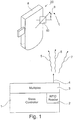
- Each channel 5, 6, 7 is assigned a separate lock 8, wherein it is assumed in the exemplary embodiment that the channel 5 to the in FIG. 1 shown lock 8 is tuned. It is important that in the lock an automatic tuning device 20 is arranged, which essentially consists of a transmitting and receiving antenna 9, the FIG. 2 is connected to a tuner 20.
- the upper branch of the tuner 20 consists of the transmitting and receiving branch 13, which contains in its essential part a tuning member 10, which is formed in the preferred embodiment as a variable capacitance. It has already been pointed out in the general part of the description that a variable inductance can also be used instead of a variable capacitance.
- variable capacitance is associated with a resonant circuit 11, which in the preferred embodiment consists of an inductor and a capacitor.
- the antenna input signal of the antenna 9 is branched off from a measuring branch 12 and rectified by RC rectifiers 15 and voltage divider 14 and fed to a microcontroller 16.
- the microcontroller detects the amplitude of the RFID signal received by the antenna 9 and supplies it to the microcontroller 16, in which inter alia an AD converter 17 is installed.
- the transmission and reception signal is constantly optimized automatically, assuming that the antenna 9 on the channel 5 via Receives a signal with the same power over a certain period of time.
- Such an automatic tuning of the RFID field is preferably carried out in the learning phase of the locks, which are associated with their digital identifiers a particular cabinet.
- a specific command sent from the host to the slave controller initiates and executes the auto-tuning phase.
- Lock control unit 11 resonant circuit 2
- RFID Reader 12 measuring branch 3 multiplexer 13
- Send and receive branch 4 14 voltage divider 5 channel 15 rectifier 6 channel 16 microcontroller 7 channel 17 ADC 8th lock 18 stub 9 Castle connection cable 19 10 tuning member 20 tuner
Landscapes
- Physics & Mathematics (AREA)
- Engineering & Computer Science (AREA)
- Electromagnetism (AREA)
- General Physics & Mathematics (AREA)
- Health & Medical Sciences (AREA)
- Toxicology (AREA)
- Computer Networks & Wireless Communication (AREA)
- Artificial Intelligence (AREA)
- Computer Vision & Pattern Recognition (AREA)
- General Health & Medical Sciences (AREA)
- Theoretical Computer Science (AREA)
- Manufacturing & Machinery (AREA)
- Near-Field Transmission Systems (AREA)
- Input Circuits Of Receivers And Coupling Of Receivers And Audio Equipment (AREA)
Description
- Die Erfindung betrifft ein Verfahren und eine Vorrichtung zur Optimierung des RFID-Feldes einer Zugangskontrolleinrichtung nach dem Oberbegriff des Patentanspruches 1.
- Eine solche Zugangskontrolleinrichtung ist beispielsweise in einem Schloss einer zentralen Schließanlage eingebaut, was jedoch nur als Ausführungsbeispiel der Erfindung zu verstehen ist. Die Erfindung betrifft also sämtliche Zugangskontrolleinrichtungen, die nach dem RFID-Prinzip arbeiten, wobei im Folgenden - der einfacheren Beschreibung wegen - nur ein bevorzugtes Ausführungsbeispiel angegeben wird, welches sich darauf bezieht, dass ein RFID-Feld in einem Schloss einer zentralen Schließanlage optimiert wird.
- Die Übertragung der Identinformation erfolgt bei Systemen, die nach ISO 18000-1 ff. genormt sind, folgendermaßen: Das Lesegerät (Reader), das je nach Typ ggf. auch Daten schreiben kann, erzeugt ein hochfrequentes elektromagnetisches Wechselfeld, welches über die im Schloss eingebaute Sende- und Empfangsantenne den vor dem Schloss platzierten RFID-Transponder (RFID-Tag) erfasst. Die von ihm über die Antenne aufgenommene Hochfrequenzenergie dient während des Kommunikationsvorganges gleichzeitig als Stromversorgung für seinen Chip.
- Der so aktivierte Mikrochip im RFID-Tag dekodiert die vom Lesegerät gesendeten Befehle. Die Antwort kodiert und moduliert der RFID-Tag in das eingestrahlte elektromagnetische Feld durch Feldschwächung im kontaktfreien Kurzschluss oder durch gegenphasige Reflexion des vom Lesegerät ausgesendeten Feldes. Damit überträgt der Tag seine eigene unveränderliche Seriennummer, weitere Daten des gekennzeichneten Objekts oder andere vom Lesegerät abgefragte Information.
HF-Tags verwenden Lastmodulation, das heißt, sie verbrauchen durch Kurzschließen einen Teil der Energie des magnetischen Wechselfeldes. Dies kann das Lesegerät, theoretisch aber auch ein weiter entfernter Empfänger, detektieren. Die Antennen eines HF-Tags bilden eine Induktionsspule mit mehreren Windungen. - Stand der Technik ist z. B. ein in einem Schrank eingebautes Schloss, welches über die Antenne ein RFID-Feld erzeugt und abstrahlt. Nachdem ein solches Schloss in metallischen Schränken oder in anderen, möglicherweise metallisch leitfähigen Umgebungen eingebaut sein kann, besteht das Problem, dass das RFID-Feld bedingt durch die metallisch leitfähige Einbausituation stark abgeschwächt oder verfälscht wird. Bisher ist es lediglich bekannt, das RFID-Feld dieses Schlosses dadurch zu optimieren, dass eine manuell veränderbare, abstimmbare Kapazität im Schloss eingebaut ist, um die Resonanzfrequenz des RFID-Feldes zu optimieren, um eine optimale Aussendung des RFID-Signals zu ermöglichen.
- Nachteil der bekannten Anordnung ist jedoch, dass ein sehr hoher manueller Aufwand beim Abgleich eines solchen RFID-gesteuerten Schlosses gegeben ist. Der Schrank muss geöffnet sein, um bei geöffneter Schranktür Zugang zu dem im Schrank eingebauten Schloss zu erhalten, damit ein manueller Abgleich der Abstimm-Kapazität erfolgen kann.
- Wird jedoch die Schranktür nach dem Abgleich wieder geschlossen, besteht die Gefahr, dass der eingestellte Abgleich dadurch verändert wird, was zu unzureichenden Ergebnissen führt.
- Weiterer Nachteil eines manuell eingestellten Resonanzzweiges im RFID-Zweig des Schlosses ist im Übrigen, dass bei bestimmter Alterung der Bauelemente eine bestimmte Drift des Sendekanals zu befürchten ist und nach einer bestimmten Zeit eine erneute manuelle Abstimmung notwendig ist.
- Die Druckschrift
EP 1 914 663 A1 offenbart ein Verfahren zur Optimierung eines RFID-Feldes, wobei ein in einem RFID-Leser vorhandener Sende- und Empfangskreis, der für zwei unterschiedliche Frequenzkanäle ausgelegt ist, von einem Mikroprozessor so angesteuert wird, dass das vom RFID-Leser detektierte magnetische Feld bzw. die abgestrahlte Sendeleistung durch die Veränderung von Kapazitäten optimiert wird.
Dieses Verfahren dient jedoch nicht zum Betreiben einer Zugangskontrollvorrichtung. - Der Erfindung liegt deshalb die Aufgabe zugrunde, ein Verfahren und eine Vorrichtung zur Optimierung des RFID-Feldes in einer Zugangskontrolleinrichtung allgemeiner Art so weiterzubilden, dass eine manuelle Abstimmung des RFID-Feldes entfallen kann.
- Zur Lösung der gestellten Aufgabe ist die Erfindung durch die technische Lehre des Anspruches 1 gekennzeichnet.
- Wesentliches Merkmal der Erfindung ist, dass eine selbstlernende Abstimmung des schlossseitigen RFID-Feldes stattfindet.
- Erfindungsgemäß wird demnach die im Schloss eingebaute Abstimmeinrichtung automatisch in Abhängigkeit von der empfangenen Feldstärke des RFID-Feldes geregelt. Es wird die empfangene Feldstärke erfasst und ein Resonanzkreis in der Abstimmeinrichtung solange abgestimmt, bis die abgestrahlte Sendeleistung ein Optimum erzielt hat.
- In einer bevorzugten Ausgestaltung der Erfindung ist die Erfindung dadurch gekennzeichnet, dass die selbstlernende Abstimmeinrichtung im Schloss aus einem RFID-Zweig besteht, der kabelgebunden mit einer Schloss- Steuereinheit in Verbindung steht.
- Bevorzugt ist im schlossseitigen RFID-Zweig eine automatisch abgleichbare Kapazität angeordnet, welche die Resonanzfrequenz des Schwingkreises verändert. Die automatisch abgleichbare Kapazität wird von einem im Schlossgehäuse eingebauten Mikrocontroller angesteuert, der das empfangene RFID-Signal des Readers erfasst, auswertet und entsprechend dem empfangenen Signal über den Mikrocontroller die veränderbare Kapazität im RFID-Zweig so ansteuert, dass der Schwingkreis stets in der optimalen Resonanzfrequenz gehalten wird, um die abgestrahlte Feldstärke zu optimieren.
- Damit erfolgt eine automatische Abstimmung des RFID-Zweiges und dessen Resonanzfrequenz, die unabhängig davon ist, ob die Schranktür geöffnet oder geschlossen ist, und die von metallischen Umgebungen oder von Veränderungen der Frequenz in Abhängigkeit von der Schlossumgebung unabhängig ist.
- Die Erfindung ist nicht darauf beschränkt, dass der Mikrocontroller eine variable Kapazität zur Veränderung der Resonanzfrequenz des RFID-Zweiges ansteuert. Statt einer variablen Kapazität kann auch eine variable Induktivität zur Veränderung des Resonanzkreises des RFID-Kreises verwendet werden.
- Die Erfindung setzt im Übrigen voraus, dass das RFID-Feld in einer bestimmten minimalen Stärke von der Empfangsantenne des Schlosses empfangen wird, sodass eine bestimmte Empfangsamplitude am Eingang der Empfangsantenne im Schloss vorliegt, die dann von dem erfindungsgemäßen Messzweig erfasst wird. Diese Amplitude wird als Ausgangsgröße für die Regelung des veränderbaren C-Gliedes verwendet.
- Der Erfindungsgegenstand der vorliegenden Erfindung ergibt sich nicht nur aus dem Gegenstand der einzelnen Patentansprüche, sondern auch aus der Kombination der einzelnen Patentansprüche untereinander.
- Im Folgenden wird die Erfindung anhand von lediglich einen Ausführungsweg darstellenden Zeichnungen näher erläutert. Hierbei gehen aus den Zeichnungen und ihrer Beschreibung weitere erfindungswesentliche Merkmale und Vorteile der Erfindung hervor.
Es zeigen: - Figur 1:
- schematisiert ein Blockschaltbild einer Anordnung einer zentralen Schließanlage
- Figur 2:
- die automatische Abstimmeinrichtung nach der Erfindung
- Jedem Kanal 5, 6, 7 ist ein eigenes Schloss 8 zugeordnet, wobei im Ausführungsbeispiel davon ausgegangen wird, dass der Kanal 5 auf das in
Figur 1 dargestellte Schloss 8 abgestimmt ist.
Wichtig ist, dass im Schloss eine automatische Abstimmeinrichtung 20 angeordnet ist, die im Wesentlichen aus einer Sende- und Empfangsantenne 9 besteht, die inFigur 2 mit einer Abstimmeinrichtung 20 verbunden ist. - Der obere Zweig der Abstimmeinrichtung 20 besteht aus dem Sende- und Empfangszweig 13, der in seinem wesentlichen Teil ein Abstimmglied 10 enthält, das im bevorzugten Ausführungsbeispiel als variable Kapazität ausgebildet ist. Es wurde bereits schon im allgemeinen Beschreibungsteil darauf hingewiesen, dass statt einer variablen Kapazität auch eine variable Induktivität verwendet werden kann.
- Die variable Kapazität ist einem Resonanzkreis 11 zugeordnet, der im bevorzugten Ausführungsbeispiel aus einer Induktivität und einer Kapazität besteht.
- Das Antenneneingangssignal der Antenne 9 wird von einem Messzweig 12 abgezweigt und über RC-Glieder und Spannungsteiler 14 von einem Gleichrichter 15 gleichgerichtet und einem Mikrocontroller 16 zugeführt.
- Der Mikrocontroller erfasst die Amplitude des von der Antenne 9 empfangenen RFID-Signals und führt dieses dem Mikrocontroller 16 zu, in dem unter anderem ein AD-Wandler 17 eingebaut ist.
- Es handelt sich um eine automatische Regelungseinrichtung, die dafür sorgt, dass der AD-Wandler über einen digitalen Abstimmzweig 18 das digitale Abstimmglied 10 ansteuert.
- Es handelt sich demnach um eine automatisch arbeitende Regelungseinrichtung, sodass über den Rückkopplungszweig (Messzweig 12) stets dafür gesorgt wird, dass das digitale Abstimmglied 10 auf einen solchen Wert eingeregelt wird, dass der Resonanzkreis 11 auf eine optimalen Resonanzfrequenz eingestellt ist.
- Auf diese Weise wird das Sende- und Empfangssignal ständig automatisch optimiert, wobei vorausgesetzt wird, dass die Antenne 9 auf dem Kanal 5 über einen gewissen Zeitraum ein mit gleicher Leistung gleichbleibendes Signal empfängt.
- Es ist vorgesehen, dass stets immer nur ein Schloss auf den automatischen Abstimmprozess eingestellt wird.
- Eine solche automatische Abstimmung des RFID-Feldes erfolgt bevorzugt in der Einlernphase der Schlösser, die mit ihren digitalen Kennungen einem bestimmten Schrank zugeordnet werden. Durch einen bestimmten Befehl, der vom Host an den Slave-Controller geleitet wird, wird die automatische Abstimmphase eingeleitet und durchgeführt.
Zeichnungslegende 1 Schloss-Steuereinheit 11 Resonanzkreis 2 RFID-Reader 12 Messzweig 3 Multiplexer 13 Sende- und Empfangszweig 4 14 Spannungsteiler 5 Kanal 15 Gleichrichter 6 Kanal 16 Mikrocontroller 7 Kanal 17 AD-Wandler 8 Schloss 18 Abstimmzweig 9 Schlossverbindungskabel 19 10 Abstimmglied 20 Abstimmeinrichtung
Claims (8)
- Verfahren zur Optimierung des RFID-Feldes einer Zugangskontrolleinrichtung, bei der ein von einem RFID-Reader (2) ausgehendes, sich über mehrere Kanäle erstreckendes RFID-Feld erzeugt wird, das den in Schränken eingebauten Schlössern (8) einer zentralen Schließanlage über eine Sende- und Empfangsantenne (9) zugeleitet wird, wobei im Schloss (8) eine mit der Sende- und Empfangsantenne (9) verbundene automatisch geregelte Abstimmeinrichtung (20) angeordnet ist, welche einen automatisch abstimmbaren Sende- und Empfangszweig (13) zur Optimierung eines Resonanzschwingkreises (11) beinhaltet, der die abgestrahlte Sendeleistung optimiert, wobei der Sende- und Empfangszweig (13) kabelgebunden mit dem Reader (2) in der Schloss- Steuereinheit in Verbindung steht, wobei die Abstimmeinrichtung (20) von einem im Schlossgehäuse eingebauten Mikrocontroller (16) angesteuert wird, der das empfangene RFID-Signal des Readers (2) erfasst, auswertet und entsprechend der Amplitude des empfangenen Signals über den Mikrocontroller (16) die Abstimmeinrichtung (20), im RFID-Zweig so ansteuert, dass der Resonanzschwingkreis (11) in der optimalen Resonanzfrequenz gehalten wird.
- Verfahren nach Anspruch 1, dadurch gekennzeichnet, dass das vom Reader (2) ausgesendete RFID-Signal im Schloss (8) erfasst und über eine veränderbare Kapazität die Resonanzfrequenz des Resonanzkreises (11) solange abgestimmt wird, bis eine optimale Resonanzfrequenz erreicht ist, um eine optimale Anpassung an die Antenne (9) im Schloss (8) zu erreichen.
- Verfahren nach Anspruch 1 oder 2, dadurch gekennzeichnet, dass die automatische Abstimmung des schlossseitigen Resonanzkreises (11) in der Einlernphase der Schlösser durch einen digitalen Befehl erfolgt, mit dem die automatische Abstimmphase eingeleitet und durchgeführt wird.
- Vorrichtung zur Optimierung des RFID-Feldes einer Zugangskontrolleinrichtung, bei der ein von einem RFID-Reader (2) ausgehendes, sich über mehrere Kanäle erstreckendes RFID-Feld erzeugt wird, das den in Schränken eingebauten Schlössern (8) einer zentralen Schließanlage über eine Sende- und Empfangsantenne (9) zugeleitet wird, wobei im Schloss (8) eine mit der Sende- und Empfangsantenne (9) verbundene automatisch geregelte Abstimmeinrichtung (20) angeordnet ist, welche einen automatisch abstimmbaren Sende- und Empfangszweig (13) zur Optimierung eines Resonanzschwingkreises (11) beinhaltet, der die abgestrahlte Sendeleistung optimiert, wobei der Sende- und Empfangszweig (13) kabelgebunden mit dem Reader (2) in der Schloss-Steuereinheit in Verbindung steht, wobei die Abstimmeinrichtung (30) von einem im Schlossgehäuse eingebauten Mikrocontroller (16) angesteuert wird, der das empfangene RFID-Signal des Readers (2) erfasst, auswertet und entsprechend der Amplitude des empfangenen Signals über den Mikrocontroller (16) die als variable Kapazität ausgebildete Abstimmeinrichtung (30), im RFID-Zweig so ansteuert, dass der Resonanzschwingkreis (11) in der optimalen Resonanzfrequenz gehalten wird.
- Vorrichtung nach Anspruch 4 zur Ausführung des Verfahrens nach einem der Ansprüche 1 bis 4, dadurch gekennzeichnet, dass in einer Schloss- Steuereinheit (1) ein RFID-Reader (2) eingebaut ist, der über einen Multiplexer (3) eine Vielzahl von auszusendenden Kanälen (5-7) versorgt.
- Vorrichtung nach einem der Ansprüche 4 bis 5 dadurch gekennzeichnet, dass die Abstimmeinrichtung (20) eine geregelte Kapazität oder Induktivität aufweist.
- Vorrichtung nach einem der Ansprüche 4 bis 6, dadurch gekennzeichnet, dass das Antenneneingangssignal der Antenne (9) von einem Gleichrichter (15) gleichgerichtet einem Mikrocontroller (16) mit einem AD-Wandler (17) zugeführt ist, und dass der Mikrocontroller (16) mit dem eingebauten AD-Wandler (17) über einen digitalen Abstimmzweig (18) ein digitales Abstimmglied (10) ansteuert.
- Vorrichtung nach Anspruch 7, dadurch gekennzeichnet, dass das digitale Abstimmglied (10) auf einen solchen Wert eingeregelt ist, dass der Resonanzkreis (11) auf eine optimale Resonanzfrequenz eingestellt ist.
Applications Claiming Priority (1)
| Application Number | Priority Date | Filing Date | Title |
|---|---|---|---|
| DE201210015406 DE102012015406A1 (de) | 2012-08-01 | 2012-08-01 | Verfahren und Vorrichtung zur Optimierung des RFID-Feldes einer Zugangskontrolleinrichtung |
Publications (2)
| Publication Number | Publication Date |
|---|---|
| EP2693407A1 EP2693407A1 (de) | 2014-02-05 |
| EP2693407B1 true EP2693407B1 (de) | 2018-09-05 |
Family
ID=48948184
Family Applications (1)
| Application Number | Title | Priority Date | Filing Date |
|---|---|---|---|
| EP13003807.8A Active EP2693407B1 (de) | 2012-08-01 | 2013-07-31 | Verfahren und Vorrichtung zur Optimierung des RFID-Feldes einer Zugangskontrolleinrichtung |
Country Status (2)
| Country | Link |
|---|---|
| EP (1) | EP2693407B1 (de) |
| DE (1) | DE102012015406A1 (de) |
Families Citing this family (3)
| Publication number | Priority date | Publication date | Assignee | Title |
|---|---|---|---|---|
| US9430892B2 (en) | 2014-11-12 | 2016-08-30 | Smarte Carte, Inc. | Locker rental system using external codes |
| US9558608B2 (en) | 2014-11-12 | 2017-01-31 | Smarte Carte, Inc. | Electronic locker right acquisition via an external system |
| US11206061B2 (en) * | 2019-12-06 | 2021-12-21 | Assa Abloy Ab | Dynamic frequency tuning for inductive coupling systems |
Family Cites Families (9)
| Publication number | Priority date | Publication date | Assignee | Title |
|---|---|---|---|---|
| AU4622897A (en) * | 1996-09-13 | 1998-04-02 | Temic Telefunken Microelectronik Gmbh | Data transfer method for a scanning identification system |
| US6480110B2 (en) * | 2000-12-01 | 2002-11-12 | Microchip Technology Incorporated | Inductively tunable antenna for a radio frequency identification tag |
| US7539465B2 (en) * | 2006-10-16 | 2009-05-26 | Assa Abloy Ab | Tuning an RFID reader with electronic switches |
| US8749319B2 (en) * | 2006-11-18 | 2014-06-10 | Rfmicron, Inc. | Method and apparatus for detecting RF field strength |
| WO2008110833A1 (en) * | 2007-03-14 | 2008-09-18 | Cambridge Resonant Technologies Ltd | Rfid tags |
| WO2008132269A1 (en) * | 2007-04-26 | 2008-11-06 | Nokia Corporation | Short range communication |
| GB2465223A (en) * | 2008-11-14 | 2010-05-19 | Cambridge Resonant Technologies Ltd | Tuned resonant circuits |
| SI23065A (sl) * | 2009-05-11 | 2010-11-30 | IDS@d@o@o | Postopek in vezje za samodejno uglasitev antenskega vezja |
| DE102010043968A1 (de) * | 2010-11-16 | 2012-05-16 | Aug. Winkhaus Gmbh & Co. Kg | Verfahren zum Abgleich eines Empfangsschwingkreises eines Transponders in einem RFID-System |
-
2012
- 2012-08-01 DE DE201210015406 patent/DE102012015406A1/de not_active Withdrawn
-
2013
- 2013-07-31 EP EP13003807.8A patent/EP2693407B1/de active Active
Also Published As
| Publication number | Publication date |
|---|---|
| EP2693407A1 (de) | 2014-02-05 |
| DE102012015406A1 (de) | 2014-02-06 |
Similar Documents
| Publication | Publication Date | Title |
|---|---|---|
| DE69323995T2 (de) | Verfahren zum Abstimmen von elektronischen Antwortgeräten | |
| DE69716645T2 (de) | Radioelektrischer transponder mit antenne und verstimmungsschaltung | |
| DE68920038T2 (de) | Betätiger und kommunikationssystem. | |
| EP0441237B1 (de) | Tragbares feldprogrammierbares Detektierplättchen | |
| EP1336158B1 (de) | Kontaktloser datenträger | |
| DE60308113T2 (de) | RFID-Tag mit Abstimmschaltung | |
| EP0377695B1 (de) | Abfrage- und fernwirkgerät | |
| DE60033882T2 (de) | Lese-Terminal für einen elektromagnetischen Transponder, in Betriebsart mit sehr naher Kopplung | |
| EP4018355B1 (de) | Elektronisches regaletiketten-system mit kontaktloser regaletiketten-energie- und/oder datenversorgung | |
| DE102004031092A1 (de) | Transpondereinheit | |
| EP1861808B1 (de) | Datenübertragungsverfahren und rfid-lesegerät mit spule und regelschaltung zur feldauslöschung ausserhalb des kommunikationsbereiches | |
| EP0625832A1 (de) | Lesegerät für ein Detektierplättchen | |
| DE10148830A1 (de) | Verfahren und System zur Authentifizierung eines ersten Sende-/Empfangsgeräts gegenüber einem zu diesem entfernt angeordneten zweiten Sende-/Empfangsgerät | |
| EP3113081B1 (de) | Funk-transponder und verfahren zur abstimmung eines funk-transponders | |
| DE102004014563B4 (de) | Verfahren und Vorrichtung zur verbesserten drahtlosen Datenübertragung | |
| EP2567254B1 (de) | Netzknoten für ein drahtloses sensornetz | |
| DE102009017567A1 (de) | Verpackungsmaschine mit wenigstens einer Anmeldungsvorrichtung und Datenträger | |
| DE60307318T2 (de) | Verfahren zum erkennen einer gruppenzugehörigkeit von transpondern | |
| EP2743892B1 (de) | Vorrichtung und verfahren zum lagern von gegenständen | |
| EP2693407A1 (de) | Verfahren und Vorrichtung zur Optimierung des RFID-Feldes einer Zugangskontrolleinrichtung | |
| EP3640896B1 (de) | Fahrzeugtürgriff mit nahfeld-kommunikationselektronik | |
| WO2009143541A2 (de) | Drahtlose energie- und datenübertragung | |
| WO2008015194A1 (de) | Rfid-ablesevorrichtung sowie zugehöriges rfid-system, und verfahren zum betrieb desselben | |
| DE102014216987A1 (de) | Schlüsselloses System und mobile Vorrichtung | |
| DE202006017474U1 (de) | Lesegerät in Verbindung mit wenigstens einer Antenne für ein RFID-System und Antennenmodul in dem RFID-System |
Legal Events
| Date | Code | Title | Description |
|---|---|---|---|
| AK | Designated contracting states |
Kind code of ref document: A1 Designated state(s): AL AT BE BG CH CY CZ DE DK EE ES FI FR GB GR HR HU IE IS IT LI LT LU LV MC MK MT NL NO PL PT RO RS SE SI SK SM TR |
|
| AX | Request for extension of the european patent |
Extension state: BA ME |
|
| PUAI | Public reference made under article 153(3) epc to a published international application that has entered the european phase |
Free format text: ORIGINAL CODE: 0009012 |
|
| 17P | Request for examination filed |
Effective date: 20140331 |
|
| RBV | Designated contracting states (corrected) |
Designated state(s): AL AT BE BG CH CY CZ DE DK EE ES FI FR GB GR HR HU IE IS IT LI LT LU LV MC MK MT NL NO PL PT RO RS SE SI SK SM TR |
|
| STAA | Information on the status of an ep patent application or granted ep patent |
Free format text: STATUS: EXAMINATION IS IN PROGRESS |
|
| 17Q | First examination report despatched |
Effective date: 20161104 |
|
| GRAP | Despatch of communication of intention to grant a patent |
Free format text: ORIGINAL CODE: EPIDOSNIGR1 |
|
| STAA | Information on the status of an ep patent application or granted ep patent |
Free format text: STATUS: GRANT OF PATENT IS INTENDED |
|
| INTG | Intention to grant announced |
Effective date: 20180323 |
|
| GRAS | Grant fee paid |
Free format text: ORIGINAL CODE: EPIDOSNIGR3 |
|
| GRAA | (expected) grant |
Free format text: ORIGINAL CODE: 0009210 |
|
| STAA | Information on the status of an ep patent application or granted ep patent |
Free format text: STATUS: THE PATENT HAS BEEN GRANTED |
|
| AK | Designated contracting states |
Kind code of ref document: B1 Designated state(s): AL AT BE BG CH CY CZ DE DK EE ES FI FR GB GR HR HU IE IS IT LI LT LU LV MC MK MT NL NO PL PT RO RS SE SI SK SM TR |
|
| REG | Reference to a national code |
Ref country code: GB Ref legal event code: FG4D Free format text: NOT ENGLISH |
|
| REG | Reference to a national code |
Ref country code: CH Ref legal event code: EP |
|
| REG | Reference to a national code |
Ref country code: AT Ref legal event code: REF Ref document number: 1038737 Country of ref document: AT Kind code of ref document: T Effective date: 20180915 |
|
| REG | Reference to a national code |
Ref country code: IE Ref legal event code: FG4D Free format text: LANGUAGE OF EP DOCUMENT: GERMAN |
|
| REG | Reference to a national code |
Ref country code: DE Ref legal event code: R096 Ref document number: 502013010990 Country of ref document: DE |
|
| REG | Reference to a national code |
Ref country code: CH Ref legal event code: NV Representative=s name: LUCHS AND PARTNER AG PATENTANWAELTE, CH |
|
| REG | Reference to a national code |
Ref country code: NL Ref legal event code: MP Effective date: 20180905 |
|
| REG | Reference to a national code |
Ref country code: LT Ref legal event code: MG4D |
|
| PG25 | Lapsed in a contracting state [announced via postgrant information from national office to epo] |
Ref country code: FI Free format text: LAPSE BECAUSE OF FAILURE TO SUBMIT A TRANSLATION OF THE DESCRIPTION OR TO PAY THE FEE WITHIN THE PRESCRIBED TIME-LIMIT Effective date: 20180905 Ref country code: RS Free format text: LAPSE BECAUSE OF FAILURE TO SUBMIT A TRANSLATION OF THE DESCRIPTION OR TO PAY THE FEE WITHIN THE PRESCRIBED TIME-LIMIT Effective date: 20180905 Ref country code: GR Free format text: LAPSE BECAUSE OF FAILURE TO SUBMIT A TRANSLATION OF THE DESCRIPTION OR TO PAY THE FEE WITHIN THE PRESCRIBED TIME-LIMIT Effective date: 20181206 Ref country code: NO Free format text: LAPSE BECAUSE OF FAILURE TO SUBMIT A TRANSLATION OF THE DESCRIPTION OR TO PAY THE FEE WITHIN THE PRESCRIBED TIME-LIMIT Effective date: 20181205 Ref country code: BG Free format text: LAPSE BECAUSE OF FAILURE TO SUBMIT A TRANSLATION OF THE DESCRIPTION OR TO PAY THE FEE WITHIN THE PRESCRIBED TIME-LIMIT Effective date: 20181205 Ref country code: SE Free format text: LAPSE BECAUSE OF FAILURE TO SUBMIT A TRANSLATION OF THE DESCRIPTION OR TO PAY THE FEE WITHIN THE PRESCRIBED TIME-LIMIT Effective date: 20180905 Ref country code: LT Free format text: LAPSE BECAUSE OF FAILURE TO SUBMIT A TRANSLATION OF THE DESCRIPTION OR TO PAY THE FEE WITHIN THE PRESCRIBED TIME-LIMIT Effective date: 20180905 |
|
| PG25 | Lapsed in a contracting state [announced via postgrant information from national office to epo] |
Ref country code: AL Free format text: LAPSE BECAUSE OF FAILURE TO SUBMIT A TRANSLATION OF THE DESCRIPTION OR TO PAY THE FEE WITHIN THE PRESCRIBED TIME-LIMIT Effective date: 20180905 Ref country code: LV Free format text: LAPSE BECAUSE OF FAILURE TO SUBMIT A TRANSLATION OF THE DESCRIPTION OR TO PAY THE FEE WITHIN THE PRESCRIBED TIME-LIMIT Effective date: 20180905 Ref country code: HR Free format text: LAPSE BECAUSE OF FAILURE TO SUBMIT A TRANSLATION OF THE DESCRIPTION OR TO PAY THE FEE WITHIN THE PRESCRIBED TIME-LIMIT Effective date: 20180905 |
|
| PG25 | Lapsed in a contracting state [announced via postgrant information from national office to epo] |
Ref country code: ES Free format text: LAPSE BECAUSE OF FAILURE TO SUBMIT A TRANSLATION OF THE DESCRIPTION OR TO PAY THE FEE WITHIN THE PRESCRIBED TIME-LIMIT Effective date: 20180905 Ref country code: NL Free format text: LAPSE BECAUSE OF FAILURE TO SUBMIT A TRANSLATION OF THE DESCRIPTION OR TO PAY THE FEE WITHIN THE PRESCRIBED TIME-LIMIT Effective date: 20180905 Ref country code: IS Free format text: LAPSE BECAUSE OF FAILURE TO SUBMIT A TRANSLATION OF THE DESCRIPTION OR TO PAY THE FEE WITHIN THE PRESCRIBED TIME-LIMIT Effective date: 20190105 Ref country code: PL Free format text: LAPSE BECAUSE OF FAILURE TO SUBMIT A TRANSLATION OF THE DESCRIPTION OR TO PAY THE FEE WITHIN THE PRESCRIBED TIME-LIMIT Effective date: 20180905 Ref country code: RO Free format text: LAPSE BECAUSE OF FAILURE TO SUBMIT A TRANSLATION OF THE DESCRIPTION OR TO PAY THE FEE WITHIN THE PRESCRIBED TIME-LIMIT Effective date: 20180905 Ref country code: CZ Free format text: LAPSE BECAUSE OF FAILURE TO SUBMIT A TRANSLATION OF THE DESCRIPTION OR TO PAY THE FEE WITHIN THE PRESCRIBED TIME-LIMIT Effective date: 20180905 Ref country code: EE Free format text: LAPSE BECAUSE OF FAILURE TO SUBMIT A TRANSLATION OF THE DESCRIPTION OR TO PAY THE FEE WITHIN THE PRESCRIBED TIME-LIMIT Effective date: 20180905 Ref country code: IT Free format text: LAPSE BECAUSE OF FAILURE TO SUBMIT A TRANSLATION OF THE DESCRIPTION OR TO PAY THE FEE WITHIN THE PRESCRIBED TIME-LIMIT Effective date: 20180905 |
|
| PG25 | Lapsed in a contracting state [announced via postgrant information from national office to epo] |
Ref country code: SM Free format text: LAPSE BECAUSE OF FAILURE TO SUBMIT A TRANSLATION OF THE DESCRIPTION OR TO PAY THE FEE WITHIN THE PRESCRIBED TIME-LIMIT Effective date: 20180905 Ref country code: SK Free format text: LAPSE BECAUSE OF FAILURE TO SUBMIT A TRANSLATION OF THE DESCRIPTION OR TO PAY THE FEE WITHIN THE PRESCRIBED TIME-LIMIT Effective date: 20180905 Ref country code: PT Free format text: LAPSE BECAUSE OF FAILURE TO SUBMIT A TRANSLATION OF THE DESCRIPTION OR TO PAY THE FEE WITHIN THE PRESCRIBED TIME-LIMIT Effective date: 20190105 |
|
| REG | Reference to a national code |
Ref country code: DE Ref legal event code: R097 Ref document number: 502013010990 Country of ref document: DE |
|
| PLBE | No opposition filed within time limit |
Free format text: ORIGINAL CODE: 0009261 |
|
| STAA | Information on the status of an ep patent application or granted ep patent |
Free format text: STATUS: NO OPPOSITION FILED WITHIN TIME LIMIT |
|
| PG25 | Lapsed in a contracting state [announced via postgrant information from national office to epo] |
Ref country code: DK Free format text: LAPSE BECAUSE OF FAILURE TO SUBMIT A TRANSLATION OF THE DESCRIPTION OR TO PAY THE FEE WITHIN THE PRESCRIBED TIME-LIMIT Effective date: 20180905 |
|
| 26N | No opposition filed |
Effective date: 20190606 |
|
| PG25 | Lapsed in a contracting state [announced via postgrant information from national office to epo] |
Ref country code: SI Free format text: LAPSE BECAUSE OF FAILURE TO SUBMIT A TRANSLATION OF THE DESCRIPTION OR TO PAY THE FEE WITHIN THE PRESCRIBED TIME-LIMIT Effective date: 20180905 |
|
| PG25 | Lapsed in a contracting state [announced via postgrant information from national office to epo] |
Ref country code: MC Free format text: LAPSE BECAUSE OF FAILURE TO SUBMIT A TRANSLATION OF THE DESCRIPTION OR TO PAY THE FEE WITHIN THE PRESCRIBED TIME-LIMIT Effective date: 20180905 |
|
| PG25 | Lapsed in a contracting state [announced via postgrant information from national office to epo] |
Ref country code: TR Free format text: LAPSE BECAUSE OF FAILURE TO SUBMIT A TRANSLATION OF THE DESCRIPTION OR TO PAY THE FEE WITHIN THE PRESCRIBED TIME-LIMIT Effective date: 20180905 |
|
| REG | Reference to a national code |
Ref country code: BE Ref legal event code: MM Effective date: 20190731 |
|
| PG25 | Lapsed in a contracting state [announced via postgrant information from national office to epo] |
Ref country code: BE Free format text: LAPSE BECAUSE OF NON-PAYMENT OF DUE FEES Effective date: 20190731 Ref country code: LU Free format text: LAPSE BECAUSE OF NON-PAYMENT OF DUE FEES Effective date: 20190731 |
|
| PG25 | Lapsed in a contracting state [announced via postgrant information from national office to epo] |
Ref country code: FR Free format text: LAPSE BECAUSE OF NON-PAYMENT OF DUE FEES Effective date: 20190731 |
|
| PG25 | Lapsed in a contracting state [announced via postgrant information from national office to epo] |
Ref country code: IE Free format text: LAPSE BECAUSE OF NON-PAYMENT OF DUE FEES Effective date: 20190731 |
|
| PG25 | Lapsed in a contracting state [announced via postgrant information from national office to epo] |
Ref country code: CY Free format text: LAPSE BECAUSE OF FAILURE TO SUBMIT A TRANSLATION OF THE DESCRIPTION OR TO PAY THE FEE WITHIN THE PRESCRIBED TIME-LIMIT Effective date: 20180905 |
|
| PG25 | Lapsed in a contracting state [announced via postgrant information from national office to epo] |
Ref country code: HU Free format text: LAPSE BECAUSE OF FAILURE TO SUBMIT A TRANSLATION OF THE DESCRIPTION OR TO PAY THE FEE WITHIN THE PRESCRIBED TIME-LIMIT; INVALID AB INITIO Effective date: 20130731 Ref country code: MT Free format text: LAPSE BECAUSE OF FAILURE TO SUBMIT A TRANSLATION OF THE DESCRIPTION OR TO PAY THE FEE WITHIN THE PRESCRIBED TIME-LIMIT Effective date: 20180905 |
|
| PG25 | Lapsed in a contracting state [announced via postgrant information from national office to epo] |
Ref country code: MK Free format text: LAPSE BECAUSE OF FAILURE TO SUBMIT A TRANSLATION OF THE DESCRIPTION OR TO PAY THE FEE WITHIN THE PRESCRIBED TIME-LIMIT Effective date: 20180905 |
|
| PGFP | Annual fee paid to national office [announced via postgrant information from national office to epo] |
Ref country code: DE Payment date: 20250722 Year of fee payment: 13 |
|
| PGFP | Annual fee paid to national office [announced via postgrant information from national office to epo] |
Ref country code: GB Payment date: 20250724 Year of fee payment: 13 |
|
| PGFP | Annual fee paid to national office [announced via postgrant information from national office to epo] |
Ref country code: AT Payment date: 20250721 Year of fee payment: 13 |
|
| PGFP | Annual fee paid to national office [announced via postgrant information from national office to epo] |
Ref country code: CH Payment date: 20250724 Year of fee payment: 13 |
|
| REG | Reference to a national code |
Ref country code: DE Ref legal event code: R082 Ref document number: 502013010990 Country of ref document: DE Representative=s name: DR. RIEBLING & PARTNER PATENTANWAELTE MBB, DE |