EP2693011A1 - Abgasklappenanordnung mit integriertem Bypass - Google Patents
Abgasklappenanordnung mit integriertem Bypass Download PDFInfo
- Publication number
- EP2693011A1 EP2693011A1 EP13175783.3A EP13175783A EP2693011A1 EP 2693011 A1 EP2693011 A1 EP 2693011A1 EP 13175783 A EP13175783 A EP 13175783A EP 2693011 A1 EP2693011 A1 EP 2693011A1
- Authority
- EP
- European Patent Office
- Prior art keywords
- exhaust
- flap
- bypass
- exhaust gas
- pipe
- Prior art date
- Legal status (The legal status is an assumption and is not a legal conclusion. Google has not performed a legal analysis and makes no representation as to the accuracy of the status listed.)
- Granted
Links
Images





Classifications
-
- F—MECHANICAL ENGINEERING; LIGHTING; HEATING; WEAPONS; BLASTING
- F01—MACHINES OR ENGINES IN GENERAL; ENGINE PLANTS IN GENERAL; STEAM ENGINES
- F01N—GAS-FLOW SILENCERS OR EXHAUST APPARATUS FOR MACHINES OR ENGINES IN GENERAL; GAS-FLOW SILENCERS OR EXHAUST APPARATUS FOR INTERNAL-COMBUSTION ENGINES
- F01N3/00—Exhaust or silencing apparatus having means for purifying, rendering innocuous, or otherwise treating exhaust
- F01N3/02—Exhaust or silencing apparatus having means for purifying, rendering innocuous, or otherwise treating exhaust for cooling, or for removing solid constituents of, exhaust
- F01N3/04—Exhaust or silencing apparatus having means for purifying, rendering innocuous, or otherwise treating exhaust for cooling, or for removing solid constituents of, exhaust using liquids
- F01N3/043—Exhaust or silencing apparatus having means for purifying, rendering innocuous, or otherwise treating exhaust for cooling, or for removing solid constituents of, exhaust using liquids without contact between liquid and exhaust gases
-
- F—MECHANICAL ENGINEERING; LIGHTING; HEATING; WEAPONS; BLASTING
- F02—COMBUSTION ENGINES; HOT-GAS OR COMBUSTION-PRODUCT ENGINE PLANTS
- F02D—CONTROLLING COMBUSTION ENGINES
- F02D9/00—Controlling engines by throttling air or fuel-and-air induction conduits or exhaust conduits
- F02D9/04—Controlling engines by throttling air or fuel-and-air induction conduits or exhaust conduits concerning exhaust conduits
-
- F—MECHANICAL ENGINEERING; LIGHTING; HEATING; WEAPONS; BLASTING
- F02—COMBUSTION ENGINES; HOT-GAS OR COMBUSTION-PRODUCT ENGINE PLANTS
- F02D—CONTROLLING COMBUSTION ENGINES
- F02D9/00—Controlling engines by throttling air or fuel-and-air induction conduits or exhaust conduits
- F02D9/08—Throttle valves specially adapted therefor; Arrangements of such valves in conduits
- F02D9/10—Throttle valves specially adapted therefor; Arrangements of such valves in conduits having pivotally-mounted flaps
- F02D9/1035—Details of the valve housing
- F02D9/1055—Details of the valve housing having a fluid by-pass
-
- F—MECHANICAL ENGINEERING; LIGHTING; HEATING; WEAPONS; BLASTING
- F02—COMBUSTION ENGINES; HOT-GAS OR COMBUSTION-PRODUCT ENGINE PLANTS
- F02D—CONTROLLING COMBUSTION ENGINES
- F02D9/00—Controlling engines by throttling air or fuel-and-air induction conduits or exhaust conduits
- F02D9/08—Throttle valves specially adapted therefor; Arrangements of such valves in conduits
- F02D9/10—Throttle valves specially adapted therefor; Arrangements of such valves in conduits having pivotally-mounted flaps
- F02D9/109—Throttle valves specially adapted therefor; Arrangements of such valves in conduits having pivotally-mounted flaps having two or more flaps
- F02D9/1095—Rotating on a common axis, e.g. having a common shaft
-
- F—MECHANICAL ENGINEERING; LIGHTING; HEATING; WEAPONS; BLASTING
- F01—MACHINES OR ENGINES IN GENERAL; ENGINE PLANTS IN GENERAL; STEAM ENGINES
- F01N—GAS-FLOW SILENCERS OR EXHAUST APPARATUS FOR MACHINES OR ENGINES IN GENERAL; GAS-FLOW SILENCERS OR EXHAUST APPARATUS FOR INTERNAL-COMBUSTION ENGINES
- F01N2240/00—Combination or association of two or more different exhaust treating devices, or of at least one such device with an auxiliary device, not covered by indexing codes F01N2230/00 or F01N2250/00, one of the devices being
- F01N2240/02—Combination or association of two or more different exhaust treating devices, or of at least one such device with an auxiliary device, not covered by indexing codes F01N2230/00 or F01N2250/00, one of the devices being a heat exchanger
-
- F—MECHANICAL ENGINEERING; LIGHTING; HEATING; WEAPONS; BLASTING
- F01—MACHINES OR ENGINES IN GENERAL; ENGINE PLANTS IN GENERAL; STEAM ENGINES
- F01N—GAS-FLOW SILENCERS OR EXHAUST APPARATUS FOR MACHINES OR ENGINES IN GENERAL; GAS-FLOW SILENCERS OR EXHAUST APPARATUS FOR INTERNAL-COMBUSTION ENGINES
- F01N2240/00—Combination or association of two or more different exhaust treating devices, or of at least one such device with an auxiliary device, not covered by indexing codes F01N2230/00 or F01N2250/00, one of the devices being
- F01N2240/36—Combination or association of two or more different exhaust treating devices, or of at least one such device with an auxiliary device, not covered by indexing codes F01N2230/00 or F01N2250/00, one of the devices being an exhaust flap
-
- F—MECHANICAL ENGINEERING; LIGHTING; HEATING; WEAPONS; BLASTING
- F01—MACHINES OR ENGINES IN GENERAL; ENGINE PLANTS IN GENERAL; STEAM ENGINES
- F01N—GAS-FLOW SILENCERS OR EXHAUST APPARATUS FOR MACHINES OR ENGINES IN GENERAL; GAS-FLOW SILENCERS OR EXHAUST APPARATUS FOR INTERNAL-COMBUSTION ENGINES
- F01N2390/00—Arrangements for controlling or regulating exhaust apparatus
- F01N2390/02—Arrangements for controlling or regulating exhaust apparatus using electric components only
-
- F—MECHANICAL ENGINEERING; LIGHTING; HEATING; WEAPONS; BLASTING
- F01—MACHINES OR ENGINES IN GENERAL; ENGINE PLANTS IN GENERAL; STEAM ENGINES
- F01N—GAS-FLOW SILENCERS OR EXHAUST APPARATUS FOR MACHINES OR ENGINES IN GENERAL; GAS-FLOW SILENCERS OR EXHAUST APPARATUS FOR INTERNAL-COMBUSTION ENGINES
- F01N2410/00—By-passing, at least partially, exhaust from inlet to outlet of apparatus, to atmosphere or to other device
-
- F—MECHANICAL ENGINEERING; LIGHTING; HEATING; WEAPONS; BLASTING
- F01—MACHINES OR ENGINES IN GENERAL; ENGINE PLANTS IN GENERAL; STEAM ENGINES
- F01N—GAS-FLOW SILENCERS OR EXHAUST APPARATUS FOR MACHINES OR ENGINES IN GENERAL; GAS-FLOW SILENCERS OR EXHAUST APPARATUS FOR INTERNAL-COMBUSTION ENGINES
- F01N2470/00—Structure or shape of exhaust gas passages, pipes or tubes
- F01N2470/24—Concentric tubes or tubes being concentric to housing, e.g. telescopically assembled
-
- Y—GENERAL TAGGING OF NEW TECHNOLOGICAL DEVELOPMENTS; GENERAL TAGGING OF CROSS-SECTIONAL TECHNOLOGIES SPANNING OVER SEVERAL SECTIONS OF THE IPC; TECHNICAL SUBJECTS COVERED BY FORMER USPC CROSS-REFERENCE ART COLLECTIONS [XRACs] AND DIGESTS
- Y02—TECHNOLOGIES OR APPLICATIONS FOR MITIGATION OR ADAPTATION AGAINST CLIMATE CHANGE
- Y02T—CLIMATE CHANGE MITIGATION TECHNOLOGIES RELATED TO TRANSPORTATION
- Y02T10/00—Road transport of goods or passengers
- Y02T10/10—Internal combustion engine [ICE] based vehicles
- Y02T10/12—Improving ICE efficiencies
Definitions
- the present invention relates to an exhaust flap arrangement for arrangement in an exhaust system of a motor vehicle according to the features in the preamble of patent claim 1.
- the present invention further relates to an exhaust gas heat exchanger for a motor vehicle according to the features in the preamble of claim 14.
- movable flaps are arranged to completely or partially close or release certain portions of the exhaust system or to increase the flow resistance of the exhaust gas in an exhaust pipe or to influence the Schalldämpfacoustics.
- the flaps are operated during operation of the motor vehicle thereby by an actuator, wherein the actuator is in particular designed as a pneumatically operated vacuum actuator.
- the actuator is in particular designed as a pneumatically operated vacuum actuator.
- exhaust gases not directly via the exhaust system into the environment, but to use the residual heat contained in the exhaust gas for the operation of the motor vehicle.
- the residual energy contained in the exhaust gas is used for operating a supercharging machine or the heat contained for heating various functions, for example for preheating lubricants for transmission or the cranking operation of the internal combustion engine.
- the heat energy contained in the exhaust gas for heating the motor vehicle interior.
- exhaust gas heat exchangers are known for these uses, through which the exhaust gas is passed and then according to another medium, such as fresh air for air conditioning of the vehicle interior, transmitted.
- valve component set for an internal bypass flow in which an inner exhaust line is arranged in an outer exhaust line, wherein the inner exhaust line can be opened and / or closed by a pivoting flap.
- the inner exhaust flap is in turn pivoted by a pneumatically actuated actuator depending on the requirements in an open or closed position or in an intermediate position.
- the object of the present invention is, starting from the prior art, to provide an exhaust gas heat exchanger with an exhaust gas flap arrangement, with which it is possible to guide flowing exhaust gas into different exhaust gas paths, which has compact outer dimensions, is particularly easy to operate and is inexpensive to produce.
- the exhaust gas flap assembly for an exhaust system of a motor vehicle, wherein the exhaust valve assembly comprises an exhaust pipe formed by an exhaust pipe in the concentric inside a bypass line formed by a bypass pipe is arranged, wherein the bypass pipe is closed by a rotatable bypass valve, characterized in that the exhaust pipe can be closed by a rotatable exhaust valve, wherein the exhaust valve has a recess in which the bypass pipe is arranged and the bypass valve and the exhaust valve are rotatably mounted about an axis of rotation on the same shaft.
- the exhaust flap arrangement according to the invention is therefore designed at least as a three-way valve, with an exhaust gas coming from an internal combustion engine striking the exhaust flap arrangement.
- a first flow channel is arranged outside the exhaust pipe, wherein in the exhaust pipe itself an internal second flow channel is arranged, thus the here designated bypass pipe. It is thus possible, either by the exhaust gas outside flow channel, so the exhaust pipe or the inner flow channel so through the exhaust pipe to conduct or through both flow channels, the respective flow rates through the bypass valve or the exhaust valve are adjustable.
- the exhaust valve assembly according to the invention thus enables a particularly compact design in the outer space dimension, since both flow channels are formed inside each other and at the same time a good adjustability, since both the flow through the outer exhaust pipe through the exhaust valve is adjustable, as well as the flow through the bypass pipe through the bypass valve is adjustable.
- the compact design is made possible due to the recess in the exhaust valve and the bypass pipe arranged therein. Furthermore, a different flow of the two parts of the exhaust valve is made possible by the concentric structure, whereby only small actuating forces are necessary to adjust the exhaust flap. Analogous versions apply to the bypass flap.
- the exhaust flap and / or the bypass flap are designed as a rotatable butterfly flap.
- the exhaust flap and / or the bypass flap are rotatably mounted about an axis of rotation, wherein the bypass flap and the exhaust flap are rotatably mounted on a same shaft.
- the same axis of rotation this means that both the bypass flap and the exhaust flap execute the rotational movement about the same axis of rotation.
- the axis of rotation is particularly preferably located on the center of the exhaust pipe itself.
- both flaps are mounted on the same shaft, so that upon rotation of the shaft, for example, the exhaust valve closes while the bypass valve opens or vice versa.
- the exhaust valve closes while the bypass valve opens or vice versa.
- only one Stellaktuator necessary to operate both flaps simultaneously.
- the flaps themselves, so both the exhaust flap and the bypass valve can be screwed onto the shaft or else additionally inserted into a slot of the shaft and there fixed in place, for example via a clamp or fixed in position by additional positive fixation, for example by screwing become.
- the shaft is first preferably inserted through corresponding openings in the exhaust pipe and the bypass pipe, and then the flaps are mounted on the shaft.
- the shaft is also possible to form the shaft in two parts in the longitudinal direction, so that first the flaps are inserted into the exhaust pipe or the bypass pipe and then the shaft is inserted from both sides and the flaps are positively received in a receiving slot.
- the shaft is designed such that the bypass flap and the exhaust flap are independently rotatable.
- the shaft is also divided into two parts, which is formed of an inner and an outer shaft and thus the bypass damper can be controlled via the inner shaft and the exhaust valve can be controlled via the outer shaft. This makes it possible to operate both flow channels independently.
- the bypass flap and the exhaust flap around the rotation axis, for example, in the same direction rotatable design or rotatably support in different directions.
- the bypass flap and / or the exhaust flap can be controlled via an actuator, in particular via an electrical adjusting actuator.
- an actuator in particular via an electrical adjusting actuator.
- this Stellaktuator be coupled as Linearantieb via a coupling rod with the shaft.
- the exhaust valve has a step offset, in particular a lower part of the exhaust valve is arranged offset relative to an upper part of the exhaust valve, particularly preferably offset in parallel.
- the step offset is formed in particular in the region of the shaft, wherein particularly preferably the upper part of the exhaust flap is arranged directly on the shaft and the lower part of the exhaust flap is arranged over the step offset with an offset to the shaft.
- the Recess for the passage of the bypass tube through the exhaust cap in the region of the step offset arranged so that the bypass valve is pivotable about one end of the bypass tube and closed by a closed position in almost all, preferably completely available flow area of the exhaust pipe and in an open position a maximum passage through the exhaust pipe is released.
- the lower part of the exhaust gas flap has a larger cross-sectional area than the upper part of the exhaust gas flap.
- the lower part of the exhaust flap is pivoted in the execution of the rotational movement about the axis of rotation in the flow direction of the exhaust gas and the upper part of the exhaust valve against the flow direction of the exhaust gas.
- the bypass flap is also divided asymmetrically, so that the upper part of the bypass flap over the lower part of the bypass flap has a larger cross-sectional area.
- the upper part is pivoted in the direction of the exhaust gas flow direction, whereas the lower part is pivoted against the exhaust gas flow direction.
- the lower part of the exhaust flap and the upper part of the bypass flap are thus each subjected to a larger cross-sectional area, thereby neutralizing the actuating forces with flowing exhaust gas in such a way that only a small actuating force for the pivotal movement of the entire flap both flaps is necessary at the same time.
- the lower portion of the exhaust passage to a pivoting recess, in particular a bulge, wherein upon execution of the rotational movement of the exhaust valve, the lower part of the exhaust valve is pivotable through the pivoting recess.
- the pivoting recess is designed to protrude outwards in the radial direction, in particular in the form of a bulge with respect to an inner circumferential surface of the exhaust pipe.
- the bypass channel is formed projecting relative to the bypass flap, wherein preferably an upper portion of the bypass channel with respect to a lower portion is formed less protruding.
- the upper portion of the bypass channel is preferably formed flattening on an outer side, so that upon execution of the pivotal movement of the exhaust valve, it can slide over the flattened outer side.
- an end face of the bypass opening of the bypass channel is particularly preferably designed to project from top to bottom, projecting increasingly over the bypass flap, wherein the course is in particular progressively progressively formed.
- the bypass flap and / or the exhaust flap itself is designed as a round, elliptical and / or rectangular flap.
- the outer contour of the respective flap is preferably round, elliptical, or even rectangular. This is dependent on the cross sections of the flow-conducting channels to be selected.
- the shaft is mounted on both sides, wherein in particular the bearings are arranged outside of the exhaust pipe itself, so that they are not exposed to the direct temperature influence of the flowing exhaust gas.
- the bearings are not subject to contamination by dirt or soot particles contained in the exhaust.
- the bearings themselves are particularly preferably designed as plain bearings and / or rolling bearings, very particularly preferably as a ceramic bearing.
- an expansion gap is provided between the flaps and the flaps each surrounding inner circumferential surfaces, so that at different thermal expansions from flap to tube or inner jacket surface jamming of the flaps is avoided.
- particularly preferred sealing edges are provided to increase the tightness of the exhaust valve assembly, so that the exhaust valve and / or the bypass flap come to rest at a respective sealing edge and complete the respective flow channel substantially gas-tight.
- either the sealing edges in the channel itself and / or the sealing edges are arranged on the respective flap.
- the sealing edges are particularly preferably arranged in the exhaust gas flow direction such that they compensate for a radial expansion of the flaps to the inner circumferential surface of the respective tube, without causing disadvantages in the gas-tightness.
- the sealing edges are particularly preferably made of a metallic or ceramic material, so that they withstand the expected exhaust gas temperatures and at the same time form a gas-tight function.
- the sealing edges are designed such that a sticking or caking of the flaps is avoided at the sealing edges.
- the sealing edges can also be coated for this purpose.
- the present invention further provides an exhaust gas heat exchanger, wherein the exhaust gas heat exchanger is arranged in an exhaust system of a motor vehicle.
- the exhaust gas heat exchanger is for this purpose designed as a welded sheet metal component, in particular as a tubular member and has at least two tubular nested channels, wherein it is inventively characterized in that it has an exhaust flap assembly having at least one of the features described above.
- the exhaust gas heat exchanger made of a metallic material, in particular made of a stainless steel, so that it has resistant properties against the sometimes highly corrosive exhaust gas.
- the exhaust gas heat exchanger according to the invention is furthermore designed in particular tubular, wherein an external exhaust duct has an internal tubular bypass channel and the two channels through the exhaust valve according to the invention in each case different or at the same time to partial streams are flowed.
- the exhaust duct itself is particularly preferably arranged a spiral heat exchanger, through which a medium is flowable or conductive, that is heated by the exhaust gas flowing through the exhaust duct.
- the exhaust gas heat exchanger according to the invention is designed as a welding component such that the exhaust gas flap arrangement is located in a welding sleeve, which is incorporated in the longitudinal direction in an outer circumferential surface of the exhaust gas heat exchanger.
- the bypass tube is mounted on a support wall in the exhaust pipe.
- the support wall thus sets a constant distance between the outer circumferential surface of the bypass tube and inner lateral surface of the exhaust pipe, wherein the support wall is preferably fixed in position on one of the two aforementioned surfaces or fixedly coupled and is slidably mounted relative to the other surface.
- FIG. 1 shows an exhaust valve assembly 1 according to the invention, wherein the exhaust valve assembly 1 is formed of an outer exhaust passage 2 and an inner bypass passage 3.
- the exhaust passage 2 itself is limited by an outboard exhaust pipe 4 and through the outer circumferential surface 5 of an inner bypass pipe 6.
- the bypass duct 3 itself lies in the bypass tube 6 and is limited by the inner circumferential surface 7 of the bypass tube 6.
- an exhaust valve 8 In the exhaust passage 2 is an exhaust valve 8 to a Rotary axis 9 rotatably arranged, wherein in the bypass channel 3 about the same axis of rotation 9, a bypass flap 10 is rotatably arranged.
- Both flaps 8, 10 are arranged on a shaft 11, wherein the shaft 11 is rotatably mounted at their ends 12 in respective bearings 13.
- the bearings 13 are arranged outside of the exhaust pipe 4, so that they are not exposed to the thermal or highly corrosive loads of the exhaust gas flowing through the exhaust duct 2.
- the exhaust valve 8 is shown in the closed state and the bypass valve 10 in the open state.
- a lower part 14 of the exhaust valve 8 is formed larger in its cross-sectional area than an upper part 15 of the exhaust valve 8.
- the exhaust valve 8 also has a recess 16 which almost completely surrounds the outer lateral surface 5 of the bypass tube 6.
- a step offset 17 is formed in the exhaust valve 8, so that the lower part 14 offset in the exhaust gas flow direction A relative to the upper part 15 of the exhaust valve 8 is formed offset.
- Upper and lower part 14, 15 of the exhaust valve 8 are parallel in the embodiment shown here.
- FIG. 2 a rotational movement D of the shaft 11 is performed around the rotation axis 9, so that both flaps rotate simultaneously.
- both flaps are pivoted so that both the exhaust duct 2 is partially open, and the bypass channel 3 is partially open.
- FIG. 3 shows the same arrangement after completion of the rotational movement D, so that shown here, the bypass channel 3 is completely closed and the exhaust passage 2 is fully open.
- the upper part 18 of the bypass valve 10 is pivoted relative to the exhaust gas flow direction in the direction of the exhaust gas flow direction and the lower part 14 of the exhaust valve 8 is pivoted in the flow direction of the exhaust gas.
- When executing the closing movement pivots an upper part 18 of the bypass valve 10th opposite to the flow direction of the exhaust gas and a lower part 19 of the bypass valve 10 pivots in the flow direction of the exhaust gas.
- the upper part 18 is formed so larger that results in an asymmetrical relationship between the upper and lower parts 18, 19 of the bypass valve 10.
- the upper part 18 of the bypass valve 10 are formed larger and the lower part 14 of the exhaust valve 8. With a pivotal movement thus relativize, in particular neutralize the resulting forces by the on the respective parts of the exhaust or bypass valve 8, 10 meeting Exhaust gas flow caused.
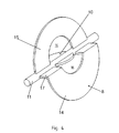
- FIG. 4 further shows the exhaust flap 8 according to the invention with integrated bypass flap 10 on a shaft 11, wherein the bypass flap 10 is pushed by a slot not shown through the shaft 11.
- the exhaust valve 8 is preferably formed in two parts, so that the upper part 15 of the exhaust valve is placed on a not shown slot of the shaft 11 and the lower part 14 of the exhaust valve 8 is coupled via the step offset 17 with the shaft 11.
- the recess 16 in the exhaust valve 8 in which the in FIG. 4 Bypass tube 6 is not shown arranged.
- the recess 16 is formed in two parts, wherein a part of the recess 16 in the upper part 15 of the exhaust valve 8 and a part of the recess 16 in the lower part 14 of the exhaust valve 8 and the step offset 17 is formed.
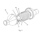
- FIG. 5 shows the inventive arrangement without exhaust flap 8, without bypass valve 10 and without shaft 11, in which case the exhaust pipe 4 and the bypass pipe 6 are arranged one inside the other.
- the bypass pipe 6 is arranged concentrically offset upwards in the exhaust pipe 4.
- this is apparent through the mounting holes 20 for carrying out the shaft 11, not shown, which are offset from a central cross-sectional profile 21 of the bypass tube 6 down.
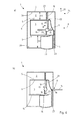
- FIGS. 6a and b explained in more detail flattening 22 of the bypass tube 6 in an upper end region. This makes it possible that the upper part 15 of the exhaust flap 8 is pivoted with the recess 16 via the end of the bypass tube 6 in the opposite direction of the exhaust gas flow direction A.
- FIGS. 6a and 6b show the exhaust valve assembly 1 according to the invention in each case in a cross-sectional view.
- the exhaust flap 8 is shown here closed by the lower part 14 and the upper part 15 of the exhaust valve 8, so that flowing into the exhaust valve assembly 1 exhaust gas can flow exclusively through the opened bypass channel 3, but not through the exhaust passage 2.
- sealing edges 23rd against which the upper part 15 and the lower part 14 of the exhaust valve 8 come to rest.
- the upper part 15 and the lower part 14 of the exhaust flaps 8 are in the axial direction 24 with respect to the sealing edges 23, so that in the radial direction 25 a game remains to different radial of the exhaust valve 8 against the inner circumferential surface 26 of the exhaust pipe 4 can be compensated.
- the previously mentioned flattening 22 is shown at the end of the bypass tube 6, wherein in execution of the rotational movement of the upper part 15 of the exhaust valve 8 it is pivoted about the flat 22.
- a bulge 27 is shown on the lower side of the exhaust pipe 4, wherein also in execution of the rotational movement of the lower part 14 of the exhaust valve 8 is pivoted by the bulge 27.
- sealing edges 23 are arranged in the form of axial abutment surfaces for the upper and the lower part 18, 19 of the bypass valve 10, so that at in FIG. 6b illustrated closed bypass valve 10, the upper part of the bypass valve 10 comes to rest on an upper sealing edge 23 and the lower part 19 of the bypass valve 10 comes to rest on a lower sealing edge 23.
- the bypass valve 10 is completely closed, whereas the exhaust valve 8 is fully open. Also visible is the upper part 15 and the lower part 14 of the recess 16 in the exhaust valve 8, which in the closed state, the outer circumferential surface 5 of the bypass tube. 6 receives. Furthermore, it is easy to see in FIG.
- FIG. 7 shows an exhaust gas heat exchanger 28 according to the invention in a perspective view.
- the exhaust gas heat exchanger 28 in this case has an outer circumferential surface 29, wherein this is welded together in its longitudinal direction 30 from different individual assemblies.
- it has a funnel-shaped connecting piece 31, which widens radially in the longitudinal direction 30, starting from a coupling point 32 with an exhaust line (not shown).
- a welding sleeve 33 is coupled to the funnel-shaped connecting piece 31, wherein the welding sleeve 33 has the exhaust flap according to the invention or it is not shown in detail in the welding sleeve 33.
- the individual assemblies, shown here, the nozzle 31 and the welding sleeve 33 are welded together by an indicated thermal joining seam 34 radially circumferentially.
- FIG. 8 illustrated is the exhaust gas heat exchanger 28 according to the invention in a perspective view.
- this welding sleeve 33 is coupled, which is substantially the structure according to the in FIGS. 6a and b The structure shown is similar. Thus, in particular, the bulge 27 on the underside of the welding sleeve 33 is shown.
- bypass flap 10 is in the in FIG. 8 shown variant open so that exhaust gas in the exhaust gas flow direction A passes through the bypass channel 3.
- the exhaust valve 8 is shown in the closed position.
- a spiral 36 is arranged, so that in the case of flow of exhaust gas through the exhaust passage 2 a not shown in detail through the spiral conduit 36 medium or fluid can be heated in cross flow through the exhaust gas.
- the spiral pipe 36, the bypass pipe 6 is arranged radially encompassing under inclusion of an insulation space 37.
- the insulation space 37 is used in bypassing the exhaust gas heat exchanger 28 by bypassing a heat transfer from the bypass line to the spiral 36.
- an air layer disposed within the scope of the invention however, insulation materials or insulation gases, in particular insulating materials can be arranged here ,
- FIG. 9 an illustration of the exhaust gas heat exchanger 28 according to the invention is shown, without welding sleeve and without jacket tube.
- an insulating tube 38 is arranged around the bypass tube 6, so that an insulation between the bypass tube 6 and spiral 36 is formed.
- a support wall 39 and a Leitfinne is arranged in the exhaust passage shown as free, wherein the partially visible exhaust flap 8 comes in execution of the rotational movement D about the rotation axis 9 on the support wall 39 to rest.
Landscapes
- Engineering & Computer Science (AREA)
- Chemical & Material Sciences (AREA)
- Combustion & Propulsion (AREA)
- Mechanical Engineering (AREA)
- General Engineering & Computer Science (AREA)
- Exhaust Silencers (AREA)
Abstract
Description
- Die vorliegende Erfindung betrifft eine Abgasklappenanordnung zur Anordnung in einem Abgasstrang eines Kraftfahrzeugs gemäß den Merkmalen im Oberbegriff von Patentanspruch 1.
- Die vorliegende Erfindung betrifft weiterhin einen Abgaswärmetauscher für ein Kraftfahrzeug gemäß den Merkmalen im Oberbegriff von Patentanspruch 14.
- In Abgasanlagen bzw. Abgasrohren von Kraftfahrzeugen mit Verbrennungskraftmaschinen sind bewegliche Klappen angeordnet um bestimmte Abschnitte der Abgasanlage ganz oder teilweise zu verschließen oder freizugeben oder den Strömungswiderstand für das Abgas in einem Abgasrohr zu erhöhen oder die Schalldämpfakustik zu beeinflussen. Die Klappen werden während des Betriebes des Kraftfahrzeugs dabei von einem Aktuator bedient, wobei der Aktuator insbesondere als pneumatisch betätigter Unterdruckaktuator ausgebildet ist. Beispielsweise ist eine solche Klappanordnung aus der
DE 10 2010 027 930 A1 bekannt. - Ferner ist es aus dem Stand der Technik bekannt, Abgase nicht direkt über die Abgasanlage in die Umwelt abzuleiten, sondern die im Abgas enthaltene Restwärme für den Betrieb des Kraftfahrzeuges zu nutzen. Beispielsweise wird die im Abgas enthaltende Restenergie zum Betreiben einer Auflademaschine genutzt oder aber die enthaltene Wärme zum Beheizen verschiedener Funktionen, beispielsweise zum Vorheizen von Schmierstoffen für Getriebe oder aber den Kurbelbetrieb der Verbrennungskraftmaschine. Ebenfalls ist es bekannt, die im Abgas enthaltene Wärmeenergie zum Beheizen des Kraftfahrzeuginnenraumes zu nutzen. Für diese Nutzungsmöglichkeiten sind insbesondere Abgaswärmetauscher bekannt, durch die das Abgas geleitet wird und dann entsprechend auf ein anderes Medium, beispielsweise Frischluft zum Klimatisieren des Fahrzeuginnenraumes, übertragen wird.
- Nach dem durchströmen des Abgases durch den Wärmetauscher wird dieses dann dem weiteren Abgasstrang wieder zugeführt und durch verschiedene Katalysatoren gereinigt und/oder durch Schalldämpfer gedämpft und anschließend an die Umwelt abgegeben. Die Durchströmung eines Wärmetauschers ist jedoch nicht zu jedem Betriebszeitpunkt gewünscht, weshalb Abgaswegeventile aus dem Stand der Technik bekannt sind, mit dem das Abgas durch verschiedene Leitungen des Abgasstranges leitbar sind. Als einfachste Ausführungsvariante ist ein solches Ventil als Y-Strömungsventil oder aber ein Dreiwegeventil bekannt, wobei das Abgas durch einen ersten Weg kommend entweder in den zweiten oder aber den dritten Weg oder aber auch in beide weiteren Wege gleichzeitig geleitet wird.
- Ferner ist aus der
EP 1 291 509 B1 ein Ventilkomponentensatz für eine interne Bypassströmung bekannt, bei der in einem äußeren Abgasstrang ein innerer Abgasstrang angeordnet ist, wobei der innere Abgasstrang durch eine Schwenkklappe öffnenbar und/oder verschließbar ist. - Die innere Abgasklappe wird dabei wiederum von einem pneumatisch betätigten Aktuator je nach Anforderung in eine Öffnungs- oder Schließstellung oder aber auch in eine Zwischenstellung verschwenkt.
- Aufgabe der vorliegenden Erfindung ist es, ausgehend vom Stand der Technik einen Abgaswärmetauscher mit einer Abgasklappenanordnung bereitzustellen, mit dem es möglich ist, strömendes Abgas in verschiedene Abgaswege zu leiten, die kompakte Außenabmessungen aufweist, besonders einfach betätigbar ist und kostengünstig herstellbar ist.
- Die zuvor genannte Aufgabe wird mit einer Abgasklappenanordnung für einen Abgasstrang eines Kraftfahrzeuges gemäß den Merkmalen in Patentanspruch 1 gelöst.
- Die zuvor genannte Aufgabe wird weiterhin mit einem Abgaswärmetauscher gemäß den Merkmalen im Patentanspruch 14 gelöst.
- Vorteilhafte Ausführungsvarianten der vorliegenden Erfindung sind Bestandteil der abhängigen Patentansprüche.
- Die erfindungsgemäße Abgasklappenanordnung für ein Abgasstrang eines Kraftfahrzeuges, wobei die Abgasklappenanordnung eine durch ein Abgasrohr ausgebildete Abgasleitung aufweist, in der konzentrisch innenliegend eine durch ein Bypassrohr ausgebildete Bypassleitung angeordnet ist, wobei das Bypassrohr durch eine drehbare Bypassklappe verschließbar ist, ist dadurch gekennzeichnet, dass die Abgasleitung durch eine drehbare Abgasklappe verschließbar ist, wobei die Abgasklappe eine Ausnehmung aufweist, in der das Bypassrohr angeordnet ist und die Bypassklappe und die Abgasklappe um eine Rotationsachse auf der gleichen Welle drehbar gelagert sind.
- Die erfindungsgemäße Abgasklappenanordnung ist somit mindestens als Dreiwegeventil ausgebildet, wobei ein von einer Verbrennungskraftmaschine kommendes Abgas auf die Abgasklappenanordnung trifft. In der Abgasklappenanordnung selbst ist außenliegend ein erster Strömungskanal mithin die Abgasleitung angeordnet ist, wobei in der Abgasleitung selber ein innenliegender zweiter Strömungskanal angeordnet ist, mithin das hier bezeichnete Bypassrohr. Es ist somit möglich, das Abgas entweder durch den außenliegenden Strömungskanal, also die Abgasleitung oder aber den innenliegenden Strömungskanal also durch das Abgasrohr zu leiten oder aber auch durch beide Strömungskanäle, wobei die jeweiligen Durchflussmengen durch die Bypassklappe oder aber die Abgasklappe einstellbar sind.
- Die erfindungsgemäße Abgasklappenanordnung ermöglicht somit eine in den äußeren Bauraumabmessung besonders kompakte Bauweise, da beide Strömungskanäle ineinanderliegend ausgebildet sind und zugleich eine gute Einstellbarkeit, da sowohl der Durchfluss durch die außenliegende Abgasleitung durch die Abgasklappe einstellbar ist, als auch der Durchfluss durch das Bypassrohr durch die Bypassklappe einstellbar ist.
- Insbesondere wird die kompakte Bauweise aufgrund der Ausnehmung in der Abgasklappe sowie das darin angeordnete Bypassrohr ermöglicht. Ferner wird durch den konzentrischen Aufbau eine verschiedenartige Anströmung der beiden Teile der Abgasklappe ermöglicht, wodurch nur geringe Stellkräfte notwendig sind um die Abgasklappe zu verstellen. Analoge Ausführungen gelten für die Bypassklappe.
- Insbesondere sind die Abgasklappe und/oder die Bypassklappe als drehbare Butterflyklappe ausgebildet. Hierzu sind die Abgasklappe und/oder die Bypassklappe drehbar um eine Rotationsachse gelagert, wobei die Bypassklappe und die Abgasklappe auf einer gleichen Welle drehbar gelagert sind. Bezüglich der gleichen Rotationsachse bedeutet dies, dass sowohl die Bypassklappe als auch die Abgasklappe die Drehbewegung um die gleiche Rotationsachse ausführen. Die Rotationsachse sitzt besonders bevorzugt auf der Mitte des Abgasrohres selber. Aufgrund des konzentrischen Versatzes des Bypassrohres gegenüber einer konzentrischen Mitte des Abgasrohres ergibt sich eine ungleiche Verteilung der Querspantfläche beider Abgasklappen, was sich wiederum vorteilig auf die Anströmung der Klappen im geschlossenen Zustand auswirkt, wodurch die Stellkräfte zum Öffnen der Klappen verringert werden.
- Weiterhin sind beide Klappen auf der gleichen Welle gelagert, so dass bei Drehung der Welle sich beispielsweise die Abgasklappe schließt und gleichzeitig die Bypassklappe öffnet oder umgekehrt. Hierdurch ist nur ein Stellaktuator notwendig um beide Klappen gleichzeitig zu bedienen. Die Klappen selber, also sowohl die Abgasklappe als auch die Bypassklappe können dabei auf die Welle aufgeschraubt sein oder aber auch zusätzlich in einen Schlitz der Welle eingeführt werden und dort kraftschlüssig beispielsweise über eine Klemmung lagefixiert werden oder aber durch zusätzliche formschlüssige Fixierung beispielsweise durch ein Verschrauben lagefixiert werden.
- Im Rahmen der Erfindung ist es ebenfalls möglich die Klappen an der Welle zu verkleben oder in sonstiger Weise zu fixieren. Zur Montage der Abgasklappenanordnung wird zunächst vorzugsweise die Welle durch entsprechende Öffnungen in der Abgasleitung und dem Bypassrohr eingeschoben und anschließend die Klappen an der Welle montiert. Im Rahmen der Erfindung ist es jedoch auch möglich die Welle in Längsrichtung zweiteilig auszubilden, so dass zunächst die Klappen in die Abgasleitung oder aber das Bypassrohr eingesetzt werden und dann von beiden Seiten die Welle eingeschoben wird und die Klappen formschlüssig in einem Aufnahmeschlitz aufgenommen werden.
- In einer weiteren bevorzugten Ausführungsvariante wird die Welle derart ausgebildet, dass die Bypassklappe und die Abgasklappe unabhängig voneinander drehbar sind. Beispielweise ist die Welle ebenfalls zweiteilig aufgeteilt, wobei diese aus einer inneren und einer äußeren Welle ausgebildet ist und somit über die innere Welle die Bypassklappe ansteuerbar ist und über die äußere Welle die Abgasklappe ansteuerbar ist. Hierdurch ist es möglich beide Strömungskanäle unabhängig voneinander zu betätigen. In diesem Fall ist es möglich die Bypassklappe und die Abgasklappe um die Rotationsachse beispielsweise in gleiche Richtung drehbar auszugestalten oder aber auch in verschiedene Richtungen drehbar zu lagern.
- Weiterhin besonders bevorzugt sind die Bypassklappe und/oder die Abgasklappe über einen Aktuator ansteuerbar, insbesondere über einen elektrischen Stellaktuator. Im Falle der Lagerung von Abgasklappe und Bypassklappe auf der gleichen Welle ist es möglich beide Klappen durch Betätigung mit nur einem Stellaktuator gleichzeitig zu verstellen. Beispielsweise kann dieser Stellaktuator als Linearantieb über eine Koppelstange mit der Welle gekoppelt sein. Im Rahmen der Erfindung ist es jedoch auch möglich insbesondere bei Verwendung eines rein elektrischen Stellaktuators ein Elektromotor direkt an die Welle zu koppeln und durch Drehbewegung des Elektromotors entsprechend eine Drehbewegung der Klappe auszuführen. Auch dieses bietet insbesondere wiederum den Vorteil, dass die erfindungsgemäße Abgasklappenanordnung ein sehr kompaktes Bauraumabmaß aufweist.
- Im Rahmen der Erfindung ist es jedoch auch bei einer zweiteiligen Welle und damit verbundene unabhängige Ansteuerbarkeit beider Klappen voneinander möglich zwei Aktuatoren zu verwenden, so dass jeder Aktuator zur Ansteuerung einer Klappe verwendet wird.
- Weiterhin besonders bevorzugt weist die Abgasklappe einen Stufenversatz auf, insbesondere ist ein unterer Teil der Abgasklappe gegenüber einem oberen Teil der Abgasklappe versetzt angeordnet, besonders bevorzugt parallel versetzt. Der Stufenversatz ist insbesondere im Bereich der Welle ausgebildet, wobei besonders bevorzugt der obere Teil der Abgasklappe direkt an der Welle angeordnet ist und der untere Teil der Abgasklappe über den Stufenversatz mit einem Versatz zu der Welle angeordnet ist. Hierdurch ergibt sich der Vorteil, dass bei Ausführung der Schwenkbewegung der mit dem Stufenversatz versetzte, insbesondere parallel versetzte untere Teil der Abgasklappe derart an eine Unterseite des Bypassrohr schwenkbar ist, dass die Klappe im Wesentlichen vollständig parallel zur Strömungsrichtung gelagert werden kann und hierdurch eine maximale Querschnittsfläche der Abgasleitung zur Durchströmung mit Abgas freigegeben wird. Ferner ist die Ausnehmung zur Durchführung des Bypassrohres durch die Abgaskappe im Bereich des Stufenversatzes angeordnet, so dass die Bypassklappe um ein Ende des Bypassrohres schwenkbar ist und von einer geschlossen Stellung in der nahezu die gesamte, vorzugsweise vollständig zur Verfügung stehende Strömungsfläche der Abgasleitung geschlossen ist und in einer Öffnungsstellung ein maximaler Durchtritt durch die Abgasleitung freigegeben wird.
- Weiterhin besonders bevorzugt weist der untere Teil der Abgasklappe gegenüber dem oberen Teil der Abgasklappe eine größere Querschnittsfläche auf. Besonders bevorzugt wird der untere Teil der Abgasklappe bei Ausführung der Drehbewegung um die Rotationsachse in Strömungsrichtung des Abgases geschwenkt und der obere Teil der Abgasklappe entgegen der Strömungsrichtung des Abgases. Dadurch dass der untere Teil der Abgasklappe eine größere Querschnittsfläche, mithin Querspantfläche aufweist, trifft hier mehr strömendes Abgas auf die Querschnittsfläche, als im oberen Teil. Hierdurch ist der untere Teil mit einer größeren Kraft beaufschlagt, als der obere Teil, wodurch sich die Abgasklappe in Strömungsrichtung des Abgases leichter öffnen lässt. Sofern das Verhältnis der unterschiedlichen Größenverteilung vom oberen Teil zum unteren Teil der Abgasklappe im Rahmen gehalten wird, ist es jedoch auch möglich die Schließbewegung besonders einfach auszuführen. Hierdurch ergibt sich der Vorteil, dass der Aktuator nur geringe Stellkräfte benötigt um die Drehbewegung der Abgasklappe durchzuführen.
- In einer weiteren bevorzugten Ausführungsvariante ist die Bypassklappe ebenfalls asymmetrisch unterteilt, so dass der obere Teil der Bypassklappe gegenüber dem unteren Teil Der Bypassklappe eine größere Querschnittsfläche aufweist. Bei Öffnen der Bypassklappe wird insbesondere der obere Teil in Richtung der Abgasströmungsrichtung geschwenkt, wohingegen der untere Teil entgegen der Abgasströmungsrichtung geschwenkt wird. Insbesondere im Zusammenspiel mit der Abgasklappe und ganz besonders bevorzugt bei Verschwenken beider Klappen in Ausführung einer Drehbewegung ist somit der untere Teil der Abgasklappe und der obere Teil der Bypassklappe jeweils mit einer größeren Querschnittsfläche beaufschlagt, wodurch sich die Stellkräfte bei strömendem Abgas derart neutralisieren, dass nur eine geringe Stellkraft zur Schwenkbewegung der Gesamtklappe mithin beider Klappen gleichzeitig notwendig ist.
- Weiterhin bevorzugt weist der untere Abschnitt des Abgaskanals eine Schwenkausnehmung, insbesondere eine Ausbauchung auf, wobei bei Ausführung der Drehbewegung der Abgasklappe der untere Teil der Abgasklappe durch die Schwenkausnehmung schwenkbar ist. Die Schwenkausnehmung ist insbesondere in Form einer Ausbauchung gegenüber einer inneren Mantelfläche der Abgasleitung in radialer Richtung nach außen überstehend ausgebildet. Die aufgrund des Stufenversatzes in radialer Richtung sich erstreckende Schwenkbewegung des unteren Teils der Abgasklappe wird durch die Schwenkausnehmung ausgeglichen, so dass es zu keinem Verkanten der Abgasklappenanordnung kommt.
- Weiterhin bevorzugt ist der Bypasskanal gegenüber der Bypassklappe überstehend ausgebildet, wobei bevorzugt ein oberer Abschnitt des Bypasskanals gegenüber einem unteren Abschnitt geringer überstehend ausgebildet ist. Hierdurch ist es möglich zum einen eine Abdichtung auch bei nur um wenige Grad verschwenkter Abgasklappe noch zu gewährleisten, so dass die Abgasleitung im Wesentlichen nicht strömungsleitend angeordnet ist. Ferner ist der Verlauf zwischen oberem geringer überstehenden Abschnitt des Bypasskanals gegenüber unterem Abschnitt des Bypasskanals, der gegenüber dem oberen Abschnitt weiter überstehend ausgebildet ist und des Stufenversatzes möglich, die Abgasklappe abzudichten. Der Stufenversatz zeigt somit ausgehend von der drehbaren Welle in Richtung zur Abgasströmung und auch zum überstehenden unteren Abschnitt, wodurch bei geschlossener Abgasklappe die Ausnehmung der Abgasklappe an dem unteren Abschnitt des Bypassrohres anliegend angeordnet ist.
- Ferner ist bevorzugt der obere Abschnitt des Bypasskanals an einer Außenseite abflachend ausgebildet, so dass bei Ausführung der Schwenkbewegung der Abgasklappe diese über die abgeflachte Außenseite gleiten kann. Ferner ist besonders bevorzugt eine Stirnseite der Bypassöffnung des Bypasskanals von oben nach unten verlaufend zunehmend gegenüber der Bypassklappe überstehend ausgebildet, wobei der Verlauf insbesondere progressiv zunehmend ausgebildet ist.
- Weiterhin besonders bevorzugt ist die Bypassklappe und/oder die Abgasklappe selbst als runde, elliptische und/oder rechteckige Klappe ausgebildet. Dies bedeutet, dass die äußere Kontur der jeweiligen Klappe bevorzugt rund, elliptisch, oder aber auch rechteckig ausgebildet ist. Abhängig ist dies von den zu wählenden Querschnitten der strömungsleitenden Kanäle. Im Rahmen der Erfindung ist es auch möglich eine jeweils mehreckige Ausführung beispielsweise ein Fünf- oder aber auch Sechseck oder anderweitiges Vieleck oder aber auch Mischformen der zuvor benannten Klappenkonturen zu wählen.
- Weiterhin bevorzugt ist die Welle an beiden Seiten gelagert, wobei insbesondere die Lager außerhalb des Abgasrohres selber angeordnet sind, so dass sie nicht der direkten Temperatureinwirkung des strömenden Abgases ausgesetzt sind. Ebenfalls sind die Lagerungen nicht, durch im Abgas enthaltene Schmutz- oder Rußpartikeln, einer Verschmutzung ausgesetzt. Die Lager selbst sind besonders bevorzugt als Gleitlager und/oder Wälzlager, ganz besonders bevorzugt als keramisches Lager ausgebildet.
- Weiterhin bevorzugt ist zwischen den Klappen und den die Klappen jeweils umgebenden Innenmantelflächen ein Dehnungsspalt vorgesehen, so dass bei unterschiedlichen thermischen Ausdehnungen von Klappe zu Rohr oder aber Innenmantelfläche ein Verklemmen der Klappen vermieden wird. Weiterhin besonders bevorzugt sind zur Steigerung der Dichtigkeit der Abgasklappenanordnung Dichtkanten vorgesehen, so dass die Abgasklappe und/oder die Bypassklappe an einer jeweiligen Dichtkante zur Anlage kommen und den jeweiligen Strömungskanal im Wesentlichen gasdicht abschließen.
- Weiterhin besonders bevorzugt sind entweder die Dichtkanten in dem Kanal selber und/oder die Dichtkanten an der jeweiligen Klappe angeordnet. Die Dichtkanten sind besonders bevorzugt in Abgasströmungsrichtung derart angeordnet, dass sie eine radiale Ausdehnung der Klappen zu der Innenmantelfläche des jeweiligen Rohres kompensieren, ohne dabei Nachteile bei der Gasdichtigkeit zu verursachen. Die Dichtkanten sind dabei besonders bevorzugt aus einem metallischen oder aber keramischen Werkstoff hergestellt, so dass sie den zu erwartenden Abgastemperaturen standhalten und gleichzeitig eine gasdichte Funktion ausbilden. Besonders bevorzugt sind die Dichtkanten derart ausgebildet, dass ein Festkleben oder Festbacken der Klappen an den Dichtkanten vermieden wird. Insbesondere können die Dichtkanten dazu auch beschichtet sein.
- Die vorliegende Erfindung sieht weiterhin einen Abgaswärmetauscher vor, wobei der Abgaswärmetauscher in einem Abgasstrang eines Kraftfahrzeuges angeordnet wird. Der Abgaswärmetauscher ist hierzu als geschweißtes Blechbauteil, insbesondere als rohrförmiges Bauteil ausgebildet und weist mindestens zwei rohrförmig ineinander verschachtelte Kanäle auf, wobei er sich erfindungsgemäß dadurch auszeichnet, dass er eine Abgasklappenanordnung mit mindestens einem der zuvor beschriebenen Merkmale besitzt.
- Besonders bevorzugt ist der Abgaswärmetauscher aus einem metallischen Werkstoff, insbesondere aus einem Edelstahl ausgebildet, so dass er resistente Eigenschaften gegen das mitunter hochkorrosive Abgas aufweist. Der erfindungsgemäße Abgaswärmetauscher ist weiterhin insbesondere rohrförmig ausgebildet, wobei ein außenliegender Abgaskanal einen innenliegenden rohrförmigen Bypasskanal aufweist und die beiden Kanäle durch die erfindungsgemäße Abgasklappe jeweils unterschiedlich oder aber gleichzeitig zu Teilströmen anströmbar sind. In dem Abgaskanal selbst ist besonders bevorzugt ein Spiralwärmetauscher angeordnet, durch den ein Medium strömbar bzw. leitbar ist, dass durch das Abgas, welches durch den Abgaskanal strömt erwärmbar ist.
- Insbesondere ist der erfindungsgemäße Abgaswärmetauscher derart als Schweißbauteil ausgebildet, dass sich die Abgasklappenanordnung in einer Schweißhülse befindet, die in Längsrichtung in einer Außenmantelfläche des Abgaswärmetauschers eingegliedert ist. Hierdurch erfolgt eine besonders kostengünstige Produktion des erfindungsgemäßen Abgaswärmetauschers, wobei zugleich aufgrund der rohrförmig ineinander verschachtelten zwei Kanäle geringe Außenabmessungen und auch gleichzeitig geringer Materialeinsatz erreicht werden.
- Weiterhin bevorzugt ist das Bypassrohr über eine Stützwand in dem Abgasrohr gelagert. Die Stützwand stellt somit einen konstanten Abstand zwischen Außenmantelfläche des Bypassrohres und Innenmantelfläche des Abgasrohrs ein, wobei die Stützwand bevorzugt nur an einer der beiden zuvor genannten Flächen lagefixiert bzw. fest gekoppelt ist und gegenüber der anderen Fläche gleitend gelagert ist. Hierdurch können Längenänderungen von Bypassrohr und/oder Abgasrohr derart kompensiert werden, dass ein Abstand in Radialrichtung durch die Stützwand gehalten ist, jedoch in Axialrichtung sich die Längen der Rohre relativ zueinander ändern können, ohne dass der Abgaswärmetauscher aufgrund eines Verzuges in einen Spannungszustand überführt wird.
- Weitere Vorteile, Merkmale, Eigenschaften und Aspekte der vorliegenden Erfindung sind Bestandteil der nachfolgenden Beschreibung. Die Ausführungsvarianten sind mit schematischen Figuren dargestellt. Diese dienen dem einfachen Verständnis der Erfindung. Es zeigen:
- Figur 1
- eine perspektivische Ansicht einer Abgasklappenanordnung mit geschlossener Abgasklappe und geöffneter Bypassklappe,
- Figur 2
- eine perspektivische Ansicht aus
Figur 1 mit teilgeöffneter Abgasklappe und teilgeöffneter Bypassklappe, - Figur 3
- die gleiche perspektivische Ansicht mit geöffneter Abgasklappe und geschlossener Bypassklappe,
- Figur 4
- eine erfindungsgemäße Abgasklappe in Detailansicht,
- Figur 5
- eine perspektivische Ansicht des Abgasrohres und des Bypassrohres ohne Abgasklappe,
- Figur 6a und b
- eine Querschnittsansicht durch die erfindungsgemäße Abgas-klappenanordnung mit geöffneter und geschlossener Abgasklappe sowie geschlossener und geöffneter Bypassklappe,
- Figur 7
- einen erfindungsgemäßen Abgaswärmetauscher in perspektivischer Teilansicht,
- Figur 8
- einen erfindungsgemäßen Abgaswärmetauscher in perspektivischer Schnittansicht und
- Figur 9
- einen erfindungsgemäßen Abgaswärmetauscher in Darstellung ohne Außenmantelfläche.
- In den Figuren werden für gleiche oder ähnliche Bauteile dieselben Bezugszeichen verwendet, auch wenn eine wiederholte Beschreibung aus Vereinfachungsgründen entfällt.
-
Figur 1 zeigt eine erfindungsgemäße Abgasklappenanordnung 1, wobei die Abgasklappenanordnung 1 ausgebildet ist aus einem außenliegenden Abgaskanal 2 und einem innenliegenden Bypasskanal 3. Der Abgaskanal 2 selbst wird durch ein außenliegendes Abgasrohr 4 begrenzt sowie durch die Außenmantelfläche 5 eines innenliegenden Bypassrohres 6. Der Bypasskanal 3 selbst liegt in dem Bypassrohr 6 und wird durch die Innenmantelfläche 7 des Bypassrohres 6 begrenzt. In dem Abgaskanal 2 ist eine Abgasklappe 8 um eine Rotationsachse 9 drehbar angeordnet, wobei in dem Bypasskanal 3 um die gleiche Rotationsachse 9 eine Bypassklappe 10 drehbar angeordnet ist. - Beide Klappen 8, 10 sind auf einer Welle 11 angeordnet, wobei die Welle 11 an ihren Enden 12 in jeweiligen Lagern 13 drehbar gelagert ist. Die Lager 13 sind dabei außerhalb des Abgasrohres 4 angeordnet, so dass sie nicht den thermischen oder aber hochkorrosiven Belastungen des durch den Abgaskanal 2 strömenden Abgases ausgesetzt sind.
- In der in
Figur 1 dargestellten Ausführungsvariante ist die Abgasklappe 8 im geschlossenen Zustand dargestellt und die Bypassklappe 10 in geöffnetem Zustand. Ein unterer Teil 14 der Abgasklappe 8 ist dabei in seiner Querschnittsfläche größer ausgebildet, als ein oberer Teil 15 der Abgasklappe 8. Die Abgasklappe 8 weist ferner eine Ausnehmung 16 auf, die die Außenmantelfläche 5 des Bypassrohres 6 nahezu vollständig umschließt. Ferner ist in der Abgasklappe 8 ein Stufenversatz 17 ausgebildet, so dass der untere Teil 14 in Abgasströmungsrichtung A versetzt gegenüber dem oberen Teil 15 der Abgasklappe 8 versetzt ausgebildet ist. Oberer und unterer Teil 14, 15 der Abgasklappe 8 verlaufen in der hier dargestellten Ausführungsvariante parallel. - In
Figur 2 wird um die Rotationsachse 9 eine Drehbewegung D der Welle 11 ausgeführt, so dass sich beide Klappen gleichzeitig drehen. Dabei sind hier beide Klappen derart geschwenkt, dass sowohl der Abgaskanal 2 teilgeöffnet ist, als auch der Bypasskanal 3 teilgeöffnet ist. -
Figur 3 zeigt die gleiche Anordnung nach Abschluss der Drehbewegung D, so dass hier dargestellt der Bypasskanal 3 vollständig geschlossen ist und der Abgaskanal 2 vollständig geöffnet ist. Der obere Teil 18 der Bypassklappe 10 ist dabei bezogen auf die Abgasströmungsrichtung in Richtung zur Abgasströmungsrichtung geschwenkt und der untere Teil 14 der Abgasklappe 8 ist in Strömungsrichtung des Abgases geschwenkt. Bei Ausführung der Schließbewegung schwenkt ein oberer Teil 18 der Bypassklappe 10 entgegengesetzt zur Strömungsrichtung des Abgases und ein unterer Teil 19 der Bypassklappe 10 schwenkt in Strömungsrichtung des Abgases. Auch bei der Bypassklappe 10 ist der obere Teil 18 derart größer ausgebildet, dass sich ein asymmetrisches Verhältnis zwischen oberem und unterem Teil 18, 19 der Bypassklappe 10 ergibt. Mithin sind der obere Teil 18 der Bypassklappe 10 größer ausgebildet und der untere Teil 14 der Abgasklappe 8. Bei einer Schwenkbewegung relativieren sich somit, insbesondere neutralisieren sich die entstehenden Kräfte, die durch das auf die jeweiligen Teile der Abgas- oder Bypassklappe 8, 10 treffende Abgasströmung verursacht werden. -
Figur 4 zeigt weiterhin die erfindungsgemäße Abgasklappe 8 mit integrierter Bypassklappe 10 auf einer Welle 11, wobei die Bypassklappe 10 durch einen nicht näher dargestellten Schlitz durch die Welle 11 geschoben wird. Die Abgasklappe 8 ist bevorzugt zweiteilig ausgebildet, so dass der obere Teil 15 der Abgasklappe auf einen ebenfalls nicht näher dargestellten Schlitz der Welle 11 aufgesetzt ist und der untere Teil 14 der Abgasklappe 8 über den Stufenversatz 17 mit der Welle 11 gekoppelt ist. Ferner dargestellt ist die Ausnehmung 16 in der Abgasklappe 8, in der das inFigur 4 nicht näher dargestellte Bypassrohr 6 angeordnet ist. Die Ausnehmung 16 ist zweiteilig ausgebildet, wobei sich ein Teil der Ausnehmung 16 im oberen Teil 15 der Abgasklappe 8 und ein Teil der Ausnehmung 16 in dem unteren Teil 14 der Abgasklappe 8 sowie dem Stufenversatz 17 ausgebildet ist. -
Figur 5 zeigt die erfindungsgemäße Anordnung ohne Abgasklappe 8, ohne Bypassklappe 10 und ohne Welle 11, wobei hier das Abgasrohr 4 sowie das Bypassrohr 6 ineinander angeordnet sind. Erkennbar ist, dass das Bypassrohr 6 konzentrisch nach oben versetzt in dem Abgasrohr 4 angeordnet ist. Insbesondere ersichtlich ist dies durch die Montageöffnungen 20 zur Durchführung der nicht näher dargestellten Welle 11, die gegenüber einem Mittenquerschnittsverlauf 21 des Bypassrohres 6 nach unten versetzt sind. Ferner erkennbar ist eine in denFiguren 6a und b näher erläuterte Abflachung 22 des Bypassrohres 6 in einem oberen Endbereich. Hierdurch ist es möglich, dass der obere Teil 15 der Abgasklappe 8 mit der Ausnehmung 16 über das Ende des Bypassrohres 6 in entgegengesetzter Richtung der Abgasströmungsrichtung A geschwenkt wird. -
Figur 6a und 6b zeigen die erfindungsgemäße Abgasklappenanordnung 1 jeweils in einer Querschnittsansicht. InFigur 6a ist die Abgasklappe 8 hier dargestellt durch den unteren Teil 14 sowie den oberen Teil 15 der Abgasklappe 8 geschlossen, so dass in die Abgasklappenanordnung 1 einströmendes Abgas ausschließlich durch den geöffneten Bypasskanal 3 strömen kann, nicht jedoch durch den Abgaskanal 2. Ferner dargestellt sind Dichtkanten 23, gegenüber denen der obere Teil 15 und der untere Teil 14 der Abgasklappe 8 zur Anlage kommen. Der obere Teil 15 und der untere Teil 14 der Abgasklappen 8 liegen in axialer Richtung 24 gegenüber den Dichtkanten 23 an, so dass in radialer Richtung 25 ein Spiel verbleibt, um unterschiedliche radiale der Abgasklappe 8 gegenüber der Innenmantelfläche 26 des Abgasrohres 4 kompensiert werden. Ferner ist die bereits zuvor angesprochene Abflachung 22 am Ende des Bypassrohres 6 dargestellt, wobei bei Ausführung der Drehbewegung des oberen Teils 15 der Abgasklappe 8 diese über die Abflachung 22 geschwenkt wird. - Ferner ist an der unteren Seite des Abgasrohres 4 eine Ausbauchung 27 dargestellt, wobei ebenfalls bei Ausführung der Drehbewegung der untere Teil 14 der Abgasklappe 8 durch die Ausbauchung 27 geschwenkt wird.
- Ebenfalls sind Dichtkanten 23 in Form von axialen Anschlagflächen für den oberen und den unteren Teil 18, 19 der Bypassklappe 10 angeordnet, so dass bei in
Figur 6b dargestellter geschlossener Bypassklappe 10 der obere Teil der Bypassklappe 10 an einer oberen Dichtkante 23 zur Anlage kommt und der untere Teil 19 der Bypassklappe 10 an einer unteren Dichtkante 23 zur Anlage kommt. Die Bypassklappe 10 ist dabei vollständig geschlossen, wohingegen die Abgasklappe 8 vollständig geöffnet ist. Ebenfalls zu erkennen ist der obere Teil 15 und der untere Teil 14 der Ausnehmung 16 in der Abgasklappe 8, der im geschlossenen Zustand die Außenmantelfläche 5 des Bypassrohres 6 aufnimmt. Weiterhin gut zu erkennen ist inFigur 6a der konzentrische Versatz des Bypassrohres 6 innerhalb des Abgasrohres 4, wodurch sich ein kleinerer Abstand x1 von Außenmantelfläche 5 des Bypassrohres 6 zur Innenmantelfläche 26 des Abgasrohres 4 ergibt, gegenüber dem Abstand x2 ebenfalls von Außenmantelfläche 5 des Bypassrohres 6 zur Innenmantelfläche 26 des Abgasrohres 4. Die Rotationsachse 9 selbst ist jedoch mittig in dem Abgasrohr 4 angeordnet und außermittig in dem Bypassrohr 6. Hierdurch ergeben sich die verschiedenen Höhenverhältnisse zwischen unterem Teil 14, 19 und oberen Teil 15, 18 von Abgasklappe 8 und Bypassklappe 10. -
Figur 7 zeigt einen erfindungsgemäßen Abgaswärmetauscher 28 in einer perspektivischen Ansicht. Der Abgaswärmetauscher 28 weist dabei eine Außenmantelfläche 29 auf, wobei dieser in seiner Längsrichtung 30 aus verschiedenen einzelnen Baugruppen miteinander verschweißt ist. So weist er eingangs einen trichterförmigen Stutzen 31 auf, der sich in Längsrichtung 30 beginnend von einer Koppelstelle 32 mit einem nicht näher dargestellten Abgasstrang, radial aufweitet. An dem trichterförmigen Stutzen 31 ist eine Schweißhülse 33 gekoppelt, wobei die Schweißhülse 33 die erfindungsgemäße Abgasklappe aufweist bzw. diese in der Schweißhülse 33 nicht näher dargestellt angeordnet ist. Zu erkennen sind die außenliegenden Lager 13 sowie die Welle 11, um die die Abgasklappe drehbar gelagert ist. Die einzelnen Baugruppen, hier dargestellt die Stutzen 31 und die Schweißhülse 33 sind über eine angedeutete thermische Fügenaht 34 radial umlaufend miteinander verschweißt. - In
Figur 8 dargestellt ist der erfindungsgemäße Abgaswärmetauscher 28 in einer perspektivischen Darstellung. Zu erkennen ist wiederrum die Koppelstelle 32 zur Koppelung eines nicht näher dargestellten Abgasrohres und der sich von der Koppelstelle 32 aus erstreckende radial aufweitende Stutzen 31. An diesem ist eine Schweißhülse 33 gekoppelt, die im Wesentlichen dem Aufbau gemäß dem inFigur 6a und b dargestellten Aufbau gleicht. So ist insbesondere die Ausbauchung 27 an der Unterseite der Schweißhülse 33 dargestellt. - Im weiteren Verlauf dargestellt ist das Hüllrohr 35 des außenliegenden Abgaskanals, wobei in dem Abgaskanal 2 rohrförmig eingeschlossen der Bypasskanal 3 verläuft. Die Bypassklappe 10 ist in der in
Figur 8 dargestellten Variante auf offen gestellt, so dass Abgas in Abgasströmungsrichtung A durch den Bypasskanal 3 verläuft. Hierzu ist die Abgasklappe 8 in geschlossen Stellung dargestellt. - In dem Abgaskanal 2 selbst ist eine Spiralleitung 36 angeordnet, so dass im Falle von Durchströmen von Abgas durch den Abgaskanal 2 ein durch die Spiralleitung 36 strömendes nicht näher dargestelltes Medium oder Fluid im Kreuzstrom durch das Abgas erwärmbar ist. Ferner ist die Spiralleitung 36 das Bypassrohr 6 radial umgreifend unter Eingliederung eines Isolationsraumes 37 angeordnet. Der Isolationsraum 37 dient bei Umgehung des Abgaswärmetauschers 28 durch den Bypass einer Unterbindung eines Wärmeüberganges von der Bypassleitung an die Spiralleitung 36. Vorzugsweise ist in dem Isolationsraum 37 eine Luftschicht angeordnet, im Rahmen der Erfindung können hier jedoch auch Isolationsmaterialien oder aber Isolationsgase insbesondere Isolierwerkstoffe angeordnet sein.
- In
Figur 9 ist eine Darstellung des erfindungsgemäßen Abgaswärmetauschers 28 gezeigt, ohne Schweißhülse und ohne Hüllrohr. Hier ist gut zu erkennen, dass ein Isolierrohr 38 um das Bypassrohr 6 angeordnet ist, so dass eine Isolierung zwischen Bypassrohr 6 und Spiralleitung 36 ausgebildet ist. Ferner ist eine Stützwand 39 bzw. eine Leitfinne in dem als frei dargestellten Abgaskanal angeordnet, wobei die zum Teil sichtbare Abgasklappe 8 bei Ausführung der Drehbewegung D um die Rotationsachse 9 an der Stützwand 39 zur Auflage kommt. -
- 1 -
- Abgasklappenanordnung
- 2 -
- Abgaskanal
- 3 -
- Bypasskanal
- 4 -
- Abgasrohr
- 5 -
- Außenmantelfläche zu 6
- 6 -
- Bypassrohr
- 7 -
- Innenmantelfläche zu 6
- 8 -
- Abgasklappe
- 9 -
- Rotationsachse
- 10 -
- Bypassklappe
- 11 -
- Welle
- 12 -
- Ende zu 11
- 13 -
- Lager
- 14 -
- unterer Teil zu 8
- 15 -
- oberer Teil zu 8
- 16 -
- Ausnehmung
- 17 -
- Stufenversatz
- 18 -
- oberer Teil zu 10
- 19 -
- unterer Teil zu 10
- 20 -
- Montageöffnung
- 21 -
- Mittenquerschnittsverlauf zu 6
- 22 -
- Abflachung zu 6
- 23 -
- Dichtkante
- 24 -
- axiale Richtung
- 25 -
- radiale Richtung
- 26 -
- Innenmantelfläche zu 4
- 27 -
- Ausbauchung zu 4
- 28 -
- Abgaswärmetauscher
- 29 -
- Außenmantelfläche
- 30 -
- Längsrichtung zu 28
- 31 -
- Stutzen
- 32 -
- Koppelstelle
- 33 -
- Schweißhülse
- 34 -
- Fügenaht
- 35 -
- Hüllrohr
- 36 -
- Spiralleitung
- 37 -
- Isolationsraum
- 38 -
- Isolierrohr
- 39 -
- Stützwand
- D -
- Drehbewegung
- A -
- Abgasströmungsrichtung
- x -
- Abstand
- x1 -
- Abstand
- x2 -
- Abstand
Claims (17)
- Abgasklappenanordnung (1) für einen Abgasstrang eines Kraftfahrzeuges, wobei die Abgasklappenanordnung (1) einen durch ein Abgasrohr (4) ausgebildeten Abgaskanal (2) aufweist, in dem konzentrisch innenliegend ein durch ein Bypassrohr (6) ausgebildeter Bypasskanal (3) angeordnet ist, wobei das Bypassrohr (6) durch eine drehbare Bypassklappe (10) verschließbar ist, dadurch gekennzeichnet, dass das Abgasrohr (4) durch eine drehbare Abgasklappe (8) verschließbar ist, wobei die Abgasklappe (8) eine Ausnehmung (16) aufweist, in der das Bypassrohr (6) angeordnet ist und die Bypassklappe (10) und die Abgasklappe (8) um eine Rotationsachse (9) auf der gleichen Welle (11) drehbar gelagert sind.
- Abgasklappenanordnung nach Anspruch 1, dadurch gekennzeichnet, dass die Abgasklappe (8) und/oder die Bypassklappe (10) als drehbare Butterflyklappe ausgebildet sind.
- Abgasklappenanordnung nach einem der vorhergehenden Ansprüche, dadurch gekennzeichnet, dass die Bypassklappe (10) und/oder die Abgasklappe (8) über einen Aktuator ansteuerbar sind, insbesondere über einen elektrischen Stellaktuator.
- Abgasklappenanordnung nach einem der vorhergehenden Ansprüche, dadurch gekennzeichnet, dass die Abgasklappe (8) einen Stufenversatz (17) aufweist, insbesondere ist ein unterer Teil (14) der Abgasklappe (8) gegenüber einem oberen Teil (15) der Abgasklappe (8) versetzt angeordnet ist, insbesondere parallelversetzt.
- Abgasklappenanordnung nach einem der vorhergehenden Ansprüche, dadurch gekennzeichnet, dass der untere Teil (14) der Abgasklappe (8) gegenüber dem oberen Teil (15) eine größere Querschnittsfläche aufweist.
- Abgasklappenanordnung nach einem der vorhergehenden Ansprüche, dadurch gekennzeichnet, dass der untere Teil der Abgasklappe (8) bei Ausführung der Drehbewegung (D) um die Rotationsachse in Strömungsrichtung (A) des Abgases schwenkbar ist, wobei der obere Teil der Abgasklappe entgegen der Strömungsrichtung (A) des Abgases schwenkbar ist und/oder der obere Teil (19) der Bypassklappe (10) bei Ausführung der Drehbewegung (D) um die Rotationsachse (9) in Strömungsrichtung (A) des Abgases schwenkbar ist, wobei der untere Teil (19) der Bypassklappe (10) entgegen der Strömungsrichtung (A) des Abgases schwenkbar ist.
- Abgasklappenanordnung nach einem der vorhergehenden Ansprüche, dadurch gekennzeichnet, dass in einem unteren Abschnitt des Abgaskanals (2) eine Schwenkausnehmung, insbesondere eine Ausbauchung (27) ausgebildet ist, wobei bei Ausführung der Drehbewegung (D) der untere Teil (14) der Abgasklappe (8) durch die Schwenkausnehmung schwenkbar ist.
- Abgasklappenanordnung nach einem der vorhergehenden Ansprüche, dadurch gekennzeichnet, dass das Bypassrohr (6) gegenüber der Bypassklappe (10) überstehend ausgebildet ist, wobei bevorzugt ein oberer Abschnitt des Bypasskanals (3) gegenüber einem unteren Abschnitt geringer überstehend ausgebildet ist.
- Abgasklappenanordnung nach einem der vorhergehenden Ansprüche, dadurch gekennzeichnet, dass der obere Abschnitt des Bypassrohres (6) an einer Außenseite abflachend und/oder als Freischnitt ausgebildet ist.
- Abgasklappenanordnung nach einem der vorhergehenden Ansprüche, dadurch gekennzeichnet, dass eine Stirnseite des Bypassrohres (6) von oben nach unten verlaufend zunehmend gegenüber der Bypassklappe (10) überstehend ausgebildet ist, wobei insbesondere der Verlauf, progressiv zunehmend ausgebildet ist.
- Abgasklappenanordnung nach einem der vorhergehenden Ansprüche, dadurch gekennzeichnet, dass die Bypassklappe (10) und/oder die Abgasklappe (8) eine runde, elliptische und/oder rechteckige Kontur aufweisen.
- Abgasklappenanordnung nach einem der vorhergehenden Ansprüche, dadurch gekennzeichnet, dass die Welle (11) an beiden Seiten gelagert ist, insbesondere sind die Lager (13) außerhalb des Abgasrohres (4) angeordnet.
- Abgasklappenanordnung nach einem der vorhergehenden Ansprüche, dadurch gekennzeichnet, dass die Abgasklappe (8) und/oder die Bypassklappe (10) im geschlossenen Zustand an einer Dichtkante (23) zur Anlage kommen und/oder dass die Bypassklappe (10) und/oder die Abgasklappe (8) eine Dichtkante (23) aufweisen.
- Abgaswärmetauscher (28) für ein Kraftfahrzeug, wobei der Abgaswärmetauscher in einen Abgasstrang eines Kraftfahrzeuges eingliederbar ist und als geschweißtes Blechbauteil ausgebildet ist und mindestens zwei rohrförmig ineinander verschachtelte Kanäle (2, 3) aufweist, dadurch gekennzeichnet, dass in dem Abgaswärmetauscher (28) eine Abgasklappenanordnung (1) nach mindestens Anspruch 1 angeordnet ist.
- Abgaswärmetauscher nach Anspruch 14, dadurch gekennzeichnet, dass die Abgasklappenanordnung (1) in einer Schweißhülse (33) angeordnet ist, wobei die Schweißhülse (33) in Längsrichtung (30) einen Teil der Außenmantelfläche des Abgaswärmetauschers (28) ausbildet.
- Abgaswärmetauscher nach Anspruch 14 oder 15, dadurch gekennzeichnet, dass der Abgaswärmetauscher (28) einen außenliegenden rohrförmigen Abgaskanal (2) aufweist und einen in dem Abgaskanal (2) liegenden rohrförmigen Bypasskanal (3), wobei in dem Abgaskanal (2) eine Spiralleitung (36) ausgebildet ist, zur Durchführung eines durch das Abgas zu erwärmenden Fluides.
- Abgaswärmetauscher nach einem der Ansprüche 14 bis 16, dadurch gekennzeichnet, dass an dem Bypassrohr (6) eine Stützwand (39) angeordnet ist, wobei das Bypassrohr (6) über die Stützwand (39) in dem Abgasrohr (4) gelagert ist.
Applications Claiming Priority (1)
| Application Number | Priority Date | Filing Date | Title |
|---|---|---|---|
| DE102012106888.7A DE102012106888B4 (de) | 2012-07-30 | 2012-07-30 | Abgasklappenanordnung mit integriertem Bypass |
Publications (2)
| Publication Number | Publication Date |
|---|---|
| EP2693011A1 true EP2693011A1 (de) | 2014-02-05 |
| EP2693011B1 EP2693011B1 (de) | 2016-03-02 |
Family
ID=48748008
Family Applications (1)
| Application Number | Title | Priority Date | Filing Date |
|---|---|---|---|
| EP13175783.3A Not-in-force EP2693011B1 (de) | 2012-07-30 | 2013-07-09 | Abgasklappenanordnung mit integriertem Bypass |
Country Status (2)
| Country | Link |
|---|---|
| EP (1) | EP2693011B1 (de) |
| DE (1) | DE102012106888B4 (de) |
Cited By (8)
| Publication number | Priority date | Publication date | Assignee | Title |
|---|---|---|---|---|
| EP2942500A1 (de) * | 2014-05-07 | 2015-11-11 | Benteler Automobiltechnik GmbH | Abgaswärmetauscher mit bypassrohr |
| EP3121401A4 (de) * | 2014-03-20 | 2017-11-22 | Yanmar Co., Ltd. | Abgasreinigungssystem für ein schiff |
| EP3293379A1 (de) * | 2016-09-12 | 2018-03-14 | Volvo Car Corporation | Kombinierter wärmetauscher und auspuffschalldämpfer |
| US10731608B2 (en) * | 2018-01-26 | 2020-08-04 | Futaba Industrial Co., Ltd. | Exhaust heat recovery device |
| US11105233B2 (en) | 2019-01-30 | 2021-08-31 | Toyota Motor North America, Inc. | Systems and methods for regulating performance characteristics of an exhaust system with a tri-modal valve |
| CN113551045A (zh) * | 2021-06-15 | 2021-10-26 | 吕志翼 | 一种设置有沥青烟气专用保温阀门 |
| CN113700874A (zh) * | 2021-08-31 | 2021-11-26 | 西安西热节能技术有限公司 | 一种调节管道局部流速的自启闭瓣片装置及其工作方法 |
| CN116906594A (zh) * | 2023-09-12 | 2023-10-20 | 山东天成阀门制造有限公司 | 一种带有流量调节装置的大口径蝶阀 |
Families Citing this family (1)
| Publication number | Priority date | Publication date | Assignee | Title |
|---|---|---|---|---|
| DE102014207576A1 (de) * | 2014-04-22 | 2015-11-05 | Mahle International Gmbh | Absperrvorrichtung |
Citations (6)
| Publication number | Priority date | Publication date | Assignee | Title |
|---|---|---|---|---|
| EP0699827A1 (de) * | 1994-08-29 | 1996-03-06 | Isuzu Ceramics Research Institute Co., Ltd. | Dieselpartikelfiltervorrichtung |
| EP1291509B1 (de) | 2001-08-31 | 2006-10-18 | Siemens Aktiengesellschaft | Ventilkomponentensatz für interne Bypass-Strömung |
| US20070107981A1 (en) * | 2005-10-07 | 2007-05-17 | Sicotte Jason M | Exhaust silencer |
| US20110041482A1 (en) * | 2009-08-20 | 2011-02-24 | Gm Global Technology Operations, Inc. | Method and apparatus for exhaust aftertreatment of an internal combustion engine |
| EP2305978A1 (de) * | 2009-09-23 | 2011-04-06 | MAN Truck & Bus AG | Verfahren und Vorrichtung zur Regeneration eines im Abgasstrang einer Brennkraftmaschine angeordneten Partikelfilters |
| DE102010027930A1 (de) | 2010-04-19 | 2011-10-20 | Faurecia Abgastechnik Gmbh | Klappenelement |
Family Cites Families (2)
| Publication number | Priority date | Publication date | Assignee | Title |
|---|---|---|---|---|
| US3703937A (en) * | 1971-05-21 | 1972-11-28 | William L Tenney | Multiple rpm range tuned exhaust pipe and silencer for two-cycle engine |
| DE4426028C1 (de) * | 1994-07-22 | 1995-11-30 | Gillet Heinrich Gmbh | Abgasklappensystem |
-
2012
- 2012-07-30 DE DE102012106888.7A patent/DE102012106888B4/de not_active Expired - Fee Related
-
2013
- 2013-07-09 EP EP13175783.3A patent/EP2693011B1/de not_active Not-in-force
Patent Citations (6)
| Publication number | Priority date | Publication date | Assignee | Title |
|---|---|---|---|---|
| EP0699827A1 (de) * | 1994-08-29 | 1996-03-06 | Isuzu Ceramics Research Institute Co., Ltd. | Dieselpartikelfiltervorrichtung |
| EP1291509B1 (de) | 2001-08-31 | 2006-10-18 | Siemens Aktiengesellschaft | Ventilkomponentensatz für interne Bypass-Strömung |
| US20070107981A1 (en) * | 2005-10-07 | 2007-05-17 | Sicotte Jason M | Exhaust silencer |
| US20110041482A1 (en) * | 2009-08-20 | 2011-02-24 | Gm Global Technology Operations, Inc. | Method and apparatus for exhaust aftertreatment of an internal combustion engine |
| EP2305978A1 (de) * | 2009-09-23 | 2011-04-06 | MAN Truck & Bus AG | Verfahren und Vorrichtung zur Regeneration eines im Abgasstrang einer Brennkraftmaschine angeordneten Partikelfilters |
| DE102010027930A1 (de) | 2010-04-19 | 2011-10-20 | Faurecia Abgastechnik Gmbh | Klappenelement |
Cited By (13)
| Publication number | Priority date | Publication date | Assignee | Title |
|---|---|---|---|---|
| EP3121401A4 (de) * | 2014-03-20 | 2017-11-22 | Yanmar Co., Ltd. | Abgasreinigungssystem für ein schiff |
| US10125651B2 (en) | 2014-03-20 | 2018-11-13 | Yanmar Co., Ltd. | Exhaust purification system for ship |
| EP2942500A1 (de) * | 2014-05-07 | 2015-11-11 | Benteler Automobiltechnik GmbH | Abgaswärmetauscher mit bypassrohr |
| US9964075B2 (en) | 2014-05-07 | 2018-05-08 | Benteler Automobiltechnik Gmbh | Exhaust-gas heat exchanger with bypass pipe |
| EP3293379A1 (de) * | 2016-09-12 | 2018-03-14 | Volvo Car Corporation | Kombinierter wärmetauscher und auspuffschalldämpfer |
| US10508580B2 (en) | 2016-09-12 | 2019-12-17 | Volvo Car Corporation | Combined heat exchanger and exhaust silencer |
| US10731608B2 (en) * | 2018-01-26 | 2020-08-04 | Futaba Industrial Co., Ltd. | Exhaust heat recovery device |
| US11105233B2 (en) | 2019-01-30 | 2021-08-31 | Toyota Motor North America, Inc. | Systems and methods for regulating performance characteristics of an exhaust system with a tri-modal valve |
| CN113551045A (zh) * | 2021-06-15 | 2021-10-26 | 吕志翼 | 一种设置有沥青烟气专用保温阀门 |
| CN113700874A (zh) * | 2021-08-31 | 2021-11-26 | 西安西热节能技术有限公司 | 一种调节管道局部流速的自启闭瓣片装置及其工作方法 |
| CN113700874B (zh) * | 2021-08-31 | 2023-08-04 | 西安西热节能技术有限公司 | 一种调节管道局部流速的自启闭瓣片装置及其工作方法 |
| CN116906594A (zh) * | 2023-09-12 | 2023-10-20 | 山东天成阀门制造有限公司 | 一种带有流量调节装置的大口径蝶阀 |
| CN116906594B (zh) * | 2023-09-12 | 2023-11-28 | 山东天成阀门制造有限公司 | 一种带有流量调节装置的大口径蝶阀 |
Also Published As
| Publication number | Publication date |
|---|---|
| EP2693011B1 (de) | 2016-03-02 |
| DE102012106888B4 (de) | 2015-12-10 |
| DE102012106888A1 (de) | 2014-01-30 |
Similar Documents
| Publication | Publication Date | Title |
|---|---|---|
| EP2693011B1 (de) | Abgasklappenanordnung mit integriertem Bypass | |
| DE102012101322B4 (de) | Turbolader | |
| WO2017144159A1 (de) | Regelvorrichtung für einen abgasturbolader | |
| DE102016117801A1 (de) | Element einer Abgasleitung mit einem Ventil mit zusätzlichen Anschlägen | |
| WO2014082714A1 (de) | Regelvorrichtung für einen abgasführungsabschnitt einer turbine | |
| WO2014033075A1 (de) | Abgaswärmetauscher | |
| DE102016103145A1 (de) | Regelvorrichtung für einen Abgasturbolader | |
| WO2017157769A1 (de) | Ventilvorrichtung für einen turbolader | |
| WO2016162105A1 (de) | Regelvorrichtung für einen abgasführungsabschnitt eines abgasturboladers | |
| EP2942500A1 (de) | Abgaswärmetauscher mit bypassrohr | |
| DE102016208160B4 (de) | Turbine für einen Abgasturbolader mit zweiflutigem Turbinengehäuse und einer Ventil-Anordnung mit verbesserter Abströmung | |
| DE102012020420B4 (de) | Verzweigungs- oder Zusammenführungselement für gasförmige Fluide | |
| DE102008063212A1 (de) | Welleneinrichtung mit wenigstens einer Dichtungsvorrichtung | |
| WO2022048706A1 (de) | Ventilvorrichtung eines abgasführungsabschnitts eines abgasturboladers und abgasführungsabschnitt eines abgasturboladers | |
| EP2623764B1 (de) | Abgaswegeventil | |
| DE112018001101B4 (de) | Platte zum antreiben eines wastegate-ventils eines turboladers und verfahren zur herstellung einer solchen platte | |
| DE10228619B4 (de) | Abgasrohr für die Abgasanlage eines Kraftfahrzeugs | |
| DE102016112523A1 (de) | Regelvorrichtung für einen Abgasturbolader | |
| EP3705696B1 (de) | Klappenvorrichtung für eine verbrennungskraftmaschine | |
| EP3081788B1 (de) | Auspuffanlage mit einem steuerventil | |
| DE102011050263C5 (de) | Ventilvorrichtung für eine Verbrennungskraftmaschine | |
| DE102015117750B4 (de) | Regelvorrichtung für einen Abgasturbolader | |
| WO2014075772A1 (de) | Regelvorrichtung für einen abgasführungsabschnitt einer turbine und abgasführungsabschnitt für eine turbine | |
| EP1846720B1 (de) | Abgaswärmeübertrager, insbesondere für kraftfahrzeuge | |
| DE10142411A1 (de) | Einstückige Ventilklappe und Rotationsventil |
Legal Events
| Date | Code | Title | Description |
|---|---|---|---|
| 17P | Request for examination filed |
Effective date: 20131203 |
|
| AK | Designated contracting states |
Kind code of ref document: A1 Designated state(s): AL AT BE BG CH CY CZ DE DK EE ES FI FR GB GR HR HU IE IS IT LI LT LU LV MC MK MT NL NO PL PT RO RS SE SI SK SM TR |
|
| AX | Request for extension of the european patent |
Extension state: BA ME |
|
| PUAI | Public reference made under article 153(3) epc to a published international application that has entered the european phase |
Free format text: ORIGINAL CODE: 0009012 |
|
| RIC1 | Information provided on ipc code assigned before grant |
Ipc: F16K 1/22 20060101ALI20150804BHEP Ipc: F02D 9/04 20060101ALI20150804BHEP Ipc: F02D 9/10 20060101ALI20150804BHEP Ipc: F01N 3/04 20060101AFI20150804BHEP |
|
| GRAP | Despatch of communication of intention to grant a patent |
Free format text: ORIGINAL CODE: EPIDOSNIGR1 |
|
| INTG | Intention to grant announced |
Effective date: 20150918 |
|
| GRAS | Grant fee paid |
Free format text: ORIGINAL CODE: EPIDOSNIGR3 |
|
| INTG | Intention to grant announced |
Effective date: 20151215 |
|
| GRAA | (expected) grant |
Free format text: ORIGINAL CODE: 0009210 |
|
| AK | Designated contracting states |
Kind code of ref document: B1 Designated state(s): AL AT BE BG CH CY CZ DE DK EE ES FI FR GB GR HR HU IE IS IT LI LT LU LV MC MK MT NL NO PL PT RO RS SE SI SK SM TR |
|
| REG | Reference to a national code |
Ref country code: GB Ref legal event code: FG4D Free format text: NOT ENGLISH |
|
| REG | Reference to a national code |
Ref country code: AT Ref legal event code: REF Ref document number: 778217 Country of ref document: AT Kind code of ref document: T Effective date: 20160315 Ref country code: CH Ref legal event code: EP |
|
| REG | Reference to a national code |
Ref country code: IE Ref legal event code: FG4D Free format text: LANGUAGE OF EP DOCUMENT: GERMAN |
|
| REG | Reference to a national code |
Ref country code: DE Ref legal event code: R096 Ref document number: 502013002036 Country of ref document: DE |
|
| REG | Reference to a national code |
Ref country code: NL Ref legal event code: MP Effective date: 20160302 |
|
| REG | Reference to a national code |
Ref country code: LT Ref legal event code: MG4D |
|
| REG | Reference to a national code |
Ref country code: FR Ref legal event code: PLFP Year of fee payment: 4 |
|
| PG25 | Lapsed in a contracting state [announced via postgrant information from national office to epo] |
Ref country code: FI Free format text: LAPSE BECAUSE OF FAILURE TO SUBMIT A TRANSLATION OF THE DESCRIPTION OR TO PAY THE FEE WITHIN THE PRESCRIBED TIME-LIMIT Effective date: 20160302 Ref country code: NO Free format text: LAPSE BECAUSE OF FAILURE TO SUBMIT A TRANSLATION OF THE DESCRIPTION OR TO PAY THE FEE WITHIN THE PRESCRIBED TIME-LIMIT Effective date: 20160602 Ref country code: GR Free format text: LAPSE BECAUSE OF FAILURE TO SUBMIT A TRANSLATION OF THE DESCRIPTION OR TO PAY THE FEE WITHIN THE PRESCRIBED TIME-LIMIT Effective date: 20160603 Ref country code: ES Free format text: LAPSE BECAUSE OF FAILURE TO SUBMIT A TRANSLATION OF THE DESCRIPTION OR TO PAY THE FEE WITHIN THE PRESCRIBED TIME-LIMIT Effective date: 20160302 Ref country code: HR Free format text: LAPSE BECAUSE OF FAILURE TO SUBMIT A TRANSLATION OF THE DESCRIPTION OR TO PAY THE FEE WITHIN THE PRESCRIBED TIME-LIMIT Effective date: 20160302 |
|
| PG25 | Lapsed in a contracting state [announced via postgrant information from national office to epo] |
Ref country code: NL Free format text: LAPSE BECAUSE OF FAILURE TO SUBMIT A TRANSLATION OF THE DESCRIPTION OR TO PAY THE FEE WITHIN THE PRESCRIBED TIME-LIMIT Effective date: 20160302 Ref country code: PL Free format text: LAPSE BECAUSE OF FAILURE TO SUBMIT A TRANSLATION OF THE DESCRIPTION OR TO PAY THE FEE WITHIN THE PRESCRIBED TIME-LIMIT Effective date: 20160302 Ref country code: SE Free format text: LAPSE BECAUSE OF FAILURE TO SUBMIT A TRANSLATION OF THE DESCRIPTION OR TO PAY THE FEE WITHIN THE PRESCRIBED TIME-LIMIT Effective date: 20160302 Ref country code: LV Free format text: LAPSE BECAUSE OF FAILURE TO SUBMIT A TRANSLATION OF THE DESCRIPTION OR TO PAY THE FEE WITHIN THE PRESCRIBED TIME-LIMIT Effective date: 20160302 Ref country code: RS Free format text: LAPSE BECAUSE OF FAILURE TO SUBMIT A TRANSLATION OF THE DESCRIPTION OR TO PAY THE FEE WITHIN THE PRESCRIBED TIME-LIMIT Effective date: 20160302 Ref country code: LT Free format text: LAPSE BECAUSE OF FAILURE TO SUBMIT A TRANSLATION OF THE DESCRIPTION OR TO PAY THE FEE WITHIN THE PRESCRIBED TIME-LIMIT Effective date: 20160302 |
|
| PG25 | Lapsed in a contracting state [announced via postgrant information from national office to epo] |
Ref country code: EE Free format text: LAPSE BECAUSE OF FAILURE TO SUBMIT A TRANSLATION OF THE DESCRIPTION OR TO PAY THE FEE WITHIN THE PRESCRIBED TIME-LIMIT Effective date: 20160302 Ref country code: IS Free format text: LAPSE BECAUSE OF FAILURE TO SUBMIT A TRANSLATION OF THE DESCRIPTION OR TO PAY THE FEE WITHIN THE PRESCRIBED TIME-LIMIT Effective date: 20160702 |
|
| PG25 | Lapsed in a contracting state [announced via postgrant information from national office to epo] |
Ref country code: SM Free format text: LAPSE BECAUSE OF FAILURE TO SUBMIT A TRANSLATION OF THE DESCRIPTION OR TO PAY THE FEE WITHIN THE PRESCRIBED TIME-LIMIT Effective date: 20160302 Ref country code: SK Free format text: LAPSE BECAUSE OF FAILURE TO SUBMIT A TRANSLATION OF THE DESCRIPTION OR TO PAY THE FEE WITHIN THE PRESCRIBED TIME-LIMIT Effective date: 20160302 Ref country code: RO Free format text: LAPSE BECAUSE OF FAILURE TO SUBMIT A TRANSLATION OF THE DESCRIPTION OR TO PAY THE FEE WITHIN THE PRESCRIBED TIME-LIMIT Effective date: 20160302 Ref country code: CZ Free format text: LAPSE BECAUSE OF FAILURE TO SUBMIT A TRANSLATION OF THE DESCRIPTION OR TO PAY THE FEE WITHIN THE PRESCRIBED TIME-LIMIT Effective date: 20160302 Ref country code: PT Free format text: LAPSE BECAUSE OF FAILURE TO SUBMIT A TRANSLATION OF THE DESCRIPTION OR TO PAY THE FEE WITHIN THE PRESCRIBED TIME-LIMIT Effective date: 20160704 |
|
| REG | Reference to a national code |
Ref country code: DE Ref legal event code: R097 Ref document number: 502013002036 Country of ref document: DE |
|
| PG25 | Lapsed in a contracting state [announced via postgrant information from national office to epo] |
Ref country code: BE Free format text: LAPSE BECAUSE OF NON-PAYMENT OF DUE FEES Effective date: 20160731 Ref country code: IT Free format text: LAPSE BECAUSE OF FAILURE TO SUBMIT A TRANSLATION OF THE DESCRIPTION OR TO PAY THE FEE WITHIN THE PRESCRIBED TIME-LIMIT Effective date: 20160302 |
|
| PLBE | No opposition filed within time limit |
Free format text: ORIGINAL CODE: 0009261 |
|
| STAA | Information on the status of an ep patent application or granted ep patent |
Free format text: STATUS: NO OPPOSITION FILED WITHIN TIME LIMIT |
|
| PG25 | Lapsed in a contracting state [announced via postgrant information from national office to epo] |
Ref country code: DK Free format text: LAPSE BECAUSE OF FAILURE TO SUBMIT A TRANSLATION OF THE DESCRIPTION OR TO PAY THE FEE WITHIN THE PRESCRIBED TIME-LIMIT Effective date: 20160302 |
|
| 26N | No opposition filed |
Effective date: 20161205 |
|
| PG25 | Lapsed in a contracting state [announced via postgrant information from national office to epo] |
Ref country code: SI Free format text: LAPSE BECAUSE OF FAILURE TO SUBMIT A TRANSLATION OF THE DESCRIPTION OR TO PAY THE FEE WITHIN THE PRESCRIBED TIME-LIMIT Effective date: 20160302 Ref country code: BG Free format text: LAPSE BECAUSE OF FAILURE TO SUBMIT A TRANSLATION OF THE DESCRIPTION OR TO PAY THE FEE WITHIN THE PRESCRIBED TIME-LIMIT Effective date: 20160602 |
|
| REG | Reference to a national code |
Ref country code: CH Ref legal event code: PL |
|
| PG25 | Lapsed in a contracting state [announced via postgrant information from national office to epo] |
Ref country code: MC Free format text: LAPSE BECAUSE OF FAILURE TO SUBMIT A TRANSLATION OF THE DESCRIPTION OR TO PAY THE FEE WITHIN THE PRESCRIBED TIME-LIMIT Effective date: 20160302 |
|
| PG25 | Lapsed in a contracting state [announced via postgrant information from national office to epo] |
Ref country code: LI Free format text: LAPSE BECAUSE OF NON-PAYMENT OF DUE FEES Effective date: 20160731 Ref country code: CH Free format text: LAPSE BECAUSE OF NON-PAYMENT OF DUE FEES Effective date: 20160731 |
|
| REG | Reference to a national code |
Ref country code: IE Ref legal event code: MM4A |
|
| REG | Reference to a national code |
Ref country code: FR Ref legal event code: PLFP Year of fee payment: 5 |
|
| PG25 | Lapsed in a contracting state [announced via postgrant information from national office to epo] |
Ref country code: IE Free format text: LAPSE BECAUSE OF NON-PAYMENT OF DUE FEES Effective date: 20160709 |
|
| PG25 | Lapsed in a contracting state [announced via postgrant information from national office to epo] |
Ref country code: LU Free format text: LAPSE BECAUSE OF NON-PAYMENT OF DUE FEES Effective date: 20160709 |
|
| PG25 | Lapsed in a contracting state [announced via postgrant information from national office to epo] |
Ref country code: CY Free format text: LAPSE BECAUSE OF FAILURE TO SUBMIT A TRANSLATION OF THE DESCRIPTION OR TO PAY THE FEE WITHIN THE PRESCRIBED TIME-LIMIT Effective date: 20160302 Ref country code: HU Free format text: LAPSE BECAUSE OF FAILURE TO SUBMIT A TRANSLATION OF THE DESCRIPTION OR TO PAY THE FEE WITHIN THE PRESCRIBED TIME-LIMIT; INVALID AB INITIO Effective date: 20130709 |
|
| PG25 | Lapsed in a contracting state [announced via postgrant information from national office to epo] |
Ref country code: MT Free format text: LAPSE BECAUSE OF FAILURE TO SUBMIT A TRANSLATION OF THE DESCRIPTION OR TO PAY THE FEE WITHIN THE PRESCRIBED TIME-LIMIT Effective date: 20160302 Ref country code: MK Free format text: LAPSE BECAUSE OF FAILURE TO SUBMIT A TRANSLATION OF THE DESCRIPTION OR TO PAY THE FEE WITHIN THE PRESCRIBED TIME-LIMIT Effective date: 20160302 Ref country code: TR Free format text: LAPSE BECAUSE OF FAILURE TO SUBMIT A TRANSLATION OF THE DESCRIPTION OR TO PAY THE FEE WITHIN THE PRESCRIBED TIME-LIMIT Effective date: 20160302 |
|
| REG | Reference to a national code |
Ref country code: FR Ref legal event code: PLFP Year of fee payment: 6 |
|
| PG25 | Lapsed in a contracting state [announced via postgrant information from national office to epo] |
Ref country code: AL Free format text: LAPSE BECAUSE OF FAILURE TO SUBMIT A TRANSLATION OF THE DESCRIPTION OR TO PAY THE FEE WITHIN THE PRESCRIBED TIME-LIMIT Effective date: 20160302 |
|
| REG | Reference to a national code |
Ref country code: AT Ref legal event code: MM01 Ref document number: 778217 Country of ref document: AT Kind code of ref document: T Effective date: 20180709 |
|
| PGFP | Annual fee paid to national office [announced via postgrant information from national office to epo] |
Ref country code: FR Payment date: 20190719 Year of fee payment: 7 |
|
| PG25 | Lapsed in a contracting state [announced via postgrant information from national office to epo] |
Ref country code: AT Free format text: LAPSE BECAUSE OF NON-PAYMENT OF DUE FEES Effective date: 20180709 |
|
| PGFP | Annual fee paid to national office [announced via postgrant information from national office to epo] |
Ref country code: GB Payment date: 20190719 Year of fee payment: 7 |
|
| GBPC | Gb: european patent ceased through non-payment of renewal fee |
Effective date: 20200709 |
|
| PG25 | Lapsed in a contracting state [announced via postgrant information from national office to epo] |
Ref country code: FR Free format text: LAPSE BECAUSE OF NON-PAYMENT OF DUE FEES Effective date: 20200731 Ref country code: GB Free format text: LAPSE BECAUSE OF NON-PAYMENT OF DUE FEES Effective date: 20200709 |
|
| PGFP | Annual fee paid to national office [announced via postgrant information from national office to epo] |
Ref country code: DE Payment date: 20210729 Year of fee payment: 9 |
|
| REG | Reference to a national code |
Ref country code: DE Ref legal event code: R119 Ref document number: 502013002036 Country of ref document: DE |
|
| PG25 | Lapsed in a contracting state [announced via postgrant information from national office to epo] |
Ref country code: DE Free format text: LAPSE BECAUSE OF NON-PAYMENT OF DUE FEES Effective date: 20230201 |