EP2690636A1 - Magnetic element for wireless power transmission and method for manufacturing same - Google Patents
Magnetic element for wireless power transmission and method for manufacturing same Download PDFInfo
- Publication number
- EP2690636A1 EP2690636A1 EP12761335.4A EP12761335A EP2690636A1 EP 2690636 A1 EP2690636 A1 EP 2690636A1 EP 12761335 A EP12761335 A EP 12761335A EP 2690636 A1 EP2690636 A1 EP 2690636A1
- Authority
- EP
- European Patent Office
- Prior art keywords
- magnetic
- resin
- magnetic element
- planar coil
- power transmission
- Prior art date
- Legal status (The legal status is an assumption and is not a legal conclusion. Google has not performed a legal analysis and makes no representation as to the accuracy of the status listed.)
- Withdrawn
Links
- 230000005291 magnetic effect Effects 0.000 title claims abstract description 360
- 230000005540 biological transmission Effects 0.000 title claims abstract description 83
- 238000000034 method Methods 0.000 title claims abstract description 47
- 238000004519 manufacturing process Methods 0.000 title claims abstract description 23
- 239000006249 magnetic particle Substances 0.000 claims abstract description 38
- 239000002245 particle Substances 0.000 claims abstract description 30
- 229920005989 resin Polymers 0.000 claims description 89
- 239000011347 resin Substances 0.000 claims description 89
- 239000004020 conductor Substances 0.000 claims description 43
- 230000008569 process Effects 0.000 claims description 30
- 229920005992 thermoplastic resin Polymers 0.000 claims description 18
- 229920001187 thermosetting polymer Polymers 0.000 claims description 15
- 238000007669 thermal treatment Methods 0.000 claims description 12
- 230000005389 magnetism Effects 0.000 claims description 11
- 229910052751 metal Inorganic materials 0.000 claims description 10
- 239000002184 metal Substances 0.000 claims description 10
- 238000010438 heat treatment Methods 0.000 claims description 9
- 238000001816 cooling Methods 0.000 claims description 7
- 239000003822 epoxy resin Substances 0.000 abstract description 54
- 229920000647 polyepoxide Polymers 0.000 abstract description 54
- RYGMFSIKBFXOCR-UHFFFAOYSA-N Copper Chemical compound [Cu] RYGMFSIKBFXOCR-UHFFFAOYSA-N 0.000 abstract description 26
- XEEYBQQBJWHFJM-UHFFFAOYSA-N Iron Chemical compound [Fe] XEEYBQQBJWHFJM-UHFFFAOYSA-N 0.000 abstract description 18
- 230000017525 heat dissipation Effects 0.000 abstract description 15
- 229910052742 iron Inorganic materials 0.000 abstract description 9
- 239000010949 copper Substances 0.000 abstract description 4
- 229910052802 copper Inorganic materials 0.000 abstract description 2
- 230000000052 comparative effect Effects 0.000 description 59
- 238000004804 winding Methods 0.000 description 25
- 238000005259 measurement Methods 0.000 description 21
- 229910045601 alloy Inorganic materials 0.000 description 19
- 239000000956 alloy Substances 0.000 description 19
- 230000008878 coupling Effects 0.000 description 15
- 238000010168 coupling process Methods 0.000 description 15
- 238000005859 coupling reaction Methods 0.000 description 15
- 238000003780 insertion Methods 0.000 description 14
- 230000037431 insertion Effects 0.000 description 14
- 239000000463 material Substances 0.000 description 13
- 238000010586 diagram Methods 0.000 description 10
- 229920000139 polyethylene terephthalate Polymers 0.000 description 10
- 239000005020 polyethylene terephthalate Substances 0.000 description 10
- ZWEHNKRNPOVVGH-UHFFFAOYSA-N 2-Butanone Chemical compound CCC(C)=O ZWEHNKRNPOVVGH-UHFFFAOYSA-N 0.000 description 9
- 238000001931 thermography Methods 0.000 description 8
- 239000005011 phenolic resin Substances 0.000 description 7
- 230000035699 permeability Effects 0.000 description 6
- -1 2-imidazole Chemical class 0.000 description 5
- 229920003986 novolac Polymers 0.000 description 5
- 239000003795 chemical substances by application Substances 0.000 description 4
- ZUOUZKKEUPVFJK-UHFFFAOYSA-N diphenyl Chemical compound C1=CC=CC=C1C1=CC=CC=C1 ZUOUZKKEUPVFJK-UHFFFAOYSA-N 0.000 description 4
- 238000005516 engineering process Methods 0.000 description 4
- 230000010354 integration Effects 0.000 description 4
- 229920000459 Nitrile rubber Polymers 0.000 description 3
- 229920000800 acrylic rubber Polymers 0.000 description 3
- 239000012298 atmosphere Substances 0.000 description 3
- 238000009413 insulation Methods 0.000 description 3
- 239000000123 paper Substances 0.000 description 3
- 229920000058 polyacrylate Polymers 0.000 description 3
- 238000011417 postcuring Methods 0.000 description 3
- 239000012798 spherical particle Substances 0.000 description 3
- 239000004925 Acrylic resin Substances 0.000 description 2
- 229920000178 Acrylic resin Polymers 0.000 description 2
- 229910000976 Electrical steel Inorganic materials 0.000 description 2
- 239000004593 Epoxy Substances 0.000 description 2
- ISWSIDIOOBJBQZ-UHFFFAOYSA-N Phenol Chemical compound OC1=CC=CC=C1 ISWSIDIOOBJBQZ-UHFFFAOYSA-N 0.000 description 2
- OAICVXFJPJFONN-UHFFFAOYSA-N Phosphorus Chemical compound [P] OAICVXFJPJFONN-UHFFFAOYSA-N 0.000 description 2
- 239000004952 Polyamide Substances 0.000 description 2
- 239000004698 Polyethylene Substances 0.000 description 2
- 239000004743 Polypropylene Substances 0.000 description 2
- 239000006087 Silane Coupling Agent Substances 0.000 description 2
- XUIMIQQOPSSXEZ-UHFFFAOYSA-N Silicon Chemical compound [Si] XUIMIQQOPSSXEZ-UHFFFAOYSA-N 0.000 description 2
- 229910008423 Si—B Inorganic materials 0.000 description 2
- XECAHXYUAAWDEL-UHFFFAOYSA-N acrylonitrile butadiene styrene Chemical compound C=CC=C.C=CC#N.C=CC1=CC=CC=C1 XECAHXYUAAWDEL-UHFFFAOYSA-N 0.000 description 2
- 229920000122 acrylonitrile butadiene styrene Polymers 0.000 description 2
- 239000004676 acrylonitrile butadiene styrene Substances 0.000 description 2
- 150000001412 amines Chemical class 0.000 description 2
- 235000010290 biphenyl Nutrition 0.000 description 2
- 239000004305 biphenyl Substances 0.000 description 2
- IISBACLAFKSPIT-UHFFFAOYSA-N bisphenol A Chemical compound C=1C=C(O)C=CC=1C(C)(C)C1=CC=C(O)C=C1 IISBACLAFKSPIT-UHFFFAOYSA-N 0.000 description 2
- PXKLMJQFEQBVLD-UHFFFAOYSA-N bisphenol F Chemical compound C1=CC(O)=CC=C1CC1=CC=C(O)C=C1 PXKLMJQFEQBVLD-UHFFFAOYSA-N 0.000 description 2
- 238000013329 compounding Methods 0.000 description 2
- 239000013078 crystal Substances 0.000 description 2
- 238000011161 development Methods 0.000 description 2
- 230000018109 developmental process Effects 0.000 description 2
- 230000005292 diamagnetic effect Effects 0.000 description 2
- 239000002270 dispersing agent Substances 0.000 description 2
- 230000000694 effects Effects 0.000 description 2
- 238000002474 experimental method Methods 0.000 description 2
- 230000004907 flux Effects 0.000 description 2
- 239000011888 foil Substances 0.000 description 2
- 230000020169 heat generation Effects 0.000 description 2
- 238000012423 maintenance Methods 0.000 description 2
- 239000000203 mixture Substances 0.000 description 2
- 229910000889 permalloy Inorganic materials 0.000 description 2
- 229910052698 phosphorus Inorganic materials 0.000 description 2
- 239000011574 phosphorus Substances 0.000 description 2
- 229920002647 polyamide Polymers 0.000 description 2
- 239000004417 polycarbonate Substances 0.000 description 2
- 229920000728 polyester Polymers 0.000 description 2
- 239000010703 silicon Substances 0.000 description 2
- 229910052710 silicon Inorganic materials 0.000 description 2
- 238000012546 transfer Methods 0.000 description 2
- RIOQSEWOXXDEQQ-UHFFFAOYSA-N triphenylphosphine Chemical compound C1=CC=CC=C1P(C=1C=CC=CC=1)C1=CC=CC=C1 RIOQSEWOXXDEQQ-UHFFFAOYSA-N 0.000 description 2
- KJCVRFUGPWSIIH-UHFFFAOYSA-N 1-naphthol Chemical compound C1=CC=C2C(O)=CC=CC2=C1 KJCVRFUGPWSIIH-UHFFFAOYSA-N 0.000 description 1
- RNFJDJUURJAICM-UHFFFAOYSA-N 2,2,4,4,6,6-hexaphenoxy-1,3,5-triaza-2$l^{5},4$l^{5},6$l^{5}-triphosphacyclohexa-1,3,5-triene Chemical compound N=1P(OC=2C=CC=CC=2)(OC=2C=CC=CC=2)=NP(OC=2C=CC=CC=2)(OC=2C=CC=CC=2)=NP=1(OC=1C=CC=CC=1)OC1=CC=CC=C1 RNFJDJUURJAICM-UHFFFAOYSA-N 0.000 description 1
- QTWJRLJHJPIABL-UHFFFAOYSA-N 2-methylphenol;3-methylphenol;4-methylphenol Chemical compound CC1=CC=C(O)C=C1.CC1=CC=CC(O)=C1.CC1=CC=CC=C1O QTWJRLJHJPIABL-UHFFFAOYSA-N 0.000 description 1
- 229910018125 Al-Si Inorganic materials 0.000 description 1
- 229910001017 Alperm Inorganic materials 0.000 description 1
- 229910018520 Al—Si Inorganic materials 0.000 description 1
- 229910017082 Fe-Si Inorganic materials 0.000 description 1
- 229910017133 Fe—Si Inorganic materials 0.000 description 1
- 229910001030 Iron–nickel alloy Inorganic materials 0.000 description 1
- PEEHTFAAVSWFBL-UHFFFAOYSA-N Maleimide Chemical compound O=C1NC(=O)C=C1 PEEHTFAAVSWFBL-UHFFFAOYSA-N 0.000 description 1
- 239000004640 Melamine resin Substances 0.000 description 1
- 229920000877 Melamine resin Polymers 0.000 description 1
- 229910017315 Mo—Cu Inorganic materials 0.000 description 1
- 229910017309 Mo—Mn Inorganic materials 0.000 description 1
- UFWIBTONFRDIAS-UHFFFAOYSA-N Naphthalene Chemical compound C1=CC=CC2=CC=CC=C21 UFWIBTONFRDIAS-UHFFFAOYSA-N 0.000 description 1
- 229910003296 Ni-Mo Inorganic materials 0.000 description 1
- PXHVJJICTQNCMI-UHFFFAOYSA-N Nickel Chemical compound [Ni] PXHVJJICTQNCMI-UHFFFAOYSA-N 0.000 description 1
- 239000004642 Polyimide Substances 0.000 description 1
- 239000004734 Polyphenylene sulfide Substances 0.000 description 1
- 229910018540 Si C Inorganic materials 0.000 description 1
- GSEJCLTVZPLZKY-UHFFFAOYSA-N Triethanolamine Chemical compound OCCN(CCO)CCO GSEJCLTVZPLZKY-UHFFFAOYSA-N 0.000 description 1
- 238000010521 absorption reaction Methods 0.000 description 1
- 230000003213 activating effect Effects 0.000 description 1
- 239000000654 additive Substances 0.000 description 1
- 230000000996 additive effect Effects 0.000 description 1
- 239000000853 adhesive Substances 0.000 description 1
- 239000004844 aliphatic epoxy resin Substances 0.000 description 1
- 229910052782 aluminium Inorganic materials 0.000 description 1
- XAGFODPZIPBFFR-UHFFFAOYSA-N aluminium Chemical compound [Al] XAGFODPZIPBFFR-UHFFFAOYSA-N 0.000 description 1
- 229910000808 amorphous metal alloy Inorganic materials 0.000 description 1
- 238000013459 approach Methods 0.000 description 1
- 239000004760 aramid Substances 0.000 description 1
- 229920003235 aromatic polyamide Polymers 0.000 description 1
- 230000015572 biosynthetic process Effects 0.000 description 1
- 229920002678 cellulose Polymers 0.000 description 1
- 239000001913 cellulose Substances 0.000 description 1
- 239000011889 copper foil Substances 0.000 description 1
- 229930003836 cresol Natural products 0.000 description 1
- 239000002178 crystalline material Substances 0.000 description 1
- 150000001916 cyano esters Chemical class 0.000 description 1
- 239000013530 defoamer Substances 0.000 description 1
- 230000002542 deteriorative effect Effects 0.000 description 1
- 229920001971 elastomer Polymers 0.000 description 1
- 125000003700 epoxy group Chemical group 0.000 description 1
- 230000001747 exhibiting effect Effects 0.000 description 1
- 239000003063 flame retardant Substances 0.000 description 1
- 239000011086 glassine Substances 0.000 description 1
- 125000002887 hydroxy group Chemical group [H]O* 0.000 description 1
- RAXXELZNTBOGNW-UHFFFAOYSA-N imidazole Substances C1=CNC=N1 RAXXELZNTBOGNW-UHFFFAOYSA-N 0.000 description 1
- 150000002460 imidazoles Chemical class 0.000 description 1
- 229940079865 intestinal antiinfectives imidazole derivative Drugs 0.000 description 1
- 150000002500 ions Chemical class 0.000 description 1
- 239000005453 ketone based solvent Substances 0.000 description 1
- 238000002844 melting Methods 0.000 description 1
- 230000008018 melting Effects 0.000 description 1
- 239000007769 metal material Substances 0.000 description 1
- 150000002739 metals Chemical class 0.000 description 1
- 238000002156 mixing Methods 0.000 description 1
- 239000004745 nonwoven fabric Substances 0.000 description 1
- 239000003960 organic solvent Substances 0.000 description 1
- AFEQENGXSMURHA-UHFFFAOYSA-N oxiran-2-ylmethanamine Chemical compound NCC1CO1 AFEQENGXSMURHA-UHFFFAOYSA-N 0.000 description 1
- 239000013034 phenoxy resin Substances 0.000 description 1
- 229920006287 phenoxy resin Polymers 0.000 description 1
- 239000000049 pigment Substances 0.000 description 1
- 239000004033 plastic Substances 0.000 description 1
- 229920003023 plastic Polymers 0.000 description 1
- 229920003207 poly(ethylene-2,6-naphthalate) Polymers 0.000 description 1
- 229920006122 polyamide resin Polymers 0.000 description 1
- 229920000515 polycarbonate Polymers 0.000 description 1
- 229920000573 polyethylene Polymers 0.000 description 1
- 239000011112 polyethylene naphthalate Substances 0.000 description 1
- 229920001721 polyimide Polymers 0.000 description 1
- 229920000069 polyphenylene sulfide Polymers 0.000 description 1
- 229920001155 polypropylene Polymers 0.000 description 1
- 230000005855 radiation Effects 0.000 description 1
- 230000009467 reduction Effects 0.000 description 1
- 239000005060 rubber Substances 0.000 description 1
- 229910000702 sendust Inorganic materials 0.000 description 1
- 229910010271 silicon carbide Inorganic materials 0.000 description 1
- 239000007787 solid Substances 0.000 description 1
- 230000007480 spreading Effects 0.000 description 1
- 238000003892 spreading Methods 0.000 description 1
- 239000000126 substance Substances 0.000 description 1
- 239000000758 substrate Substances 0.000 description 1
- USFPINLPPFWTJW-UHFFFAOYSA-N tetraphenylphosphonium Chemical compound C1=CC=CC=C1[P+](C=1C=CC=CC=1)(C=1C=CC=CC=1)C1=CC=CC=C1 USFPINLPPFWTJW-UHFFFAOYSA-N 0.000 description 1
- 229960004418 trolamine Drugs 0.000 description 1
- 229920001567 vinyl ester resin Polymers 0.000 description 1
Images






Classifications
-
- H—ELECTRICITY
- H01—ELECTRIC ELEMENTS
- H01F—MAGNETS; INDUCTANCES; TRANSFORMERS; SELECTION OF MATERIALS FOR THEIR MAGNETIC PROPERTIES
- H01F38/00—Adaptations of transformers or inductances for specific applications or functions
- H01F38/14—Inductive couplings
-
- H—ELECTRICITY
- H01—ELECTRIC ELEMENTS
- H01F—MAGNETS; INDUCTANCES; TRANSFORMERS; SELECTION OF MATERIALS FOR THEIR MAGNETIC PROPERTIES
- H01F1/00—Magnets or magnetic bodies characterised by the magnetic materials therefor; Selection of materials for their magnetic properties
- H01F1/01—Magnets or magnetic bodies characterised by the magnetic materials therefor; Selection of materials for their magnetic properties of inorganic materials
- H01F1/03—Magnets or magnetic bodies characterised by the magnetic materials therefor; Selection of materials for their magnetic properties of inorganic materials characterised by their coercivity
- H01F1/12—Magnets or magnetic bodies characterised by the magnetic materials therefor; Selection of materials for their magnetic properties of inorganic materials characterised by their coercivity of soft-magnetic materials
- H01F1/14—Magnets or magnetic bodies characterised by the magnetic materials therefor; Selection of materials for their magnetic properties of inorganic materials characterised by their coercivity of soft-magnetic materials metals or alloys
- H01F1/147—Alloys characterised by their composition
- H01F1/153—Amorphous metallic alloys, e.g. glassy metals
- H01F1/15358—Making agglomerates therefrom, e.g. by pressing
- H01F1/15366—Making agglomerates therefrom, e.g. by pressing using a binder
- H01F1/15375—Making agglomerates therefrom, e.g. by pressing using a binder using polymers
-
- H—ELECTRICITY
- H01—ELECTRIC ELEMENTS
- H01F—MAGNETS; INDUCTANCES; TRANSFORMERS; SELECTION OF MATERIALS FOR THEIR MAGNETIC PROPERTIES
- H01F41/00—Apparatus or processes specially adapted for manufacturing or assembling magnets, inductances or transformers; Apparatus or processes specially adapted for manufacturing materials characterised by their magnetic properties
- H01F41/02—Apparatus or processes specially adapted for manufacturing or assembling magnets, inductances or transformers; Apparatus or processes specially adapted for manufacturing materials characterised by their magnetic properties for manufacturing cores, coils, or magnets
-
- H—ELECTRICITY
- H01—ELECTRIC ELEMENTS
- H01F—MAGNETS; INDUCTANCES; TRANSFORMERS; SELECTION OF MATERIALS FOR THEIR MAGNETIC PROPERTIES
- H01F17/00—Fixed inductances of the signal type
- H01F17/04—Fixed inductances of the signal type with magnetic core
- H01F17/043—Fixed inductances of the signal type with magnetic core with two, usually identical or nearly identical parts enclosing completely the coil (pot cores)
-
- H—ELECTRICITY
- H01—ELECTRIC ELEMENTS
- H01F—MAGNETS; INDUCTANCES; TRANSFORMERS; SELECTION OF MATERIALS FOR THEIR MAGNETIC PROPERTIES
- H01F27/00—Details of transformers or inductances, in general
- H01F27/28—Coils; Windings; Conductive connections
- H01F27/2823—Wires
-
- H—ELECTRICITY
- H01—ELECTRIC ELEMENTS
- H01F—MAGNETS; INDUCTANCES; TRANSFORMERS; SELECTION OF MATERIALS FOR THEIR MAGNETIC PROPERTIES
- H01F41/00—Apparatus or processes specially adapted for manufacturing or assembling magnets, inductances or transformers; Apparatus or processes specially adapted for manufacturing materials characterised by their magnetic properties
- H01F41/02—Apparatus or processes specially adapted for manufacturing or assembling magnets, inductances or transformers; Apparatus or processes specially adapted for manufacturing materials characterised by their magnetic properties for manufacturing cores, coils, or magnets
- H01F41/0206—Manufacturing of magnetic cores by mechanical means
- H01F41/0246—Manufacturing of magnetic circuits by moulding or by pressing powder
-
- Y—GENERAL TAGGING OF NEW TECHNOLOGICAL DEVELOPMENTS; GENERAL TAGGING OF CROSS-SECTIONAL TECHNOLOGIES SPANNING OVER SEVERAL SECTIONS OF THE IPC; TECHNICAL SUBJECTS COVERED BY FORMER USPC CROSS-REFERENCE ART COLLECTIONS [XRACs] AND DIGESTS
- Y10—TECHNICAL SUBJECTS COVERED BY FORMER USPC
- Y10T—TECHNICAL SUBJECTS COVERED BY FORMER US CLASSIFICATION
- Y10T29/00—Metal working
- Y10T29/49—Method of mechanical manufacture
- Y10T29/49002—Electrical device making
- Y10T29/4902—Electromagnet, transformer or inductor
Definitions
- the present invention relates to magnetic elements for wireless power transmission, which enables contactless power transmission.
- one approach is to adopt a structure of substrate having an in-built coil such as the one disclosed in PTL 3, in which a planar coil conductor to serve as the heat source is covered with a magnetic layer so as to radiate the heat outside through a conductor layer for heat transfer which is provided to the magnetic layer.
- planar coil itself is covered by the magnetic layer, the magnetic field is shielded.
- This structure therefore is not suitable for use in a magnetic element for wireless power transmission, which utilizes electromagnetic inductance or magnetic resonance. Further, the structure necessitates an extra work in the manufacturing process, because the planar coil and the conductor layer for heat transfer need to be built in the magnetic layer.
- an obj ect of the present invention is to provide a magnetic element for wireless power transmission, which has improved heat dissipation performance and which is capable of feeding power with high power transmission efficiency, and to provide a method of manufacturing such an element.
- An aspect of the present invention to achieve the above object is a magnetic elements for wireless power transmission (hereinafter, simply referred to as magnetic element), which generates an induced electromotive force, including: a conductor portion through which an alternating current flows; and a magnetic part arranged in parallel to the conductor portion, wherein the magnetic part includes a resin in which magnetic particles are dispersed, and the conductor portion is at least partially bonded and integrated with the magnetic part, while being electrically insulated therefrom, by the resin.
- the positional relation between the conductor portion and the magnetic part is maintained at the initial state, even when the conductor portion and the magnetic part are subject to an external force such as vibration or an impact.
- high power transmission efficiency at the initial stage is maintained for a long period of time.
- the conductor portion when the conductor portion generates heat, the heat of the conductor portion is efficiently transferred to the magnetic part through the integrally bonded portions. It is therefore possible to efficiently radiate the heat of the conductor portion through the magnetic part.
- the amount of power conducted is increased as compared with a case where the conducting portion and the magnetic part are apart from each other.
- the resin is a thermosetting resin.
- a bonded state of the conductive portion and the magnetic part is fixed simply by adding a thermal treatment for curing the thermosetting resin to the manufacturing process of the magnetic element, which easily realizes a simple manufacturing process.
- the resin is a thermoplastic resin.
- the bonded state of the conductor portion and the magnetic part is fixed by supplying the softened thermoplastic resin between the conductor portion and another conductor portion and solidifying the resin by cooling.
- the manufacturing process of the magnetic elements for wireless power transmission is easily made easier simply by adding a thermal treatment for softening the thermoplastic resin to the manufacturing process.
- the magnetic particles are soft magnetism particles.
- the soft magnetism particles are metal based magnetic particles.
- the metal based magnetic particles exhibit a high magnetic permeability, the above structure maintains a high magnetic shielding rate of the magnetic part.
- the metal based magnetic particles are amorphous particles.
- These iron-based amorphous particles in the above structure have no crystal structure and have a high magnetic permeability. Therefore, it is possible to reduce the thickness of the magnetic part, while maintaining a high magnetic shielding rate.
- the magnetic part has a plurality of grooves.
- the surficial area of the magnetic part is increase. This improves the heat dissipation performance.
- Another aspect of the present invention to achieve the above object is a method of manufacturing a magnetic element for wireless power transmission including: a magnetic particles dispersing process for dispersing magnetic particles in a resin; a B-staging process for heating the resin in which the magnetic particles are dispersed so as to cause the resin in a B-stage; a pressuring process for applying a pressure to a stack of conductor portions and the resin in the B-stage; and a curing process for curing the resin in the B-stage which is bonded with the conductor portions.
- the magnetic particles are dispersed in the resin. Therefore, the magnetic particles are easily evenly scattered in the resin.
- the magnetic element manufactured this way facilitates achievement of even thermal conductivity and magnetic property of the magnetic part.
- the resin is brought into the B-stage by heating, the conductor portions and the resin in the B-stage are closely attached and bonded with each other by applying a pressure to a stack of the conductor portions and the resin in the B-stage stacked. In other words, the conductor portions and the resin in the B-stage are bonded and integrated with each other.
- the resulting magnetic elements for wireless power transmission has conductor portions integrated with and fixed to a resin containing magnetic particles.
- the method of the other aspect of the present invention to achieve the object is adapted so that, in the pressuring process, a plurality of grooves are formed to the resin in the B-stage.
- the above method forming a plurality of grooves on the resin increases the surficial area of the resin in which the magnetic particles are dispersed. This improves the heat dissipation performance.
- the method of the other aspect of the present invention to achieve the object is adapted so that, in the pressuring process, a conductive formed member having an interval between its conductor portions adjacent to each other is stacked with the resin in the B-stage, and is bonded by applying a pressure.
- the resin in the B-stage when a pressure is applied to a stack of the resin in the B-stage and the conductive formed member having intervals between its conductor portions adjacent to each other, the resin in the B-stage enters the intervals, and is closely attached and bonded with the wall surface of the conductor portions facing the intervals.
- the method of the other aspect of the present invention to achieve the object is adapted so that the resin is a thermosetting resin, and in the curing process, the thermosetting resin in the B-stage is cured by a thermal treatment.
- connection state of the conductor portions and the resin is fixed simply by conducting a thermal treatment for curing the thermosetting resin.
- the method of the other aspect of the present invention to achieve the object is adapted so that the resin is a thermoplastic resin, and in the curing process, the thermoplastic resin softened by a thermal treatment is supplied between the conductor portions and is fixed by solidifying the resin by cooling.
- connection state between the conductor portions and the magnetic part is fixed simply by supplying the thermoplastic resin softened by the thermal treatment, between the conductor portions, and solidifying the resin by cooling. Therefore, it is easily possible to simplify the process of solidifying the resin.
- a magnetic element for wireless power transmission which has a high heat dissipation performance and which is capable of feeding power with high power transmission efficiency, and a method of manufacturing such an element.
- the magnetic elements 1 and 2 for wireless power transmission are structured to generate an induced electromotive force by magnetic coupling, and are each usable for both feeding power and receiving power.
- the magnetic element 1 is applicable to a power supply device for feeding power to a device placed on somewhere while being used such as a personal computer and a mouse, which device is activated by cordless power feeding using electromagnetic inductance.
- the magnetic element 1 is also applicable to a power supply device or the like for feeding power to an electric vehicle, and a wall-hanging type device such as a wall-hanging type flat panel television, which device is activated by cordless power feeding using magnetic resonance.
- the magnetic element 2 is applicable to a device such as a personal computer and a mouse, which are placed or brought into contact with a power supply device, or to a wall-hanging type device such as a wall-hanging type flat panel television, or an electric vehicle.
- the magnetic element 1 for feeding power includes: a planar coil 3 (conductor portion) through which an alternating current flows; and a magnetic part 5 arranged in parallel to the planar coil 3 as shown in the cross sectional view taken along the line A-A' of FIG. 1 .
- the magnetic part 5 has resin in which magnetic particles are dispersed, which is at least partially bonded and integrated with the conductor portion while being electrically insulated. Note that the magnetic element 2 for receiving power has the similar structure.
- Examples of the conductor portion 3 in which the alternating current flows include a spiral type coil or a solenoid type coil.
- the magnetic part 5 By the magnetic part 5 being arranged in parallel to the conductor portion 3, it means that the magnetic part 5 is arranged adjacent to the conductor portion 3, in a cross section taken in the a direction of magnetic coupling between the magnetic element 1 for feeding power and the magnetic element 2 for receiving power.
- the direction of magnetic coupling is a direction in which the center of a magnetically coupling side and the center of a magnetically coupled side, when the magnetically coupling side (power feeding end) and the magnetically coupled side (power receiving end) are disposed to face each other and in a positional relation such that the magnetic coupling becomes the strongest, thus generating a maximum induced electromotive force, as in a case where the magnetic element 1 for feeding power and the magnetic element 2 for receiving power having the same size are disposed so their center portions face each other.
- the positional relation between the planar coil 3 and the magnetic part 5 is maintained at the initial state, even when the planar coil 3 and the magnetic part 5 are subject to an external force such as vibration or an impact.
- high power transmission efficiency at the initial stage is maintained for a long period of time.
- the planar coil 3 generates heat, the heat of the planar coil 3 is efficiently transferred to the magnetic part 5 through the integrally bonded portions. It is therefore possible to efficiently radiate the heat of the conductor portion through the magnetic part 5.
- the amount of power conducted is increased as compared with a case where the planar coil 3 and the magnetic part 5 are apart from each other.
- planar coil 3 As the result, excessive heating of the planar coil 3 is prevented while improving the amount of power transmitted, with a simple structure in which the planar coil 3 and the magnetic part 5 are at least partially integrated.
- the integration of the planar coil 3 with the magnetic part 5 makes handling of the magnetic element 1 easier. Therefore, the work for mounting the element 1 into various devices and maintenance of the same becomes easy, and manufacturing of the magnetic element 1 is simplified.
- the planar coil 3 (conductor portion) through which an alternating current flows and the magnetic part 5 adjacent to the planar coil 3 in a cross sectional view taken in a magnetic coupling direction, i.e., cross sectional view taken along the line A-A' of FIG. 1 and FIG. 2 , are arranged in parallel to each other in a direction perpendicular to the magnetic coupling direction.
- the magnetic part 5 is structured by a resin in which magnetic particles are dispersed, and at least a part of the resin is bonded and integrated with the planar coil 3 while being electrically insulated.
- the magnetic element 2 for receiving power has the similar structure, and the explanation is omitted. Note that the "direction perpendicular to" encompasses a "direction substantially perpendicular to”.
- the planar coil 3 is formed by winding a round type copper wire material (with an insulation film) of 500 ⁇ m ⁇ in wire diameter 19 times in a spiral shape, at intervals B of 500 ⁇ m between windings of the copper wire, so as to form a planar coil having a coil inner-diameter of 5 mm ⁇ and a coil outer-diameter of 43 mm ⁇ .
- the material for the planar coil 3 is not limited as long as it is a metal material such as Cu, or Al. Further, the above mentioned structure of the planar coil 3 is no more than an example, and the shape and the size of the copper wire material, the size of each interval, and the number of windings are modifiable as needed.
- the planar coil 3 has one end portion on the outer circumference side and another end portion on the inner circumference side which are connected to a not-shown pair of terminals, respectively.
- the pair of terminals is connected to a power source device, so as to enable supplying of an alternating power of any frequency to the planar coil 3.
- the planar coil 4 in the magnetic element 2 at the power receiving end also has one end portion on the outer circumference side and another end portion on the inner circumference side which are connected to a not-shown pair of terminals, respectively.
- the pair of terminals are directly connected to a drive device or connected to a rectifier. In cases where the terminals are connected to the rectifier, that rectifier smoothens the alternating power generated by the electromagnetic inductance for use in charging a battery or activating a drive device.
- the magnetic part 5 is made in the form of a square sheet with each side being 50 mm, and the thickness being 600 ⁇ m. As shown in FIG. 2 , the magnetic part 5 is bonded with and closely attached to a wall surface 3a of the planar coil 3 so as to fill the intervals B of 500 ⁇ m of the planar coil 3. This way, in the vertical cross section (A-A'cross sectional view) matching with the magnetic coupling direction, the planar coil 3 and the magnetic part 5 are arranged in parallel to each other in a direction perpendicular to the magnetic coupling direction. Further, on the wall surface 3a of the planar coil 3, the magnetic part 5 is bonded and integrated with the planar coil 3, while being electrically insulated. Note that the above mentioned structure of the magnetic part 5 is no more than an example, and the shape, the size, the size of the intervals, and the like are modifiable as needed.
- the magnetic element 1 has a surface 5a which serves as a magnetism open surface which faces the device on the power receiving end or the power feeding end, and a back surface 5b. A part of the planar coil 3 is exposed on the surface 5a of the sheet-form magnetic part 5.
- the magnetic part 5 is structured by a resin in which magnetic particles are dispersed.
- This Example deals with a case of adopting an epoxy resin 10 as the resin which is a thermosetting resin.
- the resin is not particularly limited and is suitably adoptable as long as the resin is not the one that is not deteriorated even if the resin after being cured is left under a high temperature and/or a high humidity.
- the epoxy resin includes: a glycidyl amine type epoxy resin, a bisphenol A type epoxy resin, a bisphenol F type epoxy resin, a phenol novolac type epoxy resin, a cresol novolac type epoxy resin, a biphenyl type epoxy resin, a naphthalin type epoxy resin, a aliphatic epoxy resin, a halogenated epoxy resin. These resins may be used singly or in combinations.
- thermosetting resin the following resins are also adoptable singly or in combination instead of the epoxy resin: a phenol resin, a melamine resin, a vinylester resin, a cyano ester resin, a maleimide resin, a thermosetting acrylic resin.
- a phenol resin is added to the epoxy resin 10 as an epoxy curing agent.
- the phenol resin serves as a curing agent for the epoxy resin, and examples thereof includes phenol novolac, naphthol novolac, biphenyl novolac, and the like. These substances may be adopted singly or in combination.
- a blending ratio of the above epoxy resin 10 and the phenol resin is preferably such that 0.5 to 2.0 eq. of hydroxy group in the phenol resin is blended with 1 eq. of epoxy group in the epoxy resin. More preferably, 0.8 to 1.2 eq.
- an elastic body or a curing accelerator may be added to the resin structuring the magnetic part 5.
- the elastic body includes: a rubber component traditionally used in an epoxy resin based adhesive agent such as acrylonitrile-butadiene rubber (NBR) and acrylic rubber, an acrylic resin, a phenoxy resin, a polyamide resin and the like. These materials may be used singly or in combination. In terms of flexibility of the sheet, it is preferable to adopt the NBR or the acrylic rubber. Further, it is particularly preferable that at least 5 wt. %, more preferably 5 to 30 wt. %, and even more preferably 5 to 20 wt. % of any of these materials adopted is copolymerized.
- NBR acrylonitrile-butadiene rubber
- acrylic rubber an acrylic resin, a phenoxy resin, a polyamide resin and the like.
- the curing accelerator used along with the epoxy resin 10 and the phenol resin is, for example, an amine type curing accelerator, or a phosphorus type curing accelerator.
- the amine type curing accelerator include imidazole derivatives such as 2-imidazole, and triethanol amine, and the like.
- examples of the phosphorus type curing accelerator include triphenylphosphine and tetraphenylphosphonium. These materials may be used singly or in combination.
- the amount of the curing accelerator blended is preferably set to 0.1 to 2 wt. % of the entire epoxy resin composition. Further, in terms of fluidity of the epoxy resin composition, the amount to be blended is particularly preferably 0.15 to 0.35 wt. %.
- the epoxy resin the epoxy curing agent, the elastic body, and the curing accelerator
- a traditionally known additive such as pigment, a silane coupling agent, a dispersant, a defoamer, a flame retardant, an ion trapping agent, and the like to the extent that the properties of the magnetic part 5 are not deteriorated.
- the resin of the magnetic part 5 has therein magnetic particles dispersed.
- the magnetic particles soft magnetism particles are used.
- metal based magnetic particles it is preferable to adopt metal based magnetic particles.
- amorphous particles among the metal based magnetic particles, are preferable.
- the present embodiment deals with a case where the spherical FINEMET ® (produced by Hitachi Metals, Ltd.) which is iron-based amorphous particles is used as the magnetic particles.
- These iron-based amorphous particles such as FINEMET ® have no crystal structure and have a high magnetic permeability. Therefore, it is possible to reduce the thickness of the magnetic part 5, while maintaining a high magnetic shielding rate.
- the soft magnetism particles are not particularly limited; however, examples of the soft magnetism particles include: permalloy based particles, silicon steel based particles, iron based magnetic particles and the like. Further, the iron based magnetic particles are not particularly limited, and any iron based magnetic particles may be suitably used, provided that a high magnetic permeability and a high thermal conductivity is achieved.
- An Fe-Al based alloy such as alperm, an Fe-Si based alloy such as silicon steel, an Fe-Al-Si based alloy such as sendust, ore a mixed particles of these may be adoptable.
- the amorphous particles may be particles of any one of an Fe-B-Si based alloy, an Fe-Co-Si-B based alloy, an Fe-B-Si-C based alloy, an Fe-Co-Ni-Si-B based alloy, or mixed particles of any of these alloys each of which is an amorphous alloy.
- the mean grain diameter is 1 ⁇ m to 300 ⁇ m, preferably 20 ⁇ m to 50 ⁇ m.
- the amount of such spherical magnetic particles mixed into the resin is 50 Vol% to 90 Vol%.
- the reasons for the above ranges of mean grain diameters of the spherical particles are as follows. Namely, too small a mean grain diameter causes significant influence of a diamagnetic field, which deteriorates the magnetic permeability, and good absorption property becomes hard to obtain. On the other hand, too great a mean grain diameter of the spherical particles in the magnetic part 5 hinders reduction of the thickness, and deteriorates the smoothness of the surface of the magnetic part 5.
- the magnetic particles are flat particles
- 20 to 70 vol%, preferably, 30 to 60 Vol% of flat magnetic particles with a grain diameter of not more than 50 ⁇ m, and with the aspect ratio of 10 or higher are added to the resin and mixed.
- the grain diameter smaller than 50 ⁇ m or the aspect ratio being less than 10 causes significant influence of a diamagnetic field, deteriorating the property of the magnetic field.
- the amount of particles added to the resin being less than 20 vol% does not achieve an excellent magnetic property, and the amount of particles added being more than 70 vol% makes the sheet fragile.
- the magnetic element 1 when a power source device is bonded to the magnetic element 1, and a high frequency alternating current (alternating power) is supplied, the magnetic element 1 generates an alternate magnetic field.
- the planar coil 3 and the magnetic part 5 are arranged in parallel to each other relative to a direction perpendicular to the magnetic coupling direction, in a cross section taken in the magnetic coupling direction.
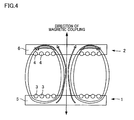
- This structure of the magnetic element 1 when compared with a structure of the same in which the magnetic part 5 is not arranged in parallel to the planar coil 3, reduces magnetic field around the planar coil 3 which is ineffective for magnetic coupling, and restrains spreading of the magnetic field shown overall, as shown in FIG. 4 .
- the magnetic element 1 raises the magnetic flux density directed to the magnetic element 2 at the power receiving end. This enables feeding power from the magnetic element 1 to the magnetic element 2, with high power transmission efficiency.
- the magnetic field generated by the alternating current flowing in the planar coil 3 generates an induced current by interplaying with another planar coil 3 arranged in parallel, and this induced current serves as a resistance.
- This phenomenon is restrained by the magnetic part 5 provided in the intervals B between windings of the planar coil 3. This reduces the resistance caused by the high magnetic flux density and the induced current, thus enabling feeding power and receiving power with high power transmission efficiency.
- the heat of the planar coil 3 is efficiently transferred to the magnetic part 5 through the wall surface 3a integrally bonded with the magnetic part 5. Therefore, the heat of the planar coil 3 is efficiently radiated through the magnetic part 5 between windings of the copper wire of the planar coil 3.
- the magnetic element 1 structured as described above has the magnetic part 5 integrally bonded with and firmly attached to the wall surface 3a of the planar coil 3 in such a manner as to fill up the intervals B between windings of the copper wire of the planar coil 3.
- This maintains the initial positional relation between the planar coil 3 and the magnetic part 5, even when the planar coil 3 and the magnetic part 5 are subject to an external force such as vibration and an impact. Therefore, the high power transmission efficiency at the initial state is maintained for a long period of time. Further, when the planar coil 3 generates heat, the heat of the planar coil 3 is efficiently transferred to the magnetic part 5 through the wall surface 3a of the planar coil 3 which is integrally bonded with the magnetic part 5.
- the heat of the planar coil 3 is efficiently radiated through the magnetic part 5.
- This enables an increased amount of power conducted, as compared with a case where the planar coil 3 and the magnetic part 5 are apart from each other.
- the amount of transmission is increased while excessive heating of the planar coil 3 is prevented, with a structure in which the planar coil 3 and the magnetic part 5 are simply integrate with each other at the wall surface 3a of the planar coil 3.
- integration of the planar coil 3 with the magnetic part 5 makes handling easier. Therefore, the work of embedding the magnetic element 1 into various devices and work for storing the same are made easier.
- the magnetic part 5 whose structure includes the resin is flexible to the external force. As such, combining the planar coil 3 with the magnetic part 5 requires relatively small external force, which makes the manufacturing process of the magnetic element 1 easy.
- thermosetting resin is used for the magnetic part 5
- a bonded state of the planar coil 3 and the magnetic part 5 is fixed simply by adding a heating process for curing the thermosetting resin to the manufacturing process of the magnetic element 1, which easily realizes a simple manufacturing process.
- a manufacturing method of the magnetic element 1 is the same as the above manufacturing method.
- a container 20 containing methyl ethyl ketone (MEK) an epoxy resin, an acrylic rubber, a phenol resin, a curing accelerator, a dispersant, a silane coupling agent are dissolved (liquefied) at a compounding ratio of 55 wt. part, 10 wt. part, 35 wt. part, 1 wt. part, 1 wt. part, and 1 wt. part, respectively.
- the epoxy resin 10 contains all of these materials dissolved in the container 20.
- the present embodiment adopts, as the organic solvent, methyl ethyl ketone which is a ketone based solvent, for the sake of solubility.
- FINEMET ® 11 as the iron-based amorphous particles is added at a compounding ratio of 700 wt. part, and mixed by using a disperser, thereby dispersing the FINEMET ® in the epoxy resin 10 (magnetic particles dispersing process).
- the liquefied epoxy resin 10 in which FINEMET ® 11 has been dispersed is applied to form a layer of approximately 300 ⁇ m in thickness, by using an applicator 25.
- the thickness of the liquefied epoxy resin 10 applied is not particularly limited; however, in terms of film formability, the thickness is usually set within a range of 30 to 500 um, preferably 50 to 300 um.
- the PET 24 may also be a plastic base material such as polyester, polyamide, polyphenylene sulfide, polyimide, and polyethylene naphthalate; a porous base material; a paper base material such as glassine paper, fine quality paper, and Japanese paper; a non-woven fabric such as cellulose, polyamide, polyester, and aramid; and a metal film base material such as copper foil, aluminum foil, SUS foil, and a nickel foil.
- a plastic base material such as polyester, polyamide, polyphenylene sulfide, polyimide, and polyethylene naphthalate
- a porous base material such as glassine paper, fine quality paper, and Japanese paper
- a non-woven fabric such as cellulose, polyamide, polyester, and aramid
- a metal film base material such as copper foil, aluminum foil, SUS foil, and a nickel foil.
- the epoxy resin 10 applied to the surface of the PET 24 is turned into the B-stage by using a thermal dryer to dry the resin for 12 minutes at 110°C (B-staging process).
- B-staging process the epoxy resin 10 in the B-stage, with a thickness of 250 ⁇ m is obtained on the surface of the PET 24.
- the temperature and the period is adjusted according to the difference in the type of resins and the thickness of the resin applied in the B-staging process.
- a plurality of epoxy resin 10 layers, in the B-stage are laminated to achieve a desirable thickness.
- two layers of epoxy resin 10 in the B-stage are laminated to achieve a thickness of 500 ⁇ m.
- another layer of epoxy resin 10 in the B-stage is placed on the epoxy resin 10 in the B-stage on the surface of the PET 24.
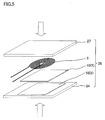
- the planar coil 3 is placed on a stack of epoxy resin 10 in the B-stage. Further, on the planar coil 3 is overlapped a plate of silicon-treated PET 27.
- planar coil 3 (conductive formed member) is formed by winding a round type copper wire material (with an insulation film) of 500 ⁇ m ⁇ in wire diameter 19 times in a spiral shape, at intervals B of 500 ⁇ m between windings of the copper wire, so as to form a planar coil having a coil inner-diameter of 5 mm ⁇ and a coil outer-diameter of 43 mm ⁇ , as hereinabove mentioned.
- a plate 28 having from the bottom a layer of the PET 24, the laminated layers of B-stage epoxy resin 10, planar coil 3, and another layer of PET 27 is pressurized from the top and bottom (pressuring process).
- the pressure vacuum laminator V-130 produced by Nichigo-Morton Co., Ltd
- the plate 28 is pressured for a pressuring period of 90 seconds at a temperature of 110°C, and a pressure of 0.1 MPa. Note that in the pressuring process too, the pressuring force, pressuring period, and the pressuring temperature are adjusted according to the type of resins used and the differences in the thicknesses of the resin layers.
- This magnetic element 1 is subjected to a post curing process (after curing process) at 150°C, for approximately one hour, so as to thermally cure the epoxy resin 10 in the B-stage (curing process). Note that, the temperature and the period are adjusted according to the type of resins used, and the differences in the thicknesses of the resin layers.
- This magnetic element 1 has a flat plate shape, with the planar coils 3 are partially exposed and buried in the sheet of magnetic part 5, as shown in FIG. 1 , and has the surface 5a and the back surface 5b to serve as the magnetism open surface facing the device on the power receiving end or the power feeding end.
- the FINEMET ® 11 which is the iron-based amorphous particles serving as the magnetic particles are dissolved in the dissolved epoxy resin 10. It is therefore easy to evenly disperse the FINEMET ® 11 in the epoxy resin 10.
- the magnetic element 1 manufactured this way facilitates achievement of even thermal conductivity and magnetism of the magnetic part 5.
- the planar coil 3 and the epoxy resin 10 in the B-stage when stacked and pressured, are easily brought into firmly attached and bonded state. That is, when the planar coil 3 having the intervals B between the adjacent windings of the copper wire and the epoxy resin 10 in the B-stage are stacked to each other and pressure, the epoxy resin 10 in the B-stage gets into the intervals B, and the epoxy resin 10 in the B-stage is closely attached and bonded with the wall surface 3a of the planar coil 3 which faces the intervals B, thus enabling integration of the epoxy resin 10 with the planar coil 3.
- the epoxy resin 10 which is a thermosetting resin is adopted for the resin, and the epoxy resin 10 in the B-stage in the curing process is subjected to the post curing process (thermal treatment) so as to bring the resin into cured state (C-stage).
- Subjecting the epoxy resin 10 in the B-stage to the post curing process (thermal treatment) cures the epoxy resin 10 in the B-stage between the intervals B of the windings of the copper wire of the planar coil 3, thus fixing the bonded state of the planar coil 3 and the epoxy resin 10.
- the magnetic element 1 manufactured has the planar coil 3 integrated with and fixed to the epoxy resin 10 containing the FINEMET ® 11.
- the structure and a manufacturing method of the magnetic element 1 are described hereinabove.
- the following describes a comparative experiment for the insertion loss (S21) in an S parameter and the power transmission efficiency of the magnetic element 1, and a comparative experiment for the heat dissipation performance.
- Example 1 the insertion loss (S21) in the S parameter and the power transmission efficiency of magnetic elements 1 and 2 each having the above magnetic part 5 are measured.
- Comparative Example 1 the insertion loss (S21) in the S parameter and the power transmission efficiency of a magnetic elements each having only the planar coil 3 but no magnetic part 5 are measured.
- Example 1 The above described magnetic elements 1 and 2 were used in Example 1. As shown in FIG. 6 , the magnetic element 1 on the power feeding end and the magnetic element 2 on the power receiving end were disposed to face each other. At this time, the magnetic element 1 and the magnetic element 2 were spaced from each other by a distance of 3 mm. The elements were further disposed so that the shaft center of the planar coil 3 and that of the planar coil 4 coincided with each other. After this, a wire bonded with the one end portion on the outer circumference side and a wire bonded with the other end portion on the inner circumference side of the planar coil 3 were connected to terminals 41 of a network analyzer 40(Agilent Technologies, Inc.).
- a wire bonded with the one end portion on the outer circumference side and a wire bonded with the other end portion on the inner circumference side of the planar coil 4 were connected to a terminal 42 of the network analyzer 40 (Agilent Technologies, Inc.). Then, an insertion loss (S21) in the S parameter and the power transmission efficiency were measured at measurement frequencies of 300 kHz, 500 kHz, and 1000 kHz.
- the power transmission efficiency is a ratio of power output from the magnetic element 2 on the power receiving end for the power supplied to the magnetic element 1 on the power feeding end.
- the power transmission efficiency is an efficiency of transferring energy from the magnetic element 1 to the magnetic element 2.
- the insertion loss "S21” means, when signals is input to the terminal 41, the signals passing through the terminal 42.
- the insertion loss "S21” is expressed in decibel and the greater the value, the higher the power transmission efficiency. In other words, the higher the insertion loss "S21", the higher the power transmission efficiency.
- the Comparative Example 1 involved a magnetic element for wireless power transmission (hereinafter, simply referred to as magnetic element), for feeding power which has only the planar coil 3 but no magnetic part 5, and a magnetic element for wireless power transmission (hereinafter, simply referred to as magnetic element), for receiving power which has only the planar coil 4 but no magnetic part 6.
- the magnetic elements were disposed so that the planar coil 3 on the power feeding end and that planar coil 4 on the power receiving end faced each other.
- the distance between the planar coil 3 and the planar coil 4 was 3 mm.
- the elements were disposed so that the shaft center of the planar coil 3 and that of the planar coil 4 coincided with each other.
- a wire bonded with the one end portion on the outer circumference side and a wire bonded with the other end portion on the inner circumference side of the planar coil 3 were connected to the terminal 41 of the network analyzer 40 (Agilent Technologies, Inc.). Further, a wire bonded with the one end portion on the outer circumference side and a wire bonded with the other end portion on the inner circumference side of the planar coil 4 were connected to the terminal 42 of the network analyzer 40 (Agilent Technologies, Inc.). Then, the insertion loss (S21) in the S parameter and the power transmission efficiency were measured at measured frequencies of 300kHz, 500kHz, and 1000kHz.
- FIG. 7A The resulting insertion losses (S21) in the S parameter of the above measurements are shown in FIG. 7A .
- the horizontal axis indicates the measured frequency and the vertical axis indicates the insertion loss "S21".
- the resulting power transmission efficiency from the above measurements are shown in FIG. 7B .
- the horizontal axis indicates the measured frequency
- the vertical axis indicates the power transmission efficiency (%).
- Example 1 resulted in a higher insertion loss (S21) in the S parameter and a higher power transmission efficiency, than Comparative Example 1, Example 1 involving magnetic element 1 for feeding power and the magnetic element 2 for receiving power having the magnetic part 5 and the magnetic part 6, respectively, Comparative Example 1 involving the magnetic element for feeding power having only the planar coil 3 but no magnetic part 5 and a magnetic element for receiving power having only the planar coil 4 but no magnetic part 6.
- the power transmission efficiency i.e., the efficiency of power transmission from the magnetic element 1 to the magnetic element 2 is improved by providing the magnetic part 5 and 6 to the magnetic element 1 and 2, respectively.
- Example 3 the temperature of the surface 5a of the magnetic element 1 having the magnetic part 5 was measured. Further, in Comparative Example 2, the surface temperature of a magnetic element having only the planar coil 3 and no magnetic part 5 was measured. Further, in Comparative Example 3, the surface temperature of a magnetic element having only a tightly-wound planar coil 59 and having no magnetic part was measured. Further, in Comparative Example 4, the surface temperature of a magnetic element 58 for wireless power transmission (hereinafter, simply referred to as magnetic element 58) having a tightly-wound planar coil 59 with a magnetic part 57 was measured.
- magnetic element 58 for wireless power transmission
- Example 3 involves the above-described magnetic element 1.
- the magnetic element 1 was disposed on four supports 50 so that the back surface 5b faces downwards.
- a wire bonded with one end portion on the outer circumference side and another wire bonded with the other end portion on the inner circumference side of the planar coil 3 of the magnetic element 1 are connected to a direct current power source 52 via a power circuit 51.
- an infrared thermography camera 54 was disposed above the magnetic element 1 so as to face its surface 5a.
- the infrared thermography camera 54 is connected to a personal computer 55, and enables observation of the surface temperature of the magnetic element 1 through its monitor.
- 2.5W-power from the direct current power source 52 was converted to an alternate current of 200 kHz by the power circuit 51, and transmitted to the magnetic element 1. Then, the surface temperature of the magnetic element 1, five minutes after the beginning of the power transmission was monitored on a personal computer 55. The surface temperature of the magnetic element 1 was measured five minutes after the beginning of the power transmission, because the surface temperature of the magnetic element 1 stabilized five minutes after the beginning of the power transmission.
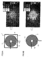
- the measurement was conducted in a portion T1 of the magnetic element 1 nearby the outer edge (hereinafter, outer edge portion T1), a portion T2 of the magnetic element 1 nearby the center portion (hereinafter, center portion T2), and a portion T3 between the outer edge and the center portion of the magnetic element 1 (hereinafter, midway portion T3), as shown in FIG. 9A .
- Comparative Example 2 involves a magnetic element for wireless power transmission (hereinafter, simply referred to as magnetic element), having a planar coil 3 but no magnetic part 5.
- the planar coil 3 is disposed on four supports 50.
- a wire bonded with one end portion on the outer circumference side and a wire bonded with the other end portion on the inner circumference side of the planar coil 3 are connected to a direct current power source 52 via the power circuit 51.
- the infrared thermography camera 54 was disposed above the planar coil 3 so as to face its surface.
- the infrared thermography camera 54 is connected to a personal computer 55, and enables observation of the surface temperature of the planar coil 3 through its monitor.
- Comparative Example 3 involves a magnetic element for wireless power transmission (hereinafter, simply referred to as magnetic element), having a tightly-wound planar coil 59 but no magnetic part.
- the tightly-wound planar coil 59 is formed by winding a round type copper wire material (with an insulation film) of 500 ⁇ m ⁇ in wire diameter 36 times in a spiral shape without intervals between windings of the copper wire, so as to form a planar coil having a coil inner-diameter of 5 mm ⁇ and a coil outer-diameter of 43 mm ⁇ .
- the planar coil 59 is disposed on four supports 50.
- a wire bonded with one end portion on the outer circumference side and a wire bonded with the other end portion on the inner circumference side of the planar coil 59 are connected to a direct current power source 52 via the power circuit 51.
- the infrared thermography camera 54 was disposed above the planar coil 59 so as to face its surface.
- the infrared thermography camera 54 is connected to a personal computer 55, and enables observation of the surface temperature of the planar coil 59 through its monitor.
- 2.5W-power from the direct current power source 52 was converted to an alternate current of 200 kHz by the power circuit 51, and transmitted to the planar coil 59.
- the surface temperature of the planar coil 59, five minutes after the beginning of the power transmission was monitored on a personal computer 55.
- Comparative Example 4 involves a magnetic element 58 for wireless power transmission (hereinafter, simply referred to as magnetic element 58), having a tightly-wound planar coil 59 but no magnetic part 57.
- the magnetic part 57 is formed in the form of square sheet of 600 ⁇ m in thickness, with the length of each side being 50 mm.
- the planar coil 59 closely attached and bonded with to the magnetic part 57 is entirely buried in the magnetic part 57.
- the magnetic element 58 of Comparative Example 4 unlike Example 3, has no intervals between windings of the copper wire of the planar coil 59; the windings of copper wire of the planar coil 59 and the magnetic part 57 are not arranged in parallel and not alternated in a direction perpendicular to the magnetic coupling direction in a vertical cross section taken in the magnetic coupling direction.
- the magnetic element 58 is disposed on four supports 50 so that the surface on which planar coil 59 can be seen is faced upward. Then, a wire bonded with one end portion on the outer circumference side and another wire bonded with the other end portion on the inner circumference side of the planar coil 59 of the magnetic element 58 are connected to a direct current power source 52 via a power circuit 51. Then, an infrared thermography camera 54 was disposed above the magnetic element 58 so as to face its surface. The infrared thermography camera 54 is connected to a personal computer 55, and enables observation of the surface temperature of the magnetic element 58 through its monitor.
- FIG. 9A shows the surface temperature of the magnetic element 1 related to Example 3.
- FIG. 9B shows the surface temperature of the planar coil 3 related to Comparative Example 2.
- FIG. 10C shows the surface temperature of the planar coil 59 related to Comparative Example 3.
- FIG. 10D shows the surface temperature of the magnetic element 58 related to Comparative Example 3.
- the resulting surface temperatures of the outer edge portion T1, the pcenter portion T2, the midway portion T3 of the magnetic element 1 related to Example 3 were 45.2°C, 52.2°C, and 54.7°C, respectively. Further, the resulting surface temperatures of the outer edge portion T1, the pcenter portion T2, and the midway portion T3 of the planar coil 3 related to Comparative Example 2 were 41.6°C, 58.8°C, and 64.9°C, respectively. Further, the resulting surface temperatures of the outer edge portion T1, the pcenter portion T2, and the midway portion T3 of planar coil 59 related to Comparative Example 3 were 40.7°C, 46.3°C, and 65.1°C, respectively. Further, the resulting surface temperatures of the outer edge portion T1, the pcenter portion T2, and the midway portion T3 of the magnetic element 58 related to Comparative Example 4 were 38.9°C, 58.5°C, and 60.4°C, respectively.
- the magnetic element 58 of Comparative Example 4 having the magnetic part 57 has a higher heat dissipation performance as compared with the magnetic element of Comparative Example 3 having only the planar coil 59 and no magnetic part 57.
- the magnetic part 57 it is possible to achieve a high heat dissipation performance, even in cases of a tightly-wound planar coil 59 having no intervals between windings of the copper wire forming the coil.
- the resulting surface temperatures in the outer edge portion T1 and the midway portion T3 are substantially the same in the tightly-wound planar coil 59 of Comparative Example 3 and the planar coil 3 of Comparative Example 2.
- the surface temperatures in the portions T2 nearby the center portion of the planar coil 59 and the planar coil 3 are significantly different; however, it is believed that the surface temperature in the portion T2 of Comparative Example 3 resulted in a significantly low temperature (46.3°C), because, in Comparative Example 3, the temperature of the atmosphere was measured at the center portion of the planar coil 59 in which portion there is not coil. Therefore, the surface temperature of the planar coil 3 related to Comparative Example 2 and the surface temperature of the tightly-wound planar coil 59 of Comparative Example 3 have substantially no difference.
- the magnetic element 1 related to Example 3 which is the planar coil 3 of Comparative Example 2 provided with the magnetic part 5 and the magnetic element 58 of Comparative Example 4 which is the tightly-wound planar coil 59 of Comparative Example 3 provided with the magnetic part 57 are compared. That is, the difference between Example 3 and Comparative Example 4 is the presence or absence of intervals between windings of the copper wire of the planar coil.
- the magnetic element 1 of Example 3 adopting the planar coil 3 having intervals between windings of the copper wire forming the coil exhibited a better heat dissipation performance, as compared with the magnetic element 58 of Comparative Example 4 adopting the planar coil 59 having no intervals between windings of the copper wire forming the coil. That is, in a magnetic element for wireless power transmission, having the magnetic part, the heat dissipation performance is improved with intervals between windings of the copper wire forming the planar coil.
- the magnetic elements 1 of the above Examples each is formed in a flat plate shape and has the magnetic part 5 in the form of sheet having the surface 5a on which a part of the planar coil 3 exposed and a planar back surface 5b.
- FIG. 11A,B it is possible to provide a metal made heat sink 101 on the back surface 5b of the magnetic element 1.
- This heat sink 101 has a plane surface which contacts the back surface 5b of the magnetic element 1; however, its surface 101a on the opposite side to the contact surface has a plurality of grooves 115.
- FIG. 11A is a perspective view showing the surface 5a of the magnetic element having the heat sink 101.
- FIG. 11B is a perspective view showing the grooves 115 of the heat sink 101 on the magnetic element 1.
- the surficial area is increased thereby improving the heat dissipation performance.
- the heat is transferred from the back surface 5b of the magnetic element 1 to the heat sink 101, and efficiently dissipated through the grooves 115.
- FIG. 12A,B it is possible to form a plurality of grooves 215 on the back surface 205b of the magnetic part 205 of the magnetic element 201.
- FIG. 12A is a perspective view showing the surface 205a of the magnetic element 201.
- FIG. 12B is a perspective view showing the back surface 205b of the magnetic element 201.
- a die having a groove forming unit for forming a plurality of grooves is placed on the back surface (the surface to become the back surface 205b of the magnetic part 205) of the epoxy resin in the B-stage, during the pressuring process. Then, a plate sequentially including, from the bottom, the die, the epoxy resin in the B-stage, and the planar coil is pressured from the top and bottom to form the grooves 215.
- the grooves 215 are formed on the back surface 205b of the magnetic part 205 of the magnetic element 201. Formation of these grooves 215 increases the surficial area of the magnetic part 205, which consequently achieves a higher heat dissipation performance.
- the structures of the grooves are not limited to the ones shown in FIG. 12 .
- the magnetic part 5 is not limited to a thermosetting resin, and a thermoplastic resin may be also adoptable.
- a thermoplastic resin can be repetitively softened by heating and made solid by cooling. Specifically, a thermoplastic resin softens and can be formed into any intended shape by heating it up to its melting point. Therefore, a thermoplastic resin can be injected between windings of the copper wire of the planar coil 3.
- the thermoplastic resin includes: PP(polypropylene), ABS(Acrylonitrile butadiene styrene copolymer), PET(polyethylene terephthalate), PE (polyethylene), PC (polycarbonate).
- thermoplastic resin softened by a thermal treatment is fixed by supplying it to the intervals B between windings of the copper wire of the planar coil 3, and then solidifying the resin by cooling.
- connection state of the planar coil 3 and the thermoplastic resin serving as the magnetic part is fixed simply by supplying the thermoplastic resin softened by a thermal treatment in the intervals B between windings of the copper wire of the planar coil 3, and then solidifying the resin by cooling.
Landscapes
- Engineering & Computer Science (AREA)
- Power Engineering (AREA)
- Manufacturing & Machinery (AREA)
- Physics & Mathematics (AREA)
- Electromagnetism (AREA)
- Chemical & Material Sciences (AREA)
- Dispersion Chemistry (AREA)
- Coils Of Transformers For General Uses (AREA)
- Soft Magnetic Materials (AREA)
- Coils Or Transformers For Communication (AREA)
- Charge And Discharge Circuits For Batteries Or The Like (AREA)
- Manufacturing Cores, Coils, And Magnets (AREA)
Abstract
Description
- The present invention relates to magnetic elements for wireless power transmission, which enables contactless power transmission.
- There have been an increasing number of machines activated by cordless power supply utilizing electromagnetic inductance, such as electric toothbrushes, cordless telephones, and portable devices (e.g., PTL 1). There have also been developments of machines activated by cordless power supply utilizing magnetic resonance, in relation to wall-hang television sets and personal computers (e.g., PTL 2). To add this, there have been many developments and suggestions for magnetic elements for wireless power transmission capable of feeding high power with high power transmission efficiency, in the field of wireless power transmission.
- However, feeding high power with high power transmission efficiency in such a magnetic element for wireless power transmission causes an excessive heat generation. This generated heat in the magnetic element for wireless power transmission may cause a problem to the magnetic element itself or to the functional parts of the element.
- To address this problem of heat generation, for example, one approach is to adopt a structure of substrate having an in-built coil such as the one disclosed in
PTL 3, in which a planar coil conductor to serve as the heat source is covered with a magnetic layer so as to radiate the heat outside through a conductor layer for heat transfer which is provided to the magnetic layer. This, without a doubt, enables radiation of heat generated by the planar coil to the outside. -
- [PTL 1] Japanese Unexamined Patent Publication No.
47700/2004 Tokukai 2004-47700 - [PTL 2] Japanese Unexamined Patent Publication No.
239848/2010 Tokukai 2010-239848 - [PTL 3] Japanese Unexamined Patent Publication No.
205264/2008 Tokukai 2008-205264 - However, since the planar coil itself is covered by the magnetic layer, the magnetic field is shielded. This structure therefore is not suitable for use in a magnetic element for wireless power transmission, which utilizes electromagnetic inductance or magnetic resonance. Further, the structure necessitates an extra work in the manufacturing process, because the planar coil and the conductor layer for heat transfer need to be built in the magnetic layer.
- In view of the above problems, an obj ect of the present invention is to provide a magnetic element for wireless power transmission, which has improved heat dissipation performance and which is capable of feeding power with high power transmission efficiency, and to provide a method of manufacturing such an element.
- An aspect of the present invention to achieve the above object is a magnetic elements for wireless power transmission (hereinafter, simply referred to as magnetic element), which generates an induced electromotive force, including: a conductor portion through which an alternating current flows; and a magnetic part arranged in parallel to the conductor portion, wherein the magnetic part includes a resin in which magnetic particles are dispersed, and the conductor portion is at least partially bonded and integrated with the magnetic part, while being electrically insulated therefrom, by the resin.
- In the above structure in which the conductor portion and the magnetic part are at least partially bonded and integrated with each other, the positional relation between the conductor portion and the magnetic part is maintained at the initial state, even when the conductor portion and the magnetic part are subject to an external force such as vibration or an impact. Thus, high power transmission efficiency at the initial stage is maintained for a long period of time. Further, when the conductor portion generates heat, the heat of the conductor portion is efficiently transferred to the magnetic part through the integrally bonded portions. It is therefore possible to efficiently radiate the heat of the conductor portion through the magnetic part. Thus, the amount of power conducted is increased as compared with a case where the conducting portion and the magnetic part are apart from each other. As the result, excessive heating of the conducting portion is prevented while improving the amount of power transmitted, with a simple structure in which the conducting portion and the magnetic part are at least partially integrated. The integration of the conducting portion with the magnetic part makes handling of the magnetic element easier. Therefore, the work for building the element into various devices and maintenance of the same becomes easy, and manufacturing of the magnetic element is simplified.
- In the magnetic element of the above aspect of the present invention to achieve the object, the resin is a thermosetting resin.
- In the structure, a bonded state of the conductive portion and the magnetic part is fixed simply by adding a thermal treatment for curing the thermosetting resin to the manufacturing process of the magnetic element, which easily realizes a simple manufacturing process.
- In the magnetic element of the above aspect of the present invention to achieve the object, the resin is a thermoplastic resin.
- With the structure, the bonded state of the conductor portion and the magnetic part is fixed by supplying the softened thermoplastic resin between the conductor portion and another conductor portion and solidifying the resin by cooling. As such, the manufacturing process of the magnetic elements for wireless power transmission is easily made easier simply by adding a thermal treatment for softening the thermoplastic resin to the manufacturing process.
- In the magnetic element of the above aspect of the present invention to achieve the object, the magnetic particles are soft magnetism particles.
- In the magnetic element of the above aspect of the present invention to achieve the object, the soft magnetism particles are metal based magnetic particles.
- Since the metal based magnetic particles exhibit a high magnetic permeability, the above structure maintains a high magnetic shielding rate of the magnetic part.
- In the magnetic element of the above aspect of the present invention to achieve the object, the metal based magnetic particles are amorphous particles.
- These iron-based amorphous particles in the above structure have no crystal structure and have a high magnetic permeability. Therefore, it is possible to reduce the thickness of the magnetic part, while maintaining a high magnetic shielding rate.
- In the magnetic element of the above aspect of the present invention to achieve the object, the magnetic part has a plurality of grooves.
- With the structure in which a plurality of grooves are formed on the magnetic part, the surficial area of the magnetic part is increase. This improves the heat dissipation performance.
- Another aspect of the present invention to achieve the above object is a method of manufacturing a magnetic element for wireless power transmission including: a magnetic particles dispersing process for dispersing magnetic particles in a resin; a B-staging process for heating the resin in which the magnetic particles are dispersed so as to cause the resin in a B-stage; a pressuring process for applying a pressure to a stack of conductor portions and the resin in the B-stage; and a curing process for curing the resin in the B-stage which is bonded with the conductor portions.
- In the above method, the magnetic particles are dispersed in the resin. Therefore, the magnetic particles are easily evenly scattered in the resin. The magnetic element manufactured this way facilitates achievement of even thermal conductivity and magnetic property of the magnetic part.
Further, since the resin is brought into the B-stage by heating, the conductor portions and the resin in the B-stage are closely attached and bonded with each other by applying a pressure to a stack of the conductor portions and the resin in the B-stage stacked. In other words, the conductor portions and the resin in the B-stage are bonded and integrated with each other. By curing the resin in the B-stage which is bonded with the conductor portions, the resulting magnetic elements for wireless power transmission has conductor portions integrated with and fixed to a resin containing magnetic particles. - The method of the other aspect of the present invention to achieve the object is adapted so that, in the pressuring process, a plurality of grooves are formed to the resin in the B-stage.
- The above method forming a plurality of grooves on the resin increases the surficial area of the resin in which the magnetic particles are dispersed. This improves the heat dissipation performance.
- The method of the other aspect of the present invention to achieve the object is adapted so that, in the pressuring process, a conductive formed member having an interval between its conductor portions adjacent to each other is stacked with the resin in the B-stage, and is bonded by applying a pressure.
- In the above method, when a pressure is applied to a stack of the resin in the B-stage and the conductive formed member having intervals between its conductor portions adjacent to each other, the resin in the B-stage enters the intervals, and is closely attached and bonded with the wall surface of the conductor portions facing the intervals.
- The method of the other aspect of the present invention to achieve the object is adapted so that the resin is a thermosetting resin, and in the curing process, the thermosetting resin in the B-stage is cured by a thermal treatment.
- With the above method, the connection state of the conductor portions and the resin is fixed simply by conducting a thermal treatment for curing the thermosetting resin.
- The method of the other aspect of the present invention to achieve the object is adapted so that the resin is a thermoplastic resin, and in the curing process, the thermoplastic resin softened by a thermal treatment is supplied between the conductor portions and is fixed by solidifying the resin by cooling.
- With the above method, the connection state between the conductor portions and the magnetic part is fixed simply by supplying the thermoplastic resin softened by the thermal treatment, between the conductor portions, and solidifying the resin by cooling. Therefore, it is easily possible to simplify the process of solidifying the resin.
- There is provided a magnetic element for wireless power transmission, which has a high heat dissipation performance and which is capable of feeding power with high power transmission efficiency, and a method of manufacturing such an element.
-
- [
FIG. 1] FIG. 1 is a diagram showing a structure of a magnetic element for wireless power transmission, related to Example. - [
FIG. 2] FIG. 2 is a cross sectional view of a magnetic element for wireless power transmission, which is taken along the line A-A'. - [
FIG. 3] FIG. 3 is a first explanatory diagram showing the state of magnetic field of the magnetic element for wireless power transmission. - [
FIG. 4] FIG. 4 is a second explanatory diagram showing the state of magnetic field of the magnetic element for wireless power transmission. - [
FIG. 5] FIG. 5 is an explanatory diagram for explaining a method of manufacturing the magnetic element for wireless power transmission. - [
FIG. 6] FIG. 6 is an explanatory diagram showing a structure for measuring an insertion loss (S21) of an S parameter and a power transmission efficiency of the magnetic element for wireless power transmission. - [
FIG. 7] FIG. 7A is a graph showing an insertion loss (S21) of an S parameter of the magnetic element for wireless power transmission.FIG. 7B is a graph showing a power transmission efficiency of the magnetic element for wireless power transmission. - [
FIG. 8 ] is an explanatory diagram of a structure for measuring a surface temperature of the magnetic element for wireless power transmission. - [
FIG. 9] FIG. 9A is a diagram showing a measurement result of the surface temperature of a magnetic element for wireless power transmission related to Example 3.FIG. 9B is a diagram showing a measurement result of the surface temperature of a planar coil related to Comparative Example 2. - [
FIG. 10] FIG. 10C is a diagram showing a measurement result of the surface temperature of a planar coil related to Comparative Example 3.FIG. 10D is a diagram showing a measurement result of the surface temperature of a magnetic element for wireless power transmission related to Comparative Example 4. - [
FIG. 11] FIG. 11A is a perspective view showing a surface of a magnetic element for wireless power transmission, having a heat sink.FIG. 11B is a perspective view showing a groove of the heat sink of the magnetic element for wireless power transmission, having the heat sink. - [
FIG. 12] FIG. 12A is a perspective view showing a surface of a magnetic element for wireless power transmission related to another embodiment.FIG. 12B is a perspective view showing the back surface of the magnetic element for wireless power transmission related to the other embodiment. - [
FIG. 13] FIG. 13A is a perspective view of the magnetic element for wireless power transmission related to the other embodiment. -
FIG. 13B is a perspective view showing the magnetic element for wireless power transmission related to the other embodiment. - First, the following describes
magnetic elements - As shown in
FIG. 1 , themagnetic elements magnetic elements 1 and 2) are structured to generate an induced electromotive force by magnetic coupling, and are each usable for both feeding power and receiving power. For feeding power, for example, themagnetic element 1 is applicable to a power supply device for feeding power to a device placed on somewhere while being used such as a personal computer and a mouse, which device is activated by cordless power feeding using electromagnetic inductance. Further, themagnetic element 1 is also applicable to a power supply device or the like for feeding power to an electric vehicle, and a wall-hanging type device such as a wall-hanging type flat panel television, which device is activated by cordless power feeding using magnetic resonance. - On the other hand, for receiving power, the
magnetic element 2 is applicable to a device such as a personal computer and a mouse, which are placed or brought into contact with a power supply device, or to a wall-hanging type device such as a wall-hanging type flat panel television, or an electric vehicle. - As shown in
FIG. 1 , themagnetic element 1 for feeding power includes: a planar coil 3 (conductor portion) through which an alternating current flows; and amagnetic part 5 arranged in parallel to theplanar coil 3 as shown in the cross sectional view taken along the line A-A' ofFIG. 1 . Themagnetic part 5 has resin in which magnetic particles are dispersed, which is at least partially bonded and integrated with the conductor portion while being electrically insulated. Note that themagnetic element 2 for receiving power has the similar structure. - Examples of the
conductor portion 3 in which the alternating current flows include a spiral type coil or a solenoid type coil. By themagnetic part 5 being arranged in parallel to theconductor portion 3, it means that themagnetic part 5 is arranged adjacent to theconductor portion 3, in a cross section taken in the a direction of magnetic coupling between themagnetic element 1 for feeding power and themagnetic element 2 for receiving power. The direction of magnetic coupling is a direction in which the center of a magnetically coupling side and the center of a magnetically coupled side, when the magnetically coupling side (power feeding end) and the magnetically coupled side (power receiving end) are disposed to face each other and in a positional relation such that the magnetic coupling becomes the strongest, thus generating a maximum induced electromotive force, as in a case where themagnetic element 1 for feeding power and themagnetic element 2 for receiving power having the same size are disposed so their center portions face each other. - In the above structure in which the
planar coil 3 and themagnetic part 5 are at least partially bonded and integrated with each other, the positional relation between theplanar coil 3 and themagnetic part 5 is maintained at the initial state, even when theplanar coil 3 and themagnetic part 5 are subject to an external force such as vibration or an impact. Thus, high power transmission efficiency at the initial stage is maintained for a long period of time. Further, when theplanar coil 3 generates heat, the heat of theplanar coil 3 is efficiently transferred to themagnetic part 5 through the integrally bonded portions. It is therefore possible to efficiently radiate the heat of the conductor portion through themagnetic part 5. Thus, the amount of power conducted is increased as compared with a case where theplanar coil 3 and themagnetic part 5 are apart from each other. As the result, excessive heating of theplanar coil 3 is prevented while improving the amount of power transmitted, with a simple structure in which theplanar coil 3 and themagnetic part 5 are at least partially integrated. The integration of theplanar coil 3 with themagnetic part 5 makes handling of themagnetic element 1 easier. Therefore, the work for mounting theelement 1 into various devices and maintenance of the same becomes easy, and manufacturing of themagnetic element 1 is simplified. - Next, the following details how the
magnetic element magnetic element 1 to themagnetic element 2, using electromagnetic inductance. - As shown in
FIG. 1 , in themagnetic element 1 for feeding power, the planar coil 3 (conductor portion) through which an alternating current flows and themagnetic part 5 adjacent to theplanar coil 3 in a cross sectional view taken in a magnetic coupling direction, i.e., cross sectional view taken along the line A-A' ofFIG. 1 andFIG. 2 , are arranged in parallel to each other in a direction perpendicular to the magnetic coupling direction. Themagnetic part 5 is structured by a resin in which magnetic particles are dispersed, and at least a part of the resin is bonded and integrated with theplanar coil 3 while being electrically insulated. Note that themagnetic element 2 for receiving power has the similar structure, and the explanation is omitted. Note that the "direction perpendicular to" encompasses a "direction substantially perpendicular to". - The
planar coil 3 is formed by winding a round type copper wire material (with an insulation film) of 500 µm□ in wire diameter 19 times in a spiral shape, at intervals B of 500 µm between windings of the copper wire, so as to form a planar coil having a coil inner-diameter of 5 mm□ and a coil outer-diameter of 43 mm□. The material for theplanar coil 3 is not limited as long as it is a metal material such as Cu, or Al. Further, the above mentioned structure of theplanar coil 3 is no more than an example, and the shape and the size of the copper wire material, the size of each interval, and the number of windings are modifiable as needed. - Further, in the
magnetic element 1 at the power feeding end, theplanar coil 3 has one end portion on the outer circumference side and another end portion on the inner circumference side which are connected to a not-shown pair of terminals, respectively. The pair of terminals is connected to a power source device, so as to enable supplying of an alternating power of any frequency to theplanar coil 3. Similarly, theplanar coil 4 in themagnetic element 2 at the power receiving end also has one end portion on the outer circumference side and another end portion on the inner circumference side which are connected to a not-shown pair of terminals, respectively. Then, the pair of terminals are directly connected to a drive device or connected to a rectifier. In cases where the terminals are connected to the rectifier, that rectifier smoothens the alternating power generated by the electromagnetic inductance for use in charging a battery or activating a drive device. - The
magnetic part 5 is made in the form of a square sheet with each side being 50 mm, and the thickness being 600 µm. As shown inFIG. 2 , themagnetic part 5 is bonded with and closely attached to awall surface 3a of theplanar coil 3 so as to fill the intervals B of 500 µm of theplanar coil 3. This way, in the vertical cross section (A-A'cross sectional view) matching with the magnetic coupling direction, theplanar coil 3 and themagnetic part 5 are arranged in parallel to each other in a direction perpendicular to the magnetic coupling direction. Further, on thewall surface 3a of theplanar coil 3, themagnetic part 5 is bonded and integrated with theplanar coil 3, while being electrically insulated. Note that the above mentioned structure of themagnetic part 5 is no more than an example, and the shape, the size, the size of the intervals, and the like are modifiable as needed. - Further, as shown in
FIG. 1 , themagnetic element 1 has asurface 5a which serves as a magnetism open surface which faces the device on the power receiving end or the power feeding end, and aback surface 5b. A part of theplanar coil 3 is exposed on thesurface 5a of the sheet-formmagnetic part 5. - The
magnetic part 5 is structured by a resin in which magnetic particles are dispersed. This Example deals with a case of adopting anepoxy resin 10 as the resin which is a thermosetting resin. However, the resin is not particularly limited and is suitably adoptable as long as the resin is not the one that is not deteriorated even if the resin after being cured is left under a high temperature and/or a high humidity. - Examples of the epoxy resin includes: a glycidyl amine type epoxy resin, a bisphenol A type epoxy resin, a bisphenol F type epoxy resin, a phenol novolac type epoxy resin, a cresol novolac type epoxy resin, a biphenyl type epoxy resin, a naphthalin type epoxy resin, a aliphatic epoxy resin, a halogenated epoxy resin. These resins may be used singly or in combinations.
- Note that, as the thermosetting resin, the following resins are also adoptable singly or in combination instead of the epoxy resin: a phenol resin, a melamine resin, a vinylester resin, a cyano ester resin, a maleimide resin, a thermosetting acrylic resin.
- Further, a phenol resin is added to the
epoxy resin 10 as an epoxy curing agent. The phenol resin serves as a curing agent for the epoxy resin, and examples thereof includes phenol novolac, naphthol novolac, biphenyl novolac, and the like. These substances may be adopted singly or in combination. A blending ratio of theabove epoxy resin 10 and the phenol resin is preferably such that 0.5 to 2.0 eq. of hydroxy group in the phenol resin is blended with 1 eq. of epoxy group in the epoxy resin. More preferably, 0.8 to 1.2 eq. - Further, for example, an elastic body or a curing accelerator may be added to the resin structuring the
magnetic part 5. - Examples of the elastic body includes: a rubber component traditionally used in an epoxy resin based adhesive agent such as acrylonitrile-butadiene rubber (NBR) and acrylic rubber, an acrylic resin, a phenoxy resin, a polyamide resin and the like. These materials may be used singly or in combination. In terms of flexibility of the sheet, it is preferable to adopt the NBR or the acrylic rubber. Further, it is particularly preferable that at least 5 wt. %, more preferably 5 to 30 wt. %, and even more preferably 5 to 20 wt. % of any of these materials adopted is copolymerized.
- The curing accelerator used along with the
epoxy resin 10 and the phenol resin is, for example, an amine type curing accelerator, or a phosphorus type curing accelerator. Examples of the amine type curing accelerator include imidazole derivatives such as 2-imidazole, and triethanol amine, and the like. Further, examples of the phosphorus type curing accelerator include triphenylphosphine and tetraphenylphosphonium. These materials may be used singly or in combination. The amount of the curing accelerator blended is preferably set to 0.1 to 2 wt. % of the entire epoxy resin composition. Further, in terms of fluidity of the epoxy resin composition, the amount to be blended is particularly preferably 0.15 to 0.35 wt. %. - Additionally to the epoxy resin, the epoxy curing agent, the elastic body, and the curing accelerator, it is possible to add a traditionally known additive such as pigment, a silane coupling agent, a dispersant, a defoamer, a flame retardant, an ion trapping agent, and the like to the extent that the properties of the
magnetic part 5 are not deteriorated. - The resin of the
magnetic part 5 has therein magnetic particles dispersed. As the magnetic particles, soft magnetism particles are used. However, of the soft magnetism particles, it is preferable to adopt metal based magnetic particles. To add this, amorphous particles, among the metal based magnetic particles, are preferable. Note that the present embodiment deals with a case where the spherical FINEMET® (produced by Hitachi Metals, Ltd.) which is iron-based amorphous particles is used as the magnetic particles. These iron-based amorphous particles such as FINEMET® have no crystal structure and have a high magnetic permeability. Therefore, it is possible to reduce the thickness of themagnetic part 5, while maintaining a high magnetic shielding rate. - The soft magnetism particles are not particularly limited; however, examples of the soft magnetism particles include: permalloy based particles, silicon steel based particles, iron based magnetic particles and the like. Further, the iron based magnetic particles are not particularly limited, and any iron based magnetic particles may be suitably used, provided that a high magnetic permeability and a high thermal conductivity is achieved. An Fe-Al based alloy such as alperm, an Fe-Si based alloy such as silicon steel, an Fe-Al-Si based alloy such as sendust, ore a mixed particles of these may be adoptable. It is also possible to adopt particles of any one of an Fe-Ni based alloy, an Fe-Ni-Mo based alloy, an Fe-Ni-Mo-Cu based alloy, an Fe-Ni-Mo-Mn based alloy, or a mixed particles of any of these alloys each of which is a permalloy based alloy. Further, it is possible to adopt particles of any one of an Fe-Zr-B based alloy, a Fe-Zr-Nb-B based alloy, an Fe-Zr-Cu-B, an Fe-Si-B-Nb-Cu based alloy, an Fe-Co-Si-B-Nb-Cu based alloy, or a mixed particles of any of these alloys each of which is a non-crystalline material exhibiting a high magnetic permeability. Further, the amorphous particles may be particles of any one of an Fe-B-Si based alloy, an Fe-Co-Si-B based alloy, an Fe-B-Si-C based alloy, an Fe-Co-Ni-Si-B based alloy, or mixed particles of any of these alloys each of which is an amorphous alloy.
- In cases where the magnetic particles are spherical particles, the mean grain diameter is 1 µm to 300 µm, preferably 20 µm to 50 µm. The amount of such spherical magnetic particles mixed into the resin is 50 Vol% to 90 Vol%. The reasons for the above ranges of mean grain diameters of the spherical particles are as follows. Namely, too small a mean grain diameter causes significant influence of a diamagnetic field, which deteriorates the magnetic permeability, and good absorption property becomes hard to obtain. On the other hand, too great a mean grain diameter of the spherical particles in the
magnetic part 5 hinders reduction of the thickness, and deteriorates the smoothness of the surface of themagnetic part 5. - Further, in cases where the magnetic particles are flat particles, 20 to 70 vol%, preferably, 30 to 60 Vol% of flat magnetic particles with a grain diameter of not more than 50 µm, and with the aspect ratio of 10 or higher are added to the resin and mixed. The grain diameter smaller than 50 µm or the aspect ratio being less than 10 causes significant influence of a diamagnetic field, deteriorating the property of the magnetic field. Further, the amount of particles added to the resin being less than 20 vol% does not achieve an excellent magnetic property, and the amount of particles added being more than 70 vol% makes the sheet fragile.
- In the above structure, when a power source device is bonded to the
magnetic element 1, and a high frequency alternating current (alternating power) is supplied, themagnetic element 1 generates an alternate magnetic field. As shown inFIG. 3 , in themagnetic element 1, theplanar coil 3 and themagnetic part 5 are arranged in parallel to each other relative to a direction perpendicular to the magnetic coupling direction, in a cross section taken in the magnetic coupling direction. This structure of themagnetic element 1, when compared with a structure of the same in which themagnetic part 5 is not arranged in parallel to theplanar coil 3, reduces magnetic field around theplanar coil 3 which is ineffective for magnetic coupling, and restrains spreading of the magnetic field shown overall, as shown inFIG. 4 . As the result, themagnetic element 1 raises the magnetic flux density directed to themagnetic element 2 at the power receiving end. This enables feeding power from themagnetic element 1 to themagnetic element 2, with high power transmission efficiency. - Further, inside the
magnetic element 1, the magnetic field generated by the alternating current flowing in theplanar coil 3 generates an induced current by interplaying with anotherplanar coil 3 arranged in parallel, and this induced current serves as a resistance. This phenomenon is restrained by themagnetic part 5 provided in the intervals B between windings of theplanar coil 3. This reduces the resistance caused by the high magnetic flux density and the induced current, thus enabling feeding power and receiving power with high power transmission efficiency. - Further, when the
planar coil 3 generates heat, the heat of theplanar coil 3 is efficiently transferred to themagnetic part 5 through thewall surface 3a integrally bonded with themagnetic part 5. Therefore, the heat of theplanar coil 3 is efficiently radiated through themagnetic part 5 between windings of the copper wire of theplanar coil 3. - In the
magnetic element 1 structured as described above has themagnetic part 5 integrally bonded with and firmly attached to thewall surface 3a of theplanar coil 3 in such a manner as to fill up the intervals B between windings of the copper wire of theplanar coil 3. This maintains the initial positional relation between theplanar coil 3 and themagnetic part 5, even when theplanar coil 3 and themagnetic part 5 are subject to an external force such as vibration and an impact. Therefore, the high power transmission efficiency at the initial state is maintained for a long period of time. Further, when theplanar coil 3 generates heat, the heat of theplanar coil 3 is efficiently transferred to themagnetic part 5 through thewall surface 3a of theplanar coil 3 which is integrally bonded with themagnetic part 5. Therefore, the heat of theplanar coil 3 is efficiently radiated through themagnetic part 5. This enables an increased amount of power conducted, as compared with a case where theplanar coil 3 and themagnetic part 5 are apart from each other. As the result, the amount of transmission is increased while excessive heating of theplanar coil 3 is prevented, with a structure in which theplanar coil 3 and themagnetic part 5 are simply integrate with each other at thewall surface 3a of theplanar coil 3. Further, integration of theplanar coil 3 with themagnetic part 5 makes handling easier. Therefore, the work of embedding themagnetic element 1 into various devices and work for storing the same are made easier. Further, themagnetic part 5 whose structure includes the resin is flexible to the external force. As such, combining theplanar coil 3 with themagnetic part 5 requires relatively small external force, which makes the manufacturing process of themagnetic element 1 easy. - Further, since a thermosetting resin is used for the
magnetic part 5, a bonded state of theplanar coil 3 and themagnetic part 5 is fixed simply by adding a heating process for curing the thermosetting resin to the manufacturing process of themagnetic element 1, which easily realizes a simple manufacturing process. - Next, the following describes a manufacturing method of the
magnetic element 1. Note that a manufacturing method of themagnetic element 2 is the same as the above manufacturing method. - In a
container 20 containing methyl ethyl ketone (MEK), an epoxy resin, an acrylic rubber, a phenol resin, a curing accelerator, a dispersant, a silane coupling agent are dissolved (liquefied) at a compounding ratio of 55 wt. part, 10 wt. part, 35 wt. part, 1 wt. part, 1 wt. part, and 1 wt. part, respectively. Note that the following description assumes that theepoxy resin 10 contains all of these materials dissolved in thecontainer 20. The present embodiment adopts, as the organic solvent, methyl ethyl ketone which is a ketone based solvent, for the sake of solubility. - Next, in the
container 20 containing the liquefiedepoxy resin 10, FINEMET®11 as the iron-based amorphous particles is added at a compounding ratio of 700 wt. part, and mixed by using a disperser, thereby dispersing the FINEMET® in the epoxy resin 10 (magnetic particles dispersing process). - Next, on one side of a plate of
PET 24 with a silicon-treated surface, the liquefiedepoxy resin 10 in which FINEMET®11 has been dispersed is applied to form a layer of approximately 300 µm in thickness, by using anapplicator 25. The thickness of the liquefiedepoxy resin 10 applied is not particularly limited; however, in terms of film formability, the thickness is usually set within a range of 30 to 500 um, preferably 50 to 300 um. Note that thePET 24 may also be a plastic base material such as polyester, polyamide, polyphenylene sulfide, polyimide, and polyethylene naphthalate; a porous base material; a paper base material such as glassine paper, fine quality paper, and Japanese paper; a non-woven fabric such as cellulose, polyamide, polyester, and aramid; and a metal film base material such as copper foil, aluminum foil, SUS foil, and a nickel foil. - Next, the
epoxy resin 10 applied to the surface of thePET 24 is turned into the B-stage by using a thermal dryer to dry the resin for 12 minutes at 110°C (B-staging process). As the result, theepoxy resin 10 in the B-stage, with a thickness of 250 µm is obtained on the surface of thePET 24. Note that the temperature and the period is adjusted according to the difference in the type of resins and the thickness of the resin applied in the B-staging process. - Next, a plurality of
epoxy resin 10 layers, in the B-stage are laminated to achieve a desirable thickness. In the present embodiment, two layers ofepoxy resin 10 in the B-stage are laminated to achieve a thickness of 500 µm. Specifically, as shown inFIG. 5 , another layer ofepoxy resin 10 in the B-stage is placed on theepoxy resin 10 in the B-stage on the surface of thePET 24. Then, theplanar coil 3 is placed on a stack ofepoxy resin 10 in the B-stage. Further, on theplanar coil 3 is overlapped a plate of silicon-treatedPET 27. Note that the planar coil 3 (conductive formed member) is formed by winding a round type copper wire material (with an insulation film) of 500 µm□ in wire diameter 19 times in a spiral shape, at intervals B of 500 µm between windings of the copper wire, so as to form a planar coil having a coil inner-diameter of 5 mm□ and a coil outer-diameter of 43 mm□, as hereinabove mentioned. - Then, a
plate 28 having from the bottom a layer of thePET 24, the laminated layers of B-stage epoxy resin 10,planar coil 3, and another layer ofPET 27 is pressurized from the top and bottom (pressuring process). In this pressuring process, the pressure vacuum laminator (V-130 produced by Nichigo-Morton Co., Ltd) is used for vacuum drawing for 10 seconds at 3 hPa. Then, theplate 28 is pressured for a pressuring period of 90 seconds at a temperature of 110°C, and a pressure of 0.1 MPa. Note that in the pressuring process too, the pressuring force, pressuring period, and the pressuring temperature are adjusted according to the type of resins used and the differences in the thicknesses of the resin layers. - Lastly, the
magnetic element 1 taken out is subjected to a post curing process (after curing process) at 150°C, for approximately one hour, so as to thermally cure theepoxy resin 10 in the B-stage (curing process). Note that, the temperature and the period are adjusted according to the type of resins used, and the differences in the thicknesses of the resin layers. Thismagnetic element 1 has a flat plate shape, with theplanar coils 3 are partially exposed and buried in the sheet ofmagnetic part 5, as shown inFIG. 1 , and has thesurface 5a and theback surface 5b to serve as the magnetism open surface facing the device on the power receiving end or the power feeding end. - With the manufacturing method, the FINEMET® 11 which is the iron-based amorphous particles serving as the magnetic particles are dissolved in the dissolved
epoxy resin 10. It is therefore easy to evenly disperse the FINEMET®11 in theepoxy resin 10. Themagnetic element 1 manufactured this way facilitates achievement of even thermal conductivity and magnetism of themagnetic part 5. - Further, since the
epoxy resin 10 is brought into the B-stage, theplanar coil 3 and theepoxy resin 10 in the B-stage, when stacked and pressured, are easily brought into firmly attached and bonded state. That is, when theplanar coil 3 having the intervals B between the adjacent windings of the copper wire and theepoxy resin 10 in the B-stage are stacked to each other and pressure, theepoxy resin 10 in the B-stage gets into the intervals B, and theepoxy resin 10 in the B-stage is closely attached and bonded with thewall surface 3a of theplanar coil 3 which faces the intervals B, thus enabling integration of theepoxy resin 10 with theplanar coil 3. - Further, the
epoxy resin 10 which is a thermosetting resin is adopted for the resin, and theepoxy resin 10 in the B-stage in the curing process is subjected to the post curing process (thermal treatment) so as to bring the resin into cured state (C-stage). Subjecting theepoxy resin 10 in the B-stage to the post curing process (thermal treatment) cures theepoxy resin 10 in the B-stage between the intervals B of the windings of the copper wire of theplanar coil 3, thus fixing the bonded state of theplanar coil 3 and theepoxy resin 10. Then, with theepoxy resin 10 in the B-stage being cured while being bonded with theplanar coil 3, themagnetic element 1 manufactured has theplanar coil 3 integrated with and fixed to theepoxy resin 10 containing the FINEMET®11. - The structure and a manufacturing method of the
magnetic element 1 are described hereinabove. The following describes a comparative experiment for the insertion loss (S21) in an S parameter and the power transmission efficiency of themagnetic element 1, and a comparative experiment for the heat dissipation performance. - First, in Example 1, the insertion loss (S21) in the S parameter and the power transmission efficiency of
magnetic elements magnetic part 5 are measured. In Comparative Example 1, the insertion loss (S21) in the S parameter and the power transmission efficiency of a magnetic elements each having only theplanar coil 3 but nomagnetic part 5 are measured. - The above described
magnetic elements FIG. 6 , themagnetic element 1 on the power feeding end and themagnetic element 2 on the power receiving end were disposed to face each other. At this time, themagnetic element 1 and themagnetic element 2 were spaced from each other by a distance of 3 mm. The elements were further disposed so that the shaft center of theplanar coil 3 and that of theplanar coil 4 coincided with each other. After this, a wire bonded with the one end portion on the outer circumference side and a wire bonded with the other end portion on the inner circumference side of theplanar coil 3 were connected toterminals 41 of a network analyzer 40(Agilent Technologies, Inc.). Further, a wire bonded with the one end portion on the outer circumference side and a wire bonded with the other end portion on the inner circumference side of theplanar coil 4 were connected to aterminal 42 of the network analyzer 40 (Agilent Technologies, Inc.). Then, an insertion loss (S21) in the S parameter and the power transmission efficiency were measured at measurement frequencies of 300 kHz, 500 kHz, and 1000 kHz. - It should be noted that the power transmission efficiency is a ratio of power output from the
magnetic element 2 on the power receiving end for the power supplied to themagnetic element 1 on the power feeding end. In other words, the power transmission efficiency is an efficiency of transferring energy from themagnetic element 1 to themagnetic element 2. The insertion loss "S21" means, when signals is input to the terminal 41, the signals passing through the terminal 42. The insertion loss "S21" is expressed in decibel and the greater the value, the higher the power transmission efficiency. In other words, the higher the insertion loss "S21", the higher the power transmission efficiency. - Next, the Comparative Example 1 involved a magnetic element for wireless power transmission (hereinafter, simply referred to as magnetic element), for feeding power which has only the
planar coil 3 but nomagnetic part 5, and a magnetic element for wireless power transmission (hereinafter, simply referred to as magnetic element), for receiving power which has only theplanar coil 4 but nomagnetic part 6. The magnetic elements were disposed so that theplanar coil 3 on the power feeding end and thatplanar coil 4 on the power receiving end faced each other. The distance between theplanar coil 3 and theplanar coil 4 was 3 mm. The elements were disposed so that the shaft center of theplanar coil 3 and that of theplanar coil 4 coincided with each other. After that, a wire bonded with the one end portion on the outer circumference side and a wire bonded with the other end portion on the inner circumference side of theplanar coil 3 were connected to theterminal 41 of the network analyzer 40 (Agilent Technologies, Inc.). Further, a wire bonded with the one end portion on the outer circumference side and a wire bonded with the other end portion on the inner circumference side of theplanar coil 4 were connected to theterminal 42 of the network analyzer 40 (Agilent Technologies, Inc.). Then, the insertion loss (S21) in the S parameter and the power transmission efficiency were measured at measured frequencies of 300kHz, 500kHz, and 1000kHz. - The resulting insertion losses (S21) in the S parameter of the above measurements are shown in
FIG. 7A . InFIG. 7A , the horizontal axis indicates the measured frequency and the vertical axis indicates the insertion loss "S21". Further, the resulting power transmission efficiency from the above measurements are shown inFIG. 7B . InFIG. 7B , the horizontal axis indicates the measured frequency, and the vertical axis indicates the power transmission efficiency (%). - From the above measurement results, it is found that Example 1 resulted in a higher insertion loss (S21) in the S parameter and a higher power transmission efficiency, than Comparative Example 1, Example 1 involving
magnetic element 1 for feeding power and themagnetic element 2 for receiving power having themagnetic part 5 and themagnetic part 6, respectively, Comparative Example 1 involving the magnetic element for feeding power having only theplanar coil 3 but nomagnetic part 5 and a magnetic element for receiving power having only theplanar coil 4 but nomagnetic part 6. This shows that the power transmission efficiency, i.e., the efficiency of power transmission from themagnetic element 1 to themagnetic element 2 is improved by providing themagnetic part magnetic element - Next, in Example 3, the temperature of the
surface 5a of themagnetic element 1 having themagnetic part 5 was measured. Further, in Comparative Example 2, the surface temperature of a magnetic element having only theplanar coil 3 and nomagnetic part 5 was measured. Further, in Comparative Example 3, the surface temperature of a magnetic element having only a tightly-woundplanar coil 59 and having no magnetic part was measured. Further, in Comparative Example 4, the surface temperature of amagnetic element 58 for wireless power transmission (hereinafter, simply referred to as magnetic element 58) having a tightly-woundplanar coil 59 with amagnetic part 57 was measured. - Example 3 involves the above-described
magnetic element 1. As shown inFIG. 8 , themagnetic element 1 was disposed on foursupports 50 so that theback surface 5b faces downwards. Then, a wire bonded with one end portion on the outer circumference side and another wire bonded with the other end portion on the inner circumference side of theplanar coil 3 of themagnetic element 1 are connected to a directcurrent power source 52 via apower circuit 51. Then, aninfrared thermography camera 54 was disposed above themagnetic element 1 so as to face itssurface 5a. Theinfrared thermography camera 54 is connected to apersonal computer 55, and enables observation of the surface temperature of themagnetic element 1 through its monitor. 2.5W-power from the directcurrent power source 52 was converted to an alternate current of 200 kHz by thepower circuit 51, and transmitted to themagnetic element 1. Then, the surface temperature of themagnetic element 1, five minutes after the beginning of the power transmission was monitored on apersonal computer 55. The surface temperature of themagnetic element 1 was measured five minutes after the beginning of the power transmission, because the surface temperature of themagnetic element 1 stabilized five minutes after the beginning of the power transmission. In this measurement of the surface temperature of themagnetic element 1, the measurement was conducted in a portion T1 of themagnetic element 1 nearby the outer edge (hereinafter, outer edge portion T1), a portion T2 of themagnetic element 1 nearby the center portion (hereinafter, center portion T2), and a portion T3 between the outer edge and the center portion of the magnetic element 1 (hereinafter, midway portion T3), as shown inFIG. 9A . - Comparative Example 2 involves a magnetic element for wireless power transmission (hereinafter, simply referred to as magnetic element), having a
planar coil 3 but nomagnetic part 5. As in Example 3, theplanar coil 3 is disposed on foursupports 50. Then, a wire bonded with one end portion on the outer circumference side and a wire bonded with the other end portion on the inner circumference side of theplanar coil 3 are connected to a directcurrent power source 52 via thepower circuit 51. Theinfrared thermography camera 54 was disposed above theplanar coil 3 so as to face its surface. Theinfrared thermography camera 54 is connected to apersonal computer 55, and enables observation of the surface temperature of theplanar coil 3 through its monitor. 2.5W-power from the directcurrent power source 52 was converted to an alternate current of 200 kHz by thepower circuit 51, and transmitted to theplanar coil 3. Then, the surface temperature of theplanar coil 3, five minutes after the beginning of the power transmission was monitored on apersonal computer 55. In this measurement of the surface temperature of theplanar coil 3, the measurement was conducted in a portion T1 of theplanar coil 3 nearby the outer edge (hereinafter, outer edge portion T1), a portion T2 of theplanar coil 3 nearby the center portion (hereinafter, center portion T2), and a portion T3 between the outer edge and the center portion of the planar coil 3 (hereinafter, midway portion T3), as shown inFIG. 9B . - Comparative Example 3 involves a magnetic element for wireless power transmission (hereinafter, simply referred to as magnetic element), having a tightly-wound
planar coil 59 but no magnetic part. Specifically, the tightly-woundplanar coil 59 is formed by winding a round type copper wire material (with an insulation film) of 500 µm□ in wire diameter 36 times in a spiral shape without intervals between windings of the copper wire, so as to form a planar coil having a coil inner-diameter of 5 mm□ and a coil outer-diameter of 43 mm□. As in Example 3, theplanar coil 59 is disposed on foursupports 50. Then, a wire bonded with one end portion on the outer circumference side and a wire bonded with the other end portion on the inner circumference side of theplanar coil 59 are connected to a directcurrent power source 52 via thepower circuit 51. Theinfrared thermography camera 54 was disposed above theplanar coil 59 so as to face its surface. Theinfrared thermography camera 54 is connected to apersonal computer 55, and enables observation of the surface temperature of theplanar coil 59 through its monitor. 2.5W-power from the directcurrent power source 52 was converted to an alternate current of 200 kHz by thepower circuit 51, and transmitted to theplanar coil 59. Then, the surface temperature of theplanar coil 59, five minutes after the beginning of the power transmission was monitored on apersonal computer 55. In this measurement of the surface temperature of theplanar coil 59, the measurement was conducted in a portion T1 of theplanar coil 59 nearby the outer edge (hereinafter, outer edge portion T1), a portion T2 of theplanar coil 59 nearby the center portion (hereinafter, center portion T2), and a portion T3 between the outer edge and the center portion of the planar coil 59 (hereinafter, midway portion T3), as shown inFIG. 10C . - Comparative Example 4 involves a
magnetic element 58 for wireless power transmission (hereinafter, simply referred to as magnetic element 58), having a tightly-woundplanar coil 59 but nomagnetic part 57. Themagnetic part 57 is formed in the form of square sheet of 600 µm in thickness, with the length of each side being 50 mm. In themagnetic element 58, theplanar coil 59 closely attached and bonded with to themagnetic part 57 is entirely buried in themagnetic part 57. In other words, themagnetic element 58 of Comparative Example 4, unlike Example 3, has no intervals between windings of the copper wire of theplanar coil 59; the windings of copper wire of theplanar coil 59 and themagnetic part 57 are not arranged in parallel and not alternated in a direction perpendicular to the magnetic coupling direction in a vertical cross section taken in the magnetic coupling direction. - Then, similarly to Example 3, the
magnetic element 58 is disposed on foursupports 50 so that the surface on whichplanar coil 59 can be seen is faced upward. Then, a wire bonded with one end portion on the outer circumference side and another wire bonded with the other end portion on the inner circumference side of theplanar coil 59 of themagnetic element 58 are connected to a directcurrent power source 52 via apower circuit 51. Then, aninfrared thermography camera 54 was disposed above themagnetic element 58 so as to face its surface. Theinfrared thermography camera 54 is connected to apersonal computer 55, and enables observation of the surface temperature of themagnetic element 58 through its monitor. 2.5W-power from the directcurrent power source 52 was converted to an alternate current of 200 kHz by thepower circuit 51, and transmitted to themagnetic element 58. Then, the surface temperature of themagnetic element 58, five minutes after the beginning of the power transmission was monitored on apersonal computer 55. In this measurement of the surface temperature of themagnetic element 58, the measurement was conducted in a portion T1 of themagnetic element 58 nearby the outer edge (hereinafter, outer edge portion T1), a portion T2 of themagnetic element 58 nearby the center portion (hereinafter, center portion T2), and a portion T3 between the outer edge and the center portion of the magnetic element 58 (hereinafter, midway portion T3), as shown inFIG. 10D . - The results of the above measurements are shown in
FIG. 9 andFIG. 10 .FIG. 9A shows the surface temperature of themagnetic element 1 related to Example 3.FIG. 9B shows the surface temperature of theplanar coil 3 related to Comparative Example 2.FIG. 10C shows the surface temperature of theplanar coil 59 related to Comparative Example 3.FIG. 10D shows the surface temperature of themagnetic element 58 related to Comparative Example 3. - In the above measurements, the resulting surface temperatures of the outer edge portion T1, the pcenter portion T2, the midway portion T3 of the
magnetic element 1 related to Example 3 were 45.2°C, 52.2°C, and 54.7°C, respectively. Further, the resulting surface temperatures of the outer edge portion T1, the pcenter portion T2, and the midway portion T3 of theplanar coil 3 related to Comparative Example 2 were 41.6°C, 58.8°C, and 64.9°C, respectively. Further, the resulting surface temperatures of the outer edge portion T1, the pcenter portion T2, and the midway portion T3 ofplanar coil 59 related to Comparative Example 3 were 40.7°C, 46.3°C, and 65.1°C, respectively. Further, the resulting surface temperatures of the outer edge portion T1, the pcenter portion T2, and the midway portion T3 of themagnetic element 58 related to Comparative Example 4 were 38.9°C, 58.5°C, and 60.4°C, respectively. - When comparing the
magnetic element 1 related to Example 3 having themagnetic part 5 with the magnetic element related to Comparative Example 2 having only theplanar coil 3 and nomagnetic part 5, it is understood that the resulting surface temperatures of the pcenter portion T2 and the midway portion T3 were lower in themagnetic element 1 of Example 3 than they were in the magnetic element of Comparative Example 2. The measured temperature at the outer edge portion T1 is lower in Comparative Example 2; however, it is believed that the temperature of the atmosphere was measured at the outer edge portion T1 in Comparative Example 2, because the magnetic element of Comparative Example 2 does not have a magnetic part. Thus, it should be understood that themagnetic element 1 of Example 3 having themagnetic part 5 has a higher heat dissipation performance as compared with the magnetic element of Comparative Example 2 having only theplanar coil 3 and nomagnetic part 5. - Further, when comparing the
magnetic element 58 of Comparative Example 4 having themagnetic part 57 with the magnetic element of Comparative Example 3 having only theplanar coil 59 and nomagnetic part 57, it is understood that the surface temperatures at the outer edge portion T1 and the midway portion T3 are lower in the magnetic element. Note that the measured temperature at the pcenter portion T2 is lower in Comparative Example 4; however, it is believed that the temperature of the atmosphere was mainly measured at the pcenter portion T2 in Comparative Example 3, because the magnetic element of Comparative Example 2 does not have a magnetic part. Thus, it should be understood that themagnetic element 58 of Comparative Example 4 having themagnetic part 57 has a higher heat dissipation performance as compared with the magnetic element of Comparative Example 3 having only theplanar coil 59 and nomagnetic part 57. In other words, with themagnetic part 57, it is possible to achieve a high heat dissipation performance, even in cases of a tightly-woundplanar coil 59 having no intervals between windings of the copper wire forming the coil. - It should be further understood that the resulting surface temperatures in the outer edge portion T1 and the midway portion T3 are substantially the same in the tightly-wound
planar coil 59 of Comparative Example 3 and theplanar coil 3 of Comparative Example 2. Note that the surface temperatures in the portions T2 nearby the center portion of theplanar coil 59 and theplanar coil 3 are significantly different; however, it is believed that the surface temperature in the portion T2 of Comparative Example 3 resulted in a significantly low temperature (46.3°C), because, in Comparative Example 3, the temperature of the atmosphere was measured at the center portion of theplanar coil 59 in which portion there is not coil. Therefore, the surface temperature of theplanar coil 3 related to Comparative Example 2 and the surface temperature of the tightly-woundplanar coil 59 of Comparative Example 3 have substantially no difference. - Knowing that the surface temperature of the
planar coil 3 of Comparative Example 2 and the surface temperature of the tightly-woundplanar coil 59 of Comparative Example 3 have substantially no difference, themagnetic element 1 related to Example 3 which is theplanar coil 3 of Comparative Example 2 provided with themagnetic part 5 and themagnetic element 58 of Comparative Example 4 which is the tightly-woundplanar coil 59 of Comparative Example 3 provided with themagnetic part 57 are compared. That is, the difference between Example 3 and Comparative Example 4 is the presence or absence of intervals between windings of the copper wire of the planar coil. As the result, it is found that the surface temperatures of the pcenter portion T2 and the midway portion T3 is lower in themagnetic element 1 related to Example 3 which adopts theplanar coil 3 having intervals between windings of the copper wire forming the coil, as compared with themagnetic element 58 related to Comparative Example 4 which adopts theplanar coil 59 having no intervals between windings of the copper wire forming the coil. Note that the measured temperature at the outer edge portion T1 is lower in Comparative Example 4; however, it is believed that, since themagnetic element 58 of Comparative Example 4 adopts theplanar coil 59 having no intervals between windings of the copper wire forming the coil, the surficial area of theplanar coil 59 contacting themagnetic part 57 is reduced, and for this reason, the thermal conductivity to themagnetic part 57 did not reach the sufficient level in five minutes after the beginning of power transmission. Therefore, themagnetic element 1 of Example 3 adopting theplanar coil 3 having intervals between windings of the copper wire forming the coil exhibited a better heat dissipation performance, as compared with themagnetic element 58 of Comparative Example 4 adopting theplanar coil 59 having no intervals between windings of the copper wire forming the coil. That is, in a magnetic element for wireless power transmission, having the magnetic part, the heat dissipation performance is improved with intervals between windings of the copper wire forming the planar coil. - The
magnetic elements 1 of the above Examples each is formed in a flat plate shape and has themagnetic part 5 in the form of sheet having thesurface 5a on which a part of theplanar coil 3 exposed and aplanar back surface 5b. As shown inFIG. 11A,B , it is possible to provide a metal madeheat sink 101 on theback surface 5b of themagnetic element 1. Thisheat sink 101 has a plane surface which contacts theback surface 5b of themagnetic element 1; however, itssurface 101a on the opposite side to the contact surface has a plurality ofgrooves 115. Note thatFIG. 11A is a perspective view showing thesurface 5a of the magnetic element having theheat sink 101.FIG. 11B is a perspective view showing thegrooves 115 of theheat sink 101 on themagnetic element 1. - With the plurality of
grooves 115 on theheat sink 101, the surficial area is increased thereby improving the heat dissipation performance. With the provision of thisheat sink 101 to theback surface 5b of themagnetic element 1, the heat is transferred from theback surface 5b of themagnetic element 1 to theheat sink 101, and efficiently dissipated through thegrooves 115. - Alternatively, as shown in
FIG. 12A,B , it is possible to form a plurality ofgrooves 215 on theback surface 205b of themagnetic part 205 of themagnetic element 201. Note thatFIG. 12A is a perspective view showing thesurface 205a of themagnetic element 201.FIG. 12B is a perspective view showing theback surface 205b of themagnetic element 201. - To form these
grooves 215, a die having a groove forming unit for forming a plurality of grooves is placed on the back surface (the surface to become theback surface 205b of the magnetic part 205) of the epoxy resin in the B-stage, during the pressuring process. Then, a plate sequentially including, from the bottom, the die, the epoxy resin in the B-stage, and the planar coil is pressured from the top and bottom to form thegrooves 215. - This way, the
grooves 215 are formed on theback surface 205b of themagnetic part 205 of themagnetic element 201. Formation of thesegrooves 215 increases the surficial area of themagnetic part 205, which consequently achieves a higher heat dissipation performance. - The structures of the grooves are not limited to the ones shown in
FIG. 12 . For example, it is possible to form a plurality oflongitudinal grooves 315 and a plurality oftransversal grooves 317 so as to form a plurality ofprojections 320 on theback surface 305b of themagnetic part 305 of themagnetic element 301, as shown inFIG. 13A, 13B . - Further, the
magnetic part 5 is not limited to a thermosetting resin, and a thermoplastic resin may be also adoptable. A thermoplastic resin can be repetitively softened by heating and made solid by cooling. Specifically, a thermoplastic resin softens and can be formed into any intended shape by heating it up to its melting point. Therefore, a thermoplastic resin can be injected between windings of the copper wire of theplanar coil 3. Examples of the thermoplastic resin includes: PP(polypropylene), ABS(Acrylonitrile butadiene styrene copolymer), PET(polyethylene terephthalate), PE (polyethylene), PC (polycarbonate). - In cases of adopting a thermoplastic resin for the magnetic part, the thermoplastic resin softened by a thermal treatment is fixed by supplying it to the intervals B between windings of the copper wire of the
planar coil 3, and then solidifying the resin by cooling. - With the method, the connection state of the
planar coil 3 and the thermoplastic resin serving as the magnetic part is fixed simply by supplying the thermoplastic resin softened by a thermal treatment in the intervals B between windings of the copper wire of theplanar coil 3, and then solidifying the resin by cooling. - In the detailed description provided above, characteristic parts have mainly been described in order that the present invention can be understood more easily. However, the present invention is not limited to the embodiment shown in the detailed description provided above, and may be applied to other embodiments. The scope of application of the present invention should be construed as Broadly as possible. Further, the terms and phraseology used in the present specification are adopted solely to provide specific illustration of the present invention, and in no case should the scope of the present invention be limited by such terms and phraseology. Further, it will be obvious for those skilled in the art that the other structures, systems, methods or the like are possible, within the spirit of the invention described in the present specification. Accordingly, it should be considered that claims cover equivalent structures, too, without departing from the technical idea of the present invention. In addition, it is desirable to sufficiently refer to already-disclosed documents and the like, in order to fully understand the objects and effects of the present invention.
-
- 1, 2
- Magnetic Element for Wireless Power Transmission
- 3, 4
- Planar Coil
- 3a, 4a
- Wall Surface
- 5, 6
- Magnetic Part
- B
- Interval
Claims (12)
- A magnetic element for wireless power transmission, which generates an induced electromotive force, comprising:a conductor portion through which an alternating current flows; anda magnetic part arranged in parallel to the conductor portion,wherein the magnetic part includes a resin in which magnetic particles are dispersed, and the conductor portion is at least partially bonded and integrated with the magnetic part, while being electrically insulated therefrom, by the resin.
- The magnetic element according to claim 1, wherein the resin is a thermosetting resin.
- The magnetic element according to claim 1, wherein the resin is a thermoplastic resin.
- The magnetic element according to any one of claims 1 to 3 , wherein the magnetic particles are soft magnetism particles.
- The magnetic element according to claim 4, wherein the soft magnetism particles are metal based magnetic particles.
- The magnetic element according to claim 5, wherein the metal based magnetic particles are amorphous particles.
- The magnetic element according to any one of claims 1 to 3, wherein the magnetic part has a plurality of grooves.
- A method of manufacturing a magnetic element for wireless power transmission as described in claim 1, comprising:a magnetic particles dispersing process for dispersing magnetic particles in a resin;a B-staging process for heating the resin in which the magnetic particles are dispersed so as to cause the resin in a B-stage;a pressuring process for applying a pressure to a stack of conductor portions and the resin in the B-stage; anda curing process for curing the resin in the B-stage which is bonded with the conductor portions.
- The method according to claim 8, wherein, in the pressuring process,
a plurality of grooves are formed to the resin in the B-stage. - The method according to claim 8, wherein, in the pressuring process,
a conductive formed member having an interval between its conductor portions adjacent to each other is stacked with the resin in the B-stage, and is bonded by applying a pressure. - The method according to any one of claims 8 to 10, wherein the resin is a thermosetting resin, and
in the curing process, the thermosetting resin in the B-stage is cured by a thermal treatment. - The method according to any one of claims 8 to 10, wherein the resin is a thermoplastic resin, and
in the curing process, the thermoplastic resin softened by a thermal treatment is supplied between the conductor portions and is fixed by solidifying the resin by cooling.
Applications Claiming Priority (2)
| Application Number | Priority Date | Filing Date | Title |
|---|---|---|---|
| JP2011065420A JP2012204440A (en) | 2011-03-24 | 2011-03-24 | Magnetic element for wireless power transmission and manufacturing method of the same |
| PCT/JP2012/055680 WO2012128027A1 (en) | 2011-03-24 | 2012-03-06 | Magnetic element for wireless power transmission and method for manufacturing same |
Publications (2)
| Publication Number | Publication Date |
|---|---|
| EP2690636A1 true EP2690636A1 (en) | 2014-01-29 |
| EP2690636A4 EP2690636A4 (en) | 2014-03-05 |
Family
ID=46879183
Family Applications (1)
| Application Number | Title | Priority Date | Filing Date |
|---|---|---|---|
| EP12761335.4A Withdrawn EP2690636A4 (en) | 2011-03-24 | 2012-03-06 | Magnetic element for wireless power transmission and method for manufacturing same |
Country Status (7)
| Country | Link |
|---|---|
| US (1) | US9251950B2 (en) |
| EP (1) | EP2690636A4 (en) |
| JP (1) | JP2012204440A (en) |
| KR (1) | KR20140010977A (en) |
| CN (1) | CN103443884B (en) |
| TW (1) | TW201250734A (en) |
| WO (1) | WO2012128027A1 (en) |
Cited By (5)
| Publication number | Priority date | Publication date | Assignee | Title |
|---|---|---|---|---|
| WO2014096043A3 (en) * | 2012-12-21 | 2014-08-21 | Robert Bosch Gmbh | Induction charging coil device |
| EP2985881A1 (en) * | 2014-07-29 | 2016-02-17 | LG Innotek Co., Ltd. | Wireless charging apparatus |
| WO2020022393A1 (en) | 2018-07-25 | 2020-01-30 | 味の素株式会社 | Magnetic paste |
| EP4141896A1 (en) * | 2021-08-26 | 2023-03-01 | Huawei Technologies Co., Ltd. | Magnetic power component and power module to which magnetic power component is applied |
| DE102022108790A1 (en) | 2022-04-11 | 2023-10-12 | Magnetec Gmbh | Dispersion dampening electromagnetic waves, semi-finished product, manufacturing process and use |
Families Citing this family (53)
| Publication number | Priority date | Publication date | Assignee | Title |
|---|---|---|---|---|
| WO2013146251A1 (en) * | 2012-03-29 | 2013-10-03 | 株式会社村田製作所 | Coil component |
| KR101911457B1 (en) * | 2012-04-30 | 2018-10-24 | 엘지이노텍 주식회사 | Magnetic sheet and Fabricating method of the same, Electric device for wireless charging using the same |
| JP2014027094A (en) * | 2012-07-26 | 2014-02-06 | Dexerials Corp | Coil module and power receiving device |
| JP6071654B2 (en) | 2013-03-06 | 2017-02-01 | 株式会社東芝 | Coil, power receiving device, and power transmitting device |
| JP2015012273A (en) * | 2013-07-02 | 2015-01-19 | Tdk株式会社 | Dust core and electronic components |
| TWI594275B (en) * | 2013-08-22 | 2017-08-01 | 台灣東電化股份有限公司 | Induction coil plate fixed structure and the coil fixed method |
| JP6360288B2 (en) | 2013-09-04 | 2018-07-18 | Ckd株式会社 | Electromagnetic coil cooling structure and electromagnetic actuator |
| KR101983152B1 (en) * | 2013-10-16 | 2019-05-28 | 삼성전기주식회사 | common mode filter |
| KR101505030B1 (en) | 2013-11-18 | 2015-03-24 | 주식회사 씨에이디 | Magnetic field shield with atypical cracks and its manufacturing method |
| KR20150090391A (en) * | 2014-01-29 | 2015-08-06 | 엘지이노텍 주식회사 | Wireless charging borad and device |
| KR102164530B1 (en) * | 2014-01-29 | 2020-10-12 | 엘지이노텍 주식회사 | Wireless charging borad and device |
| GB201403548D0 (en) | 2014-02-28 | 2014-04-16 | Bombardier Transp Gmbh | Inductive power transfer pad comprising a stationary part and a moveable part |
| KR101762778B1 (en) | 2014-03-04 | 2017-07-28 | 엘지이노텍 주식회사 | Wireless communication and charge substrate and wireless communication and charge device |
| KR102166881B1 (en) | 2014-04-03 | 2020-10-16 | 엘지이노텍 주식회사 | Wireless power transmitting apparatus |
| JP6547239B2 (en) * | 2014-05-14 | 2019-07-24 | Tdk株式会社 | Flat coil unit |
| JP6486614B2 (en) * | 2014-06-05 | 2019-03-20 | 国立大学法人信州大学 | Inductor |
| CN104064339A (en) * | 2014-06-30 | 2014-09-24 | 东莞市科深电子有限公司 | Wireless charging coil and manufacturing method thereof |
| KR20160005976A (en) * | 2014-07-08 | 2016-01-18 | 삼성전기주식회사 | Composite sheet for wireless charging and their manufacturing method |
| KR20160037652A (en) * | 2014-09-29 | 2016-04-06 | 엘지이노텍 주식회사 | Wireless power transmitting apparatus and wireless power receiving apparatus |
| JP6247629B2 (en) * | 2014-12-11 | 2017-12-13 | Ckd株式会社 | Coil sheet manufacturing method and coil manufacturing method |
| JP6352791B2 (en) | 2014-12-11 | 2018-07-04 | Ckd株式会社 | Coil sheet, coil, and method of manufacturing coil |
| DE112015006065T5 (en) * | 2015-02-27 | 2017-10-12 | Olympus Corporation | Medical power supply system |
| WO2016143341A1 (en) * | 2015-03-11 | 2016-09-15 | パナソニックIpマネジメント株式会社 | Non-contact power supply apparatus and non-contact power supply system |
| KR101673767B1 (en) * | 2015-05-11 | 2016-11-08 | 현대자동차주식회사 | Wireless charging device |
| KR101950369B1 (en) | 2015-06-25 | 2019-02-20 | 엘지이노텍 주식회사 | Wireless power receiving apparatus and wireless power transmitting system comprising the same |
| KR101559939B1 (en) | 2015-07-07 | 2015-10-14 | 주식회사 아모그린텍 | Heat radiation unit for a wireless charging |
| TWI578872B (en) * | 2015-07-22 | 2017-04-11 | 乾坤科技股份有限公司 | Multi-layer wire structure of pcb, magnetic element and manufacturing method thereof |
| US10289263B2 (en) * | 2016-01-08 | 2019-05-14 | The Boeing Company | Data acquisition and encoding process linking physical objects with virtual data for manufacturing, inspection, maintenance and repair |
| KR102527794B1 (en) | 2016-02-04 | 2023-05-03 | 삼성전자주식회사 | Electronic device comprising coil |
| JP6631382B2 (en) * | 2016-04-20 | 2020-01-15 | Tdk株式会社 | Coil parts |
| US10525690B2 (en) * | 2016-09-07 | 2020-01-07 | General Electric Company | Additive manufacturing-based low-profile inductor |
| KR102644869B1 (en) * | 2016-12-02 | 2024-03-07 | 주식회사 위츠 | Wireless power transmission module and electronic device having the same |
| WO2018235898A1 (en) * | 2017-06-22 | 2018-12-27 | 株式会社Ihi | Coil device |
| WO2019039684A1 (en) | 2017-08-22 | 2019-02-28 | Samsung Electronics Co., Ltd. | WIRELESS POWER TRANSCEIVER AND DISPLAY APPARATUS HAVING THE SAME |
| JP6993161B2 (en) * | 2017-10-10 | 2022-01-13 | 株式会社タムラ製作所 | How to make the core |
| US10927228B2 (en) | 2017-11-16 | 2021-02-23 | 3M Innovative Properties Company | Polymer matrix composites comprising intumescent particles and methods of making the same |
| US10913834B2 (en) | 2017-11-16 | 2021-02-09 | 3M Innovative Properties Company | Polymer matrix composites comprising indicator particles and methods of making the same |
| US10836873B2 (en) | 2017-11-16 | 2020-11-17 | 3M Innovative Properties Company | Polymer matrix composites comprising thermally insulating particles and methods of making the same |
| JP7308828B2 (en) | 2017-11-16 | 2023-07-14 | スリーエム イノベイティブ プロパティズ カンパニー | Polymer matrix composite containing functional particles and method for producing the same |
| TW201925296A (en) | 2017-11-16 | 2019-07-01 | 美商3M新設資產公司 | Method of making polymer matrix composites |
| CN111357061B (en) | 2017-11-16 | 2022-04-12 | 3M创新有限公司 | Polymer matrix composites containing dielectric particles and methods of making the same |
| JP7022979B2 (en) * | 2017-12-20 | 2022-02-21 | 国立大学法人信州大学 | Transmission coil for non-contact power supply, its manufacturing method, and non-contact power supply device |
| JP7087664B2 (en) | 2018-05-17 | 2022-06-21 | 株式会社Ihi | Coil device |
| US11165273B2 (en) | 2018-05-25 | 2021-11-02 | Apple Inc. | Wireless charging systems for electronic devices |
| KR102235490B1 (en) * | 2018-08-20 | 2021-04-02 | 애플 인크. | Wireless charging systems for electronic devices |
| CN110600221B (en) * | 2019-10-21 | 2021-06-15 | 北京小米移动软件有限公司 | Magnetizing device and magnetizing method |
| KR102771091B1 (en) * | 2020-01-28 | 2025-02-24 | 에스케이씨 주식회사 | Wireless charging pad, wireless charging device, and electric vehicle comprising same |
| CN114496448A (en) * | 2020-10-26 | 2022-05-13 | 北京梦之墨科技有限公司 | A flexible and stretchable radio frequency coil |
| KR102475741B1 (en) * | 2020-11-09 | 2022-12-08 | 에스케이씨 주식회사 | Wireless charging device and vehicle comprising same |
| KR102240875B1 (en) * | 2021-01-26 | 2021-04-16 | 에스케이씨 주식회사 | Wireless charging device and vehicle comprising same |
| KR102568396B1 (en) * | 2021-05-21 | 2023-08-18 | 에스케이씨 주식회사 | Wireless charging device for vehicle and magnetic composite used therein |
| JP2023124707A (en) * | 2022-02-25 | 2023-09-06 | 大日本印刷株式会社 | Coil components, power transmission devices, power reception devices, and power transmission systems |
| KR20250065642A (en) * | 2022-09-05 | 2025-05-13 | 다이니폰 인사츠 가부시키가이샤 | Coil components and their manufacturing method, power transmission devices, power receiving devices, power transmission systems, and mobile devices |
Family Cites Families (23)
| Publication number | Priority date | Publication date | Assignee | Title |
|---|---|---|---|---|
| JPS6034009A (en) * | 1983-08-05 | 1985-02-21 | Tohoku Metal Ind Ltd | Ferrite bead inductor element and manufacture of the same |
| JPH04129206A (en) * | 1990-09-19 | 1992-04-30 | Toshiba Corp | Thin type transformer |
| JP2002299138A (en) * | 2001-04-02 | 2002-10-11 | Kawasaki Steel Corp | Flat magnetic element for contactless charger |
| JP2004047700A (en) | 2002-07-11 | 2004-02-12 | Jfe Steel Kk | Flat magnetic element for contactless charger |
| JP2005109173A (en) * | 2003-09-30 | 2005-04-21 | Jfe Steel Kk | Planar magnetic element for non-contact charger |
| JP2005116819A (en) * | 2003-10-08 | 2005-04-28 | Daido Steel Co Ltd | Flame retardant composite magnetic sheet |
| JP2005135948A (en) * | 2003-10-28 | 2005-05-26 | Tdk Corp | Chip-type electronic component and manufacturing method therefor |
| JP2006019418A (en) * | 2004-06-30 | 2006-01-19 | Mitsumi Electric Co Ltd | Coil device |
| US8042742B2 (en) * | 2004-10-13 | 2011-10-25 | Toppan Forms Co., Ltd. | Noncontact IC label and method and apparatus for manufacturing the same |
| JP4809262B2 (en) | 2007-02-21 | 2011-11-09 | 京セラ株式会社 | Coil built-in board |
| JP5118394B2 (en) * | 2007-06-20 | 2013-01-16 | パナソニック株式会社 | Non-contact power transmission equipment |
| JP2009094428A (en) * | 2007-10-12 | 2009-04-30 | Toko Inc | High permeability magnetic molding material |
| ES2556269T3 (en) * | 2008-04-03 | 2016-01-14 | Koninklijke Philips N.V. | Wireless power transmission system |
| TWI364895B (en) * | 2008-06-09 | 2012-05-21 | Univ Nat Taipei Technology | Wireless power transmitting apparatus |
| TW201011789A (en) | 2008-09-04 | 2010-03-16 | Delta Electronics Inc | Magnetic component and manufacturing method thereof |
| JP2010186856A (en) * | 2009-02-12 | 2010-08-26 | Sony Chemical & Information Device Corp | Heat conductive sheet |
| JP5689587B2 (en) | 2009-03-31 | 2015-03-25 | 富士通株式会社 | Power transmission equipment |
| JP2010245323A (en) * | 2009-04-07 | 2010-10-28 | Seiko Epson Corp | Coil unit and electronic equipment |
| JP4714779B2 (en) | 2009-04-10 | 2011-06-29 | 東光株式会社 | Manufacturing method of surface mount inductor and surface mount inductor |
| JP5707676B2 (en) * | 2009-05-20 | 2015-04-30 | 大同特殊鋼株式会社 | Flat soft magnetic powder and magnetic material |
| WO2011001812A1 (en) * | 2009-06-30 | 2011-01-06 | 株式会社村田製作所 | Coil, coil producing method, and coil module |
| US8692639B2 (en) * | 2009-08-25 | 2014-04-08 | Access Business Group International Llc | Flux concentrator and method of making a magnetic flux concentrator |
| CN102792401B (en) * | 2010-03-09 | 2016-06-29 | 日东电工株式会社 | Wireless power transmission magnetic cell and power supply device |
-
2011
- 2011-03-24 JP JP2011065420A patent/JP2012204440A/en active Pending
-
2012
- 2012-03-06 KR KR1020137026824A patent/KR20140010977A/en not_active Withdrawn
- 2012-03-06 CN CN201280015320.3A patent/CN103443884B/en not_active Expired - Fee Related
- 2012-03-06 EP EP12761335.4A patent/EP2690636A4/en not_active Withdrawn
- 2012-03-06 WO PCT/JP2012/055680 patent/WO2012128027A1/en not_active Ceased
- 2012-03-06 US US14/005,502 patent/US9251950B2/en not_active Expired - Fee Related
- 2012-03-12 TW TW101108291A patent/TW201250734A/en unknown
Cited By (8)
| Publication number | Priority date | Publication date | Assignee | Title |
|---|---|---|---|---|
| WO2014096043A3 (en) * | 2012-12-21 | 2014-08-21 | Robert Bosch Gmbh | Induction charging coil device |
| EP2985881A1 (en) * | 2014-07-29 | 2016-02-17 | LG Innotek Co., Ltd. | Wireless charging apparatus |
| US9973026B2 (en) | 2014-07-29 | 2018-05-15 | Lg Innotek Co., Ltd. | Wireless charging apparatus |
| US10790708B2 (en) | 2014-07-29 | 2020-09-29 | Lg Innotek Co., Ltd. | Wireless charging apparatus |
| WO2020022393A1 (en) | 2018-07-25 | 2020-01-30 | 味の素株式会社 | Magnetic paste |
| EP3828901A4 (en) * | 2018-07-25 | 2022-05-04 | Ajinomoto Co., Inc. | MAGNETIC PASTE |
| EP4141896A1 (en) * | 2021-08-26 | 2023-03-01 | Huawei Technologies Co., Ltd. | Magnetic power component and power module to which magnetic power component is applied |
| DE102022108790A1 (en) | 2022-04-11 | 2023-10-12 | Magnetec Gmbh | Dispersion dampening electromagnetic waves, semi-finished product, manufacturing process and use |
Also Published As
| Publication number | Publication date |
|---|---|
| KR20140010977A (en) | 2014-01-27 |
| CN103443884A (en) | 2013-12-11 |
| JP2012204440A (en) | 2012-10-22 |
| WO2012128027A1 (en) | 2012-09-27 |
| TW201250734A (en) | 2012-12-16 |
| US20140002228A1 (en) | 2014-01-02 |
| EP2690636A4 (en) | 2014-03-05 |
| CN103443884B (en) | 2016-03-30 |
| US9251950B2 (en) | 2016-02-02 |
Similar Documents
| Publication | Publication Date | Title |
|---|---|---|
| US9251950B2 (en) | Magnetic element for wireless power transmission and method for manufacturing same | |
| KR102553219B1 (en) | wireless power transmission module for car | |
| JP5965148B2 (en) | Power receiving module for mobile terminal using wireless power transmission and rechargeable battery for mobile terminal equipped with power receiving module for mobile terminal | |
| CN102792401B (en) | Wireless power transmission magnetic cell and power supply device | |
| CN104823324B (en) | Coil module | |
| JP2018102124A (en) | Radio charging transmission module | |
| JP7373709B2 (en) | High frequency coil parts, coil parts for wireless power supply, wireless power supply device, and manufacturing method of frequency coil parts | |
| KR101878353B1 (en) | Wireless Power Transmitters and Wireless Charging Device having the Same | |
| CN107912075A (en) | vehicle wireless power transmission module | |
| WO2012099170A1 (en) | Contactless power transfer system | |
| KR101427542B1 (en) | Reactor | |
| KR20170017416A (en) | antenna unit for wireless power transfer and a wireless charging receiver module having the same | |
| US11756985B2 (en) | Substrate-compatible inductors with magnetic layers | |
| KR20170076510A (en) | All-in-one type heat radiation unit having magnetic shielding for a wireless charging module and wireless charging module having the same | |
| JP2019102718A (en) | Coil module | |
| KR102687976B1 (en) | Heat dissipation sheet having winding coil for wireless charging | |
| KR101878354B1 (en) | Heat Radiation Unit and Wireless Power Receiving Device Having the Same | |
| KR20150082895A (en) | Soft magnetic substrate | |
| CN106685107B (en) | Magnetic sheet and wireless charging device | |
| JP2024039908A (en) | Coil parts, coil intermediate materials, power transmission equipment, power reception equipment, and power transmission systems | |
| CN112805797A (en) | Electric reactor |
Legal Events
| Date | Code | Title | Description |
|---|---|---|---|
| PUAI | Public reference made under article 153(3) epc to a published international application that has entered the european phase |
Free format text: ORIGINAL CODE: 0009012 |
|
| 17P | Request for examination filed |
Effective date: 20130926 |
|
| AK | Designated contracting states |
Kind code of ref document: A1 Designated state(s): AL AT BE BG CH CY CZ DE DK EE ES FI FR GB GR HR HU IE IS IT LI LT LU LV MC MK MT NL NO PL PT RO RS SE SI SK SM TR |
|
| A4 | Supplementary search report drawn up and despatched |
Effective date: 20140203 |
|
| RIC1 | Information provided on ipc code assigned before grant |
Ipc: H01F 1/153 20060101ALI20140128BHEP Ipc: H01F 38/14 20060101AFI20140128BHEP |
|
| DAX | Request for extension of the european patent (deleted) | ||
| 17Q | First examination report despatched |
Effective date: 20161221 |
|
| STAA | Information on the status of an ep patent application or granted ep patent |
Free format text: STATUS: THE APPLICATION IS DEEMED TO BE WITHDRAWN |
|
| 18D | Application deemed to be withdrawn |
Effective date: 20170503 |