EP2689618B1 - Verfahren zur mehrpunkt-trägeraggregation auf einer physikalischen schicht und mehrpunkt-feedback-konfiguration - Google Patents
Verfahren zur mehrpunkt-trägeraggregation auf einer physikalischen schicht und mehrpunkt-feedback-konfiguration Download PDFInfo
- Publication number
- EP2689618B1 EP2689618B1 EP13764094.2A EP13764094A EP2689618B1 EP 2689618 B1 EP2689618 B1 EP 2689618B1 EP 13764094 A EP13764094 A EP 13764094A EP 2689618 B1 EP2689618 B1 EP 2689618B1
- Authority
- EP
- European Patent Office
- Prior art keywords
- enb
- cell
- uplink
- downlink
- inter
- Prior art date
- Legal status (The legal status is an assumption and is not a legal conclusion. Google has not performed a legal analysis and makes no representation as to the accuracy of the status listed.)
- Active
Links
Images


Classifications
-
- H—ELECTRICITY
- H04—ELECTRIC COMMUNICATION TECHNIQUE
- H04W—WIRELESS COMMUNICATION NETWORKS
- H04W76/00—Connection management
- H04W76/20—Manipulation of established connections
- H04W76/27—Transitions between radio resource control [RRC] states
-
- H—ELECTRICITY
- H04—ELECTRIC COMMUNICATION TECHNIQUE
- H04L—TRANSMISSION OF DIGITAL INFORMATION, e.g. TELEGRAPHIC COMMUNICATION
- H04L1/00—Arrangements for detecting or preventing errors in the information received
- H04L1/12—Arrangements for detecting or preventing errors in the information received by using return channel
- H04L1/16—Arrangements for detecting or preventing errors in the information received by using return channel in which the return channel carries supervisory signals, e.g. repetition request signals
- H04L1/18—Automatic repetition systems, e.g. Van Duuren systems
- H04L1/1812—Hybrid protocols; Hybrid automatic repeat request [HARQ]
-
- H—ELECTRICITY
- H04—ELECTRIC COMMUNICATION TECHNIQUE
- H04L—TRANSMISSION OF DIGITAL INFORMATION, e.g. TELEGRAPHIC COMMUNICATION
- H04L5/00—Arrangements affording multiple use of the transmission path
- H04L5/0001—Arrangements for dividing the transmission path
- H04L5/0003—Two-dimensional division
- H04L5/0005—Time-frequency
- H04L5/0007—Time-frequency the frequencies being orthogonal, e.g. OFDM(A) or DMT
- H04L5/001—Time-frequency the frequencies being orthogonal, e.g. OFDM(A) or DMT the frequencies being arranged in component carriers
-
- H—ELECTRICITY
- H04—ELECTRIC COMMUNICATION TECHNIQUE
- H04L—TRANSMISSION OF DIGITAL INFORMATION, e.g. TELEGRAPHIC COMMUNICATION
- H04L5/00—Arrangements affording multiple use of the transmission path
- H04L5/003—Arrangements for allocating sub-channels of the transmission path
- H04L5/0032—Distributed allocation, i.e. involving a plurality of allocating devices, each making partial allocation
- H04L5/0035—Resource allocation in a cooperative multipoint environment
-
- H—ELECTRICITY
- H04—ELECTRIC COMMUNICATION TECHNIQUE
- H04L—TRANSMISSION OF DIGITAL INFORMATION, e.g. TELEGRAPHIC COMMUNICATION
- H04L5/00—Arrangements affording multiple use of the transmission path
- H04L5/003—Arrangements for allocating sub-channels of the transmission path
- H04L5/0053—Allocation of signalling, i.e. of overhead other than pilot signals
-
- H—ELECTRICITY
- H04—ELECTRIC COMMUNICATION TECHNIQUE
- H04L—TRANSMISSION OF DIGITAL INFORMATION, e.g. TELEGRAPHIC COMMUNICATION
- H04L5/00—Arrangements affording multiple use of the transmission path
- H04L5/0091—Signalling for the administration of the divided path, e.g. signalling of configuration information
- H04L5/0094—Indication of how sub-channels of the path are allocated
-
- H—ELECTRICITY
- H04—ELECTRIC COMMUNICATION TECHNIQUE
- H04W—WIRELESS COMMUNICATION NETWORKS
- H04W36/00—Hand-off or reselection arrangements
- H04W36/0005—Control or signalling for completing the hand-off
- H04W36/0055—Transmission or use of information for re-establishing the radio link
- H04W36/0069—Transmission or use of information for re-establishing the radio link in case of dual connectivity, e.g. decoupled uplink/downlink
-
- H—ELECTRICITY
- H04—ELECTRIC COMMUNICATION TECHNIQUE
- H04W—WIRELESS COMMUNICATION NETWORKS
- H04W36/00—Hand-off or reselection arrangements
- H04W36/08—Reselecting an access point
-
- H—ELECTRICITY
- H04—ELECTRIC COMMUNICATION TECHNIQUE
- H04W—WIRELESS COMMUNICATION NETWORKS
- H04W72/00—Local resource management
- H04W72/20—Control channels or signalling for resource management
-
- H—ELECTRICITY
- H04—ELECTRIC COMMUNICATION TECHNIQUE
- H04W—WIRELESS COMMUNICATION NETWORKS
- H04W72/00—Local resource management
- H04W72/20—Control channels or signalling for resource management
- H04W72/21—Control channels or signalling for resource management in the uplink direction of a wireless link, i.e. towards the network
-
- H—ELECTRICITY
- H04—ELECTRIC COMMUNICATION TECHNIQUE
- H04W—WIRELESS COMMUNICATION NETWORKS
- H04W72/00—Local resource management
- H04W72/20—Control channels or signalling for resource management
- H04W72/23—Control channels or signalling for resource management in the downlink direction of a wireless link, i.e. towards a terminal
-
- H—ELECTRICITY
- H04—ELECTRIC COMMUNICATION TECHNIQUE
- H04W—WIRELESS COMMUNICATION NETWORKS
- H04W72/00—Local resource management
- H04W72/20—Control channels or signalling for resource management
- H04W72/27—Control channels or signalling for resource management between access points
-
- H—ELECTRICITY
- H04—ELECTRIC COMMUNICATION TECHNIQUE
- H04W—WIRELESS COMMUNICATION NETWORKS
- H04W16/00—Network planning, e.g. coverage or traffic planning tools; Network deployment, e.g. resource partitioning or cells structures
- H04W16/24—Cell structures
- H04W16/32—Hierarchical cell structures
-
- H—ELECTRICITY
- H04—ELECTRIC COMMUNICATION TECHNIQUE
- H04W—WIRELESS COMMUNICATION NETWORKS
- H04W24/00—Supervisory, monitoring or testing arrangements
- H04W24/04—Arrangements for maintaining operational condition
-
- H—ELECTRICITY
- H04—ELECTRIC COMMUNICATION TECHNIQUE
- H04W—WIRELESS COMMUNICATION NETWORKS
- H04W88/00—Devices specially adapted for wireless communication networks, e.g. terminals, base stations or access point devices
- H04W88/02—Terminal devices
-
- H—ELECTRICITY
- H04—ELECTRIC COMMUNICATION TECHNIQUE
- H04W—WIRELESS COMMUNICATION NETWORKS
- H04W88/00—Devices specially adapted for wireless communication networks, e.g. terminals, base stations or access point devices
- H04W88/08—Access point devices
Definitions
- the disclosed embodiments relate generally to mobile communication networks, and, more particularly, to LTE physical layer multi-point carrier aggregation and feedback configuration.
- LTE long term evolution
- UMTS universal mobile telecommunication system
- an evolved universal terrestrial radio access network includes a plurality of base stations, referred as evolved Node-Bs (eNBs), communicating with a plurality of mobile stations, referred as user equipment (UE).
- UE user equipment
- a UE may communication with a base station or an eNB via the downlink and uplink.
- the downlink (DL) refers to the communication from the base station to the UE.
- the uplink (UL) refers to the communication from the UE to the base station.
- CA carrier aggregation
- CCs component carriers
- intra-band contiguous carrier aggregation can also aggregate non-contiguous CCs in the same frequency band.
- An inter-band carrier aggregation allows aggregating component carriers from different frequency bands.
- carrier aggregation operation defines a number of serving cells, one for each component carrier. The coverage of the serving cells may differ.
- Radio Resource Control The functionalities of Radio Resource Control (RRC) connection are only handled by one cell, defined as the Primary Serving Cell (PCell) served by the Primary component carrier (PCC) (DL PCC and UL PCC).
- PCell Primary Serving Cell
- PCC Primary component carrier
- SCell Secondary Serving Cells
- the demand for higher bandwidth may require exploiting further on CA operation to aggregate cells from different base stations to serve a single UE, called inter-eNB carrier aggregation (inter-eNB CA).
- inter-eNB CA inter-eNB carrier aggregation
- Inter-eNB CA not only can provide enhanced throughput, it offers other benefits such as spatial diversity (or so-called multi-site diversity) gain and reduction of mobility management overhead in heterogeneous networks.
- Spatial diversity is an effective way to combat fading and co-channel interference in a wireless system.
- Inter-eNB carrier aggregation provides spatial diversity gains. For example, an UE moving within a vicinity of a small Pico cell can keep its RRC connection with the connected Marco cell by inter-eNB aggregation. The UE will be able to receive from more than one data transmission path and achieve spatial diversity.
- an UE moving in a cell edge can gain spatial diversity by aggregating component carriers from two neighboring cells that the UE is able to connect to.
- inter-eNB carrier aggregation can also potentially reduce unnecessary mobility management. For example, an UE moves within a vicinity of a small cell, such as a Pico cell, while keeping RRC connection with the current macro cell can use carrier aggregation to avoid frequent handover.
- the macro cell and the Pico cell can operate in different frequency band to provide higher throughput for the UE. At the same time, the UE avoids costly back and forth handover between cells.
- inter-eNB carrier aggregation offers more flexibility for bandwidth increase together with other benefits
- the current LTE system has several limitations that need to be addressed.
- the issues with the current LTE include UE identity handling, control-plane function handling, user-plane data transmission and physical layer signaling.
- the first issue is UE identification.
- the current LTE carrier aggregation design has the working assumption that all cells, primary cell and secondary ones are connected to the same base station.
- the eNB assigns the UE a Cell Radio Network Temporary Identifier (C-RNTI) to identify specifically the UE during exchange of all information over the air.
- C-RNTI is assigned during the setup of the RRC Connection and is valid only for that RRC Connection.
- the RRC Connection must be moved a new eNB and the "new" eNB will assign a "new" C-RNTI to the UE. Therefore, it is reasonable to have only one C-RNTI for L2 scheduling and RRM management for intra-eNB CA.
- a second eNB will be involved in another communication session.
- each eNB assigns C-RNTI independently.
- the UE Identification of C-RNTI may cause confusion among eNBs since the C-RNTI used for the UE in the first base station may have already been assigned to another UE connecting to the second base station where an inter-eNB CC resides. Therefore, a new scheme of UE Identification is required for inter-eNB carrier aggregation.
- the second issue is control-plane function handling, including RRC connection maintenance and RRC connection management.
- RRC connection is established when UE transitions from Idle state to Connected state.
- "One RRC" principle applies in the current system, such that there is only one RRC connection, which is maintained by the PCell, for the communication session.
- the third issue is the user-plane data path handling.
- the eNBs are connected to the Packet Data network via S1 connections to the Mobility Management Entity (MME) and via S1-U connections to the Serving Gateways (SGW).
- MME Mobility Management Entity
- SGW Serving Gateways
- the fourth issue is the physical layer supports for inter-eNB carrier aggregation, including downlink scheduling, uplink grants and feedback channel configuration for feedback information including Hybrid Automatic Repeat Request (HARQ) and Channel State Information (CSI).
- the current carrier aggregation uses two types of scheduling: cross carrier scheduling or non-cross carrier scheduling. Enabling of the cross carrier scheduling is achieved individually via the RRC signaling for each UE. When no cross carrier scheduling is arranged, the downlink scheduling assignments reside with the component carrier that carries the data. For uplink, an association is created between one downlink CC and one uplink CC. Therefore, an uplink grant from a DL CC refers to the linked uplink CC as the UL component carrier.
- a CC When cross carrier scheduling is activated, a CC can schedule a different CC to carry the data.
- inter-eNB carrier aggregation coordination of CC scheduling across from different eNBs needs to be addressed.
- HARQ and CSI are feedback information sent from UE to the base stations to ensure data streams are sent reliably over the communication channels.
- the existing schemes needs to be updated to support the cross-eNB carrier aggregation, or new method of configuration can be introduced to better fit the needs for inter-eNB carrier aggregation.
- US 2011/194514 A1 pertains to a method for receiving a downlink (DL) grant on a physical downlink control channel (PDCCH) through a first DL component carrier (CC), and receiving data based on the DL grant through a second DL CC in a wireless communication system.
- DL downlink
- PDCCH physical downlink control channel
- CC DL component carrier
- US 2010/254329 A1 pertains to methods of mapping, indicating, encoding and transmitting uplink (UL) grants and downlink (DL) assignments for wireless communications for carrier aggregation.
- an eNB establishes a primary connection with a UE in a primary cell belonging to a primary base station with a first UE-ID.
- the primary cell comprises a downlink component carrier (CC) and an uplink component carrier.
- the eNB further configures a second connection with the UE in a second cell belong to a second base station.
- the second cell comprises a downlink CC and an optional uplink CC.
- the eNB aggregates the component carriers from the first base station and the second base station.
- the eNB performs Mobility Management (MM) functions through the primary connection.
- MM Mobility Management
- a UE establishes a primary connection with a first base station with a first UE-ID and a second connection with a second base station with a second UE-ID.
- the UE aggregates component carriers from the first and the second base stations based on the first and the second UE-ID.
- the UE performs MM functions on the primary connection.
- an eNB is configured as an anchor eNB, which is responsible for connecting with the network in an inter-eNB carrier aggregation system.
- the anchor eNB establishes a first connection with a UE and receives data signals from the first connection.
- the UE also establishes a second connection with a second eNB.
- the second eNB forwards the anchor eNB the data signals from the second connection with the UE.
- the anchor eNB combines the data signals.
- the anchor eNB also receives data signals from a network entity, such as an MME. It distributes the data signals from the network entity to the second eNB.
- the anchor eNB performs multiplexing of the data signals.
- the anchor eNB performs soft combining of the data signals.
- a UE receives an upper layer configuration for an inter-eNB carrier aggregation.
- the configuration includes a first UE-ID associated with a first group of downlink and uplink component carriers and a second UE-ID associated with a second group of downlink and uplink component carriers.
- the UE receives downlink control information via one or more downlink control channels on one or downlink component carries.
- the UE decodes the downlink control information using the first UE-ID and the second UE-ID.
- the first group of downlink and uplink component carriers is connected to a first base station and the second group of downlink and uplink component carriers is connected to a second base station.
- a downlink component carrier connected to the first base station can schedule another component carrier that is connected to the second base station.
- a UE receives an upper layer configuration for uplink feedback information.
- a first uplink feedback component carrier is associated with a first group downlink component carriers and a second uplink feedback component carrier is associated with a second group of downlink component carriers.
- the UE aggregates a set of feedback information for the downlink component carriers associated with the first uplink feedback component carrier and the second uplink feedback component carrier.
- the UE generates the feedback channels to carry the aggregated feedback information for the first and the second uplink feedback component carrier.
- the first group of downlink component carriers is associated with a first base station and the second group of downlink component carriers is associated with a second base station.
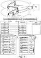
- FIG. 1 schematically shows a wireless communication system and exemplary block diagrams of UE, eNB and MME in accordance with a novel aspect of the invention.
- Macro cell 131 and macro cell 132 are adjacent cells served by eNB 111 and eNB 112 respectively.
- eNB 111 and eNB 112 are connected with each other with a X2 link.
- Pico cell 133 is within macro cell 132 and is served with eNB 113.
- eNB 112 and eNB 113 are connected with each other with an X2 link.
- Each of the eNBs, eNB 111, eNB 112 and eNB 113 connects with Mobility Management Entity MME 121 via S1 links.
- UE 101 is at the cell edge of cell 131 and cell 132. It is likely that UE 101 can receive signals from ENB 111 via L1 and signals from ENB 112 via L2. Instead of hand over to another cell, UE 101 can use inter-eNB carrier aggregation to maintain two connections of L1 and L2 with eNB 111 and eNB 112.
- the initial configuration of aggregating L1 and L2 can be done by the initial serving cell and the consequent configuration of inter-eNB carrier components can be done by one cell or done by each cell.
- the X2 interface between eNB 111 and eNB 112 can be configured to transfer additional control signals or data to support inter-eNB carrier aggregation on connections L1 and L2.
- UE 102 connects to eNB 113 in Pico cell 133 via link L4, while maintaining connection with eNB 112 in macro cell 132 via L3.
- Inter-eNB aggregation can use signals from L3 and L4 to serve UE 102.
- the X2 interface between eNB 112 and eNB 113 can be configured to transfer additional control signals or data to support inter-eNB carrier aggregation on connections L3 and L4.
- Figure 1 further shows exemplary block diagrams illustrating protocol stacks of UE 141, eNodeB 142 and MME 143.
- UE 141 has a physical layer stack (PHY), Mac layer (MAC), Radio Link Control (RLC), Packet Data Control Protocol (PDCP), Radio Resource Control (RRC) and Non Access Stratum (NAS) layer.
- eNodeB 142 has corresponding protocol stacks that communicates with UE 141, include PHY, MAC, RLC, PDCP and RRC.
- the NAS protocol stack is transparent to eNodeB 142.
- the corresponding NAS protocol stack is on MME 143.
- Figure 1 further shows exemplary block diagrams of UE 141 and eNodeB 142 that supports some embodiments of the present invention.
- UE 141 has RF transceiver module 150, coupled with antenna 171 receives RF signals from antenna 171, converts them to baseband signals and sends them to processor 151.
- RF transceiver 150 also converts received baseband signals from the processor 151, converts them to RF signals, and sends out to antenna 171.
- Processor 151 processes the received baseband signals and invokes different functional modules to perform features in UE 141.
- Memory 152 stores program instructions and data to control the operations of UE 141.
- Figure 1 further illustrates seven functional modules 153 to 159, which carry out embodiments of the present invention.
- Link connection Module 153 establishes links with multiple points or multiple eNBs to support multi-point carrier aggregation.
- Aggregation module 154 aggregates multiple component carriers from different eNBs.
- MM function module 155 performs mobility management functions.
- Configuration module 156 performs necessary configuration for inter-eNB carrier aggregation including configure multiple UE-IDs.
- Decoding module 157 decodes received data streams.
- Feedback module 158 generates feedback information and feedback channels.
- Combining module 159 performs combining multiple data streams from multiple data path in an inter-eNB carrier aggregation system.
- eNodeB 142 has RF transceiver module 160, coupled with antenna 172 receives RF signals from antenna 172, converts them to baseband signals and sends them to processor 161.
- RF transceiver 160 also converts received baseband signals from the processor 161, converts them to RF signals, and sends out to antenna 172.
- Processor 161 processes the received baseband signals and invokes different functional modules to perform features in eNodeB 142.
- Memory 162 stores program instructions and data to control the operations of eNodeB 142.
- Figure 1 further illustrates six functional modules 163 to 168 in eNodeB 142 that carry out embodiments of the current invention.
- Link connection module 163 manages multiple connections from different eNBs in a inter-eNB carrier aggregation system.
- Configuration module 164 performs configurations for multi-point carrier aggregation, including component carrier configuration and UE-ID configuration.
- Aggregation module 165 aggregates multiple data streams.
- MM Function module 166 performs mobility management functions.
- Combining module 167 combines multiple data streams in accordance embodiments of the invention.
- Distributing module 168 distribute data streams to other eNBs in an inter-eNB carrier aggregation system.
- inter-eNB carrier aggregation applies in many scenarios. For example, when a UE is at the edge of two neighboring macro cells, or when a UE is in a Pico cell while keeping its connection with a macro cell.
- the following figures show some exemplary scenarios of the above cases.
- Figures 2A and 2B show exemplary scenarios of macro cell to macro cell uplink and downlink cases.
- Figures 3A to 3C show exemplary scenarios of macro-Pico cell cases for downlink carrier aggregation and
- Figure 4 shows exemplary macro-Pico case for uplink carrier aggregation.
- Figure 2A shows an exemplary scenario when uplink and downlink carrier aggregation applies in macro cell to macro cell cases, where both macro cells transmit signals on F1 and F2.
- Cell 206 served with eNB 202 transmits on F1 and F2.
- Neighboring Cell 207 served with eNB 203 also transmits on F1 and F2.
- UE 204 stationed in cell 206 can detect both F1 and F2.
- UE 205 in cell 207 can detect both F1 and F2.
- UE 201 which is at the cell edge of cell 206 and cell 207, may receive better signals on F1 from eNB 202 in cell 206 and F2 from eNB 203 in cell 207.
- UE 201 Assuming UE 201 is served by F1 in cell 206, it is beneficial using inter-eNB carrier aggregation for UE 201 by aggregating CCs on F1 from cell 206 and F2 from cell 207.
- UE 201 can aggregate both or any one of uplink and downlink CCs on F1 from cell 206 and F2 from 207. Similar variations with a few frequency layers than shown in figure 2A can apply the same principles. For example, cell 206, the current serving cell for UE 201 transmits on F1 and F2, and cell 207, the neighboring cell, transmits on F2. While connecting with eNB 202 in cell 206, UE 201 at the cell edge receives better signals from F1 in cell 206 and F2 from cell 207. Aggregating uplink and/or downlink CCs on F1 in cell 206 and F2 in cell 207 would be beneficial for UE 201.
- Figure 2B shows an exemplary scenario when uplink and downlink carrier aggregation apply in macro cell to macro cell cases, where one cell transmits signals on F1 and the other transmits signals on F2.
- Cell 216 served with eNB 212 transmits on F1.
- Neighboring Cell 217 served with eNB 213 transmits on F2.
- UE 214 stationed in cell 216 detects F1.
- UE 215 in cell 217 detects F2.
- UE 211 which is at the cell edge of cell 216 and cell 217, may receive better signals on F1 from eNB 212 in cell 216 and F2 from eNB 213 in cell 217.
- UE 211 Assuming UE 211 is served by F1 in cell 216, it is beneficial using inter-eNB carrier aggregation for UE 211 by aggregating CCs on F1 from cell 216 and F2 from cell 217.
- UE 211 can aggregate both or any one of uplink and downlink CCs on F1 from cell 216 and F2 from 217.
- Inter-eNB carrier aggregation is not only useful for UEs at macro cell edges, but also useful in other cases, like macro-Pico cell cases as shown below.
- Figures 3A to 3C show some exemplary cases for macro-Pico cell down link carrier aggregation cases.
- Figure 4 shows an exemplary case for macro-Pico cell uplink carrier aggregation.
- Figure 3A shows an exemplary scenario when downlink carrier aggregation applies in macro-Pico cell cases, where the macro cell transmits signals on F1 with cell id 0, and the Pico cell transmits signals on F2 with cell id 1.
- UE 301 is within the range of Pico cell 305, which is inside macro cell 304.
- eNB 302 of macro cell 304 transmits on F1 only with cell id of 0.
- eNB 303 of Pico cell 305 transmits on F2 only with cell id of 1.
- UE 301 benefit from inter-eNB carrier aggregation as it receives good signals from both F1 in cell 304 and F2 in cell 305.
- One exemplary configuration can be use F1 as the mobility layer and F2 as the throughput/capacity enhancement layer. Mobility management functions are carried on F1 only so that frequent handover can be avoided and aggregated component carriers on F2 can enhance UE 301's throughput. Other similar configurations of the macro-Pico cell scenario apply similarly.
- Figure 3B shows an exemplary scenario when downlink carrier aggregation applies in macro-Pico cell cases, where the macro cell transmits signals on F1 only with cell id 0, and the Pico cell transmits signals on F1 and F2 with cell id 1 and cell id 2, respectively.
- UE 311 is within the range of Pico cell 315, which is inside macro cell 314.
- eNB 312 of macro cell 314 transmits on F1 only with cell id of 0.
- eNB 313 of Pico cell 315 transmits on F1 and F2 with cell id 1 and cell id 2, respectively.
- UE 311 benefits from inter-eNB carrier aggregation as it receives good signals from both F1 in cell 314 and F2 in cell 315.
- One exemplary configuration is to use F1 from macro cell 314 as the mobility layer and F2 from Pico cell 315 as the throughput/capacity enhancement layer. Mobility management functions are carried on F1 only so that frequent handovers can be avoided and aggregated component carriers on F2 can enhance UE 311's throughput. Since both macro cell 314 and Pico cell 315 transmits on F1 coordinated multipoint (CoMP) can be applied to F1 to resolve interference problem between macro cell 314 and Pico cell 315. Other similar configurations of the macro-Pico cell scenario apply similarly.
- CoMP coordinated multipoint
- Figure 3C shows an exemplary scenario when downlink carrier aggregation applies in macro-Pico cell cases, where the macro cell transmits signals on F1 with cell id 0, and the Pico cell transmits signals on F2 with cell id 1 and F1 with the same cell id 0.
- UE 321 is within the range of Pico cell 325, which is inside macro cell 324.
- eNB 322 of macro cell 324 transmits on F1 only with cell id of 0.
- eNB 323 of Pico cell 325 transmits on F1 and F2 with cell id 0 and cell id 1, respectively.
- UE 321 benefits from inter-eNB carrier aggregation as it receives good signals from both F1 in cell 324 and F2 in cell 325.
- One exemplary configuration is to use F1 from macro cell 324 as the mobility layer and F2 from Pico cell 325 as the throughput/capacity enhancement layer. Mobility management functions are carried on F1 only so that frequent handover can be avoided and aggregated component carriers on F2 can enhance UE 321's throughput. Since both macro cell 324 and Pico cell 325 transmit on F1 coordinated multipoint (CoMP) can be applied to F1 to resolve interference problem between macro cell 324 and Pico cell 325. Other similar configurations of the macro-Pico cell scenario apply similarly.
- CoMP coordinated multipoint
- Inter-eNB carrier aggregation for uplink component carriers has similar scenarios.
- Figure 4 shows an exemplary scenario when uplink carrier aggregation applies in macro-Pico cell cases, where the macro cell transmits signals on F1 with cell id 0, and the Pico cell transmits signals on F2 with cell id 1.
- eNB 402 of macro cell 404 transmits on F1 only with cell id of 0.
- eNB 403 of Pico cell 405 transmits on F2 only with cell id of 1.
- UE 401 benefits from inter-eNB carrier aggregation as it receives good signals from both F1 in cell 404 and F2 in cell 405.
- One exemplary configuration can be use F1 as the mobility layer and F2 as the throughput/capacity enhancement layer.
- Inter-eNB carrier aggregation offers many benefits. However, current LTE system does not fully support it. The first issue is control plane operations. In current LTE systems, there is only one RRC connection served by the primary cell (PCell). The PCell is the first cell that the UE establishes RRC connection with. Afterwards, one or more secondary cells (SCell) can be configured. For inter-eNB carrier aggregation, the SCell can be from the same eNB as the PCell, or can be from a different eNB. Scell configuration of inter-eNB CA scenario should be addressed.
- PCell primary cell
- SCell secondary cells
- Scell configuration of inter-eNB CA scenario should be addressed.
- FIG. 5 shows an exemplary diagram of inter-eNB SCell configuration.
- UE 501 is at cell edges of cell 521 and cell 522.
- eNB 502 serves cell 521 and eNB 503 serves cell 522.
- UE 501 receives good signals from cell 521 via eNB 502and cell 522 via eNB 503.
- UE 501 establishes connection with cell 521 via eNB 502.
- An RRC connection is established between UE 501 and cell 521.
- Component Carrier #1 in a link connected with eNB 502 is configured by eNB 502. Since there is only one RRC connection, component carrier #2 in a link connected with eNB 503 needs X2 information change. Therefore, at Step 512, eNB 503 configures component carrier #2.
- eNB 503 forwards the CC #2's information to eNB 502 via X2 interface.
- eNB 502 at Step 514, sends configuration message to UE 501 to do the initial configuration for component carrier #2.
- the primary eNB (PeNB), and eNB 503, the secondary eNB (SeNB) can further configure its SCells independently.
- TA multiple-Timing Advance
- cells that belong to the same eNB can be configured as one TA group.
- network can be configured to be refrained from grouping cells from different eNBs into one TA group.
- inter-eNB CA When UE is configured with inter-eNB CA, it can receive signals from PeNB and SeNB for RRC connection management messages. Since there is only RRC connection for the UE, there are two types of configuration for inter-eNB CA.
- FIG. 6A shows an exemplary block diagram of protocol stacks for PeNB and SeNB for a configuration where RRC messages can be transferred on both the eNBs.
- UE 601 connects with eNB 602 via link 604.
- UE 601 also connects with eNB 603 via link 605.
- eNB 602 is the PeNB and eNB 603 is the SeNB.
- eNB 602 and eNB 603 are connected with X2 interface.
- UE 601 receives RRC messages from both the PeNB and the SeNB on links 604 and link 605.
- Both the PeNB and the SeNB handle the PHY, MAC, RLC, PDCP and RRC stacks for this connection.
- eNB 602 and eNB 603 both carry RRC messages
- the Mobility Management function is only performed at PeNB because a UE maintains NAS contexts only from PCell. Therefore, PeNB is the only eNB to handle all the Mobility Management related messages. Therefore, link 604 is the only link that carries MM messages, including measurement reporting and handover command. Even if eNB 603, the SeNB with RRC connection with UE 601, can directly send RRC command to UE 601, it cannot send mobility-related messages. If one of the SCells connected to the SeNB encounters bad channel condition, no RRC re-establishment is required. In general, in these cases, the spontaneous UL transmission is not allowed. Instead, light-weighted Radio Link Monitor function on SCells can be applied.
- an uplink CC on the primary link can be configured as the feedback channel for both the downlink CC in both eNBs.
- the feedback information is carried on the primary uplink CC only.
- RLM function is performed on the primary connection. Cell reselection is only performed when radio link fails on the primary connection.
- an uplink CC is configured for each eNB that carries feedback information for their corresponding downlink CCs. RLM function can be performed on both the primary and the second connection. Cell reselection function, however, is only performed on the primary connection when the primary radio link fails.
- FIG. 6B shows an exemplary block diagram of protocol stacks for PeNB and SeNB for a configuration of RRC messages can be transferred only on the PeNB.
- UE-611 connects with eNB 612 via link 614.
- UE 611 also connects with eNB 613 via link 615.
- eNB 612 is the PeNB and eNB 613 is the SeNB.
- eNB 612 and eNB 613 are connected with X2 interface.
- UE 611 receives RRC messages from the PeNB only.
- the PeNB handles the PHY, MAC, RLC, PDCP and RRC stacks for this connection.
- the SeNB only handles PHY, MAC and RLC layers for this connection. In this configuration, additional X2 exchanges are needed. Since RRC connection is only carried on link 614 to the PeNB, the mobility management messages as well as other RRC messages are carried only on link 614.
- C-RNTI is the UE-ID that is assigned when UE camps on its serving cell (i.e., PCell).
- PCell serving cell
- C-RNTI is the UE-ID that is assigned when UE camps on its serving cell (i.e., PCell).
- PCell serving cell
- SCell multiple SCells.
- Such configuration works when all the component carriers are connected to the same eNB.
- component carriers are aggregated from different eNBs, multiple C-RNTIs are desired because the C-RNTI assigned in PCell may have already been used by another UE in the SCell. Therefore, assigning different UE-IDs for an UE is needed.
- FIG. 7 shows a flow diagram in accordance with one embodiment of the invention that a second UE-ID is assigned via RRC signaling from PCell.
- UE 701 connects with primary eNB 702 and secondary eNB 703.
- UE 701 is configured for inter-eNB carrier aggregation.
- Primary eNB 702 and Secondary eNB 703 connect with MME 704 via S1 links.
- UE 701 establishes connection with primary eNB 702 via RACH process.
- Primary eNB 702 assigns a first C-RNTI to UE 701.
- UE sends RRC Connection Request message to primary eNB 702.
- primary eNB 702 replies with RRC Connection Setup message.
- the RRC connection between UE 701 and eNB 702 is established.
- Primary eNB 702 proceeds to set up data path with MME 704 by sending S1 Data Path Request to MME 704 at Step 714.
- MME 704 replies with S1 Path Switch ACK message.
- primary eNB 702 communicates with secondary eNB 703 via X2 interface to perform inter-eNB configuration.
- the communication may include a negotiation process to coordinate a second C-RNTI number for UE 701 for its connection with secondary eNB 703.
- Various other negotiation and configuration can be done during this negotiation to set up CA between primary eNB 702 and secondary eNB 703.
- primary eNB 702 sends a RRC reconfiguration message to UE 701 for inter-eNB CA configurations.
- UE 701 connects with secondary eNB 703 via RACH process.
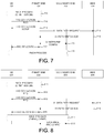
- FIG. 8 shows a flow diagram in accordance with one embodiment of the invention that a second UE-ID is assigned via MAC signaling during SCell RACH procedure.
- UE 801 connects with primary eNB 802 and secondary eNB 803, and UE 801 is configured for inter-eNB carrier aggregation.
- Primary eNB 802 and Secondary eNB 803 connect with MME 804 via S1 links.
- UE 801 establishes connection with primary eNB 802 via RACH process.
- Primary eNB 802 assigns a first C-RNTI to UE 801.
- UE sends RRC Connection Request message to primary eNB 802.
- primary eNB 802 replies with RRC Connection Setup message.
- the RRC connection between UE 801 and eNB 802 is established.
- Primary eNB 802 proceeds to set up data path with MME 804 by sending S1 Data Path Request to MME 804 at Step 814.
- MME 804 replies with S1 Path Switch ACK message.
- primary eNB 802 sends a RRC reconfiguration message to UE 801 for inter-eNB CA configurations.
- UE 801 connects with secondary eNB 803 via RACH process.
- Secondary eNB 803 configures UE 801 with a second C-RNTI together with timing information.
- primary eNB 802 and secondary eNB 803 exchanges configured RRC parameters to complete the inter-eNB UE identity configuration.
- FIG. 9 is an exemplary flow diagram in accordance to embodiments of the current invention that configures control plane parameters for an inter-eNB carrier aggregation.
- An eNB at Step 901, establishes a primary connection with a UE in a primary cell belonging to a primary base station with a first UE-ID, wherein the primary cell comprises a downlink component carrier (CC) and an uplink component carrier.
- the eNB at Step 902, configures a second connection with the UE in a second cell belonging to a second base station, wherein the secondary cell comprises a downlink CC and an optional uplink CC.
- the eNB configures and aggregates component carriers (CCs) of the primary cell and the secondary cell for the primary connection and the second connection.
- mobility management functions are performed through the primary connection.
- inter-eNB CA U-plane configurations.
- inter-eNB CA when UE or network receives data from multiple frequency layers or sends signals to multiple frequency layers, configuration and signal combination or multiplexing issues need to be addressed. There are two main categories of issues. The first is which entity to terminate the data path. The second is how to aggregate these received data.
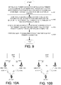
- FIG. 10A shows an exemplary diagram in accordance with one embodiment of the invention where the MME is configured to be the aggregating entity, also called anchor entity. Since data could be transmitted over both PCell connection and SCell connection, anchor entity is needed.
- UE 1001 connects with eNB 1002 and eNB 1003 via connections 1005 and 1006, respectively. Carrier aggregation is configured on connection 1005, which is on F1 and connection 1006, which on F2.
- eNB 1002 and eNB 1003 connect to each other via X2 interface.
- MME 1004 connects with eNB 1002 and eNB 1003 via S1 links. In this configuration, MME establishes two dedicated S1 links 1007 and 1008.
- eNB 1002 and eNB 1003 handles data packets separately without coordination.
- a network entity like MME 1004, is configured to be the anchor entity to handle aggregation of data packets from eNB 1002 and eNB 1003.
- MME 1004 as the anchor entity, needs to handle addition signaling overhead and to handle more than one data path for UE 1001. Additional impacts and overhead are added to MME 1004 and S1 links 1007 and 1008.
- MME 1004 upon changing of a SCell, MME 1004 needs to re-establish new data path with the new SCell. Such operation, however, is transparent to eNBs and has less impact on eNB operation.
- FIG. 10B shows an exemplary diagram in accordance with one embodiment of the invention where an eNB is configured to be the aggregating entity, also called anchor entity.
- UE 1011 connects with eNB 1012 and eNB 1013 via connections 1015 and 1016, respectively.
- Carrier aggregation is configured on connection 1015, which is on F1 and connection 1016, which on F2.
- eNB 1012 and eNB 1013 connect to each other via X2 interface.
- a network entity like MME 1014, connects with eNB 1012 and eNB 1013 via S1 links.
- eNB 1012 is configured as the anchor entity. Note that, in the example, eNB1012 is the PeNB of UE1011.
- MME establishes only one dedicated S1 link 1017 that connects with eNB 1012.
- eNB 1013 uses X2 interface to forward the data streams to anchor eNB 1012. This operation is transparent to MME 1014.
- the anchor eNB, eNB 1012 needs to handle the data forwarding function via X2 interface. It has less impact on S1 interface and less impact on MME. However, additional data transfer and handling are required on the X2 interface.
- eNB anchoring is a preferable solution because S1 connection setup incurs more signaling overheads.
- FIG 11 shows a flow chart in accordance with one embodiment of the current invention, where two MME-eNB connections are established for inter-eNB carrier aggregation.
- UE 1101 is connected with primary eNB 1102 and secondary eNB 1103 for inter-eNB carrier aggregation.
- Primary eNB 1102 and secondary eNB 1103 connect to a network entity, e.g. MME 1104, via S1 links.
- MME 1104 e.g. MME 1104
- S1 links e.g. MME 1104
- two S1 data links are established because the network entity is configured to be the anchor entity.
- UE 1101 establishes connection with primary eNB 1102 on a primary cell.
- UE 1101 establishes connection with secondary eNB 1103 on a secondary cell.
- RRC connection is also established for UE 1101.
- primary eNB 1102 sends S1 Data Path Request to MME 1104.
- MME 1104 replies with S1 Data Path Ack.
- the data path between primary eNB 1102 and MME 1104 is established for UE 1101.
- UE 1101 starts data transmission to primary eNB 1102.
- secondary eNB 1103 sends S1 Data Path Request to MME 1104.
- MME 1104 sends S1 Data Path ACK to secondary eNB 1103.
- the data path between secondary eNB 1103 and MME 1104 is established for UE 1101.
- UE 1101 starts data transmission to secondary eNB 1103.
- Figure 12 shows a flow chart in accordance with one embodiment of the current invention, where only one MME-eNB connection is established via the primary eNB.
- UE 1201 is connected with primary eNB 1202 and secondary eNB 1203 for inter-eNB carrier aggregation.
- Primary eNB 1202 and secondary eNB 1203 connect to a network entity, like MME 1204, via S1 links. In this configuration, only one S1 data link is established because the primary eNB 1202 is configured to be the anchor entity.
- UE 1201 establishes connection with primary eNB 1202 on a primary cell.
- UE 1201 establishes connection with secondary eNB 1203 on a secondary cell.
- primary eNB 1202 sends S1 Data Path Request to MME 1204.
- MME 12104 replies with S1 Data Path Ack.
- the data path between primary eNB 1202 and MME 1204 is established for UE 1201.
- X2 data path is established between primary eNB 1202 and secondary eNB 1203 via X2 interface.
- data transmission starts between UE 1201 and primary eNB 1202 starts.
- data transmission starts between UE 1201 and secondary eNB 1203 starts.
- primary eNB 1202 will combine data from itself with data from secondary eNB 1203 and forward to the network entity like MME 1204.
- link layer e.g., radio link control (RLC) layer or packet data convergence protocol (PDCP) layer.
- RLC radio link control
- PDCP packet data convergence protocol
- two categories of data transmission/reception schemes can be used and configured for inter-eNB carrier aggregation. These two categories of schemes apply to both the configuration of PeNB as the anchor entity and the configuration of network entity as the anchor entity.
- the first category of method is a multiplexing scheme when different data contents in bit-level are to/from different cells.
- For downlink transmission after UE receives data packets from the two connections, it does not perform data combination in link control layer to reassemble original data stream.
- the original data streams e.g., packets generated from applications
- PeNB When PeNB is configured as the anchor entity, it uses multiplexing scheme when the received uplink data from PeNB and SeNB are different. In such configuration, PDCP function is handled at PeNB.
- RLC of PeNB and SeNB handle data assembling function for its respective connection independently. PeNB RLC assembles different data stream from eNBs and forward to the network entity.
- PeNB RLC or PDCP handles packet segmentation. PeNB forwards the segmented data streams to secondary eNBs.
- MME is configured as the anchor entity, the assembly and segmentation are done at the MME.
- the second category of scheme is soft combining. Such scheme applies when the data contents are the same at bit-level to/from different connections. In this scheme, soft combining at bit-level can be applied.
- For downlink transmission after UE receives data bits from the two connections, it performs soft combination to decode data packets. Although the data bits are received from different frequency layer, it is possible to apply bit-level combining to enhance the received Signal to Interference Ratio (SIR).
- SIR Signal to Interference Ratio
- For uplink transmission when the primary eNB is configured as the anchor entity, it combines multiple data bit streams from eNBs and performs bit-level soft combining. PeNB then forward the data to the network entity, e.g., ME. When MME is configured to be the anchor entity, it performs soft combining upon receiving multiple bit streams from different data path connecting with eNBs. In general, using such scheme can have combining gain. Diversity gain can be achieved if selective combination is applied.
- a UE can be configured to use either of the above two categories of data reception/transmission schemes in a similar manner.
- the UE When the UE is configured to receive different data contents at bit-level from different eNBs, it applies the multiplexing scheme as described above.
- the UE When the UE is configured to receive the same data contents at bit-level from different eNBs, it applies soft combining scheme as described above. In one example, the UE first generates a bit stream by soft combining multiple bits streams from different data path, and then reassembles a data stream by decoding the soft-combined bit stream.
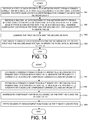
- FIG. 13 shows a flow chart in accordance with some embodiments of the current invention where an eNB is configured to be the anchor entity to handle multiple data streams in an inter-eNB carrier aggregation system.
- An anchor eNB receives a first UE data destined to a network entity from a primary connection with an UE in a first cell belonging to a first base station, wherein the first base station is configured to be an anchor entity.
- the anchor eNB receives a second UE data destined to the network entity from a second connection with a second base station, wherein the second base station is connected with the UE in a second cell, wherein component carriers in the first and the second cell are aggregated to serve the UE. It then combines the first UE data and the second UE data.
- the anchor eNB would distribute a third UE data received from the network entity to the first and the second base station, wherein the third data is destined to the UE.
- FIG 14 shows a flow chart in accordance with some embodiments of the current invention where the UE receives multiple data streams in an inter-eNB carrier aggregation system.
- a UE at Step 1401, establishes a primary connection in a primary cell belonging to a primary base station with a first UE-ID, wherein the primary cell comprises a downlink component carrier (CC) and an uplink CC.
- the UE establishes a second connection in a second cell belonging to a second base station with a second UE-ID, wherein the secondary cell comprises a downlink CC and an optional uplink CC.
- the UE at Step 1403, aggregates component carriers (CC) based on the first UE-ID and the second UE-ID.
- the UE performs Mobility Management functions on the primary connection.
- the third issue for inter-eNB carrier aggregation is downlink and uplink component carrier scheduling.
- UE-ID e.g., C-RNTI
- different CCs are aggregated from different base stations and different UE-IDs may apply for different CCs and different schedulers. If UE is allowed to hold multiple cell-specific UE-ID or different C-RNTI for downlink CC connecting to different base stations, the downlink scheme requires corresponding modifications. UE needs to hold multiple UE-IDs to search for downlink schedulers and downlink CCs.
- the first is to assign the same UE-ID for all CCs connecting with the same base station. In this option, which set of CCs belongs to the same base station may be transparent to an UE.
- the network can just configures an UE which set of CCs uses the same UE-ID or C-RNTI by higher-layer signaling and UE will just follow the higher-layer configuration for the detection of downlink control information and data reception or transmission.
- the second is to assign a different UE-ID for different CCs. In either scheme, improvement needs to be made to the current system at the physical layer to implement inter-eNB CA.
- the following sessions describe some exemplary configurations of downlink and uplink CC scheduling.
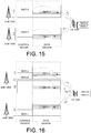
- FIG. 15 shows an exemplary diagram in accordance to one embodiment of the invention, when non-cross-carrier scheduling is used for downlink CC scheduling in an inter-eNB carrier aggregation system.
- UE 1501 is configured for inter-eNB carrier aggregation. It is configured with two UE-IDs, RNTI-0 and RNTI-1. UE needs to store these configured UE-IDs.
- UE 1501 connects with eNB 1502 and eNB 1503. Downlink component carriers from eNB 1502 transmit on F1.
- RNTI-0 is assigned to data region of DL CC on F1.
- Downlink component carriers from eNB 1503 transmit on F2.
- RNTI-1 is assigned to data region of DL CC on F2.
- each DL CC's control region schedules the data region DL CC.
- control region RNTI-0 scheduler points to data region in data region of the same DL CC with the same RNTI-0.
- control region RNTI-1 scheduler points to data region in data region of the same DL CC with the same RNTI-1.
- UE 1502 only needs to know the coupling between cell-specific UE-ID, like RNTI and the component carriers.
- Each base station can optionally assign different UE-ID to its DL CCs.
- UE 1501 receives aggregated DL CCs on F1 and F2.
- UE 1501 cannot assume that the UE-IDs applied for all DL CCs are the same.
- UE 1501 will search for the DL scheduler(s) on each DL CC with corresponding configured UE-IDs.
- FIG. 16 shows an exemplary diagram in accordance to one embodiment of the invention, where cross-carrier scheduling is only used for intra-eNB carrier components for downlink CC scheduling in an inter-eNB carrier aggregation system.
- UE 1601 is configured for inter-eNB carrier aggregation. It is configured with two UE-IDs, RNTI-0 and RNTI-1. UE needs to store these configured UE-IDs.
- UE 1601 connects with eNB 1602 and eNB 1603. Downlink component carriers from eNB 1602 transmit on F1 and F3.
- RNTI-0 is assigned to the data region of DL CC on F1 and F3.
- Downlink component carriers from eNB 1603 transmit on F2.
- RNTI-1 is assigned to the data region of DL CC on F2.
- cross-carrier scheduling is used only for intra-eNB cases.
- control region RNTI-0 scheduler schedules a DL CC on F1 with RNTI-0 and another CC on F3 with RNTI-0.
- F1's DL CC schedules CCs on the same DL CC and on another DL CC transmitted on F3.
- the cross-carrier scheduling only applies for the DL CCs connect to the same eNB.
- control region of DL CC on F2 with RNTI-1 schedules same DL CC with the same RNTI-1. In this case, cross-carrier scheduling is limited to intra-eNB DL CCs.
- the eNB can assign different UE-ID to different CCs.
- eNB 1602 can assign RNTI-0 to DL CC on F1, and a RNTI-2 for DL CC on F3. If intra-eNB cross-carrier scheduling applies, the control region of DL CC on F1 with RNTI-0 will schedule the DL CC on F2 with RNTI-2. UE will need to store all the configured UE-IDs. In the later optional configuration, UE 1601 will store RNTI-0, RNTI-1, and RNTI-2. UE receives aggregated CCs on F1, F2 and F3. UE 1601 cannot assume that the UE-IDs applied for all DL CCs are the same. UE 1601 searches and detects the DL scheduler(s) based on the assigned UE-IDs on each downlink CC.
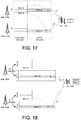
- FIG. 17 shows an exemplary diagram in accordance to one embodiment of the invention, where cross-carrier scheduling is used for inter-eNB carrier components for downlink CC scheduling in an inter-eNB carrier aggregation system.
- UE 1701 is configured for inter-eNB carrier aggregation. It is configured with two UE-IDs, RNTI-0 and RNTI-1. UE needs to store these configured UE-IDs.
- UE 1701 connects with eNB 1702 and eNB 1703. Downlink component carriers from eNB 1702 transmit on F1.
- RNTI-0 is assigned to the data region of DL CC on F1.
- Downlink component carriers from eNB 1703 transmit on F2.
- RNTI-1 is assigned to the data region of DL CC on F2.
- cross-carrier scheduling is used for inter-eNB cases.
- control region RNTI-0 scheduler schedules a DL CC on F1 with RNTI-0 and DL CC on F3 with RNTI-1, which is connected with a different eNB.
- F1's DL CC schedules CCs on the same DL CC and on another DL CC connected with a different eNB.
- the cross-carrier scheduling applies for the inter-eNB DL CCs.
- cross-carrier scheduling applies to inter-eNB DL CCs. It is optional that the eNB can assign different UE-ID to different CCs. UE will need to store all the configured UE-IDs.
- UE 1701 cannot assume that the UE-IDs applied for all DL CCs are the same. UE 1701 searches and detects the DL scheduler based on the assigned UE-IDs on each downlink CC. In such configuration, inter-eNB coordination on UE-ID assignment is not needed to avoid UE-ID confusion.
- uplink grant in an inter-eNB carrier aggregation requires modifications.
- Uplink grants are carried in DL component carriers' control region. There are cases that an uplink CC is linked with a downlink CC.
- the UE-ID for the DL CC where the uplink grant resides maybe different from the UE-ID for the uplink CC. Different configuration can be used.
- the following session shows some exemplary configurations for uplink grant in an inter-eNB carrier aggregation system.
- FIG. 18 shows an exemplary diagram in accordance to one embodiment of the invention, where non-cross-carrier scheduling is used for uplink CC grant in an inter-eNB carrier aggregation system.
- UE 1801 is configured for inter-eNB carrier aggregation. It is configured with two UE-IDs, RNTI-0 and RNTI-1. UE 1801 needs to store these configured UE-IDs.
- UE 1801 connects with eNB 1802 and eNB 1803.
- eNB 1802 transmits downlink on F1 and uplink on F3.
- the DL CC on F1 is linked with the UL CC on F3 via the UL-DL linking.
- DL CC on F1 and UL CC on F3 are assigned UE-ID of RNTI-0.
- eNB 1803 transmits downlink on F2 and uplink on F4.
- the DL CC on F2 is linked with the UL CC on F4 via the UL-DL linking.
- DL CC on F2 and UL CC on F4 are assigned UE-ID of RNTI-1.
- the downlink component carrier where the uplink grant resides connects to the same base station as the linked uplink component carrier where the granted uplink data traffic resides.
- Each uplink CC is granted by its linked downlink CC.
- the uplink grants for uplink CC on F3 resides in its linked DL CC on F1.
- the two linked component carriers are assigned with the same UE-ID, RNTI-0.
- the uplink grants for uplink CC on F4 resides in its linked DL CC on F3.
- the two linked component carriers are assigned with the same UE-ID, RNTI-1.
- UE 1801 stores the configured UE-IDs, RNTI-0 and RNTI-1.
- UE 1801 searches and detects the uplink grant based on the assigned UE-ID on each downlink component carrier.
- UE 1801 transmits on uplink CCs carried on F3 and F4.
- FIG 19 shows an exemplary diagram in accordance to one embodiment of the invention, where cross-carrier scheduling is only used for intra-eNB uplink CC grant in an inter-eNB carrier aggregation system.
- UE 1901 is configured for inter-eNB carrier aggregation. It is configured with two UE-IDs, RNTI-1 and RNTI-2. UE 1901 needs to store these configured UE-IDs.
- UE 1901 connects with eNB 1902 and eNB 1903.
- eNB 1902 transmits downlink on F1 and uplink on F3.
- the DL CC on F1 is linked with the UL CC on F3 via the UL-DL linking.
- DL CC on F1 and UL CC on F3 are assigned UE-ID of RNTI-0.
- eNB 1903 transmits downlink on F1 and uplink on F3.
- the DL CC on F1 is linked with the UL CC on F3 via the UL-DL linking.
- DL CC on F1 and UL CC on F3 are assigned UE-ID of RNTI-1.
- eNB 1903 also transmits downlink on F2 and uplink on F4.
- the DL CC on F2 is linked with the UL CC on F4 via the UL-DL linking.
- DL CC on F2 and UL CC on F4 are assigned UE-ID of RNTI-2.
- the downlink component carrier where the uplink grant resides connects to the same base station as the uplink component carrier where the granted uplink data traffic resides.
- the downlink CC where the uplink grant resides may not be linked with the uplink CC that carries the uplink data.
- downlink CC on F1 with RNTI-1 has uplink grant for its linked UL CC on F3 with RNTI-1.
- This downlink CC also carries uplink grant for uplink CC on F4 with RNTI-2, which is not linked with this downlink CC.
- cross-carrier scheduling is limited within the same eNB.
- UE 1901 stores the configured UE-IDs, RNTI-1 and RNTI-2 for uplink grants.
- UE 1901 searches and detects the uplink grant based on the assigned UE-ID on each downlink component carrier.
- UE 1901 transmits on uplink CCs carried on F3 and F4.
- the same eNB, eNB 1903 assigns two different UE-IDs to its component carries.
- UE 1901 is configured for inter-eNB CA and is connected with both eNB 1902 and eNB 1903, it is only transmitting to eNB 1903.
- UE 1901 may aggregate CCs from both the eNB 1902 and eNB 1903 for downlink CC, while only transmitting on cells in one eNB. Such configuration is useful in cases like macro-Pico cell configurations.
- UE 1901 may store RNTI-0 as well for downlink CC although only RNTI-1 and RNTI-2 are used for uplink carrier aggregation.
- FIG. 20 shows an exemplary diagram in accordance to one embodiment of the invention, where cross-carrier scheduling is used for inter-eNB uplink CC grant in an inter-eNB carrier aggregation system.
- UE 2001 is configured for inter-eNB carrier aggregation. It is configured with two UE-IDs, RNTI-0 and RNTI-1. UE 2001 needs to store these configured UE-IDs.
- UE 2001 connects with eNB 2002 and eNB 2003.
- eNB 2002 transmits downlink on F1 and uplink on F3.
- the DL CC on F1 is linked with the UL CC on F3 via the UL-DL linking.
- DL CC on F1 and UL CC on F3 are assigned UE-ID of RNTI-0.
- eNB 2003 transmits downlink on F2 and uplink on F4.
- the DL CC on F2 is linked with the UL CC on F4 via the UL-DL linking.
- DL CC on F2 and UL CC on F4 are assigned UE-ID of RNTI-1.
- the downlink component carrier where the uplink grant resides may connect to different base station from the uplink component carrier where the granted uplink data traffic resides.
- the downlink CC where the uplink grant resides may not be linked with the uplink CC that carries the uplink data.
- downlink CC on F1 with RNTI-0 has uplink grant for its linked UL CC on F3 with RNTI-0.
- This downlink CC also carries uplink grant for uplink CC on F4 with RNTI-1, which connected with another eNB, eNB 2003.
- cross-carrier scheduling applies to different eNB.
- UE 2001 stores the configured UE-IDs, RNTI-0 and RNTI-1 for uplink grants.
- UE 2001 searches and detects the uplink grant based on the assigned UE-ID on each downlink component carrier.
- UE 2001 transmits on uplink CCs carried on F3 and F4.
- FIG. 21 is a flow chart in accordance with one embodiment of the current invention, where uplink and downlink component carriers are scheduled in an inter-eNB carrier aggregation system.
- a UE at Step 2101 receives an upper layer configuration, wherein a first UE-ID is associated with a first group of downlink (DL) and uplink (UL) component carriers and a second UE-ID is associated with a second group of DL and UL component carriers.
- the UE receives downlink control information via one or more downlink control channels on one or more DL component carriers.
- the UE at Step 2103 decodes the downlink control information using the first UE-ID and the second UE-ID.
- the fourth issue is the configuration of uplink feedback CC for feedback information such as HARQ and CSI.
- the UE may need to hold multiple UE-IDs for downlink and uplink component carriers.
- the HARQ and CSI feedback scheme requires corresponding changes.
- feedback channels can be transmitted in a few different ways to implement inter-eNB carrier aggregation. The first one is to have one uplink component carrier for all feedback channels. Normally the uplink CC that carries all feedback channels is the primary uplink CC. When inter-eNB CA is enabled, such scheme requires inter-eNB data forwarding through X2 interface. The latency of X2 interface may be an issue.
- the second option is to have one uplink component carrier per base station for feedback channels.
- the uplink transmission power efficiency may degrade severely due to the introduced high peak-to-average power ratio (PAPR) in OFDM/OFDMA systems if single RF module is used for the signal transmission on multiple uplink component carriers simultaneously.
- PAPR peak-to-average power ratio
- FIG 22 is a flow chart in accordance with one embodiment of the invention wherein uplink component carriers are configured to carry uplink feedback information in an inter-eNB carrier aggregation system.
- a UE at Step 2201 receives an upper layer configuration, wherein a first uplink feedback component carrier is associated with a first group of downlink component carriers and a second uplink feedback component carrier is associated with a second group of downlink component carriers.
- the UE at Step 2202, aggregates a set of feedback information of downlink component carriers associated with the first and the second uplink feedback component carriers, respectively.
- UE generates uplink feedback channels to carry the aggregated feedback information for the first and the second uplink feedback component carriers.
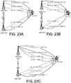
- FIG. 23A shows an exemplary block diagram in accordance with one embodiment of the invention where there is one uplink component carrier for all the downlink component carriers in an inter-eNB carrier aggregation system.
- UE 2301 connects with eNB 2302 and eNB 2303.
- eNB 2302 and eNB 2303 connect with each other via X2 interface.
- UE 2301 is configured with inter-eNB carrier aggregation with two UE-IDs RNTI-0 and RNTI-1 associated with eNB 2302 and eNB 2303, respectively.
- the DL-PCC is the primary downlink component carrier, which is connected with an uplink primary component carrier UL-PCC with RNTI-0.
- One downlink component carrier is configured for eNB 2303: DL-CC-2, with RNTI-1.
- An uplink component carrier UL-CC-2 is configured on eNB 2303 with RNTI-1.
- PUCCH Physical Uplink Control Channel
- X2 interface data forwarding is required.
- FIG. 23B shows an exemplary block diagram in accordance with one embodiment of the invention where there is one uplink component carrier for all the downlink component carriers in the same eNB in an inter-eNB carrier aggregation system.
- UE 2311 connects with eNB 2312 and eNB 2313.
- eNB 2312 and eNB 2313 connect with each other via X2 interface.
- UE 2311 is configured with inter-eNB carrier aggregation with two UE-IDs RNTI-0 and RNTI-1 associated with eNB 2312 and eNB 2313, respectively.
- the DL-PCC is the primary downlink component carrier, which is connected with an uplink primary component carrier UL-PCC with RNTI-0.
- One downlink component carrier is configured for eNB 2313: DL-CC-2, with RNTI-1.
- An uplink component carrier UL-CC-2 is configured on eNB 2313 with RNTI-1.
- one uplink CC is configured to carry feedback information for all DL CCs connected with the same eNB.
- UL-PCC in eNB2312 carries feedback information for DL-PCC and DL-CC-1 in eNB 2312 for feedback information.
- UL-CC-2 in eNB 2313 carries feedback information for DL-CC-2 in eNB 2313.
- Both UL-PCC and UL-CC-2 are configured with PUCCH that carries feedback channels for the component carriers in their respective eNB.
- FIG. 23C shows an exemplary block diagram in accordance with one embodiment of the invention where there is one uplink component carrier for each of its associated downlink component carriers in an inter-eNB carrier aggregation system.
- UE 2321 connects with eNB 2322 and eNB 2323.
- eNB 2322 and eNB 2323 connect with each other via X2 interface.
- UE 2321 is configured with inter-eNB carrier aggregation with two UE-IDs RNTI-0 and RNTI-1 associated with eNB 2322 and eNB 2323, respectively.
- Two downlink component carriers are configured for eNB 2323: DL-CC-2, with RNTI-1 and DL-CC-3 with RNTI-1.
- An uplink component carrier UL-CC-2 is configured on eNB 2313 with RNTI-1.
- one uplink CC is configured to carry feedback information one or more associated DL CCs connected with the same eNB.
- UL-CC-0 in eNB 2322 is associated with DL-CC-0.
- UL-CC-0 carries feedback information for DL-CC-0 in eNB 2322 for feedback information.
- UL-CC-1 in eNB 2322 is associated with DL-CC-1.
- UL-CC-1 carries feedback information for DL-CC-1 in eNB 2322 for feedback information.
- UL-CC-2 in eNB 2323 is associated with DL-CC-2 and DL-CC-3.
- UL-CC-2 carries feedback information for DL-CC-2 and DL-CC-3 in eNB 2313.
- UL-CC-0, UL-CC-1 and UL-CC2 are configured with PUCCH that carries feedback channels for the component carrier in their respective eNB.
Landscapes
- Engineering & Computer Science (AREA)
- Signal Processing (AREA)
- Computer Networks & Wireless Communication (AREA)
- Mobile Radio Communication Systems (AREA)
Claims (8)
- Verfahren aufweisend:Empfangen (2101) von einer Oberschicht-Konfiguration, wobei eine erste UE-Identifikation, UE-ID, mit einer ersten Gruppe von Downlink-, DL, und Uplink-, UL,Komponententrägern und eine zweite UE-ID mit einer zweiten Gruppe von DL- und UL-Komponententrägern verknüpft ist;Empfangen (2102) von einer Downlink-Steuerungsinformation über einen oder mehrere Downlink-Steuerungskanäle auf einem oder mehreren DL-Komponententrägern, wobei die Downlink-Steuerungsinformation ein oder mehrere Downlink-Schedule-Daten aufweist; undDecodieren (2103) der Downlink-Steuerungsinformation unter Verwendung der ersten UE-ID und der zweiten UE-ID,dadurch gekennzeichnet, dass
ein erster DL-Komponententräger, der mit einer ersten Basisstation mit einer ersten UE-ID verbunden ist, durch einen zweiten DL-Komponententräger, der mit einer zweiten Basisstation mit einer zweiten UE-ID verbunden ist, zeitlich gesteuert wird. - Verfahren nach Anspruch 1, bei dem die erste Gruppe von DL- und UL-Komponententrägern mit einer ersten Basisstation und die zweite Gruppe von DL- und UL-Komponententrägern mit einer zweiten Basisstation verbunden sind.
- Verfahren nach Anspruch 1, bei dem die UE-ID ein Cell Radio Network Temporary Identifier, C-RNTI, ist.
- Verfahren nach Anspruch 1, weiter aufweisend:Koordinieren der ersten UE-ID und der zweiten UE-ID in Bezug auf den DL-Scheduler derart, dass der DL-Scheduler den ersten DL-Komponententräger mit der ersten UE-ID zeitlich steuert.
- Verfahren, aufweisend:Empfangen (2101) von einer Oberschicht-Konfiguration, wobei eine erste UE-Identifikation, UE-ID, mit einer ersten Gruppe von Downlink-, DL, und Uplink-, UL,Komponententrägern und eine zweite UE-ID mit einer zweiten Gruppe von DL- und UL-Komponententrägern verknüpft ist;Empfangen (2102) von einer Downlink-Steuerungsinformation über einen oder mehrere Downlink-Steuerungskanäle auf einem oder mehreren DL-Komponententrägern, wobei die Downlink-Steuerungsinformation ein oder mehrere Uplink-Bewilligungen aufweist; undDecodieren (2103) der Downlink-Steuerungsinformation unter Verwendung der ersten UE-ID und der zweiten UE-ID,dadurch gekennzeichnet, dass
ein erster UL-Komponententräger, der mit einer ersten Basisstation mit einer ersten UE-ID verbunden ist, durch einen zweiten DL-Komponententräger, der mit einer zweiten Basisstation mit einer zweiten UE-ID verbunden ist, zeitlich gesteuert wird. - Verfahren nach Anspruch 5, weiter aufweisend:Koordinieren der ersten UE-ID und der zweiten UE-ID in Bezug auf den DL-Scheduler derart, dass die Uplink-Bewilligung den ersten UL-Komponententräger mit der ersten UE-ID zeitlich steuert.
- Benutzergerät, UE (141), aufweisend:ein Konfigurationsmodul (156), das ausgestaltet ist, eine Oberschicht-Konfiguration zu empfangen, wobei eine erste UE-Identifikation, UE-ID, mit einer ersten Gruppe von Downlink-, DL, und Uplink-, UL, Komponententrägern und eine zweite UE-ID mit einer zweiten Gruppe von DL- und UL-Komponententrägern verknüpft ist;einen Empfänger (150), der ausgestaltet ist, eine Downlink-Steuerungsinformation über einen oder mehrere Downlink-Steuerungskanäle auf einem oder mehreren DL-Komponententrägern zu empfangen, wobei die Downlink-Steuerungsinformation ein oder mehrere Downlink-Schedule-Daten aufweist; undein Decodierungsmodul (157), das ausgestaltet ist, die Downlink-Steuerungsinformation unter Verwendung der ersten UE-ID und der zweiten UE-ID zu decodieren,dadurch gekennzeichnet, dass
ein erster DL-Komponententräger, der mit einer ersten Basisstation mit einer ersten UE-ID verbunden ist, durch einen zweiten DL-Komponententräger, der mit einer zweiten Basisstation mit einer zweiten UE-ID verbunden ist, zeitlich steuerbar ist. - Benutzergerät, UE (141), aufweisend:ein Konfigurationsmodul (156), das ausgestaltet ist, eine Oberschicht-Konfiguration zu empfangen, wobei eine erste UE-Identifikation, UE-ID, mit einer ersten Gruppe von Downlink-, DL, und Uplink-, UL, Komponententrägern und eine zweite UE-ID mit einer zweiten Gruppe von DL- und UL-Komponententrägern verknüpft ist;einen Empfänger (150), der ausgestaltet ist, eine Downlink-Steuerungsinformation über einen oder mehrere Downlink-Steuerungskanäle auf einem oder mehreren DL-Komponententrägern zu empfangen, wobei die Downlink-Steuerungsinformation eine oder mehrere Uplink-Bewilligungen aufweist; undeine Decodierungsmodul (157), das ausgestaltet ist, die Downlink-Steuerungsinformation unter Verwendung der ersten UE-ID und der zweiten UE-ID zu decodieren,dadurch gekennzeichnet, dass
ein erster UL-Komponententräger, der mit einer ersten Basisstation mit einer ersten UE-ID verbunden ist, durch einen zweiten DL-Komponententräger, der mit einer zweiten Basisstation mit einer zweiten UE-ID verbunden ist, zeitlich gesteuert wird.
Priority Applications (1)
| Application Number | Priority Date | Filing Date | Title |
|---|---|---|---|
| EP15187227.2A EP2983427B1 (de) | 2012-03-23 | 2013-03-22 | Verfahren zur mehrpunkt-trägeraggregation auf einer physikalischen schicht und mehrpunkt-feedback-konfiguration |
Applications Claiming Priority (2)
| Application Number | Priority Date | Filing Date | Title |
|---|---|---|---|
| US201261615062P | 2012-03-23 | 2012-03-23 | |
| PCT/CN2013/073078 WO2013139308A1 (en) | 2012-03-23 | 2013-03-22 | Methods for physical layer multi-point carrier aggregation and multi-point feedback configuration |
Related Child Applications (2)
| Application Number | Title | Priority Date | Filing Date |
|---|---|---|---|
| EP15187227.2A Division EP2983427B1 (de) | 2012-03-23 | 2013-03-22 | Verfahren zur mehrpunkt-trägeraggregation auf einer physikalischen schicht und mehrpunkt-feedback-konfiguration |
| EP15187227.2A Division-Into EP2983427B1 (de) | 2012-03-23 | 2013-03-22 | Verfahren zur mehrpunkt-trägeraggregation auf einer physikalischen schicht und mehrpunkt-feedback-konfiguration |
Publications (3)
| Publication Number | Publication Date |
|---|---|
| EP2689618A1 EP2689618A1 (de) | 2014-01-29 |
| EP2689618A4 EP2689618A4 (de) | 2016-01-20 |
| EP2689618B1 true EP2689618B1 (de) | 2017-02-01 |
Family
ID=49211759
Family Applications (5)
| Application Number | Title | Priority Date | Filing Date |
|---|---|---|---|
| EP19173496.1A Withdrawn EP3541005A1 (de) | 2012-03-23 | 2013-03-22 | Verfahren zur konfiguration einer mehrpunkt-trägeraggregation und datenweiterleitung |
| EP13764094.2A Active EP2689618B1 (de) | 2012-03-23 | 2013-03-22 | Verfahren zur mehrpunkt-trägeraggregation auf einer physikalischen schicht und mehrpunkt-feedback-konfiguration |
| EP13764115.5A Active EP2689622B1 (de) | 2012-03-23 | 2013-03-22 | Verfahren zur konfiguration einer mehrpunkt-trägeraggregation und datenweiterleitung |
| EP15187227.2A Active EP2983427B1 (de) | 2012-03-23 | 2013-03-22 | Verfahren zur mehrpunkt-trägeraggregation auf einer physikalischen schicht und mehrpunkt-feedback-konfiguration |
| EP17159908.7A Active EP3197220B1 (de) | 2012-03-23 | 2013-03-22 | Verfahren zur mehrpunkt-trägeraggregation auf einer physikalischen schicht |
Family Applications Before (1)
| Application Number | Title | Priority Date | Filing Date |
|---|---|---|---|
| EP19173496.1A Withdrawn EP3541005A1 (de) | 2012-03-23 | 2013-03-22 | Verfahren zur konfiguration einer mehrpunkt-trägeraggregation und datenweiterleitung |
Family Applications After (3)
| Application Number | Title | Priority Date | Filing Date |
|---|---|---|---|
| EP13764115.5A Active EP2689622B1 (de) | 2012-03-23 | 2013-03-22 | Verfahren zur konfiguration einer mehrpunkt-trägeraggregation und datenweiterleitung |
| EP15187227.2A Active EP2983427B1 (de) | 2012-03-23 | 2013-03-22 | Verfahren zur mehrpunkt-trägeraggregation auf einer physikalischen schicht und mehrpunkt-feedback-konfiguration |
| EP17159908.7A Active EP3197220B1 (de) | 2012-03-23 | 2013-03-22 | Verfahren zur mehrpunkt-trägeraggregation auf einer physikalischen schicht |
Country Status (6)
| Country | Link |
|---|---|
| US (5) | US9258809B2 (de) |
| EP (5) | EP3541005A1 (de) |
| JP (2) | JP2015514346A (de) |
| CN (3) | CN104170484B (de) |
| ES (3) | ES2636014T3 (de) |
| WO (2) | WO2013139305A1 (de) |
Families Citing this family (96)
| Publication number | Priority date | Publication date | Assignee | Title |
|---|---|---|---|---|
| WO2013104413A1 (en) * | 2012-01-10 | 2013-07-18 | Nokia Siemens Networks Oy | Providing a radio bearer on a plurality of component carriers |
| US9232503B2 (en) * | 2012-04-27 | 2016-01-05 | Intel Corporation | Apparatus and method for cell information indication in a wireless network |
| CN110198210B (zh) * | 2012-07-27 | 2021-10-26 | 华为技术有限公司 | 用于多点通信的系统和方法 |
| WO2014022776A1 (en) | 2012-08-03 | 2014-02-06 | Intel Corporation | Method and system for enabling device-to-device communication |
| US8913518B2 (en) | 2012-08-03 | 2014-12-16 | Intel Corporation | Enhanced node B, user equipment and methods for discontinuous reception in inter-ENB carrier aggregation |
| US9554296B2 (en) | 2012-08-03 | 2017-01-24 | Intel Corporation | Device trigger recall/replace feature for 3GPP/M2M systems |
| US9191828B2 (en) | 2012-08-03 | 2015-11-17 | Intel Corporation | High efficiency distributed device-to-device (D2D) channel access |
| US9036603B2 (en) | 2012-08-03 | 2015-05-19 | Intel Corporation | Network assistance for device-to-device discovery |
| TW201414346A (zh) * | 2012-09-19 | 2014-04-01 | Innovative Sonic Corp | 在無線通訊系統中改善進化b節點間載波聚合的方法和通訊設備 |
| EP2898620B1 (de) * | 2012-09-21 | 2020-08-26 | Nokia Solutions and Networks Oy | Verfahren und vorrichtung zur ermöglichung der verwendung von zellen mit verschiedenen frequenzen durch eine benutzervorrichtung |
| CN104823177B (zh) * | 2012-09-28 | 2018-02-06 | 黑莓有限公司 | 用于在lte异构网络中实现进一步l1增强的方法和装置 |
| KR102156233B1 (ko) * | 2012-10-02 | 2020-09-15 | 엘지전자 주식회사 | 무선 통신 시스템에서 반송파 집성 그룹을 지원하기 위한 방법 및 장치 |
| KR101964083B1 (ko) * | 2012-10-31 | 2019-04-01 | 삼성전자 주식회사 | 무선 통신 시스템에서 기지국간 반송파 집적을 통한 데이터 전송 방법 및 장치 |
| CN104838704B (zh) * | 2012-12-11 | 2019-02-22 | Lg 电子株式会社 | 在支持载波聚合的无线接入系统中获取上行链路同步的方法和装置 |
| CN103338518B (zh) * | 2012-12-31 | 2016-12-28 | 上海华为技术有限公司 | 一种发送rrc信令的方法、基站和系统 |
| JP6071571B2 (ja) * | 2013-01-17 | 2017-02-01 | Kddi株式会社 | 基地局装置、通信システム及び通信方法 |
| JP2014138302A (ja) * | 2013-01-17 | 2014-07-28 | Kddi Corp | 端末装置、基地局装置、通信システム及び通信方法 |
| WO2014110813A1 (en) * | 2013-01-18 | 2014-07-24 | Mediatek Inc. | Mechanism of rlf handling in small cell networks |
| CN104919871B (zh) * | 2013-01-25 | 2019-08-30 | 寰发股份有限公司 | eNB之间CA的UL时间对齐维持增强机制 |
| CN105103594A (zh) | 2013-02-28 | 2015-11-25 | 日本电气株式会社 | 无线电通信系统、无线电站、无线电终端、通信控制方法和非瞬时计算机可读介质 |
| US9078241B2 (en) | 2013-03-22 | 2015-07-07 | Sharp Kabushiki Kaisha | Systems and methods for establishing multiple radio connections |
| KR102037389B1 (ko) * | 2013-04-05 | 2019-10-28 | 주식회사 팬택 | 이중 연결성을 지원하는 무선 통신 시스템에서 무선링크 제어 방법 및 그 장치 |
| JP6289818B2 (ja) * | 2013-05-09 | 2018-03-07 | 株式会社Nttドコモ | ユーザ端末及び無線通信方法 |
| KR101707762B1 (ko) * | 2013-05-10 | 2017-02-16 | 후지쯔 가부시끼가이샤 | 무선 통신 방법, 무선 통신 시스템 및 무선국 |
| EP2806689B1 (de) * | 2013-05-21 | 2016-07-20 | Alcatel Lucent | Telekommunikationsverfahren, Telekommunikationssystem, Primärknoten, Sekundärknoten und Benutzergerät |
| US9479230B2 (en) * | 2013-05-31 | 2016-10-25 | Blackberry Limited | Systems and methods for data offload in wireless networks |
| KR101615803B1 (ko) * | 2013-07-25 | 2016-04-26 | 주식회사 케이티 | 캐리어 병합을 제어 및 설정하는 방법과 그 장치 |
| KR101615804B1 (ko) * | 2013-07-26 | 2016-04-26 | 주식회사 케이티 | 스몰 셀 환경에서 캐리어 병합을 제어하는 방법 및 그 장치 |
| US20160295597A1 (en) * | 2013-07-26 | 2016-10-06 | Intel IP Corporation | Signaling interference information for user equipment assistance |
| EP3334212B1 (de) | 2013-08-05 | 2020-10-14 | Fujitsu Connected Technologies Limited | Duale-konnektivitäts netzwerkkonfigurationsverfahren und vorrichtung |
| US20150089382A1 (en) * | 2013-09-26 | 2015-03-26 | Wu-chi Feng | Application context migration framework and protocol |
| WO2015047149A1 (en) * | 2013-09-27 | 2015-04-02 | Telefonaktiebolaget L M Ericsson (Publ) | Aggregation groups for aggregating heterogeneous carriers |
| JP6604955B2 (ja) * | 2013-10-21 | 2019-11-13 | エルジー エレクトロニクス インコーポレイティド | 二重接続性における上りリンクデータ送信方法及びそのための装置 |
| CN104770033B (zh) * | 2013-10-23 | 2019-03-26 | 华为技术有限公司 | 传输信息的方法、装置和系统 |
| US9450809B2 (en) | 2013-10-28 | 2016-09-20 | Industrial Technology Research Institute | Method of handling uplink transmission and related communication device |
| US11637763B2 (en) | 2013-10-30 | 2023-04-25 | Interdigital Patent Holdings, Inc. | Connectivity robustness in wireless systems |
| EP3063896A2 (de) | 2013-10-30 | 2016-09-07 | Interdigital Patent Holdings, Inc. | Trägeraggregationskonfiguration in drahtlosen systemen |
| JP6035227B2 (ja) * | 2013-10-31 | 2016-11-30 | 株式会社Nttドコモ | 移動通信方法 |
| US9661657B2 (en) | 2013-11-27 | 2017-05-23 | Intel Corporation | TCP traffic adaptation in wireless systems |
| EP3092864B1 (de) * | 2014-01-08 | 2019-08-21 | LG Electronics Inc. | Kollision von c-rnti in dualer verbundenheit |
| US9674727B2 (en) | 2014-01-17 | 2017-06-06 | Qualcomm Incorporated | Indication of cell mode and CSI feedback rules for cell on-off procedure |
| JP5937629B2 (ja) * | 2014-01-28 | 2016-06-22 | 株式会社Nttドコモ | デュアルコネクティビティ設定方法、移動局装置、及び基地局装置 |
| CN104812007A (zh) * | 2014-01-28 | 2015-07-29 | 索尼公司 | 在无线通信系统中进行无线通信的方法、基站和用户设备 |
| CN110932835B (zh) | 2014-01-29 | 2023-07-21 | 北京三星通信技术研究有限公司 | 处理基站间载波聚合的激活/去激活的方法及设备 |
| US10721720B2 (en) * | 2014-01-30 | 2020-07-21 | Qualcomm Incorporated | Cell On-Off procedure for dual connectivity |
| EP3107323B1 (de) * | 2014-02-13 | 2019-08-28 | Huawei Technologies Co., Ltd. | Uplink-signal-steuerungsverfahren und -vorrichtung |
| WO2015127294A1 (en) * | 2014-02-21 | 2015-08-27 | Broadcom Corporation | Carrier aggregation over lte and wifi |
| US9888469B2 (en) | 2014-03-19 | 2018-02-06 | Nec Corporation | Signalling for coordinated multi-point transmission and reception (CoMP) |
| US20150312893A1 (en) * | 2014-03-19 | 2015-10-29 | Nec Laboratories America, Inc. | Signalling for Coordinated Multi-Point Transmission and Reception (CoMP) |
| CN104980894A (zh) * | 2014-04-14 | 2015-10-14 | 中兴通讯股份有限公司 | 一种封闭成员组接入控制方法、装置及系统 |
| CN105025465B (zh) * | 2014-04-25 | 2019-09-24 | 中兴通讯股份有限公司 | 用户终端位置上报方法、基站、移动管理实体及系统 |
| GB201412264D0 (en) * | 2014-07-10 | 2014-08-27 | Vodafone Ip Licensing Ltd | Resource management for inter-enodeb carrier aggregation |
| US10224986B2 (en) | 2014-09-25 | 2019-03-05 | Nec Corporation | Signalling in coordinated multi-point transmission and reception (CoMP) |
| WO2016045038A1 (zh) * | 2014-09-25 | 2016-03-31 | 华为技术有限公司 | 一种载波聚合方法、相关设备以及系统 |
| US10230507B2 (en) | 2014-09-25 | 2019-03-12 | Nec Corporation | Signalling in coordinated multi-point transmission and reception (CoMP) |
| CN104581816A (zh) * | 2014-12-18 | 2015-04-29 | 上海华为技术有限公司 | 一种数据多流传输方法、装置、锚点及系统 |
| US10129811B2 (en) | 2015-01-20 | 2018-11-13 | Parallel Wireless, Inc. | Multi-RAT heterogenous carrier aggregation |
| EP3595359B1 (de) * | 2015-01-26 | 2021-09-22 | Huawei Technologies Co., Ltd. | Übergabevorrichtung und -verfahren |
| KR102246493B1 (ko) * | 2015-01-27 | 2021-04-30 | 삼성전자 주식회사 | 이동통신 시스템에서 멀티 셀 네트워크 구축 방법 및 장치 |
| JP2018512788A (ja) | 2015-03-10 | 2018-05-17 | 華為技術有限公司Huawei Technologies Co.,Ltd. | トラフィックフロー分割方法およびトラフィックフロー分割装置 |
| US11178558B2 (en) * | 2015-05-22 | 2021-11-16 | Parallel Wireless, Inc. | Wireless backhaul resiliency |
| JP6366545B2 (ja) * | 2015-06-29 | 2018-08-01 | 日本電信電話株式会社 | トラフィック制御装置、リソース割り当て方法、及びプログラム |
| CN114826526B (zh) | 2015-12-18 | 2024-12-31 | 弗劳恩霍夫应用研究促进协会 | 无线通信系统中具有缩短的端到端延时的数据信号传输 |
| CN107040346B (zh) * | 2016-02-03 | 2020-09-01 | 中兴通讯股份有限公司 | 一种用户面传输通道处理方法及基站 |
| US10873422B2 (en) * | 2016-02-26 | 2020-12-22 | Lg Electronics Inc. | Method for executing HARQ in wireless communication system and device therefor |
| US10420104B2 (en) * | 2016-12-20 | 2019-09-17 | Google Llc | Carrier aggregation on combined user equipment |
| US10341225B2 (en) * | 2016-12-30 | 2019-07-02 | Hughes Network Systems, Llc | Bonding of satellite terminals |
| CN112218350B (zh) * | 2017-05-04 | 2022-10-28 | 上海朗帛通信技术有限公司 | 一种被用于无线通信的用户设备、基站中的方法和装置 |
| KR102354587B1 (ko) | 2017-09-08 | 2022-01-24 | 삼성전자 주식회사 | 무선 통신 시스템에서 상향링크 전송을 위한 방법 및 장치 |
| US10340976B2 (en) | 2017-10-16 | 2019-07-02 | Charter Communications Operating, Llc | Methods and apparatus for coordinated utilization of quasi-licensed wireless spectrum |
| SG11202003460YA (en) * | 2017-10-25 | 2020-05-28 | Guangdong Oppo Mobile Telecommunications Corp Ltd | Method for determining data transmission mode, network device, and computer storage medium |
| US10841828B2 (en) * | 2017-10-30 | 2020-11-17 | Qualcomm Incorporated | Disambiguation of random access response for random access support on supplemental uplink |
| CN110474735B (zh) | 2018-05-11 | 2021-03-23 | 华为技术有限公司 | 通信方法和通信装置 |
| US11432284B2 (en) | 2018-05-22 | 2022-08-30 | Charter Communications Operating, Llc | Methods and apparatus for intra-cell and inter-frequency mobility optimization and mitigation of session disruption in a quasi-licensed wireless system |
| US10980025B2 (en) | 2019-01-31 | 2021-04-13 | Charter Communications Operating, Llc | Methods and apparatus for frequency transition management in a quasi-licensed wireless system |
| US11129171B2 (en) * | 2019-02-27 | 2021-09-21 | Charter Communications Operating, Llc | Methods and apparatus for wireless signal maximization and management in a quasi-licensed wireless system |
| US11350304B1 (en) * | 2019-03-19 | 2022-05-31 | Sprint Spectrum L.P. | Use of backhaul load as basis to control configuration of dual-connectivity |
| US10555211B1 (en) | 2019-05-01 | 2020-02-04 | Sprint Communications Company L.P. | Intermodulation interference mitigation in a wireless access point that uses multi-band carrier aggregation |
| US11374779B2 (en) | 2019-06-30 | 2022-06-28 | Charter Communications Operating, Llc | Wireless enabled distributed data apparatus and methods |
| US11438771B2 (en) | 2019-07-11 | 2022-09-06 | Charter Communications Operating, Llc | Apparatus and methods for heterogeneous coverage and use cases in a quasi-licensed wireless system |
| US11528748B2 (en) | 2019-09-11 | 2022-12-13 | Charter Communications Operating, Llc | Apparatus and methods for multicarrier unlicensed heterogeneous channel access |
| US11317296B2 (en) | 2019-10-02 | 2022-04-26 | Charter Communications Operating, Llc | Apparatus and methods for interference handling and switching operating frequencies for devices being supported by a wireless access node |
| US11026205B2 (en) | 2019-10-23 | 2021-06-01 | Charter Communications Operating, Llc | Methods and apparatus for device registration in a quasi-licensed wireless system |
| US11581911B2 (en) | 2019-10-28 | 2023-02-14 | Charter Communications Operating, Llc | Apparatus and methods for phase noise mitigation in wireless systems |
| US11457485B2 (en) | 2019-11-06 | 2022-09-27 | Charter Communications Operating, Llc | Methods and apparatus for enhancing coverage in quasi-licensed wireless systems |
| CN119402149A (zh) * | 2019-11-21 | 2025-02-07 | 华为技术有限公司 | 一种数据传输的方法、装置和系统 |
| US11363466B2 (en) | 2020-01-22 | 2022-06-14 | Charter Communications Operating, Llc | Methods and apparatus for antenna optimization in a quasi-licensed wireless system |
| US11483715B2 (en) | 2020-07-06 | 2022-10-25 | Charter Communications Operating, Llc | Apparatus and methods for interference management in a quasi-licensed wireless system |
| US12089240B2 (en) | 2020-07-06 | 2024-09-10 | Charter Communications Operating, Llc | Methods and apparatus for access node selection and link optimization in quasi-licensed wireless systems |
| US11564104B2 (en) | 2020-11-25 | 2023-01-24 | Charter Communications Operating, Llc | Apparatus and methods for spectrum scheduling in heterogeneous wireless networks |
| JP2021044833A (ja) * | 2020-11-25 | 2021-03-18 | フラウンホーファー−ゲゼルシャフト・ツール・フェルデルング・デル・アンゲヴァンテン・フォルシュング・アインゲトラーゲネル・フェライン | エンド・ツー・エンド・レイテンシが縮小された無線通信システムにおけるデータ信号送信 |
| KR20220079297A (ko) * | 2020-12-04 | 2022-06-13 | 삼성전자주식회사 | 다중 연결성을 지원하는 무선 통신 시스템에서 스케쥴링 방법 및 장치 |
| US11877344B2 (en) | 2020-12-14 | 2024-01-16 | Charter Communications Operating, Llc | Apparatus and methods for wireless coverage enhancement using technology detection |
| CN112968758B (zh) * | 2021-02-03 | 2023-01-31 | 青岛鼎信通讯股份有限公司 | 一种基于电力线载波的ofdm系统分集方法 |
| US12144018B2 (en) | 2021-07-21 | 2024-11-12 | Charter Communications Operating, Llc | Dynamic configuration of devices using encumbered shared spectrum |
| JP2026506139A (ja) * | 2023-02-17 | 2026-02-20 | ウィルス インスティテュート オブ スタンダーズ アンド テクノロジー インコーポレイティド | 無線通信システムにおいて信号を送信する方法及び装置 |
Family Cites Families (49)
| Publication number | Priority date | Publication date | Assignee | Title |
|---|---|---|---|---|
| US7164919B2 (en) | 2002-07-01 | 2007-01-16 | Qualcomm Incorporated | Scheduling of data transmission for terminals with variable scheduling delays |
| US7904090B2 (en) * | 2003-12-01 | 2011-03-08 | Telefonaktiebolaget L M Ericsson (Publ) | Traffic control method |
| KR101111515B1 (ko) | 2005-02-02 | 2014-05-07 | 엘지전자 주식회사 | 데이터 송수신 방법 |
| WO2007043459A1 (ja) * | 2005-10-07 | 2007-04-19 | Nec Corporation | 複数の基地局と移動局によるmimo無線通信システム及び方法 |
| WO2007074841A1 (ja) * | 2005-12-28 | 2007-07-05 | Matsushita Electric Industrial Co., Ltd. | 無線送信装置及び無線送信方法 |
| JP4965958B2 (ja) * | 2006-10-03 | 2012-07-04 | 株式会社エヌ・ティ・ティ・ドコモ | Rrc接続時のセル/キャリア切り換えおよび切り戻し制御 |
| US8374150B2 (en) * | 2006-10-03 | 2013-02-12 | Qualcomm Incorporated | Re-synchronization of temporary UE IDs in a wireless communication system |
| KR100921767B1 (ko) | 2006-12-01 | 2009-10-15 | 한국전자통신연구원 | 다중 모드 단말의 시스템간 핸드오버 방법 |
| WO2008096959A1 (en) * | 2007-02-06 | 2008-08-14 | Lg Electronics Inc. | Use of dedicated rach signatures |
| US8243667B2 (en) * | 2008-01-28 | 2012-08-14 | Lg Electronics Inc. | Method for transmitting scheduling request effectively in wireless communication system |
| EP2308183A4 (de) * | 2008-07-30 | 2014-07-23 | Lg Electronics Inc | Verfahren und vorrichtung zum empfangen von daten in einem drahtlosen kommunikationssystem |
| KR101638900B1 (ko) | 2008-08-05 | 2016-07-12 | 엘지전자 주식회사 | 무선 통신 시스템에서 하향링크 멀티 캐리어에 대한 제어정보를 전송하는 방법 |
| CN102172067B (zh) * | 2008-09-30 | 2016-02-03 | 爱立信电话股份有限公司 | 用于在电信系统中检测无线电链路故障的方法和设备 |
| AR073832A1 (es) | 2008-10-20 | 2010-12-01 | Interdigital Patent Holdings | Senalizacion y adquisicion de canal de control para agregar onda portadora |
| KR101603651B1 (ko) * | 2008-10-30 | 2016-03-15 | 엘지전자 주식회사 | 단일 주파수 대역만을 사용하는 제1 사용자 기기와 복수의 주파수 대역을 사용하는 제2 사용자 기기를 지원하는 무선 통신 시스템에 있어서, 사용자 기기와 기지국 간의 무선 통신 방법 |
| KR20100075378A (ko) | 2008-12-24 | 2010-07-02 | 엘지전자 주식회사 | 제어 정보를 전송하는 방법 및 이를 위한 장치 |
| CN101777941B (zh) * | 2009-01-12 | 2014-10-08 | 华为技术有限公司 | 协作多点传输系统中的下行传输方法、网络设备和无线系统 |
| TWI508590B (zh) * | 2009-02-09 | 2015-11-11 | Interdigital Patent Holdings | 利用多載波無線傳送器/接收器單元之上鏈功率控制裝置及方法 |
| TWI578811B (zh) * | 2009-03-12 | 2017-04-11 | 內數位專利控股公司 | 執行分量載波特定再配置方法及裝置 |
| US20100254329A1 (en) * | 2009-03-13 | 2010-10-07 | Interdigital Patent Holdings, Inc. | Uplink grant, downlink assignment and search space method and apparatus in carrier aggregation |
| US8934417B2 (en) * | 2009-03-16 | 2015-01-13 | Google Technology Holdings LLC | Resource allocation in wireless communication systems |
| EP2528378B1 (de) | 2009-04-15 | 2016-06-08 | HTC Corporation | Verfahren und System zur Handhabung von Messkapazität |
| US20100271970A1 (en) * | 2009-04-22 | 2010-10-28 | Interdigital Patent Holdings, Inc. | Method and apparatus for transmitting uplink control information for carrier aggregated spectrums |
| US20100272091A1 (en) * | 2009-04-27 | 2010-10-28 | Motorola, Inc. | Uplink Scheduling Supoort in Multi-Carrier Wireless Communication Systems |
| CN101610564B (zh) * | 2009-04-29 | 2015-04-01 | 中兴通讯股份有限公司 | 一种下行控制信息的发送和检测方法 |
| CN101925155A (zh) * | 2009-06-11 | 2010-12-22 | 中兴通讯股份有限公司 | 载波聚合系统中的载波分配方法与装置 |
| US20100329200A1 (en) | 2009-06-24 | 2010-12-30 | Industrial Tehnology Research Institute | Apparatus and method for allocating uplink resources |
| CN101998550B (zh) * | 2009-08-11 | 2014-01-29 | 电信科学技术研究院 | 一种载波聚合系统中rnti分配的方法和装置 |
| CN102026377B (zh) * | 2009-09-09 | 2014-11-05 | 夏普株式会社 | 上行控制信令传输方法、基站和用户设备 |
| CN102076055B (zh) | 2009-11-23 | 2014-07-02 | 中国移动通信集团公司 | 跨载波下行控制信道指示方法、系统及演进基站 |
| CN104135349B (zh) | 2009-12-03 | 2016-11-23 | 华为技术有限公司 | 载波聚合时反馈ack/nack信息的方法、基站和用户设备 |
| JP5124028B2 (ja) * | 2010-01-08 | 2013-01-23 | 創新音▲速▼股▲ふん▼有限公司 | ワイヤレスコミュニケーションシステムの半持続性の伝送リソースの処理方法と装置 |
| CN101772179A (zh) * | 2010-01-08 | 2010-07-07 | 中兴通讯股份有限公司 | 载波聚合场景下系统信息的传输方法及系统 |
| JP5338737B2 (ja) | 2010-03-31 | 2013-11-13 | ブラザー工業株式会社 | 通信システム、通信装置および音声通話機器 |
| JP5540836B2 (ja) * | 2010-03-31 | 2014-07-02 | ソニー株式会社 | 基地局、通信システム、および通信方法 |
| US8615241B2 (en) | 2010-04-09 | 2013-12-24 | Qualcomm Incorporated | Methods and apparatus for facilitating robust forward handover in long term evolution (LTE) communication systems |
| US20110267948A1 (en) * | 2010-05-03 | 2011-11-03 | Koc Ali T | Techniques for communicating and managing congestion in a wireless network |
| US8965442B2 (en) * | 2010-05-07 | 2015-02-24 | Qualcomm Incorporated | Uplink power control in aggregated carrier communication systems |
| US8873483B2 (en) * | 2010-06-03 | 2014-10-28 | Htc Corporation | Method of handling semi-persistent scheduling cell radio network temporary identifier and related communication device |
| CN106100793B (zh) | 2010-06-21 | 2019-06-28 | 瑞典爱立信有限公司 | 用于无线网络中参数的信号传送的方法和装置 |
| KR20120021728A (ko) * | 2010-08-13 | 2012-03-09 | 주식회사 팬택 | 채널정보 수신방법 및 전송 방법과 이를 이용하는 단말 및 기지국 |
| JP5658370B2 (ja) * | 2010-09-17 | 2015-01-21 | エルジー エレクトロニクス インコーポレイティド | 無線通信システムにおいて複数の受信確認情報を送信する方法及び装置 |
| CN102421119A (zh) * | 2010-09-28 | 2012-04-18 | 中兴通讯股份有限公司 | 额外测量结果的上报方法及系统 |
| US8842622B2 (en) * | 2011-01-07 | 2014-09-23 | Interdigital Patent Holdings, Inc. | Method, system and apparatus for downlink shared channel reception in cooperative multipoint transmissions |
| WO2012139798A1 (en) * | 2011-04-15 | 2012-10-18 | Telefonaktiebolaget L M Ericsson (Publ) | Methods and devices for radio link monitoring |
| EP3313137B1 (de) * | 2011-06-03 | 2020-01-29 | Beijing Xiaomi Mobile Software Co., Ltd. | Ablauffolgesteuerung von downlink-datenquellen |
| KR101763750B1 (ko) * | 2011-06-17 | 2017-08-01 | 삼성전자 주식회사 | 협력 통신을 위한 피드백 송수신 방법 및 장치 |
| US9319909B2 (en) * | 2011-09-29 | 2016-04-19 | Sharp Kabushiki Kaisha | Devices for radio link monitoring |
| TW201414346A (zh) * | 2012-09-19 | 2014-04-01 | Innovative Sonic Corp | 在無線通訊系統中改善進化b節點間載波聚合的方法和通訊設備 |
-
2013
- 2013-03-22 ES ES13764115.5T patent/ES2636014T3/es active Active
- 2013-03-22 ES ES15187227.2T patent/ES2671419T3/es active Active
- 2013-03-22 CN CN201380009452.XA patent/CN104170484B/zh active Active
- 2013-03-22 EP EP19173496.1A patent/EP3541005A1/de not_active Withdrawn
- 2013-03-22 JP JP2015500765A patent/JP2015514346A/ja active Pending
- 2013-03-22 CN CN201380009219.1A patent/CN104170494B/zh active Active
- 2013-03-22 EP EP13764094.2A patent/EP2689618B1/de active Active
- 2013-03-22 US US13/848,987 patent/US9258809B2/en active Active
- 2013-03-22 JP JP2015500764A patent/JP5890062B2/ja active Active
- 2013-03-22 EP EP13764115.5A patent/EP2689622B1/de active Active
- 2013-03-22 EP EP15187227.2A patent/EP2983427B1/de active Active
- 2013-03-22 WO PCT/CN2013/073074 patent/WO2013139305A1/en not_active Ceased
- 2013-03-22 CN CN201810043952.XA patent/CN108270540B/zh active Active
- 2013-03-22 EP EP17159908.7A patent/EP3197220B1/de active Active
- 2013-03-22 ES ES13764094.2T patent/ES2623529T3/es active Active
- 2013-03-22 US US13/848,964 patent/US9125197B2/en active Active
- 2013-03-22 WO PCT/CN2013/073078 patent/WO2013139308A1/en not_active Ceased
-
2015
- 2015-07-27 US US14/809,525 patent/US20150333883A1/en not_active Abandoned
-
2016
- 2016-01-19 US US15/000,264 patent/US9661682B2/en active Active
- 2016-01-19 US US15/000,244 patent/US9622288B2/en active Active
Non-Patent Citations (1)
| Title |
|---|
| None * |
Also Published As
Similar Documents
| Publication | Publication Date | Title |
|---|---|---|
| EP2689618B1 (de) | Verfahren zur mehrpunkt-trägeraggregation auf einer physikalischen schicht und mehrpunkt-feedback-konfiguration | |
| US11284343B2 (en) | Method and apparatus for performing component carrier-specific reconfiguration | |
| US10425920B2 (en) | Method and apparatus for transmitting and receiving data using plurality of carriers in wireless communication system | |
| EP2384074A1 (de) | Verbesserung der Datenrate in mobilen Kommunikationsnetzwerken |
Legal Events
| Date | Code | Title | Description |
|---|---|---|---|
| PUAI | Public reference made under article 153(3) epc to a published international application that has entered the european phase |
Free format text: ORIGINAL CODE: 0009012 |
|
| 17P | Request for examination filed |
Effective date: 20131018 |
|
| AK | Designated contracting states |
Kind code of ref document: A1 Designated state(s): AL AT BE BG CH CY CZ DE DK EE ES FI FR GB GR HR HU IE IS IT LI LT LU LV MC MK MT NL NO PL PT RO RS SE SI SK SM TR |
|
| DAX | Request for extension of the european patent (deleted) | ||
| RIC1 | Information provided on ipc code assigned before grant |
Ipc: H04W 72/02 20090101AFI20150825BHEP |
|
| RA4 | Supplementary search report drawn up and despatched (corrected) |
Effective date: 20151217 |
|
| RIC1 | Information provided on ipc code assigned before grant |
Ipc: H04W 72/02 20090101AFI20151211BHEP |
|
| GRAP | Despatch of communication of intention to grant a patent |
Free format text: ORIGINAL CODE: EPIDOSNIGR1 |
|
| INTG | Intention to grant announced |
Effective date: 20160822 |
|
| GRAS | Grant fee paid |
Free format text: ORIGINAL CODE: EPIDOSNIGR3 |
|
| GRAA | (expected) grant |
Free format text: ORIGINAL CODE: 0009210 |
|
| AK | Designated contracting states |
Kind code of ref document: B1 Designated state(s): AL AT BE BG CH CY CZ DE DK EE ES FI FR GB GR HR HU IE IS IT LI LT LU LV MC MK MT NL NO PL PT RO RS SE SI SK SM TR |
|
| REG | Reference to a national code |
Ref country code: GB Ref legal event code: FG4D |
|
| REG | Reference to a national code |
Ref country code: CH Ref legal event code: EP Ref country code: AT Ref legal event code: REF Ref document number: 866425 Country of ref document: AT Kind code of ref document: T Effective date: 20170215 |
|
| REG | Reference to a national code |
Ref country code: IE Ref legal event code: FG4D |
|
| REG | Reference to a national code |
Ref country code: DE Ref legal event code: R096 Ref document number: 602013017068 Country of ref document: DE Ref country code: FR Ref legal event code: PLFP Year of fee payment: 5 |
|
| REG | Reference to a national code |
Ref country code: SE Ref legal event code: TRGR |
|
| REG | Reference to a national code |
Ref country code: NL Ref legal event code: MP Effective date: 20170201 |
|
| REG | Reference to a national code |
Ref country code: LT Ref legal event code: MG4D |
|
| REG | Reference to a national code |
Ref country code: AT Ref legal event code: MK05 Ref document number: 866425 Country of ref document: AT Kind code of ref document: T Effective date: 20170201 |
|
| REG | Reference to a national code |
Ref country code: ES Ref legal event code: FG2A Ref document number: 2623529 Country of ref document: ES Kind code of ref document: T3 Effective date: 20170711 |
|
| PG25 | Lapsed in a contracting state [announced via postgrant information from national office to epo] |
Ref country code: LT Free format text: LAPSE BECAUSE OF FAILURE TO SUBMIT A TRANSLATION OF THE DESCRIPTION OR TO PAY THE FEE WITHIN THE PRESCRIBED TIME-LIMIT Effective date: 20170201 Ref country code: NO Free format text: LAPSE BECAUSE OF FAILURE TO SUBMIT A TRANSLATION OF THE DESCRIPTION OR TO PAY THE FEE WITHIN THE PRESCRIBED TIME-LIMIT Effective date: 20170501 Ref country code: IS Free format text: LAPSE BECAUSE OF FAILURE TO SUBMIT A TRANSLATION OF THE DESCRIPTION OR TO PAY THE FEE WITHIN THE PRESCRIBED TIME-LIMIT Effective date: 20170601 Ref country code: HR Free format text: LAPSE BECAUSE OF FAILURE TO SUBMIT A TRANSLATION OF THE DESCRIPTION OR TO PAY THE FEE WITHIN THE PRESCRIBED TIME-LIMIT Effective date: 20170201 Ref country code: GR Free format text: LAPSE BECAUSE OF FAILURE TO SUBMIT A TRANSLATION OF THE DESCRIPTION OR TO PAY THE FEE WITHIN THE PRESCRIBED TIME-LIMIT Effective date: 20170502 Ref country code: FI Free format text: LAPSE BECAUSE OF FAILURE TO SUBMIT A TRANSLATION OF THE DESCRIPTION OR TO PAY THE FEE WITHIN THE PRESCRIBED TIME-LIMIT Effective date: 20170201 |
|
| PG25 | Lapsed in a contracting state [announced via postgrant information from national office to epo] |
Ref country code: LV Free format text: LAPSE BECAUSE OF FAILURE TO SUBMIT A TRANSLATION OF THE DESCRIPTION OR TO PAY THE FEE WITHIN THE PRESCRIBED TIME-LIMIT Effective date: 20170201 Ref country code: NL Free format text: LAPSE BECAUSE OF FAILURE TO SUBMIT A TRANSLATION OF THE DESCRIPTION OR TO PAY THE FEE WITHIN THE PRESCRIBED TIME-LIMIT Effective date: 20170201 Ref country code: BG Free format text: LAPSE BECAUSE OF FAILURE TO SUBMIT A TRANSLATION OF THE DESCRIPTION OR TO PAY THE FEE WITHIN THE PRESCRIBED TIME-LIMIT Effective date: 20170501 Ref country code: AT Free format text: LAPSE BECAUSE OF FAILURE TO SUBMIT A TRANSLATION OF THE DESCRIPTION OR TO PAY THE FEE WITHIN THE PRESCRIBED TIME-LIMIT Effective date: 20170201 Ref country code: PL Free format text: LAPSE BECAUSE OF FAILURE TO SUBMIT A TRANSLATION OF THE DESCRIPTION OR TO PAY THE FEE WITHIN THE PRESCRIBED TIME-LIMIT Effective date: 20170201 Ref country code: RS Free format text: LAPSE BECAUSE OF FAILURE TO SUBMIT A TRANSLATION OF THE DESCRIPTION OR TO PAY THE FEE WITHIN THE PRESCRIBED TIME-LIMIT Effective date: 20170201 Ref country code: PT Free format text: LAPSE BECAUSE OF FAILURE TO SUBMIT A TRANSLATION OF THE DESCRIPTION OR TO PAY THE FEE WITHIN THE PRESCRIBED TIME-LIMIT Effective date: 20170601 |
|
| PG25 | Lapsed in a contracting state [announced via postgrant information from national office to epo] |
Ref country code: CZ Free format text: LAPSE BECAUSE OF FAILURE TO SUBMIT A TRANSLATION OF THE DESCRIPTION OR TO PAY THE FEE WITHIN THE PRESCRIBED TIME-LIMIT Effective date: 20170201 Ref country code: SK Free format text: LAPSE BECAUSE OF FAILURE TO SUBMIT A TRANSLATION OF THE DESCRIPTION OR TO PAY THE FEE WITHIN THE PRESCRIBED TIME-LIMIT Effective date: 20170201 Ref country code: EE Free format text: LAPSE BECAUSE OF FAILURE TO SUBMIT A TRANSLATION OF THE DESCRIPTION OR TO PAY THE FEE WITHIN THE PRESCRIBED TIME-LIMIT Effective date: 20170201 Ref country code: RO Free format text: LAPSE BECAUSE OF FAILURE TO SUBMIT A TRANSLATION OF THE DESCRIPTION OR TO PAY THE FEE WITHIN THE PRESCRIBED TIME-LIMIT Effective date: 20170201 |
|
| REG | Reference to a national code |
Ref country code: CH Ref legal event code: PL |
|
| REG | Reference to a national code |
Ref country code: DE Ref legal event code: R097 Ref document number: 602013017068 Country of ref document: DE |
|
| PG25 | Lapsed in a contracting state [announced via postgrant information from national office to epo] |
Ref country code: SM Free format text: LAPSE BECAUSE OF FAILURE TO SUBMIT A TRANSLATION OF THE DESCRIPTION OR TO PAY THE FEE WITHIN THE PRESCRIBED TIME-LIMIT Effective date: 20170201 Ref country code: MC Free format text: LAPSE BECAUSE OF FAILURE TO SUBMIT A TRANSLATION OF THE DESCRIPTION OR TO PAY THE FEE WITHIN THE PRESCRIBED TIME-LIMIT Effective date: 20170201 Ref country code: DK Free format text: LAPSE BECAUSE OF FAILURE TO SUBMIT A TRANSLATION OF THE DESCRIPTION OR TO PAY THE FEE WITHIN THE PRESCRIBED TIME-LIMIT Effective date: 20170201 |
|
| PLBE | No opposition filed within time limit |
Free format text: ORIGINAL CODE: 0009261 |
|
| STAA | Information on the status of an ep patent application or granted ep patent |
Free format text: STATUS: NO OPPOSITION FILED WITHIN TIME LIMIT |
|
| REG | Reference to a national code |
Ref country code: IE Ref legal event code: MM4A |
|
| 26N | No opposition filed |
Effective date: 20171103 |
|
| PG25 | Lapsed in a contracting state [announced via postgrant information from national office to epo] |
Ref country code: LU Free format text: LAPSE BECAUSE OF NON-PAYMENT OF DUE FEES Effective date: 20170322 |
|
| PG25 | Lapsed in a contracting state [announced via postgrant information from national office to epo] |
Ref country code: IE Free format text: LAPSE BECAUSE OF NON-PAYMENT OF DUE FEES Effective date: 20170322 Ref country code: LI Free format text: LAPSE BECAUSE OF NON-PAYMENT OF DUE FEES Effective date: 20170331 Ref country code: CH Free format text: LAPSE BECAUSE OF NON-PAYMENT OF DUE FEES Effective date: 20170331 Ref country code: SI Free format text: LAPSE BECAUSE OF FAILURE TO SUBMIT A TRANSLATION OF THE DESCRIPTION OR TO PAY THE FEE WITHIN THE PRESCRIBED TIME-LIMIT Effective date: 20170201 |
|
| REG | Reference to a national code |
Ref country code: BE Ref legal event code: MM Effective date: 20170331 |
|
| REG | Reference to a national code |
Ref country code: FR Ref legal event code: PLFP Year of fee payment: 6 |
|
| PG25 | Lapsed in a contracting state [announced via postgrant information from national office to epo] |
Ref country code: BE Free format text: LAPSE BECAUSE OF NON-PAYMENT OF DUE FEES Effective date: 20170331 |
|
| PG25 | Lapsed in a contracting state [announced via postgrant information from national office to epo] |
Ref country code: MT Free format text: LAPSE BECAUSE OF NON-PAYMENT OF DUE FEES Effective date: 20170322 |
|
| PG25 | Lapsed in a contracting state [announced via postgrant information from national office to epo] |
Ref country code: HU Free format text: LAPSE BECAUSE OF FAILURE TO SUBMIT A TRANSLATION OF THE DESCRIPTION OR TO PAY THE FEE WITHIN THE PRESCRIBED TIME-LIMIT; INVALID AB INITIO Effective date: 20130322 |
|
| PG25 | Lapsed in a contracting state [announced via postgrant information from national office to epo] |
Ref country code: CY Free format text: LAPSE BECAUSE OF NON-PAYMENT OF DUE FEES Effective date: 20170201 |
|
| PG25 | Lapsed in a contracting state [announced via postgrant information from national office to epo] |
Ref country code: MK Free format text: LAPSE BECAUSE OF FAILURE TO SUBMIT A TRANSLATION OF THE DESCRIPTION OR TO PAY THE FEE WITHIN THE PRESCRIBED TIME-LIMIT Effective date: 20170201 |
|
| REG | Reference to a national code |
Ref country code: ES Ref legal event code: PC2A Owner name: HFI INNOVATION INC. Effective date: 20200103 |
|
| REG | Reference to a national code |
Ref country code: DE Ref legal event code: R082 Ref document number: 602013017068 Country of ref document: DE Representative=s name: PATENTANWAELTE HABERMANN, HRUSCHKA & SCHNABEL, DE Ref country code: DE Ref legal event code: R081 Ref document number: 602013017068 Country of ref document: DE Owner name: HFI INNOVATION INC., ZHUBEI CITY, TW Free format text: FORMER OWNER: MEDIATEK INC., HSIN-CHU, TW |
|
| REG | Reference to a national code |
Ref country code: GB Ref legal event code: 732E Free format text: REGISTERED BETWEEN 20200123 AND 20200129 |
|
| PG25 | Lapsed in a contracting state [announced via postgrant information from national office to epo] |
Ref country code: TR Free format text: LAPSE BECAUSE OF FAILURE TO SUBMIT A TRANSLATION OF THE DESCRIPTION OR TO PAY THE FEE WITHIN THE PRESCRIBED TIME-LIMIT Effective date: 20170201 |
|
| PG25 | Lapsed in a contracting state [announced via postgrant information from national office to epo] |
Ref country code: AL Free format text: LAPSE BECAUSE OF FAILURE TO SUBMIT A TRANSLATION OF THE DESCRIPTION OR TO PAY THE FEE WITHIN THE PRESCRIBED TIME-LIMIT Effective date: 20170201 |
|
| P01 | Opt-out of the competence of the unified patent court (upc) registered |
Effective date: 20230627 |
|
| PGFP | Annual fee paid to national office [announced via postgrant information from national office to epo] |
Ref country code: ES Payment date: 20250410 Year of fee payment: 13 |
|
| PGFP | Annual fee paid to national office [announced via postgrant information from national office to epo] |
Ref country code: FR Payment date: 20251231 Year of fee payment: 14 |
|
| PGFP | Annual fee paid to national office [announced via postgrant information from national office to epo] |
Ref country code: SE Payment date: 20260105 Year of fee payment: 14 |
|
| PGFP | Annual fee paid to national office [announced via postgrant information from national office to epo] |
Ref country code: GB Payment date: 20260106 Year of fee payment: 14 |
|
| PGFP | Annual fee paid to national office [announced via postgrant information from national office to epo] |
Ref country code: DE Payment date: 20260102 Year of fee payment: 14 |
|
| PGFP | Annual fee paid to national office [announced via postgrant information from national office to epo] |
Ref country code: IT Payment date: 20260220 Year of fee payment: 14 |