EP2689210B1 - Vorrichtung zur erzeugung eines virtuellen ziels für scharfes schusstraining - Google Patents
Vorrichtung zur erzeugung eines virtuellen ziels für scharfes schusstraining Download PDFInfo
- Publication number
- EP2689210B1 EP2689210B1 EP12705292.6A EP12705292A EP2689210B1 EP 2689210 B1 EP2689210 B1 EP 2689210B1 EP 12705292 A EP12705292 A EP 12705292A EP 2689210 B1 EP2689210 B1 EP 2689210B1
- Authority
- EP
- European Patent Office
- Prior art keywords
- target
- projection area
- detector
- producing
- projection surface
- Prior art date
- Legal status (The legal status is an assumption and is not a legal conclusion. Google has not performed a legal analysis and makes no representation as to the accuracy of the status listed.)
- Not-in-force
Links
- 239000007788 liquid Substances 0.000 claims description 8
- 239000003595 mist Substances 0.000 claims description 5
- 230000003287 optical effect Effects 0.000 claims description 5
- 239000000443 aerosol Substances 0.000 claims description 4
- 238000005286 illumination Methods 0.000 claims description 4
- 239000002245 particle Substances 0.000 claims description 3
- 239000007921 spray Substances 0.000 claims description 3
- 239000000546 pharmaceutical excipient Substances 0.000 claims description 2
- 230000035515 penetration Effects 0.000 claims 4
- 239000000463 material Substances 0.000 claims 1
- 239000007787 solid Substances 0.000 description 13
- 239000000126 substance Substances 0.000 description 4
- 238000010304 firing Methods 0.000 description 3
- 230000003068 static effect Effects 0.000 description 2
- 238000004590 computer program Methods 0.000 description 1
- 230000001419 dependent effect Effects 0.000 description 1
- 238000001514 detection method Methods 0.000 description 1
- 230000000694 effects Effects 0.000 description 1
- 230000007613 environmental effect Effects 0.000 description 1
- 239000004973 liquid crystal related substance Substances 0.000 description 1
- 238000000034 method Methods 0.000 description 1
- 239000000203 mixture Substances 0.000 description 1
- 238000001454 recorded image Methods 0.000 description 1
- 229910052710 silicon Inorganic materials 0.000 description 1
- 239000010703 silicon Substances 0.000 description 1
- 239000000779 smoke Substances 0.000 description 1
- 230000003595 spectral effect Effects 0.000 description 1
- 230000000007 visual effect Effects 0.000 description 1
Images
Classifications
-
- F—MECHANICAL ENGINEERING; LIGHTING; HEATING; WEAPONS; BLASTING
- F41—WEAPONS
- F41J—TARGETS; TARGET RANGES; BULLET CATCHERS
- F41J9/00—Moving targets, i.e. moving when fired at
- F41J9/14—Cinematographic targets, e.g. moving-picture targets
-
- F—MECHANICAL ENGINEERING; LIGHTING; HEATING; WEAPONS; BLASTING
- F41—WEAPONS
- F41J—TARGETS; TARGET RANGES; BULLET CATCHERS
- F41J5/00—Target indicating systems; Target-hit or score detecting systems
- F41J5/06—Acoustic hit-indicating systems, i.e. detecting of shock waves
-
- F—MECHANICAL ENGINEERING; LIGHTING; HEATING; WEAPONS; BLASTING
- F41—WEAPONS
- F41J—TARGETS; TARGET RANGES; BULLET CATCHERS
- F41J5/00—Target indicating systems; Target-hit or score detecting systems
- F41J5/10—Cinematographic hit-indicating systems
Definitions
- the DE 10 2006 021 114 A1 forms the basis for the preamble of claim 1.
- the present invention relates to a device according to claim 1.
- the non-solid projection surface is shapeless. It consists for example of fog (for example in the form of a smoke screen) or liquid, in particular atomized liquid droplets. Because the screen is non-solid, it has no structure that could be destroyed by the projectile.
- the projection surface is not a solid, can therefore also be referred to as non-solids. It can also be called a virtual projection screen.
- the term "projection surface" also includes three-dimensional areas into which a three-dimensional image is projected.
- the device for producing the non-solid projection surface according to the invention is a spray device for a liquid or aerosol mist.
- liquid mist consists of fine, atomized liquid droplets.
- Aerosol mist consists of liquid or solid suspended particles in combination with a gas.
- the device for producing the non-solid projection surface has in particular nozzles which emit the substance which forms the projection surface.
- the nozzles are preferably arranged so that they are not visible from the position of the operator of the firearm. Alternatively or additionally, the nozzles are arranged so that the generated projection surface is insensitive to wind.
- the device for producing a non-solid projection surface is adapted to mix the sprayed substance with an excipient such as a dye or scattering particles.
- an excipient such as a dye or scattering particles.
- the reflection properties of the projection surface can be changed.
- the effects of environmental influences, such as the brightness of the ambient light or wind, on the projection can be minimized.
- the auxiliary substance is already admixed with the sprayed substance.
- the device for producing a non-solid projection surface is set up to produce the projection surface intermittently.
- the projection surface is not generated continuously, but is exposed sporadically or regularly.
- wind influences on the generated projection surface can be minimized.
- the functionality of a folding disc can be realized immediately.
- the image generator generates a target record representing a target.
- the target data set is in particular an image data record. This represents a two-dimensional or three-dimensional image of the target.
- the image of the target is preferably variable with time, so dynamic.
- the image may be a recorded image, a pre-calculated image, or a real-time calculated image.
- a real-time calculated image has the advantage that the target can be generated in a particularly flexible situation-dependent manner, for example as a function of the course of the shot training.
- the data set may also be a data stream in the context of this document.
- the target dataset is transferred to the projection system, which projects the target onto the screen.
- the projection system is, for example, a video projector, such as a tube projector, an LCD projector, a DLP projector, an LED projector, an LCoS (Liquid Crystal on Silicon) projector, or a laser projector.
- the projection system is configured to project a three-dimensional image of the target.
- the projected goal is called a virtual goal.
- the shape of the virtual target is variable.
- the image generator is adapted to at least one of the type, the shape, the size, the location, the surface, the illumination and the Visibility of the goal to vary.
- Possible types of destination include people, vehicles, buildings or other items.
- the illumination and the visibility represent influences such as the brightness and / or the spectral composition of the illumination of the target or obstructions such as fog, rain or objects that at least partially obscure the target.
- a further advantage of the device according to the invention is that no mechanism is necessary to change the position of a target, since the visibility of the target is set via the image generator and / or the device for generating the non-fixed projection surface. If the target is to be visible, in the latter case the device is switched on, if the target is to be invisible, it is switched off.
- the detector for determining the position of the weft passage of a projectile through the projection surface is used to determine whether the projectile has hit the virtual target or not.
- the detector is arranged in the vicinity of the projection surface, preferably between the projection surface and the position of the firearm.
- the detection range of the detector is so large that it can be determined where and at what distance the projectile missed the virtual target.
- the detector has at least one sensor, for example an acoustic or optical sensor.
- the detector for determining the position of the shot passage is preferably a LOMAH (Location Of Miss And Hits) system. Such systems are available from several manufacturers.
- the detector for detecting the position of the shot passage optically detects the shot passage.
- the detector has, for example, a video camera, in particular with 3D time-of-flight image sensors as line or area camera, which detects the projection surface and from whose output signal the position of the weft passage is determined.
- a further possibility of the optical determination is to illuminate a region with one or more, for example two or more, lasers and to localize the firing pass according to triangulation methods, for example by detecting the light scattered by the projectile with a spatially resolving detector, for example a camera , or for example by very fast fan-like deflection of the laser beams, wherein the compartments are arranged in a common plane between the projection surface and the position of the firearm, the firing position is measured by.
- the laser beam is scattered or reflected by the projectile and it is determined in which direction the laser beam was deflected at that time. If this information is known for two lasers, the position of the weft passage results from the intersection of the two laser beams.
- the device according to the invention has a hit display which is adapted to output an acoustic warning signal, for example via a loudspeaker, or a visual indication signal, for example with the aid of a beacon, or a pyrotechnic advisory signal, for example with a flash / pop cartridge, if the projectile hit the virtual target.
- the image generator changes the target data record such that a hit is signaled.
- the device has a control device which controls the components of the device.
- the control device is connected to the components, for example via a common data bus, a dedicated control line between the control device and a component or a combination thereof.
- the image generator is preferably part of the control device.
- the detector for determining the position of the weft passage calculates, for example, the position of the weft passage and transmits them to the control device. Alternatively, the detector transmits sensor output signals to the controller, which calculates the position of the firing pass.
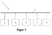
- the FIG. 1 schematically shows a device 1 for generating a virtual target for sharp shots training.
- the device 1 comprises a device 2 for generating a non-solid projection surface, a control device 3, a projection system 4 and a detector 5 for determining the position of the weft passage of a projectile through the projection surface.
- the device 2 is a spray device for a liquid or aerosol mist.
- the control device 3 controls the components of the device 1, ie the device 2 for generating the non-solid projection surface, the projection system 4 and the query of the detector 5. It also contains an image generator for generating a target data set representing a target.
- the image generator is preferably designed as a computer program that is executed in the control device 3.
- the image generator generates a static or time varying image of a target, which image is represented by the target data set and transmitted to the projection system 4.
- image thus includes both a static frame, for example in the form of a photo, as well as a sequence of images, so a video.
- the control device 3 controls the hit display for triggering an acoustic, optical or pyrotechnic hit display.
- the projection system is a video projector which projects the image generated by the image generator two-dimensionally onto the projection surface.
- the projected image represents a virtual target.
- the image generator can reproduce a stored image and transmit it to the projection system 4 or dynamically generate the image.
- the image generator may, for example, select and reproduce one of several stored images.
- the image generator can calculate a synthetic image as a function of the exercise scenario, for example based on predetermined shapes and textures.
- the properties of the virtual target are particularly variable through the use of the present invention.
- the image generator is configured to vary the type of target (person, vehicle, building, etc.), size, location, and / or surface texture.
- the image generator may vary the image to reflect influences such as the lighting situation of the target (eg, day or night), visibility (e.g., fog or rain), or Visibility (for example, obscuring other objects).
- the detector 5 for determining the position of the weft passage of a projectile through the projection surface is a Location Of Miss And Hits (LOMAH) system.
- LOMAH systems designed for supersonic projectiles have a plurality of acoustic sensors which sense the projectile generated supersonic funnel and calculate the position of the projectile relative to the detector 5 from the transit time differences.
- the relative positions between the device 2 for generating the non-solid projection surface, and thus the projection surface, the projection system 4 and the detector 5 are known. If these relative positions in the detector 5 are known, then this can calculate the position of the weft passage of the projectile through the projection surface and transmit it to the control device 3. Alternatively, the detector 5 transmits data about the trajectory of the projectile, relative to the detector 5, to the control device 3, which calculates therefrom and from the relative positions the position of the weft passage of the projectile through the projection surface. A calculated hit can optionally be displayed by the hit display 6.
- control device 3 is connected via a bus system 7 with the other components of the device 1.
- one or more of the components may also be connected to the control device 3 in each case via a dedicated control line.
Landscapes
- Engineering & Computer Science (AREA)
- General Engineering & Computer Science (AREA)
- Physics & Mathematics (AREA)
- Acoustics & Sound (AREA)
- Aiming, Guidance, Guns With A Light Source, Armor, Camouflage, And Targets (AREA)
Description
- Zum Training des Umgangs mit einer Schusswaffe ist es unerlässlich, mit scharfer Munition zu trainieren, bei der ein Projektil abgefeuert wird. Dies wird als scharfes Schusstraining bezeichnet. Auf einem Schießstand wird üblicherweise auf kreisrunde Zielscheiben geschossen. Realistischere Szenarien werden geschaffen, indem Objekten nachempfundene Zielscheiben verwendet werden, die nur für eine gewisse Zeit und nicht dauerhaft sichtbar sind. Dazu werden die Zielscheiben beispielsweise geklappt oder verschwenkt.
- Die
DE 10 2006 021 114 A1 bildet die Grundlage für den Oberbegriff des Anspruches 1. Die vorliegende Erfindung betrifft eine Vorrichtung nach dem Anspruch 1. - Die nicht-feste Projektionsfläche ist gestaltlos. Sie besteht beispielsweise aus Nebel (zum Beispiel in Form einer Nebelwand) oder Flüssigkeit, insbesondere zerstäubten Flüssigkeitstropfen. Dadurch, dass die Projektionsfläche nicht-fest ist, weist sie keine Struktur auf, die von dem Projektil zerstört werden könnte. Die Projektionsfläche ist kein Festkörper, kann also auch als Nicht-Festkörper bezeichnet werden. Sie kann auch als virtuelle Projektionsfläche bezeichnet werden. Der Begriff "Projektionsfläche" umfasst auch dreidimensionale Bereiche, in die ein dreidimensionales Bild projiziert wird.
- Die Einrichtung zur Erzeugung der nicht-festen Projektionsfläche ist erfindungsgemäß eine Sprühvorrichtung für einen Flüssigkeits- oder Aerosolnebel. Flüssigkeitsnebel besteht beispielsweise aus feinen, zerstäubten Flüssigkeitströpfchen. Aerosolnebel besteht aus flüssigen oder festen Schwebeteilchen in Verbindung mit einem Gas.
- Die Einrichtung zur Erzeugung der nicht-festen Projektionsfläche weist insbesondere Düsen auf, die den Stoff abgeben, der die Projektionsfläche bildet. Die Düsen sind bevorzugt so angeordnet, dass sie von der Position des Bedieners der Schusswaffe aus nicht sichtbar sind. Alternativ oder zusätzlich sind die Düsen so angeordnet, dass die erzeugte Projektionsfläche windunempfindlich ist.
- Optional ist die Einrichtung zur Erzeugung einer nicht-festen Projektionsfläche dazu eingerichtet, dem versprühten Stoff einen Hilfsstoff wie einen Farbstoff oder Streupartikel beizumischen. Dadurch können die Reflektionseigenschaften der Projektionsfläche verändert werden. Alternativ oder zusätzlich können die Auswirkungen von Umwelteinflüssen, wie beispielsweise die Helligkeit des Umgebungslichts oder Wind, auf die Projektion minimiert werden. Optional ist der Hilfsstoff dem versprühten Stoff bereits beigemischt.
- Optional ist die Einrichtung zur Erzeugung einer nicht-festen Projektionsfläche dazu eingerichtet, die Projektionsfläche intermittierend zu erzeugen. Dies bedeutet, dass die Projektionsfläche nicht kontinuierlich erzeugt wird, sondern sporadisch oder regelmäßig ausgesetzt wird. Somit können beispielsweise Windeinflüsse auf die erzeugte Projektionsfläche minimiert werden. Weiterhin ist dadurch die Funktionalität einer Klappscheibe sofort realisierbar.
- Der Bildgenerator erzeugt einen Zieldatensatz, der ein Ziel repräsentiert. Der Zieldatensatz ist insbesondere ein Bilddatensatz. Dieser repräsentiert ein zweidimensionales oder dreidimensionales Bild des Ziels. Das Bild des Ziels ist bevorzugt mit der Zeit veränderlich, also dynamisch. Das Bild kann ein aufgezeichnetes Bild sein, ein im Vorfeld berechnetes Bild oder ein in Echtzeit berechnetes Bild. Ein in Echtzeit berechnetes Bild hat den Vorteil, dass das Ziel besonders flexibel situationsabhängig erzeugt werden kann, beispielsweise in Abhängigkeit vom Verlauf des Schusstrainings. Der Datensatz kann im Rahmen dieses Dokuments auch ein Datenstrom sein.
- Der Zieldatensatz wird an das Projektionssystem übertragen, das das Ziel auf die Projektionsfläche projiziert. Bei dem Projektionssystem handelt es sich beispielsweise um einen Videoprojektor, zum Beispiel einen Röhrenprojektor, einen LCD-Projektor, einen DLP-Projektor, einen LED-Projektor, einen LCoS-Projektor (Liquid Crystal on Silicon) oder einen Laserprojektor. Optional ist das Projektionssystem dazu eingerichtet, ein dreidimensionales Bild des Ziels zu projizieren. Das projizierte Ziel wird als virtuelles Ziel bezeichnet.
- Ein Vorteil des virtuellen Ziels gegenüber herkömmlichen Zielscheiben liegt darin, dass die Gestalt des virtuellen Ziels variabel ist. Insbesondere ist der Bildgenerator dazu eingerichtet, mindestens eines aus der Art, der Form, der Größe, der Lage, der Oberfläche, der Ausleuchtung und der Sichtbarkeit des Ziels zu variieren. Mögliche Arten des Ziels sind unter anderem Personen, Fahrzeuge, Gebäude oder sonstige Gegenstände. Die Ausleuchtung und die Sichtbarkeit repräsentieren Einflüsse wie beispielsweise die Helligkeit und/oder die spektrale Zusammensetzung der Beleuchtung des Ziels oder Sichtbehinderungen wie Nebel, Regen oder Gegenstände, die das Ziel zumindest teilweise verdecken.
- Ein weiterer Vorteil der erfindungsgemäßen Vorrichtung liegt darin, dass keine Mechanik notwendig ist, um die Position einer Zielscheibe zu verändern, da die Sichtbarkeit des Ziels über den Bildgenerator und/oder die Einrichtung zur Erzeugung der nicht-festen Projektionsfläche eingestellt wird. Soll das Ziel sichtbar sein, wird im letzteren Fall die Einrichtung eingeschaltet, soll das Ziel unsichtbar sein, wird sie abgeschaltet.
- Darüber hinaus werden herkömmliche Zielscheiben durch wiederholte Treffer im Laufe der Zeit so beschädigt, dass sie ausgetauscht werden müssen. Da die Projektionsfläche der vorliegenden Erfindung kein Festkörper ist, entsteht durch ein Projektil kein Schaden an der Struktur des Ziels.
- Der Detektor zur Ermittlung der Position des Schussdurchgangs eines Projektils durch die Projektionsfläche dient der Ermittlung, ob das Projektil das virtuelle Ziel getroffen hat oder nicht. Der Detektor ist in der Nähe der Projektionsfläche angeordnet, bevorzugt zwischen der Projektionsfläche und der Position der Schusswaffe. Optional ist der Erfassungsbereich des Detektors so groß, dass festgestellt werden kann, wo und in welchem Abstand das Projektil das virtuelle Ziel verfehlt hat. Der Detektor weist mindestens einen Sensor auf, zum Beispiel einen akustischen oder optischen Sensor.
- Der Detektor zur Ermittlung der Position des Schussdurchgangs ist bevorzugt ein LOMAH-System (Location Of Miss And Hits). Derartige Systeme sind von verschiedenen Herstellern erhältlich. Alternativ detektiert der Detektor zur Ermittlung der Position des Schussdurchgangs den Schussdurchgang optisch. Dazu weist der Detektor beispielsweise eine Videokamera, insbesondere mit 3D-Time-of-Flight-Bildsensoren als Zeilen- oder Flächenkamera, auf, die die Projektionsfläche erfasst und aus deren Ausgangssignal die Position des Schussdurchgangs ermittelt wird. Eine weitere Möglichkeit der optischen Ermittlung besteht darin, einen Bereich mit einem oder mehreren, beispielsweise zwei oder mehr, Lasern auszuleuchten und den Schussdurchgang nach Triangulationsverfahren zu lokalisieren, indem beispielsweise das durch das Projektil gestreute Licht mit einem ortsauflösenden Detektor, beispielsweise einer Kamera, detektiert wird, oder beispielsweise durch sehr schnelle fächerartige Ablenkung der Laserstrahlen, wobei die Fächer in einer gemeinsamen Ebene zwischen der Projektionsfläche und der Position der Schusswaffe angeordnet sind, die Schussposition gemessen wird, indem. der Laserstrahl von dem Projektil gestreut oder reflektiert und ermittelt wird, in welche Richtung der Laserstrahl in diesem Zeitpunkt abgelenkt wurde. Ist diese Information für zwei Laser bekannt, so ergibt sich die Position des Schussdurchgangs aus dem Schnittpunkt der beiden Laserstrahlen.
- Optional weist die erfindungsgemäße Vorrichtung eine Trefferanzeige auf, die dazu eingerichtet ist, ein akustisches Hinweissignal, beispielsweise über einen Lautsprecher, oder ein visuelles Hinweissignal, beispielsweise mit Hilfe einer Rundumleuchte, oder ein pyrotechnisches Hinweissignal, beispielsweise mit einer Blitz-/Knallpatrone, auszugeben, wenn das Projektil das virtuelle Ziel getroffen hat. Alternativ oder zusätzlich verändert der Bildgenerator den Zieldatensatz derart, dass ein Treffer signalisiert wird.
- Bevorzugt weist die Vorrichtung eine Steuereinrichtung auf, die die Komponenten der Vorrichtung steuert. Dazu ist die Steuereinrichtung mit den Komponenten verbunden, beispielsweise über einen gemeinsamen Datenbus, eine dedizierte Steuerleitung zwischen der Steuereinrichtung und einer Komponente oder eine Kombination daraus. Der Bildgenerator ist bevorzugt Bestandteil der Steuereinrichtung. Der Detektor zur Ermittlung der Position des Schussdurchgangs berechnet beispielsweise die Position des Schussdurchgangs und übermittelt diese an die Steuereinrichtung. Alterativ übermittelt der Detektor Sensorausgangssignale an die Steuereinrichtung, die daraus die Position des Schussdurchgangs berechnet.
- Es liegt im Rahmen der vorliegenden Erfindung, einzelne Merkmale aus Ausführungsformen oder Ausgestaltungsformen oder optionale Merkmale miteinander zu kombinieren oder nicht erfindungswesentliche Merkmale einer Ausführungsform oder Ausgestaltungsform wegzulassen.
- Die vorliegende Erfindung soll anhand eines Ausführungsbeispiels näher erläutert werden. Dabei zeigt:
- Figur 1
- eine schematische Darstellung einer erfindungsgemäßen Vorrichtung.
- Die
Figur 1 zeigt schematisch eine Vorrichtung 1 zur Erzeugung eines virtuellen Ziels für scharfes Schusstraining. Die Vorrichtung 1 umfasst eine Einrichtung 2 zur Erzeugung einer nicht-festen Projektionsfläche, eine Steuereinrichtung 3, ein Projektionssystem 4 und einen Detektor 5 zur Ermittlung der Position des Schussdurchgangs eines Projektils durch die Projektionsfläche. - Bei der Einrichtung 2 handelt es sich um eine Sprühvorrichtung für einen Flüssigkeits- oder Aerosolnebel.
- Die Steuereinrichtung 3 steuert die Komponenten der Vorrichtung 1, also die Einrichtung 2 zur Erzeugung der nicht-festen Projektionsfläche, das Projektionssystem 4 und die Abfrage des Detektors 5. Sie enthält weiterhin einen Bildgenerator zur Erzeugung eines Zieldatensatzes, der ein Ziel repräsentiert. Der Bildgenerator ist bevorzugt als Computerprogramm ausgebildet, das in der Steuereinrichtung 3 ausgeführt wird. Der Bildgenerator erzeugt ein statisches oder mit der Zeit veränderliches Bild von einem Ziel, wobei dieses Bild von dem Zieldatensatz repräsentiert und an das Projektionssystem 4 übertragen wird. Der Begriff "Bild" umfasst also sowohl ein statisches Einzelbild, beispielsweise in Form eines Fotos, als auch eine Sequenz von Bildern, also ein Video. Optional steuert die Steuereinrichtung 3 die Trefferanzeige zur Auslösung einer akustischen, optischen oder pyrotechnischen Trefferanzeige.
- Das Projektionssystem ist im vorliegenden Ausführungsbeispiel ein Videoprojektor, der das vom Bildgenerator erzeugt Bild zweidimensional auf die Projektionsfläche projiziert. Das projizierte Bild stellt ein virtuelles Ziel dar. Der Bildgenerator kann ein abgespeichertes Bild reproduzieren und an das Projektionssystem 4 übertragen oder das Bild dynamisch generieren. Im ersten Fall kann der Bildgenerator in Abhängigkeit vom Übungsszenario beispielsweise eines von mehreren gespeicherten Bildern auswählen und reproduzieren. Im zweiten Fall kann der Bildgenerator ein, synthetisches Bild in Abhängigkeit vom Übungsszenario berechnen, beispielsweise anhand von vorgegebenen Formen und Texturen.
- Die Eigenschaften des virtuellen Ziels sind durch die Verwendung der vorliegenden Erfindung besonders variabel. Der Bildgenerator ist dazu eingerichtet, die Art des Ziels (Person, Fahrzeug, Gebäude, etc.), die Größe, die Lage und/oder die Oberflächenstruktur zu variieren.
- Unabhängig davon, ob es sich bei dem Bild um ein gespeichertes oder berechnetes Bild handelt, kann der Bildgenerator das Bild variieren, um Einflüsse wie die Beleuchtungssituation des Ziels (zum Beispiel Tag oder Nacht), die Sichtverhältnisse (zum Beispiel Nebel oder Regen) oder die Sichtbarkeit (zum Beispiel eine Verdeckung durch andere Objekte) zu simulieren.
- Im vorliegenden Ausführungsbeispiel ist der Detektor 5 zur Ermittlung der Position des Schussdurchgangs eines Projektils durch die Projektionsfläche ein LOMAH-System (Location Of Miss And Hits). Derartige Systeme sind von verschiedenen Herstellern erhältlich. Für überschallschnelle Projektile ausgelegte LOMAH-Systeme weisen mehrere akustische Sensoren auf, die den vom Projektil erzeugten Überschalltrichter sensieren und aus den Laufzeitunterschieden die Position des Projektils relativ zum Detektor 5 berechnen.
- Die Relativpositionen zwischen der Einrichtung 2 zur Erzeugung der nicht-festen Projektionsfläche, und damit der Projektionsfläche, dem Projektionssystem 4 und dem Detektor 5 sind bekannt. Sind diese Relativpositionen im Detektor 5 bekannt, so kann dieser die Position des Schussdurchgangs des Projektils durch die Projektionsfläche berechnen und an die Steuereinrichtung 3 übermitteln. Alternativ übermittelt der Detektor 5 Daten über die Trajektorie des Projektils, bezogen auf den Detektor 5, an die Steuereinrichtung 3, die daraus und aus den Relativpositionen die Position des Schussdurchgangs des Projektils durch die Projektionsfläche berechnet. Ein berechneter Treffer kann optional durch die Trefferanzeige 6 angezeigt werden.
- Im vorliegenden Ausführungsbeispiel ist die Steuereinrichtung 3 über ein BUS-System 7 mit den anderen Komponenten der Vorrichtung 1 verbunden. Eine oder mehrere der Komponenten können jedoch auch jeweils über eine dedizierte Steuerleitung mit der Steuereinrichtung 3 verbunden sein.
Claims (7)
- Vorrichtung (1) zur Erzeugung eines virtuellen Ziels für scharfes Schusstraining, aufweisend eine Einrichtung (2) zur Erzeugung einer nicht-festen Projektionsfläche, einen Bildgenerator (3) zur Erzeugung eines Zieldatensatzes, der ein Ziel repräsentiert, ein Projektionssystem (4) zur Projektion des Ziels auf die Projektionsfläche und einen Detektor (5) zur Ermittlung der Position des Schussdurchgangs eines Projektils durch die Projektionsfläche dadurch gekennzeichnet, dass die Einrichtung (2) zur Erzeugung einer nicht-festen Projektionsfläche eine Sprühvorrichtung für einen Flüssigkeits- oder Aerosolnebel ist.
- Vorrichtung (1) nach Anspruch 1, dadurch gekennzeichnet, dass der Detektor (5) zur Ermittlung der Position des Schussdurchgangs ein LOMAH-System (Location Of Miss And Hits) ist.
- Vorrichtung (1) nach Anspruch 1, dadurch gekennzeichnet, dass der Detektor (5) zur Ermittlung der Position des Schussdurchgangs den Schussdurchgang optisch detektiert.
- Vorrichtung (1) nach einem der Ansprüche 1 bis 3, dadurch gekennzeichnet, dass der Bildgenerator (3) dazu eingerichtet ist, mindestens eines aus der Art, der Form, der Größe, der Lage, der Oberfläche, der Ausleuchtung und der Sichtbarkeit des Ziels zu variieren.
- Vorrichtung (1) nach einem der Ansprüche 1 bis 4, gekennzeichnet durch einen Lautsprecher, der dazu eingerichtet ist, ein akustisches, optisches oder pyrotechnisches Hinweissignal auszugeben, wenn das Projektil das virtuelle Ziel getroffen hat.
- Vorrichtung (1) nach Anspruch 1, dadurch gekennzeichnet, dass die Einrichtung (2) zur Erzeugung einer nicht-festen Projektionsfläche dazu eingerichtet ist, dem versprühten Stoff einen Hilfsstoff wie einen Farbstoff oder Streupartikel beizumischen.
- Vorrichtung (1) nach einem der Ansprüche 1 bis 6, dadurch gekennzeichnet, dass die Einrichtung (2) zur Erzeugung einer nicht-festen Projektionsfläche dazu eingerichtet ist, die Projektionsfläche intermittierend zu erzeugen.
Applications Claiming Priority (2)
| Application Number | Priority Date | Filing Date | Title |
|---|---|---|---|
| DE201110014745 DE102011014745A1 (de) | 2011-03-22 | 2011-03-22 | Vorrichtung zur Erzeugung eines virtuellen Ziels für scharfes Schusstraining |
| PCT/EP2012/052927 WO2012126690A1 (de) | 2011-03-22 | 2012-02-21 | Vorrichtung zur erzeugung eines virtuellen ziels für scharfes schusstraining |
Publications (2)
| Publication Number | Publication Date |
|---|---|
| EP2689210A1 EP2689210A1 (de) | 2014-01-29 |
| EP2689210B1 true EP2689210B1 (de) | 2015-04-01 |
Family
ID=45755345
Family Applications (1)
| Application Number | Title | Priority Date | Filing Date |
|---|---|---|---|
| EP12705292.6A Not-in-force EP2689210B1 (de) | 2011-03-22 | 2012-02-21 | Vorrichtung zur erzeugung eines virtuellen ziels für scharfes schusstraining |
Country Status (4)
| Country | Link |
|---|---|
| EP (1) | EP2689210B1 (de) |
| DE (1) | DE102011014745A1 (de) |
| RU (1) | RU2013146221A (de) |
| WO (1) | WO2012126690A1 (de) |
Families Citing this family (3)
| Publication number | Priority date | Publication date | Assignee | Title |
|---|---|---|---|---|
| RU2638510C1 (ru) * | 2016-12-01 | 2017-12-13 | Федеральное казенное предприятие "Научно-исследовательский институт "Геодезия" (ФКП "НИИ "Геодезия") | Способ формирования атмосферной проекционной мишени для обучения боевой стрельбе и устройство для его осуществления |
| DE102019000573B4 (de) | 2019-01-26 | 2025-02-20 | Bundesrepublik Deutschland, vertreten durch das Bundesministerium der Verteidigung, vertreten durch das Bundesamt für Ausrüstung, Informationstechnik und Nutzung der Bundeswehr | Ortsunabhängige Zieldarstellung |
| US11719503B2 (en) | 2020-01-24 | 2023-08-08 | Innovative Services And Solutions Llc | Firearm training system and method utilizing distributed stimulus projection |
Family Cites Families (4)
| Publication number | Priority date | Publication date | Assignee | Title |
|---|---|---|---|---|
| FR578355A (fr) * | 1923-05-17 | 1924-09-24 | But mobile pour tir | |
| US3475029A (en) * | 1967-01-20 | 1969-10-28 | Us Navy | Non-material aiming target |
| US7872211B2 (en) * | 2005-06-10 | 2011-01-18 | Igor Troitski | Laser-dynamic system for using in games |
| DE102006021114A1 (de) * | 2006-05-04 | 2007-11-08 | Groß, Hansjörg | Projektionseinheit einer Raumschießanlage |
-
2011
- 2011-03-22 DE DE201110014745 patent/DE102011014745A1/de not_active Withdrawn
-
2012
- 2012-02-21 EP EP12705292.6A patent/EP2689210B1/de not_active Not-in-force
- 2012-02-21 RU RU2013146221/28A patent/RU2013146221A/ru unknown
- 2012-02-21 WO PCT/EP2012/052927 patent/WO2012126690A1/de not_active Ceased
Also Published As
| Publication number | Publication date |
|---|---|
| RU2013146221A (ru) | 2015-04-27 |
| WO2012126690A1 (de) | 2012-09-27 |
| EP2689210A1 (de) | 2014-01-29 |
| DE102011014745A1 (de) | 2012-09-27 |
Similar Documents
| Publication | Publication Date | Title |
|---|---|---|
| DE2846962C2 (de) | Laserlicht-Schußsimulator für Lenkflugkörper | |
| DE102013003448A1 (de) | Vorrichtung und Verfahren zum Testen von Fahrerassistenzsystemen | |
| DE112016000274T5 (de) | System zum Generieren virtueller Radarsignaturen | |
| DE102017107396A1 (de) | Testverfahren und Testvorrichtung für Fahrerassistenzsysteme | |
| EP4121795B1 (de) | Test-system zum testen einer lidar-vorrichtung | |
| DE102007014878A1 (de) | Verfahren zur Rundum-Kollisionswarnung für Hubschrauber | |
| DE102015007028A1 (de) | Verfahren zur Fokussierung eines hochenergetischen Strahls auf einem Haltepunkt auf der Oberfläche eines fliegenden Flugobjekts | |
| DE3623083A1 (de) | Vorrichtung zur schusssimulation | |
| DE102011119480B4 (de) | Verfahren und Vorrichtung zur Verfolgung eines bewegten Zielobjekts | |
| CH669660A5 (de) | ||
| EP2689210A1 (de) | Vorrichtung zur erzeugung eines virtuellen ziels für scharfes schusstraining | |
| DE3705142A1 (de) | Einrichtung zur selbsttaetigen elektronischen messung und anzeige der trefferablagen von geschossen, wurfkoerpern, flugkoerpern u. dgl. | |
| DE102011109460A1 (de) | Warnanlage für Kraftfahrzeuge | |
| DE1951622C3 (de) | Anordnung zur simulierten Darstellung von Schußbahnen | |
| DE2658501B2 (de) | Verfahren zur Simulation eines beweglichen Zieles | |
| DE102018211943A1 (de) | Radarsystem zur Kollisionsvermeidung eines Roboters | |
| DE19638968A1 (de) | Verfahren und Vorrichtung zur Bekämpfung anfliegender Flugkörper | |
| DE3028545C2 (de) | Verfahren zur Schußsimulation bei beweglichen Zielen mittels Lichtsignalen | |
| EP3348953B1 (de) | Vorrichtung zum ermitteln der treffsicherheit eines schützen | |
| DE2429006B2 (de) | Verfahren zur Schußsimulation ferngelenkter Flugkörper und Vorrichtung zur Durchführung des Verfahrens | |
| EP0154809A1 (de) | Verfahren zur Gefechtssimulation | |
| EP3278050B1 (de) | System zur justierung der sichtachsen eines gefechtsfahrzeugs sowie verfahren dazu | |
| DE102013015324A1 (de) | Vorrichtung sowie Verfahren | |
| EP3762915B1 (de) | Technische umrüstung von schusswaffen zur umsetzung von mr und ar interaktion | |
| WO1992018824A1 (de) | Verfahren und vorrichtung zur darstellung von trefferablagen im schützenvisier |
Legal Events
| Date | Code | Title | Description |
|---|---|---|---|
| PUAI | Public reference made under article 153(3) epc to a published international application that has entered the european phase |
Free format text: ORIGINAL CODE: 0009012 |
|
| 17P | Request for examination filed |
Effective date: 20130904 |
|
| AK | Designated contracting states |
Kind code of ref document: A1 Designated state(s): AL AT BE BG CH CY CZ DE DK EE ES FI FR GB GR HR HU IE IS IT LI LT LU LV MC MK MT NL NO PL PT RO RS SE SI SK SM TR |
|
| DAX | Request for extension of the european patent (deleted) | ||
| GRAP | Despatch of communication of intention to grant a patent |
Free format text: ORIGINAL CODE: EPIDOSNIGR1 |
|
| INTG | Intention to grant announced |
Effective date: 20141020 |
|
| GRAS | Grant fee paid |
Free format text: ORIGINAL CODE: EPIDOSNIGR3 |
|
| GRAA | (expected) grant |
Free format text: ORIGINAL CODE: 0009210 |
|
| AK | Designated contracting states |
Kind code of ref document: B1 Designated state(s): AL AT BE BG CH CY CZ DE DK EE ES FI FR GB GR HR HU IE IS IT LI LT LU LV MC MK MT NL NO PL PT RO RS SE SI SK SM TR |
|
| REG | Reference to a national code |
Ref country code: GB Ref legal event code: FG4D Free format text: NOT ENGLISH |
|
| REG | Reference to a national code |
Ref country code: CH Ref legal event code: EP |
|
| REG | Reference to a national code |
Ref country code: IE Ref legal event code: FG4D Free format text: LANGUAGE OF EP DOCUMENT: GERMAN |
|
| REG | Reference to a national code |
Ref country code: DE Ref legal event code: R096 Ref document number: 502012002697 Country of ref document: DE Effective date: 20150513 |
|
| REG | Reference to a national code |
Ref country code: AT Ref legal event code: REF Ref document number: 719323 Country of ref document: AT Kind code of ref document: T Effective date: 20150515 |
|
| REG | Reference to a national code |
Ref country code: CH Ref legal event code: NV Representative=s name: E. BLUM AND CO. AG PATENT- UND MARKENANWAELTE , CH |
|
| REG | Reference to a national code |
Ref country code: NL Ref legal event code: VDEP Effective date: 20150401 |
|
| REG | Reference to a national code |
Ref country code: LT Ref legal event code: MG4D |
|
| PG25 | Lapsed in a contracting state [announced via postgrant information from national office to epo] |
Ref country code: NL Free format text: LAPSE BECAUSE OF FAILURE TO SUBMIT A TRANSLATION OF THE DESCRIPTION OR TO PAY THE FEE WITHIN THE PRESCRIBED TIME-LIMIT Effective date: 20150401 |
|
| PG25 | Lapsed in a contracting state [announced via postgrant information from national office to epo] |
Ref country code: ES Free format text: LAPSE BECAUSE OF FAILURE TO SUBMIT A TRANSLATION OF THE DESCRIPTION OR TO PAY THE FEE WITHIN THE PRESCRIBED TIME-LIMIT Effective date: 20150401 Ref country code: PT Free format text: LAPSE BECAUSE OF FAILURE TO SUBMIT A TRANSLATION OF THE DESCRIPTION OR TO PAY THE FEE WITHIN THE PRESCRIBED TIME-LIMIT Effective date: 20150803 Ref country code: NO Free format text: LAPSE BECAUSE OF FAILURE TO SUBMIT A TRANSLATION OF THE DESCRIPTION OR TO PAY THE FEE WITHIN THE PRESCRIBED TIME-LIMIT Effective date: 20150701 Ref country code: LT Free format text: LAPSE BECAUSE OF FAILURE TO SUBMIT A TRANSLATION OF THE DESCRIPTION OR TO PAY THE FEE WITHIN THE PRESCRIBED TIME-LIMIT Effective date: 20150401 Ref country code: HR Free format text: LAPSE BECAUSE OF FAILURE TO SUBMIT A TRANSLATION OF THE DESCRIPTION OR TO PAY THE FEE WITHIN THE PRESCRIBED TIME-LIMIT Effective date: 20150401 Ref country code: FI Free format text: LAPSE BECAUSE OF FAILURE TO SUBMIT A TRANSLATION OF THE DESCRIPTION OR TO PAY THE FEE WITHIN THE PRESCRIBED TIME-LIMIT Effective date: 20150401 Ref country code: CZ Free format text: LAPSE BECAUSE OF FAILURE TO SUBMIT A TRANSLATION OF THE DESCRIPTION OR TO PAY THE FEE WITHIN THE PRESCRIBED TIME-LIMIT Effective date: 20150401 |
|
| PG25 | Lapsed in a contracting state [announced via postgrant information from national office to epo] |
Ref country code: GR Free format text: LAPSE BECAUSE OF FAILURE TO SUBMIT A TRANSLATION OF THE DESCRIPTION OR TO PAY THE FEE WITHIN THE PRESCRIBED TIME-LIMIT Effective date: 20150702 Ref country code: RS Free format text: LAPSE BECAUSE OF FAILURE TO SUBMIT A TRANSLATION OF THE DESCRIPTION OR TO PAY THE FEE WITHIN THE PRESCRIBED TIME-LIMIT Effective date: 20150401 Ref country code: LV Free format text: LAPSE BECAUSE OF FAILURE TO SUBMIT A TRANSLATION OF THE DESCRIPTION OR TO PAY THE FEE WITHIN THE PRESCRIBED TIME-LIMIT Effective date: 20150401 Ref country code: IS Free format text: LAPSE BECAUSE OF FAILURE TO SUBMIT A TRANSLATION OF THE DESCRIPTION OR TO PAY THE FEE WITHIN THE PRESCRIBED TIME-LIMIT Effective date: 20150801 |
|
| REG | Reference to a national code |
Ref country code: DE Ref legal event code: R097 Ref document number: 502012002697 Country of ref document: DE |
|
| PG25 | Lapsed in a contracting state [announced via postgrant information from national office to epo] |
Ref country code: DK Free format text: LAPSE BECAUSE OF FAILURE TO SUBMIT A TRANSLATION OF THE DESCRIPTION OR TO PAY THE FEE WITHIN THE PRESCRIBED TIME-LIMIT Effective date: 20150401 Ref country code: EE Free format text: LAPSE BECAUSE OF FAILURE TO SUBMIT A TRANSLATION OF THE DESCRIPTION OR TO PAY THE FEE WITHIN THE PRESCRIBED TIME-LIMIT Effective date: 20150401 |
|
| PLBE | No opposition filed within time limit |
Free format text: ORIGINAL CODE: 0009261 |
|
| STAA | Information on the status of an ep patent application or granted ep patent |
Free format text: STATUS: NO OPPOSITION FILED WITHIN TIME LIMIT |
|
| REG | Reference to a national code |
Ref country code: FR Ref legal event code: PLFP Year of fee payment: 5 |
|
| PG25 | Lapsed in a contracting state [announced via postgrant information from national office to epo] |
Ref country code: PL Free format text: LAPSE BECAUSE OF FAILURE TO SUBMIT A TRANSLATION OF THE DESCRIPTION OR TO PAY THE FEE WITHIN THE PRESCRIBED TIME-LIMIT Effective date: 20150401 Ref country code: RO Free format text: LAPSE BECAUSE OF NON-PAYMENT OF DUE FEES Effective date: 20150401 Ref country code: SK Free format text: LAPSE BECAUSE OF FAILURE TO SUBMIT A TRANSLATION OF THE DESCRIPTION OR TO PAY THE FEE WITHIN THE PRESCRIBED TIME-LIMIT Effective date: 20150401 |
|
| 26N | No opposition filed |
Effective date: 20160105 |
|
| PG25 | Lapsed in a contracting state [announced via postgrant information from national office to epo] |
Ref country code: IT Free format text: LAPSE BECAUSE OF FAILURE TO SUBMIT A TRANSLATION OF THE DESCRIPTION OR TO PAY THE FEE WITHIN THE PRESCRIBED TIME-LIMIT Effective date: 20150401 |
|
| PG25 | Lapsed in a contracting state [announced via postgrant information from national office to epo] |
Ref country code: SI Free format text: LAPSE BECAUSE OF FAILURE TO SUBMIT A TRANSLATION OF THE DESCRIPTION OR TO PAY THE FEE WITHIN THE PRESCRIBED TIME-LIMIT Effective date: 20150401 Ref country code: BE Free format text: LAPSE BECAUSE OF NON-PAYMENT OF DUE FEES Effective date: 20160229 |
|
| PG25 | Lapsed in a contracting state [announced via postgrant information from national office to epo] |
Ref country code: LU Free format text: LAPSE BECAUSE OF FAILURE TO SUBMIT A TRANSLATION OF THE DESCRIPTION OR TO PAY THE FEE WITHIN THE PRESCRIBED TIME-LIMIT Effective date: 20160221 Ref country code: MC Free format text: LAPSE BECAUSE OF FAILURE TO SUBMIT A TRANSLATION OF THE DESCRIPTION OR TO PAY THE FEE WITHIN THE PRESCRIBED TIME-LIMIT Effective date: 20150401 |
|
| REG | Reference to a national code |
Ref country code: IE Ref legal event code: MM4A |
|
| PG25 | Lapsed in a contracting state [announced via postgrant information from national office to epo] |
Ref country code: IE Free format text: LAPSE BECAUSE OF NON-PAYMENT OF DUE FEES Effective date: 20160221 |
|
| REG | Reference to a national code |
Ref country code: FR Ref legal event code: PLFP Year of fee payment: 6 |
|
| PG25 | Lapsed in a contracting state [announced via postgrant information from national office to epo] |
Ref country code: SE Free format text: LAPSE BECAUSE OF FAILURE TO SUBMIT A TRANSLATION OF THE DESCRIPTION OR TO PAY THE FEE WITHIN THE PRESCRIBED TIME-LIMIT Effective date: 20150401 |
|
| PG25 | Lapsed in a contracting state [announced via postgrant information from national office to epo] |
Ref country code: MT Free format text: LAPSE BECAUSE OF FAILURE TO SUBMIT A TRANSLATION OF THE DESCRIPTION OR TO PAY THE FEE WITHIN THE PRESCRIBED TIME-LIMIT Effective date: 20150401 |
|
| REG | Reference to a national code |
Ref country code: FR Ref legal event code: PLFP Year of fee payment: 7 |
|
| REG | Reference to a national code |
Ref country code: AT Ref legal event code: MM01 Ref document number: 719323 Country of ref document: AT Kind code of ref document: T Effective date: 20170221 |
|
| PG25 | Lapsed in a contracting state [announced via postgrant information from national office to epo] |
Ref country code: AT Free format text: LAPSE BECAUSE OF NON-PAYMENT OF DUE FEES Effective date: 20170221 Ref country code: CY Free format text: LAPSE BECAUSE OF FAILURE TO SUBMIT A TRANSLATION OF THE DESCRIPTION OR TO PAY THE FEE WITHIN THE PRESCRIBED TIME-LIMIT Effective date: 20150401 Ref country code: SM Free format text: LAPSE BECAUSE OF FAILURE TO SUBMIT A TRANSLATION OF THE DESCRIPTION OR TO PAY THE FEE WITHIN THE PRESCRIBED TIME-LIMIT Effective date: 20150401 Ref country code: HU Free format text: LAPSE BECAUSE OF FAILURE TO SUBMIT A TRANSLATION OF THE DESCRIPTION OR TO PAY THE FEE WITHIN THE PRESCRIBED TIME-LIMIT; INVALID AB INITIO Effective date: 20120221 |
|
| PG25 | Lapsed in a contracting state [announced via postgrant information from national office to epo] |
Ref country code: MK Free format text: LAPSE BECAUSE OF FAILURE TO SUBMIT A TRANSLATION OF THE DESCRIPTION OR TO PAY THE FEE WITHIN THE PRESCRIBED TIME-LIMIT Effective date: 20150401 Ref country code: TR Free format text: LAPSE BECAUSE OF FAILURE TO SUBMIT A TRANSLATION OF THE DESCRIPTION OR TO PAY THE FEE WITHIN THE PRESCRIBED TIME-LIMIT Effective date: 20150401 |
|
| PG25 | Lapsed in a contracting state [announced via postgrant information from national office to epo] |
Ref country code: BG Free format text: LAPSE BECAUSE OF FAILURE TO SUBMIT A TRANSLATION OF THE DESCRIPTION OR TO PAY THE FEE WITHIN THE PRESCRIBED TIME-LIMIT Effective date: 20150401 |
|
| PG25 | Lapsed in a contracting state [announced via postgrant information from national office to epo] |
Ref country code: AL Free format text: LAPSE BECAUSE OF FAILURE TO SUBMIT A TRANSLATION OF THE DESCRIPTION OR TO PAY THE FEE WITHIN THE PRESCRIBED TIME-LIMIT Effective date: 20150401 |
|
| PGFP | Annual fee paid to national office [announced via postgrant information from national office to epo] |
Ref country code: CH Payment date: 20190218 Year of fee payment: 8 Ref country code: GB Payment date: 20190218 Year of fee payment: 8 Ref country code: DE Payment date: 20190219 Year of fee payment: 8 |
|
| PGFP | Annual fee paid to national office [announced via postgrant information from national office to epo] |
Ref country code: FR Payment date: 20190220 Year of fee payment: 8 |
|
| REG | Reference to a national code |
Ref country code: DE Ref legal event code: R119 Ref document number: 502012002697 Country of ref document: DE |
|
| REG | Reference to a national code |
Ref country code: CH Ref legal event code: PL |
|
| GBPC | Gb: european patent ceased through non-payment of renewal fee |
Effective date: 20200221 |
|
| PG25 | Lapsed in a contracting state [announced via postgrant information from national office to epo] |
Ref country code: CH Free format text: LAPSE BECAUSE OF NON-PAYMENT OF DUE FEES Effective date: 20200229 Ref country code: LI Free format text: LAPSE BECAUSE OF NON-PAYMENT OF DUE FEES Effective date: 20200229 |
|
| PG25 | Lapsed in a contracting state [announced via postgrant information from national office to epo] |
Ref country code: FR Free format text: LAPSE BECAUSE OF NON-PAYMENT OF DUE FEES Effective date: 20200229 Ref country code: GB Free format text: LAPSE BECAUSE OF NON-PAYMENT OF DUE FEES Effective date: 20200221 Ref country code: DE Free format text: LAPSE BECAUSE OF NON-PAYMENT OF DUE FEES Effective date: 20200901 |