EP2687681B1 - Appareil d'étanchéité de turbine et système d'énergie thermique - Google Patents
Appareil d'étanchéité de turbine et système d'énergie thermique Download PDFInfo
- Publication number
- EP2687681B1 EP2687681B1 EP13157966.6A EP13157966A EP2687681B1 EP 2687681 B1 EP2687681 B1 EP 2687681B1 EP 13157966 A EP13157966 A EP 13157966A EP 2687681 B1 EP2687681 B1 EP 2687681B1
- Authority
- EP
- European Patent Office
- Prior art keywords
- sealing
- stator
- turbine
- hole
- rotor
- Prior art date
- Legal status (The legal status is an assumption and is not a legal conclusion. Google has not performed a legal analysis and makes no representation as to the accuracy of the status listed.)
- Active
Links
- 238000007789 sealing Methods 0.000 claims description 110
- 239000012530 fluid Substances 0.000 claims description 72
- 238000011144 upstream manufacturing Methods 0.000 claims description 16
- 239000002826 coolant Substances 0.000 claims description 12
- XLYOFNOQVPJJNP-UHFFFAOYSA-N water Substances O XLYOFNOQVPJJNP-UHFFFAOYSA-N 0.000 claims description 10
- QVGXLLKOCUKJST-UHFFFAOYSA-N atomic oxygen Chemical compound [O] QVGXLLKOCUKJST-UHFFFAOYSA-N 0.000 claims description 9
- 239000001301 oxygen Substances 0.000 claims description 9
- 229910052760 oxygen Inorganic materials 0.000 claims description 9
- 230000001172 regenerating effect Effects 0.000 claims description 8
- 239000000446 fuel Substances 0.000 claims description 3
- QJGQUHMNIGDVPM-UHFFFAOYSA-N nitrogen group Chemical group [N] QJGQUHMNIGDVPM-UHFFFAOYSA-N 0.000 claims description 2
- 239000002737 fuel gas Substances 0.000 claims 1
- 239000007789 gas Substances 0.000 description 38
- 238000001816 cooling Methods 0.000 description 37
- 238000010586 diagram Methods 0.000 description 14
- 230000000368 destabilizing effect Effects 0.000 description 4
- VNWKTOKETHGBQD-UHFFFAOYSA-N methane Chemical compound C VNWKTOKETHGBQD-UHFFFAOYSA-N 0.000 description 4
- IJGRMHOSHXDMSA-UHFFFAOYSA-N Atomic nitrogen Chemical compound N#N IJGRMHOSHXDMSA-UHFFFAOYSA-N 0.000 description 2
- 239000000567 combustion gas Substances 0.000 description 2
- 238000005553 drilling Methods 0.000 description 2
- 230000000694 effects Effects 0.000 description 2
- 238000000034 method Methods 0.000 description 2
- 238000012986 modification Methods 0.000 description 2
- 230000004048 modification Effects 0.000 description 2
- 238000002485 combustion reaction Methods 0.000 description 1
- 230000001419 dependent effect Effects 0.000 description 1
- 238000009826 distribution Methods 0.000 description 1
- 230000009977 dual effect Effects 0.000 description 1
- 239000000284 extract Substances 0.000 description 1
- 238000005304 joining Methods 0.000 description 1
- 238000004519 manufacturing process Methods 0.000 description 1
- 239000003345 natural gas Substances 0.000 description 1
- 229910052757 nitrogen Inorganic materials 0.000 description 1
- 238000012856 packing Methods 0.000 description 1
- 238000010248 power generation Methods 0.000 description 1
- 238000005086 pumping Methods 0.000 description 1
- 230000000452 restraining effect Effects 0.000 description 1
Images


Classifications
-
- F—MECHANICAL ENGINEERING; LIGHTING; HEATING; WEAPONS; BLASTING
- F01—MACHINES OR ENGINES IN GENERAL; ENGINE PLANTS IN GENERAL; STEAM ENGINES
- F01D—NON-POSITIVE DISPLACEMENT MACHINES OR ENGINES, e.g. STEAM TURBINES
- F01D11/00—Preventing or minimising internal leakage of working-fluid, e.g. between stages
- F01D11/08—Preventing or minimising internal leakage of working-fluid, e.g. between stages for sealing space between rotor blade tips and stator
-
- F—MECHANICAL ENGINEERING; LIGHTING; HEATING; WEAPONS; BLASTING
- F01—MACHINES OR ENGINES IN GENERAL; ENGINE PLANTS IN GENERAL; STEAM ENGINES
- F01D—NON-POSITIVE DISPLACEMENT MACHINES OR ENGINES, e.g. STEAM TURBINES
- F01D11/00—Preventing or minimising internal leakage of working-fluid, e.g. between stages
- F01D11/001—Preventing or minimising internal leakage of working-fluid, e.g. between stages for sealing space between stator blade and rotor
-
- F—MECHANICAL ENGINEERING; LIGHTING; HEATING; WEAPONS; BLASTING
- F01—MACHINES OR ENGINES IN GENERAL; ENGINE PLANTS IN GENERAL; STEAM ENGINES
- F01D—NON-POSITIVE DISPLACEMENT MACHINES OR ENGINES, e.g. STEAM TURBINES
- F01D11/00—Preventing or minimising internal leakage of working-fluid, e.g. between stages
- F01D11/02—Preventing or minimising internal leakage of working-fluid, e.g. between stages by non-contact sealings, e.g. of labyrinth type
- F01D11/04—Preventing or minimising internal leakage of working-fluid, e.g. between stages by non-contact sealings, e.g. of labyrinth type using sealing fluid, e.g. steam
-
- F—MECHANICAL ENGINEERING; LIGHTING; HEATING; WEAPONS; BLASTING
- F01—MACHINES OR ENGINES IN GENERAL; ENGINE PLANTS IN GENERAL; STEAM ENGINES
- F01D—NON-POSITIVE DISPLACEMENT MACHINES OR ENGINES, e.g. STEAM TURBINES
- F01D25/00—Component parts, details, or accessories, not provided for in, or of interest apart from, other groups
- F01D25/08—Cooling; Heating; Heat-insulation
- F01D25/12—Cooling
-
- F—MECHANICAL ENGINEERING; LIGHTING; HEATING; WEAPONS; BLASTING
- F01—MACHINES OR ENGINES IN GENERAL; ENGINE PLANTS IN GENERAL; STEAM ENGINES
- F01D—NON-POSITIVE DISPLACEMENT MACHINES OR ENGINES, e.g. STEAM TURBINES
- F01D5/00—Blades; Blade-carrying members; Heating, heat-insulating, cooling or antivibration means on the blades or the members
- F01D5/12—Blades
- F01D5/14—Form or construction
- F01D5/18—Hollow blades, i.e. blades with cooling or heating channels or cavities; Heating, heat-insulating or cooling means on blades
-
- F—MECHANICAL ENGINEERING; LIGHTING; HEATING; WEAPONS; BLASTING
- F01—MACHINES OR ENGINES IN GENERAL; ENGINE PLANTS IN GENERAL; STEAM ENGINES
- F01D—NON-POSITIVE DISPLACEMENT MACHINES OR ENGINES, e.g. STEAM TURBINES
- F01D9/00—Stators
- F01D9/06—Fluid supply conduits to nozzles or the like
-
- F—MECHANICAL ENGINEERING; LIGHTING; HEATING; WEAPONS; BLASTING
- F01—MACHINES OR ENGINES IN GENERAL; ENGINE PLANTS IN GENERAL; STEAM ENGINES
- F01D—NON-POSITIVE DISPLACEMENT MACHINES OR ENGINES, e.g. STEAM TURBINES
- F01D9/00—Stators
- F01D9/06—Fluid supply conduits to nozzles or the like
- F01D9/065—Fluid supply or removal conduits traversing the working fluid flow, e.g. for lubrication-, cooling-, or sealing fluids
-
- F—MECHANICAL ENGINEERING; LIGHTING; HEATING; WEAPONS; BLASTING
- F02—COMBUSTION ENGINES; HOT-GAS OR COMBUSTION-PRODUCT ENGINE PLANTS
- F02C—GAS-TURBINE PLANTS; AIR INTAKES FOR JET-PROPULSION PLANTS; CONTROLLING FUEL SUPPLY IN AIR-BREATHING JET-PROPULSION PLANTS
- F02C7/00—Features, components parts, details or accessories, not provided for in, or of interest apart form groups F02C1/00 - F02C6/00; Air intakes for jet-propulsion plants
- F02C7/28—Arrangement of seals
Definitions
- Embodiments of the present invention relate to of sealing device for a turbine and to a thermal power generating system.
- fluid composed of high-temperature and high-pressure vapor is used as a working fluid to rotate a turbine rotor at high speed.
- a stator is arranged to face the outer circumferential surface of the turbine rotor.
- a gap is provided between the outer circumferential surface of the turbine rotor and the inner circumferential surface of the stator so as not to contact the inner circumferential surface of the stator when the turbine rotor rotates.
- a sealing device is provided to restrain the fluid leaked from the gap as much as possible.
- the sealing device has many noncontact-type sealing fins arranged on the outer circumferential surface of the turbine rotor or on the inner circumferential surface of the stator.
- the gap between the leading edges of the sealing fins and the surface facing thereto is narrowed as much as possible to reduce flow volume of the leakage fluid.
- Destabilizing force is increased as swirling flow components are increased, which easily causes unstable self-excited vibration of the turbine rotor. This is the fact based on experiences, model tests and fluid analysis programs, and it is made clear that reducing the swirling flow components on the upstream side of the sealing device is effective in restraining self-excited vibration of the shaft.
- Such self-excited vibration is known as "steam whirl" in the field of steam turbines, and this is a problem involved with the increase in steam pressure.
- US 4,113,406 discloses a gas turbine engine having cooled rotor blades wherein the coolant is delivered to a stationary chamber adjacent the blades. A portion of the coolant is directed to seals between the stationary structure and the rotor and another portion is directed between adjacent rotor discs for entry through the downstream disc into the blades supported therein. The portion flowing through the seals is prevented from flowing into the fluid directed to the discs. Also, the coolant to the discs is given a velocity vector substantially equal to the velocity vector of the openings through the disc to the blade root to minimize pumping losses and temperature increases in the coolant during its delivery to the blade.
- a sealing device according to the present invention is defined by claim 1.
- Dependent claims relate to preferred embodiments.
- a sealing device for a turbine has a sealing member provided in a gap between a rotor and a stator arranged to surround the rotor, and a fluid path provided within the stator, to introduce, into the stator, a cooling medium used to cool stationary blades extending radially inward from the stator, and to flow the cooling medium at least to an upstream side of the sealing member.
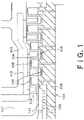
- Fig. 1 is an axial sectional view of the main components of a CO 2 turbine 101 applicable to an embodiment.
- the CO 2 turbine 101 has a casing of a dual structure having an outer casing and an inner casing 102 covered by the outer casing.
- Rotor blades 105 are annularly arranged at regular intervals in the outer radial direction of a turbine rotor 103.
- the rotor blades 105 are also arranged at predetermined intervals in the axial direction, and stationary blades 106 are arranged between the rotor blades 105 adjacent to each other in the axial direction.
- the stationary blades 106 are annularly arranged at regular intervals.
- the base of each rotor blade 105 is implanted in the outer circumferential surface of the turbine rotor 103.
- Fig. 1 shows an example of a five-stage structure alternately arranging five rotor blades 105 and five stationary blades 106 in the axial direction.
- the number of stages of the rotor blades 105 and stationary blades 106 should not be particularly restricted.
- the CO 2 turbine 101 of Fig. 1 drives the turbine rotor 103 using supercritical CO 2 as a working fluid, and cools each component by circulating CO 2 exhausted from the CO 2 turbine 101 and injecting CO 2 into the CO 2 turbine 101.
- the critical point of CO 2 is 31°C and 7.4 MPa, and the CO 2 turbine 101 of Fig. 1 is premised on using CO 2 at higher temperature and higher pressure than this critical point.
- a sleeve pipe 107 is provided upstream of the CO 2 turbine 101 of Fig. 1 , and supercritical CO 2 gas is injected from the sleeve pipe 107 into the turbine, as a working fluid.
- the injected CO 2 gas flows from upstream to downstream along the axial direction, and is exhausted from an exhaust pipe (not shown).
- the turbine rotor 103 is rotated and driven utilizing the force generated when the fluid collides with the rotor blades 105, and the fluid leaks through a gap on the outer circumferential side of the rotor blades 105 and through the gap on the inner circumferential side of the stationary blades 106.
- sealing devices 108 are arranged on the outer circumferential side of the rotor blades 105, and on the inner circumferential side of the stationary blades 106, respectively.
- the sealing device 108 has sealing fins 109 arranged at predetermined intervals at least one on the outer circumferential surface of the rotor blades 105 and the surface of the turbine rotor 103 facing the stationary blades 106, or on the outer circumferential surface of the stationary blades 106 and the surface of the stator 104 facing the rotor blades 105. By providing the sealing device 108, the gap is narrowed to prevent the leakage of the fluid.
- the sealing device 108 is provided not only on the outer circumferential surface of the rotor blades 105 or stationary blades 106 and on the surface facing the outer circumferential surface, but also on a ground packing 111 arranged on the upper side of the stationary blades 106 in the uppermost stage.
- the rotor blades 105 and the stationary blades 106 may be cooled using low-temperature CO 2 gas (hereinafter referred to as cooling CO 2 gas) supplied from the outside.
- cooling CO 2 gas low-temperature CO 2 gas
- a part of the cooling CO 2 gas passes through a fluid path 113 provided in the inner casing 102, to be utilized to cool the stationary blades 106.
- CO 2 gas used to cool the stationary blades 106 is reused to rotate and drive the turbine rotor 103, after joining the main flow passing through a fluid path 114 to drive the rotor blades 105.
- the sealing device 108 of the CO 2 turbine according to the present embodiment is characterized in its structure.
- Fig. 2 is an enlarged sectional view of the periphery of the sealing device 108.
- an arrow y1 shows a path of the cooling CO 2 gas (cooling medium) flowing from the fluid path 113 in the inner casing 102 into the stationary blade 106 through a fluid path 1 branched from the fluid path 113
- an arrow y2 shows a main flow path of high-temperature and high-pressure CO 2 gas for generating power.
- the cooling CO 2 gas flowing through the fluid path 113 provided in the inner casing 102 passes through the fluid path 1 provided on the base side of the stationary blade 106, and is introduced into the stationary blade 106 through the stator 104, to cool the stationary blade 106.
- the cooling CO 2 gas reached an inner ring 2 of the stationary blade 106 returns to an outer ring 3 of the stationary blade 106, and flows into a fluid path 4 provided in the stator 104.
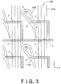
- Fig. 3 is a plane view showing an example of the fluid path 4 and a fluid path 8 connected to each other in the stator 104. Note that Fig. 3 is a plane view in the case of seeing the turbine rotor 103 from the fluid paths 4 and 8. In Fig. 3 , x-direction represents the axial direction, and y-direction represents the circumferential direction. The stationary blades 106 and the sealing fins 109 extend toward the back side of the sheet of Fig. 3 .
- the cooling CO 2 gas is introduced into the stationary blade 106 from a hole 5 formed in the stator 104 and connected to the fluid path 1 branched from the fluid path 113 in the inner casing 102.
- This cooling CO 2 gas passes through the inner ring 2 of the stationary blade 106 and flows into the fluid path 4 in the stator 104, from a hole (first hole) 6 on the outer circumferential surface of the outer ring 3.
- the fluid path 4 connected to this hole 6 extends in the axial direction, passes through a hole (second hole) 7 on the sealing device 108, and then changes the course in the circumferential direction to join the fluid path 8.
- This fluid path 8 extends in the axial direction of the stator 104, and flows the cooling CO 2 gas used to cool a plurality of stationary blades 106 arranged at the same circumferential position in the axial direction.
- the hole 7 is also provided in the fluid path 8.
- the fluid path 8 is provided corresponding to a plurality of stationary blades 106 arranged at the same circumferential position in the axial direction of the stator 104. Accordingly, if n (n is an integer of 2 or greater) stationary blades 106 are arranged in the circumferential direction, n fluid paths 8 are provided at predetermined intervals in the axial direction.
- Fig. 3 two holes 7 are provided for one stationary blade 106, and each of the holes 7 is arranged between the sealing fins 109 in the first and second stages on the upstream side.
- One hole 7 is provided on the fluid path 4, while the other hole 7 is provided on the fluid path 8.
- the cooling CO 2 gas flowing into the fluid path 4 from the hole 6 of the outer ring 3 of the stationary blade 106 partially flows into these holes 7 and cools the periphery of the sealing fins 109.
- the cooling CO 2 gas used to cool a plurality of stationary blades 106 arranged at the same circumferential position in the axial direction flows through the fluid path 8 formed in the stator 104 and extending in the axial direction.
- the hole 7 is provided on this fluid path 8 corresponding to the position of the sealing fins 109, the flow volume of cooling CO 2 gas flowing toward the sealing fins 109 from this hole 7 can be increased, which makes it possible to improve the cooling effect of the sealing fins 109.
- the sealing fins 109 can be restrained from being deformed and can be improved in durability.
- Fig. 4 is a diagram for explaining reasons why swirling flow components can be reduced.
- This is a diagram schematically showing a cross section structure of the turbine rotor 103 and stator 104 in the circumferential direction.
- the cooling CO 2 gas flowing through the hole 7 on the fluid path 4(8) is injected between the sealing fins in the first and second stages on upstream side and then flows in the radial direction.
- swirling flow components are formed in the circumferential direction of the turbine rotor 103. Since the cooling CO 2 gas obstructs the flow of swirling flow components, swirling flow components can be reduced.
- Fig. 5 is a diagram showing a modification example derived from Fig. 4.
- Fig. 5 shows an example of dividing the stator 104 into a plurality of segments (segment structures) 104a to 104d.
- the stator 104 is divided into four segments 104a to 104d, and each segment has the fluid paths 4 and 8 and the holes 7 led to the sealing fins 109.
- the fluid paths 4 and 8 and the holes 7 can be processed and formed easily, and efficiency in assembling the stator 104 can be improved.
- the number of segments is not necessarily limit to four. Considering the efficiency in manufacturing and assembling the stator 104, the number of segments should be determined depending on the number of holes 7 and fluid paths 4 and 8 to be provided in the circumferential direction. That is, by providing the holes 7 and the fluid paths 4 and 8 in each segment, the stator 104 can be manufactured relatively easily since the stator 104 can be assembled easily.
- the holes 7 are formed between the sealing fins 109 in the first and second stages on the upper side, but the holes 7 may be formed between the sealing fins 109 in the stages following the second stage.
- Fig. 6 is shows an example of forming the holes 7 between the sealing fins 109 in the first and second stages on the upper side and forming the holes 7 between the sealing fins 109 in the fourth and fifth stages.
- Figs. 1 to 5 there is no particular limitation on the shape of the holes 7 for introducing the cooling CO 2 gas from the fluid path 4(8) toward the sealing fins 109.
- the inner wall of the hole 7 is tapered.
- the hole diameter each hole 7 of Fig. 7 becomes smaller as approaching the sealing fins 109 and the rotor 103. Accordingly, the pressure of the cooling CO 2 gas passing through the holes 7 becomes higher as approaching the sealing fins 109, thereby increasing the flow velocity of the cooling CO 2 gas. Therefore, swirling flow components can be reduced more effectively while improving the cooling effect of the sealing device 108.
- a notch may be preliminarily formed on the fluid paths 4(8) at the position where the tapered hole 7 should be formed.
- Fig. 8 is shows an example of preliminarily forming a notch 9 before forming the hole 7 located between two stationary blades 106 adjacent to each other in the circumferential direction.
- the shape of the notch 9 is not limited, and it may be semicircular, for example.
- the tapered hole as shown in Fig. 7 can be formed easily by drilling the center of the notch 9.
- Fig. 7 shows a technique for increasing the flow velocity of the cooling CO 2 gas.
- Fig. 9 shows an example of deforming the sealing fin 109 near the hole 7 introducing the cooling CO 2 gas from the fluid path 4(8) to narrow the interval between the sealing fins 109 near the hole 7.
- the sealing fin 109 extending in the circumferential direction is partially deformed. More concretely, the interval between the sealing fins 109 near the hole 7 connected to the fluid path 4(8) is partially narrowed so that the flow velocity of the cooling CO 2 gas is temporarily increased in this narrowed region.
- FIG. 10 is a diagram schematically showing an example of arranging the sealing fins 109 on the turbine rotor 103. More concretely, the sealing fins 109 are arranged on the leading edge surface of the rotor blades 105 implanted in the turbine rotor 103, and on surface of the turbine rotor 103 facing the stationary blades 106 implanted in the stator 104.
- Fig. 11 shows providing a honeycomb sheet 10 on the stator 104 so that the honeycomb sheet 10 faces the sealing fins 109 provided on the turbine rotor 103.
- the honeycomb sheet 10 has a merit in that axial self-excited vibration of the shaft can be restrained, but has a demerit in its durability since the honeycomb structure is damaged by the pressure difference between the upstream side and the downstream side.
- the honeycomb sheet 10 of Fig. 11 has the hole 7 for flowing the cooling CO 2 gas from the fluid path 4(8) to the upstream side of the sealing fins 109.
- Fig. 12 is a plane view of the honeycomb sheet 10.
- the honeycomb sheet 10 has a stitch (honeycomb) structure on a basal plate 11.
- the stitch structure passes through the fluid, but the basal plate 11 blocks the passing of the fluid.
- the fluid cannot pass through the basal plate 11 if the basal plate of the honeycomb sheet is not provided with holes for passing the fluid.
- a plurality of predetermined sized holes 12 are formed in a line in the longitudinal direction of the basal plate 11 so that the cooling CO 2 gas from the fluid path can flow toward the sealing fins 109 through these holes 12. Note that where and how many holes 12 should be formed in the basal plate 11 may be arbitrarily determined, and a desired number of holes 12 should be formed corresponding to the position of the sealing fins 109.
- the fluid paths 4 and 8 are provided in the stator 104 in order to pass the cooling CO 2 gas used to cool the stationary blades 106, and the hole 7 is formed to flow the cooling CO 2 gas from the fluid path 4(8) toward the sealing fins 109 in the sealing device 108. Therefore, it is possible to reduce swirling flow components generated around the sealing fins 109 while cooling the sealing fins 109 efficiently.
- Figs. 2 to 12 shows examples for reducing swirling flow components generated around the sealing fins 109 in the CO 2 turbine shown in Fig. 1 while cooling the sealing fins 109.
- the present invention can be applied to various turbines having the sealing device 108, and should not be necessarily limited to the sealing device 108 of the CO 2 turbine. That is, the present invention can be applied to the sealing device of various types of turbines 108 involved with swirling flow components generated around the sealing fins 109.
- the CO 2 turbine 101 of Fig. 1 can be incorporated into a thermal power generating system capable of generating power while separating and recovering CO 2 .
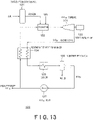
- Fig. 13 is a diagram showing a schematic structure of an example of a thermal power generating system utilizing the CO 2 turbine 101 of Fig. 1 .
- a thermal power generating system 120 of Fig. 13 has an oxygen producing device 121, a combustor 122, the CO 2 turbine 101 shown in Fig. 1 , a power generator 123, a regenerative heat exchanger 124, a cooler 125, and a moisture separator 126.
- the oxygen producing device 121 extracts only oxygen by removing nitrogen contained in air.
- the combustor 122 generates high-temperature combustion gas using the oxygen extracted by the oxygen producing device 121, fuel, and CO 2 . This combustion gas is composed of CO 2 and water.
- the fuel used by the combustor 122 is non-nitrogenous natural gas, such as methane gas.
- the high-temperature and high-pressure C0 2 gas generated by the combustor 122 is injected into the C0 2 turbine 101 shown in Fig. 1 , and used to rotate and drive the turbine rotor 103.
- the rotating shaft of the turbine rotor 103 is connected to the power generator 123, and the power generator 123 generates power utilizing the rotational driving force of the turbine rotor 103.
- C0 2 and water vapor emitted from the C0 2 turbine 101 are cooled by the regenerative heat exchanger 124, and then further cooled by the cooler 125. After that, water is removed by the moisture separator 126, and only C0 2 is extracted. This C0 2 is compressed and pressurized by a C0 2 pump. A part of the high-pressure C0 2 pressurized by the C0 2 pump is heated by the regenerative heat exchanger 124 up to about 400°C. C0 2 emitted from the regenerative heat exchanger 124 is used as cooling C0 2 for cooling the C0 2 turbine 101, and also supplied to the combustor 122.
- surplus C0 2 which is not reused to generate power through the regenerative heat exchanger 124 is recovered to be stored or utilized for another purpose (e.g., to increase the amount of oil drilling).
- the power generating system of Fig. 13 generates power using only C0 2 and water generated through combustion, and most of C0 2 is circulated and reused. Accordingly, NOx, which is a harmful gas, is not emitted, and there is no need to additionally provide a facility for separating and recovering C0 2 . Further, surplus C0 2 recovered keeping its high purity can be easily used not only for power generation but also for various other purposes.
Landscapes
- Engineering & Computer Science (AREA)
- Mechanical Engineering (AREA)
- General Engineering & Computer Science (AREA)
- Chemical & Material Sciences (AREA)
- Combustion & Propulsion (AREA)
- Physics & Mathematics (AREA)
- Fluid Mechanics (AREA)
- Turbine Rotor Nozzle Sealing (AREA)
- Engine Equipment That Uses Special Cycles (AREA)
- Sealing Using Fluids, Sealing Without Contact, And Removal Of Oil (AREA)
Claims (9)
- Dispositif d'étanchéité pour une turbine incluant :un stator (104),un rotor (103) avec une pluralité d'aubes de rotor (105), etune pluralité d'aubes fixes (106) s'étendant radialement vers l'intérieur à partir du stator (104) qui est agencé de façon à entourer les aubes de rotor (105),chacune des aubes fixes (106) étant refroidie par un fluide de refroidissement,le dispositif d'étanchéité comprenant :un élément d'étanchéité (109) ménagé dans un espace entre le rotor (103) et le stator (104),dans lequel un chemin de fluide est ménagé à l'intérieur du stator (104), pour introduire, dans le stator (104), un fluide de refroidissement utilisé pour refroidir les aubes fixes (106),caractérisé en ce que :l'élément d'étanchéité (109) est ménagé entre une extrémité de l'une des aubes de rotor (105) et le stator (104) ; etle chemin de fluide étant ménagé pour faire circuler le fluide de refroidissement vers un côté amont de l'élément d'étanchéité (109).
- Dispositif d'étanchéité selon la revendication 1,
dans lequel le chemin de fluide comprend :un premier trou (6) configuré pour recevoir le fluide de refroidissement après son utilisation pour refroidir les aubes fixes (106) ; etun second trou (7) configuré pour faire circuler le fluide de refroidissement au moins dans le côté amont de l'élément d'étanchéité (109). - Dispositif d'étanchéité selon la revendication 2,dans lequel l'élément d'étanchéité (109) présente une pluralité d'ailettes d'étanchéité agencées dans une direction axiale, etle second trou (7) est ménagé entre les ailettes d'étanchéité dans des premier et deuxième étages sur le côté amont des ailettes d'étanchéité.
- Dispositif d'étanchéité selon la revendication 3,
dans lequel une pluralité de seconds trous (7) sont ménagés, et une partie des trous (7) est ménagée entre les ailettes d'étanchéité dans des étages suivant le deuxième étage sur le côté amont des ailettes d'étanchéité. - Dispositif d'étanchéité selon la revendication 3,dans lequel le second trou (7) est ménagé entre deux ailettes d'étanchéité adjacentes l'une à l'autre, etun intervalle entre ces deux ailettes d'étanchéité est rétréci autour du second trou (7).
- Dispositif d'étanchéité selon l'une quelconque des revendications précédentes 2 à 5,
dans lequel le second trou (7) est de forme effilée de sorte qu'un diamètre du trou sur une surface plus près de l'élément d'étanchéité (109) est inférieur à un diamètre du trou sur une surface opposée. - Dispositif d'étanchéité selon l'une quelconque des revendications précédentes 2 à 6,dans lequel le stator (104) comprend une pluralité de structures de segments s'étendant dans une direction axiale, chaque structure de segment pouvant être reliée l'une à l'autre dans une direction circonférentielle, etle second trou (7) et le chemin de fluide sont ménagés dans chacune des structures de segments.
- Dispositif d'étanchéité selon l'une quelconque des revendications précédentes 2 à 7,dans lequel une feuille en nid d'abeille (10) présentant une structure de maille sur une plaque de base, la structure de maille comprenant une pluralité de trous (12) s'ouvrant vers un côté circonférentiel intérieur, la feuille en nid d'abeille (10) étant ménagée pour faire face à l'élément d'étanchéité (109) sur au moins l'une d'une surface du stator (104) faisant face aux aubes de rotor (105), et d'une surface des aubes fixes (106) faisant face à une surface circonférentielle extérieure du rotor (103), etla pluralité de trous (12) sont ménagés sur un côté amont de la plaque de base.
- Système de génération d'énergie thermique, comprenant :un dispositif de production d'oxygène (121) configuré pour extraire de l'oxygène à partir de l'air ;une chambre de combustion (122) configurée pour générer un gaz combustible composé de CO2 et d'eau, en utilisant l'oxygène extrait par le dispositif de production d'oxygène, un carburant non azoté et du CO2;une turbine à CO2 (101) configurée pour faire tourner le rotor (103) en utilisant du CO2 généré par la chambre de combustion (122) à titre de fluide de travail, tout en rejetant du CO2 et de l'eau, la turbine à CO2 (101) présentant le dispositif d'étanchéité selon l'une quelconque des revendications 1 à 8 ;un générateur d'énergie (123) configuré pour générer de l'énergie par la force d'entraînement rotative d'un arbre rotatif d'un rotor de la turbine à CO2;un échangeur de chaleur à régénération (124) configuré pour refroidir le CO2 et l'eau rejetés par la turbine à CO2;un refroidisseur (125) configuré pour refroidir davantage le CO2 et l'eau refroidis par l'échangeur de chaleur à régénération ;un séparateur d'humidité (126) configuré pour éliminer l'eau en séparant le CO2 et l'eau refroidis par le refroidisseur ; etun pressuriseur configuré pour pressuriser le CO2 séparé par le séparateur d'humidité (126),dans lequel au moins une partie du CO2 pressurisé par le pressuriseur est réchauffée par l'échangeur de chaleur à régénération (124) et ensuite injectée dans la chambre de combustion (122) et la turbine à CO2 (101).
Applications Claiming Priority (1)
| Application Number | Priority Date | Filing Date | Title |
|---|---|---|---|
| JP2012161714A JP5865798B2 (ja) | 2012-07-20 | 2012-07-20 | タービンのシール装置および火力発電システム |
Publications (3)
| Publication Number | Publication Date |
|---|---|
| EP2687681A2 EP2687681A2 (fr) | 2014-01-22 |
| EP2687681A3 EP2687681A3 (fr) | 2017-07-26 |
| EP2687681B1 true EP2687681B1 (fr) | 2022-06-15 |
Family
ID=47827026
Family Applications (1)
| Application Number | Title | Priority Date | Filing Date |
|---|---|---|---|
| EP13157966.6A Active EP2687681B1 (fr) | 2012-07-20 | 2013-03-06 | Appareil d'étanchéité de turbine et système d'énergie thermique |
Country Status (4)
| Country | Link |
|---|---|
| US (1) | US9777587B2 (fr) |
| EP (1) | EP2687681B1 (fr) |
| JP (1) | JP5865798B2 (fr) |
| CN (1) | CN103573301B (fr) |
Families Citing this family (16)
| Publication number | Priority date | Publication date | Assignee | Title |
|---|---|---|---|---|
| US9279340B2 (en) * | 2010-03-23 | 2016-03-08 | General Electric Company | System and method for cooling gas turbine components |
| JP6284447B2 (ja) * | 2014-06-27 | 2018-02-28 | 三菱日立パワーシステムズ株式会社 | 静翼ユニット及び蒸気タービン |
| JP6367064B2 (ja) * | 2014-09-19 | 2018-08-01 | 株式会社東芝 | タービン |
| US9938842B2 (en) * | 2015-01-20 | 2018-04-10 | United Technologies Corporation | Leakage air systems for turbomachines |
| US10738892B2 (en) | 2015-01-27 | 2020-08-11 | Mitsubishi Hitachi Power Systems, Ltd. | Rotary machine with seal device |
| WO2016135779A1 (fr) * | 2015-02-26 | 2016-09-01 | 株式会社 東芝 | Pale de rotor de turbine et turbine |
| JP6791777B2 (ja) | 2017-02-10 | 2020-11-25 | 三菱パワー株式会社 | 地熱タービン |
| US10781709B2 (en) * | 2018-01-09 | 2020-09-22 | General Electric Company | Turbine engine with a seal |
| JP7029317B2 (ja) * | 2018-03-09 | 2022-03-03 | 三菱重工業株式会社 | 回転機械 |
| US10941709B2 (en) * | 2018-09-28 | 2021-03-09 | Pratt & Whitney Canada Corp. | Gas turbine engine and cooling air configuration for turbine section thereof |
| FR3106609B1 (fr) * | 2020-01-27 | 2022-06-24 | Safran Aircraft Engines | Dispositif amélioré de limitation de débit de fuite pour turbines d’aéronef |
| JP7390920B2 (ja) * | 2020-02-14 | 2023-12-04 | 三菱重工業株式会社 | 昇圧装置、二酸化炭素サイクルプラント及びコンバインドサイクルプラント |
| JP7414580B2 (ja) * | 2020-02-26 | 2024-01-16 | 東芝エネルギーシステムズ株式会社 | タービン |
| CN111706405B (zh) * | 2020-05-12 | 2021-11-30 | 中国核动力研究设计院 | 一种干气密封自冷却结构及方法 |
| CN111706404B (zh) * | 2020-05-12 | 2022-08-30 | 中国核动力研究设计院 | 带螺旋冷却结构的超临界二氧化碳干气密封装置及方法 |
| CN111794807B (zh) * | 2020-06-24 | 2022-01-11 | 中船重工龙江广瀚燃气轮机有限公司 | 一种燃驱压缩机组用动力涡轮进口导向器 |
Family Cites Families (26)
| Publication number | Priority date | Publication date | Assignee | Title |
|---|---|---|---|---|
| US3291447A (en) * | 1965-02-15 | 1966-12-13 | Gen Electric | Steam turbine rotor cooling |
| IT1063035B (it) * | 1975-05-09 | 1985-02-11 | Maschf Augsburg Nuernberg Ag | Apparato per la realizzazione del procedimento per elevare il limite dinamico di potenza di turbine a vapore od a gas o di compressori |
| US4113406A (en) * | 1976-11-17 | 1978-09-12 | Westinghouse Electric Corp. | Cooling system for a gas turbine engine |
| JPS53113903A (en) * | 1977-03-16 | 1978-10-04 | Hitachi Ltd | Blade lattice device for an axial-flow fluid machine |
| JPS55123639U (fr) * | 1979-02-27 | 1980-09-02 | ||
| JPS57116103A (en) * | 1981-01-09 | 1982-07-20 | Hitachi Ltd | Preventive device for leakage of working fluid for axial-flow turbine and compressor |
| JPS6056863U (ja) * | 1983-09-27 | 1985-04-20 | 三菱重工業株式会社 | 回転機械用ラビリンスシ−ル装置 |
| JPS63205404A (ja) * | 1987-02-20 | 1988-08-24 | Toshiba Corp | 軸流タ−ビンの漏洩防止装置 |
| JP3260437B2 (ja) * | 1992-09-03 | 2002-02-25 | 株式会社日立製作所 | ガスタービン及びガスタービンの段落装置 |
| JPH0719005A (ja) * | 1993-06-30 | 1995-01-20 | Toshiba Corp | ラビリンスシール装置 |
| JP3442933B2 (ja) * | 1996-07-31 | 2003-09-02 | 三菱重工業株式会社 | 熱回収式ガスタービン |
| JPH1047083A (ja) * | 1996-07-31 | 1998-02-17 | Mitsubishi Heavy Ind Ltd | 蒸気冷却ガスタービン |
| WO1998049426A1 (fr) * | 1997-04-30 | 1998-11-05 | Mitsubishi Heavy Industries, Ltd. | Joint de rotor d'extremite a pression differentielle elevee |
| JP2003214113A (ja) * | 2002-01-28 | 2003-07-30 | Toshiba Corp | 地熱タービン |
| GB0319002D0 (en) * | 2003-05-13 | 2003-09-17 | Alstom Switzerland Ltd | Improvements in or relating to steam turbines |
| JP3977780B2 (ja) * | 2003-06-20 | 2007-09-19 | 株式会社日立製作所 | ガスタービン |
| US7654320B2 (en) * | 2006-04-07 | 2010-02-02 | Occidental Energy Ventures Corp. | System and method for processing a mixture of hydrocarbon and CO2 gas produced from a hydrocarbon reservoir |
| US8573940B2 (en) * | 2006-07-07 | 2013-11-05 | United Technologies Corporation | Interlocking knife edge seals |
| JP2008309051A (ja) * | 2007-06-14 | 2008-12-25 | Ihi Corp | タービンシュラウドの冷却構造 |
| JP2009085185A (ja) * | 2007-10-03 | 2009-04-23 | Toshiba Corp | 軸流タービンおよび軸流タービン段落構造 |
| JP2009203860A (ja) * | 2008-02-27 | 2009-09-10 | Takeo Tomota | 原動機システム |
| US8052375B2 (en) * | 2008-06-02 | 2011-11-08 | General Electric Company | Fluidic sealing for turbomachinery |
| US8079803B2 (en) * | 2008-06-30 | 2011-12-20 | Mitsubishi Heavy Industries, Ltd. | Gas turbine and cooling air supply structure thereof |
| US9074480B2 (en) * | 2009-02-25 | 2015-07-07 | Mitsubishi Hitachi Power Systems, Ltd. | Method and device for cooling steam turbine generating facility |
| JP5558120B2 (ja) * | 2010-01-12 | 2014-07-23 | 株式会社東芝 | 蒸気タービンのロータ冷却装置及びこの冷却装置を備えた蒸気タービン |
| US20120067054A1 (en) * | 2010-09-21 | 2012-03-22 | Palmer Labs, Llc | High efficiency power production methods, assemblies, and systems |
-
2012
- 2012-07-20 JP JP2012161714A patent/JP5865798B2/ja active Active
-
2013
- 2013-03-04 US US13/783,540 patent/US9777587B2/en active Active
- 2013-03-06 EP EP13157966.6A patent/EP2687681B1/fr active Active
- 2013-03-07 CN CN201310072367.XA patent/CN103573301B/zh not_active Expired - Fee Related
Also Published As
| Publication number | Publication date |
|---|---|
| EP2687681A3 (fr) | 2017-07-26 |
| CN103573301B (zh) | 2016-05-11 |
| JP5865798B2 (ja) | 2016-02-17 |
| US9777587B2 (en) | 2017-10-03 |
| JP2014020319A (ja) | 2014-02-03 |
| EP2687681A2 (fr) | 2014-01-22 |
| CN103573301A (zh) | 2014-02-12 |
| US20140020359A1 (en) | 2014-01-23 |
Similar Documents
| Publication | Publication Date | Title |
|---|---|---|
| EP2687681B1 (fr) | Appareil d'étanchéité de turbine et système d'énergie thermique | |
| US8806874B2 (en) | Axial turbine and power plant | |
| US6397604B2 (en) | Cooling supply system for stage 3 bucket of a gas turbine | |
| CN103195507B (zh) | 涡轮喷嘴区划冷却系统 | |
| JP2014020509A (ja) | シール装置、軸流タービン、および発電プラント | |
| US9382810B2 (en) | Closed loop cooling system for a gas turbine | |
| US10550698B2 (en) | Turbine | |
| US20140348642A1 (en) | Conjoined gas turbine interface seal | |
| US9228588B2 (en) | Turbomachine component temperature control | |
| EP3075986A1 (fr) | Système de gestion de température de caloduc pour roues et aubes dans une turbomachine | |
| JP2004144081A (ja) | タービン駆動装置とその冷却方法 | |
| US20130323011A1 (en) | Nozzle Diaphragm Inducer | |
| US10641174B2 (en) | Rotor shaft cooling | |
| CN103711530A (zh) | 具有冷却通道的固体密封件 | |
| JP5216802B2 (ja) | 2軸式ガスタービンの冷却空気供給構造 | |
| EP2613006A1 (fr) | Ensemble de turbine et procédé permettant de réduire l'écoulement de fluide entre des composants de turbine | |
| US9581036B2 (en) | Seal system including angular features for rotary machine components | |
| RU2664750C2 (ru) | Турбомашина с уплотнением для разделения рабочей среды и охлаждающей среды турбомашины и применение турбомашины | |
| US10605097B2 (en) | Turbine rotor blade and turbine | |
| KR101457783B1 (ko) | 컴바인드 사이클 발전 장치 |
Legal Events
| Date | Code | Title | Description |
|---|---|---|---|
| PUAI | Public reference made under article 153(3) epc to a published international application that has entered the european phase |
Free format text: ORIGINAL CODE: 0009012 |
|
| 17P | Request for examination filed |
Effective date: 20130306 |
|
| AK | Designated contracting states |
Kind code of ref document: A2 Designated state(s): AL AT BE BG CH CY CZ DE DK EE ES FI FR GB GR HR HU IE IS IT LI LT LU LV MC MK MT NL NO PL PT RO RS SE SI SK SM TR |
|
| AX | Request for extension of the european patent |
Extension state: BA ME |
|
| PUAL | Search report despatched |
Free format text: ORIGINAL CODE: 0009013 |
|
| AK | Designated contracting states |
Kind code of ref document: A3 Designated state(s): AL AT BE BG CH CY CZ DE DK EE ES FI FR GB GR HR HU IE IS IT LI LT LU LV MC MK MT NL NO PL PT RO RS SE SI SK SM TR |
|
| AX | Request for extension of the european patent |
Extension state: BA ME |
|
| RIC1 | Information provided on ipc code assigned before grant |
Ipc: F01D 25/12 20060101ALI20170621BHEP Ipc: F01D 9/06 20060101AFI20170621BHEP Ipc: F01D 11/04 20060101ALI20170621BHEP Ipc: F01D 11/00 20060101ALI20170621BHEP Ipc: F01D 11/08 20060101ALI20170621BHEP Ipc: F01D 5/18 20060101ALI20170621BHEP Ipc: F02C 7/28 20060101ALI20170621BHEP |
|
| RAP1 | Party data changed (applicant data changed or rights of an application transferred) |
Owner name: TOSHIBA ENERGY SYSTEMS & SOLUTIONS CORPORATION |
|
| STAA | Information on the status of an ep patent application or granted ep patent |
Free format text: STATUS: EXAMINATION IS IN PROGRESS |
|
| 17Q | First examination report despatched |
Effective date: 20190628 |
|
| STAA | Information on the status of an ep patent application or granted ep patent |
Free format text: STATUS: EXAMINATION IS IN PROGRESS |
|
| GRAP | Despatch of communication of intention to grant a patent |
Free format text: ORIGINAL CODE: EPIDOSNIGR1 |
|
| STAA | Information on the status of an ep patent application or granted ep patent |
Free format text: STATUS: GRANT OF PATENT IS INTENDED |
|
| INTG | Intention to grant announced |
Effective date: 20220110 |
|
| GRAS | Grant fee paid |
Free format text: ORIGINAL CODE: EPIDOSNIGR3 |
|
| GRAA | (expected) grant |
Free format text: ORIGINAL CODE: 0009210 |
|
| STAA | Information on the status of an ep patent application or granted ep patent |
Free format text: STATUS: THE PATENT HAS BEEN GRANTED |
|
| AK | Designated contracting states |
Kind code of ref document: B1 Designated state(s): AL AT BE BG CH CY CZ DE DK EE ES FI FR GB GR HR HU IE IS IT LI LT LU LV MC MK MT NL NO PL PT RO RS SE SI SK SM TR |
|
| REG | Reference to a national code |
Ref country code: CH Ref legal event code: EP Ref country code: GB Ref legal event code: FG4D |
|
| REG | Reference to a national code |
Ref country code: IE Ref legal event code: FG4D |
|
| REG | Reference to a national code |
Ref country code: DE Ref legal event code: R096 Ref document number: 602013081849 Country of ref document: DE |
|
| REG | Reference to a national code |
Ref country code: AT Ref legal event code: REF Ref document number: 1498519 Country of ref document: AT Kind code of ref document: T Effective date: 20220715 |
|
| REG | Reference to a national code |
Ref country code: LT Ref legal event code: MG9D |
|
| REG | Reference to a national code |
Ref country code: NL Ref legal event code: MP Effective date: 20220615 |
|
| PG25 | Lapsed in a contracting state [announced via postgrant information from national office to epo] |
Ref country code: SE Free format text: LAPSE BECAUSE OF FAILURE TO SUBMIT A TRANSLATION OF THE DESCRIPTION OR TO PAY THE FEE WITHIN THE PRESCRIBED TIME-LIMIT Effective date: 20220615 Ref country code: NO Free format text: LAPSE BECAUSE OF FAILURE TO SUBMIT A TRANSLATION OF THE DESCRIPTION OR TO PAY THE FEE WITHIN THE PRESCRIBED TIME-LIMIT Effective date: 20220915 Ref country code: LT Free format text: LAPSE BECAUSE OF FAILURE TO SUBMIT A TRANSLATION OF THE DESCRIPTION OR TO PAY THE FEE WITHIN THE PRESCRIBED TIME-LIMIT Effective date: 20220615 Ref country code: HR Free format text: LAPSE BECAUSE OF FAILURE TO SUBMIT A TRANSLATION OF THE DESCRIPTION OR TO PAY THE FEE WITHIN THE PRESCRIBED TIME-LIMIT Effective date: 20220615 Ref country code: GR Free format text: LAPSE BECAUSE OF FAILURE TO SUBMIT A TRANSLATION OF THE DESCRIPTION OR TO PAY THE FEE WITHIN THE PRESCRIBED TIME-LIMIT Effective date: 20220916 Ref country code: FI Free format text: LAPSE BECAUSE OF FAILURE TO SUBMIT A TRANSLATION OF THE DESCRIPTION OR TO PAY THE FEE WITHIN THE PRESCRIBED TIME-LIMIT Effective date: 20220615 Ref country code: BG Free format text: LAPSE BECAUSE OF FAILURE TO SUBMIT A TRANSLATION OF THE DESCRIPTION OR TO PAY THE FEE WITHIN THE PRESCRIBED TIME-LIMIT Effective date: 20220915 |
|
| REG | Reference to a national code |
Ref country code: AT Ref legal event code: MK05 Ref document number: 1498519 Country of ref document: AT Kind code of ref document: T Effective date: 20220615 |
|
| PG25 | Lapsed in a contracting state [announced via postgrant information from national office to epo] |
Ref country code: RS Free format text: LAPSE BECAUSE OF FAILURE TO SUBMIT A TRANSLATION OF THE DESCRIPTION OR TO PAY THE FEE WITHIN THE PRESCRIBED TIME-LIMIT Effective date: 20220615 Ref country code: LV Free format text: LAPSE BECAUSE OF FAILURE TO SUBMIT A TRANSLATION OF THE DESCRIPTION OR TO PAY THE FEE WITHIN THE PRESCRIBED TIME-LIMIT Effective date: 20220615 |
|
| PG25 | Lapsed in a contracting state [announced via postgrant information from national office to epo] |
Ref country code: NL Free format text: LAPSE BECAUSE OF FAILURE TO SUBMIT A TRANSLATION OF THE DESCRIPTION OR TO PAY THE FEE WITHIN THE PRESCRIBED TIME-LIMIT Effective date: 20220615 |
|
| PG25 | Lapsed in a contracting state [announced via postgrant information from national office to epo] |
Ref country code: SM Free format text: LAPSE BECAUSE OF FAILURE TO SUBMIT A TRANSLATION OF THE DESCRIPTION OR TO PAY THE FEE WITHIN THE PRESCRIBED TIME-LIMIT Effective date: 20220615 Ref country code: SK Free format text: LAPSE BECAUSE OF FAILURE TO SUBMIT A TRANSLATION OF THE DESCRIPTION OR TO PAY THE FEE WITHIN THE PRESCRIBED TIME-LIMIT Effective date: 20220615 Ref country code: RO Free format text: LAPSE BECAUSE OF FAILURE TO SUBMIT A TRANSLATION OF THE DESCRIPTION OR TO PAY THE FEE WITHIN THE PRESCRIBED TIME-LIMIT Effective date: 20220615 Ref country code: PT Free format text: LAPSE BECAUSE OF FAILURE TO SUBMIT A TRANSLATION OF THE DESCRIPTION OR TO PAY THE FEE WITHIN THE PRESCRIBED TIME-LIMIT Effective date: 20221017 Ref country code: ES Free format text: LAPSE BECAUSE OF FAILURE TO SUBMIT A TRANSLATION OF THE DESCRIPTION OR TO PAY THE FEE WITHIN THE PRESCRIBED TIME-LIMIT Effective date: 20220615 Ref country code: EE Free format text: LAPSE BECAUSE OF FAILURE TO SUBMIT A TRANSLATION OF THE DESCRIPTION OR TO PAY THE FEE WITHIN THE PRESCRIBED TIME-LIMIT Effective date: 20220615 Ref country code: CZ Free format text: LAPSE BECAUSE OF FAILURE TO SUBMIT A TRANSLATION OF THE DESCRIPTION OR TO PAY THE FEE WITHIN THE PRESCRIBED TIME-LIMIT Effective date: 20220615 Ref country code: AT Free format text: LAPSE BECAUSE OF FAILURE TO SUBMIT A TRANSLATION OF THE DESCRIPTION OR TO PAY THE FEE WITHIN THE PRESCRIBED TIME-LIMIT Effective date: 20220615 |
|
| PG25 | Lapsed in a contracting state [announced via postgrant information from national office to epo] |
Ref country code: PL Free format text: LAPSE BECAUSE OF FAILURE TO SUBMIT A TRANSLATION OF THE DESCRIPTION OR TO PAY THE FEE WITHIN THE PRESCRIBED TIME-LIMIT Effective date: 20220615 Ref country code: IS Free format text: LAPSE BECAUSE OF FAILURE TO SUBMIT A TRANSLATION OF THE DESCRIPTION OR TO PAY THE FEE WITHIN THE PRESCRIBED TIME-LIMIT Effective date: 20221015 |
|
| REG | Reference to a national code |
Ref country code: DE Ref legal event code: R097 Ref document number: 602013081849 Country of ref document: DE |
|
| PG25 | Lapsed in a contracting state [announced via postgrant information from national office to epo] |
Ref country code: AL Free format text: LAPSE BECAUSE OF FAILURE TO SUBMIT A TRANSLATION OF THE DESCRIPTION OR TO PAY THE FEE WITHIN THE PRESCRIBED TIME-LIMIT Effective date: 20220615 |
|
| PLBE | No opposition filed within time limit |
Free format text: ORIGINAL CODE: 0009261 |
|
| STAA | Information on the status of an ep patent application or granted ep patent |
Free format text: STATUS: NO OPPOSITION FILED WITHIN TIME LIMIT |
|
| PG25 | Lapsed in a contracting state [announced via postgrant information from national office to epo] |
Ref country code: DK Free format text: LAPSE BECAUSE OF FAILURE TO SUBMIT A TRANSLATION OF THE DESCRIPTION OR TO PAY THE FEE WITHIN THE PRESCRIBED TIME-LIMIT Effective date: 20220615 |
|
| 26N | No opposition filed |
Effective date: 20230316 |
|
| PG25 | Lapsed in a contracting state [announced via postgrant information from national office to epo] |
Ref country code: SI Free format text: LAPSE BECAUSE OF FAILURE TO SUBMIT A TRANSLATION OF THE DESCRIPTION OR TO PAY THE FEE WITHIN THE PRESCRIBED TIME-LIMIT Effective date: 20220615 |
|
| PG25 | Lapsed in a contracting state [announced via postgrant information from national office to epo] |
Ref country code: MC Free format text: LAPSE BECAUSE OF FAILURE TO SUBMIT A TRANSLATION OF THE DESCRIPTION OR TO PAY THE FEE WITHIN THE PRESCRIBED TIME-LIMIT Effective date: 20220615 |
|
| REG | Reference to a national code |
Ref country code: CH Ref legal event code: PL |
|
| GBPC | Gb: european patent ceased through non-payment of renewal fee |
Effective date: 20230306 |
|
| REG | Reference to a national code |
Ref country code: BE Ref legal event code: MM Effective date: 20230331 |
|
| PG25 | Lapsed in a contracting state [announced via postgrant information from national office to epo] |
Ref country code: LU Free format text: LAPSE BECAUSE OF NON-PAYMENT OF DUE FEES Effective date: 20230306 |
|
| REG | Reference to a national code |
Ref country code: IE Ref legal event code: MM4A |
|
| PG25 | Lapsed in a contracting state [announced via postgrant information from national office to epo] |
Ref country code: GB Free format text: LAPSE BECAUSE OF NON-PAYMENT OF DUE FEES Effective date: 20230306 |
|
| PG25 | Lapsed in a contracting state [announced via postgrant information from national office to epo] |
Ref country code: LI Free format text: LAPSE BECAUSE OF NON-PAYMENT OF DUE FEES Effective date: 20230331 Ref country code: IT Free format text: LAPSE BECAUSE OF FAILURE TO SUBMIT A TRANSLATION OF THE DESCRIPTION OR TO PAY THE FEE WITHIN THE PRESCRIBED TIME-LIMIT Effective date: 20220615 Ref country code: IE Free format text: LAPSE BECAUSE OF NON-PAYMENT OF DUE FEES Effective date: 20230306 Ref country code: GB Free format text: LAPSE BECAUSE OF NON-PAYMENT OF DUE FEES Effective date: 20230306 Ref country code: FR Free format text: LAPSE BECAUSE OF NON-PAYMENT OF DUE FEES Effective date: 20230331 Ref country code: CH Free format text: LAPSE BECAUSE OF NON-PAYMENT OF DUE FEES Effective date: 20230331 |
|
| PG25 | Lapsed in a contracting state [announced via postgrant information from national office to epo] |
Ref country code: BE Free format text: LAPSE BECAUSE OF NON-PAYMENT OF DUE FEES Effective date: 20230331 |
|
| PGFP | Annual fee paid to national office [announced via postgrant information from national office to epo] |
Ref country code: DE Payment date: 20231229 Year of fee payment: 12 |