EP2685899B1 - Multiple modality cardiac imaging - Google Patents
Multiple modality cardiac imaging Download PDFInfo
- Publication number
- EP2685899B1 EP2685899B1 EP20120713340 EP12713340A EP2685899B1 EP 2685899 B1 EP2685899 B1 EP 2685899B1 EP 20120713340 EP20120713340 EP 20120713340 EP 12713340 A EP12713340 A EP 12713340A EP 2685899 B1 EP2685899 B1 EP 2685899B1
- Authority
- EP
- European Patent Office
- Prior art keywords
- projection data
- nuclear
- angiogram
- image representation
- projection
- Prior art date
- Legal status (The legal status is an assumption and is not a legal conclusion. Google has not performed a legal analysis and makes no representation as to the accuracy of the status listed.)
- Not-in-force
Links
Images

Classifications
-
- A—HUMAN NECESSITIES
- A61—MEDICAL OR VETERINARY SCIENCE; HYGIENE
- A61B—DIAGNOSIS; SURGERY; IDENTIFICATION
- A61B6/00—Apparatus or devices for radiation diagnosis; Apparatus or devices for radiation diagnosis combined with radiation therapy equipment
- A61B6/50—Apparatus or devices for radiation diagnosis; Apparatus or devices for radiation diagnosis combined with radiation therapy equipment specially adapted for specific body parts; specially adapted for specific clinical applications
- A61B6/504—Apparatus or devices for radiation diagnosis; Apparatus or devices for radiation diagnosis combined with radiation therapy equipment specially adapted for specific body parts; specially adapted for specific clinical applications for diagnosis of blood vessels, e.g. by angiography
-
- A—HUMAN NECESSITIES
- A61—MEDICAL OR VETERINARY SCIENCE; HYGIENE
- A61B—DIAGNOSIS; SURGERY; IDENTIFICATION
- A61B6/00—Apparatus or devices for radiation diagnosis; Apparatus or devices for radiation diagnosis combined with radiation therapy equipment
- A61B6/02—Arrangements for diagnosis sequentially in different planes; Stereoscopic radiation diagnosis
- A61B6/03—Computed tomography [CT]
- A61B6/032—Transmission computed tomography [CT]
- A61B6/035—Mechanical aspects of CT
-
- A—HUMAN NECESSITIES
- A61—MEDICAL OR VETERINARY SCIENCE; HYGIENE
- A61B—DIAGNOSIS; SURGERY; IDENTIFICATION
- A61B6/00—Apparatus or devices for radiation diagnosis; Apparatus or devices for radiation diagnosis combined with radiation therapy equipment
- A61B6/02—Arrangements for diagnosis sequentially in different planes; Stereoscopic radiation diagnosis
- A61B6/03—Computed tomography [CT]
- A61B6/037—Emission tomography
-
- A—HUMAN NECESSITIES
- A61—MEDICAL OR VETERINARY SCIENCE; HYGIENE
- A61B—DIAGNOSIS; SURGERY; IDENTIFICATION
- A61B6/00—Apparatus or devices for radiation diagnosis; Apparatus or devices for radiation diagnosis combined with radiation therapy equipment
- A61B6/42—Arrangements for detecting radiation specially adapted for radiation diagnosis
- A61B6/4208—Arrangements for detecting radiation specially adapted for radiation diagnosis characterised by using a particular type of detector
- A61B6/4258—Arrangements for detecting radiation specially adapted for radiation diagnosis characterised by using a particular type of detector for detecting non x-ray radiation, e.g. gamma radiation
-
- A—HUMAN NECESSITIES
- A61—MEDICAL OR VETERINARY SCIENCE; HYGIENE
- A61B—DIAGNOSIS; SURGERY; IDENTIFICATION
- A61B6/00—Apparatus or devices for radiation diagnosis; Apparatus or devices for radiation diagnosis combined with radiation therapy equipment
- A61B6/44—Constructional features of apparatus for radiation diagnosis
- A61B6/4417—Constructional features of apparatus for radiation diagnosis related to combined acquisition of different diagnostic modalities
-
- A—HUMAN NECESSITIES
- A61—MEDICAL OR VETERINARY SCIENCE; HYGIENE
- A61B—DIAGNOSIS; SURGERY; IDENTIFICATION
- A61B6/00—Apparatus or devices for radiation diagnosis; Apparatus or devices for radiation diagnosis combined with radiation therapy equipment
- A61B6/48—Diagnostic techniques
- A61B6/481—Diagnostic techniques involving the use of contrast agents
-
- A—HUMAN NECESSITIES
- A61—MEDICAL OR VETERINARY SCIENCE; HYGIENE
- A61B—DIAGNOSIS; SURGERY; IDENTIFICATION
- A61B6/00—Apparatus or devices for radiation diagnosis; Apparatus or devices for radiation diagnosis combined with radiation therapy equipment
- A61B6/50—Apparatus or devices for radiation diagnosis; Apparatus or devices for radiation diagnosis combined with radiation therapy equipment specially adapted for specific body parts; specially adapted for specific clinical applications
- A61B6/503—Apparatus or devices for radiation diagnosis; Apparatus or devices for radiation diagnosis combined with radiation therapy equipment specially adapted for specific body parts; specially adapted for specific clinical applications for diagnosis of the heart
-
- A—HUMAN NECESSITIES
- A61—MEDICAL OR VETERINARY SCIENCE; HYGIENE
- A61B—DIAGNOSIS; SURGERY; IDENTIFICATION
- A61B6/00—Apparatus or devices for radiation diagnosis; Apparatus or devices for radiation diagnosis combined with radiation therapy equipment
- A61B6/52—Devices using data or image processing specially adapted for radiation diagnosis
- A61B6/5205—Devices using data or image processing specially adapted for radiation diagnosis involving processing of raw data to produce diagnostic data
-
- A—HUMAN NECESSITIES
- A61—MEDICAL OR VETERINARY SCIENCE; HYGIENE
- A61B—DIAGNOSIS; SURGERY; IDENTIFICATION
- A61B6/00—Apparatus or devices for radiation diagnosis; Apparatus or devices for radiation diagnosis combined with radiation therapy equipment
- A61B6/52—Devices using data or image processing specially adapted for radiation diagnosis
- A61B6/5211—Devices using data or image processing specially adapted for radiation diagnosis involving processing of medical diagnostic data
- A61B6/5229—Devices using data or image processing specially adapted for radiation diagnosis involving processing of medical diagnostic data combining image data of a patient, e.g. combining a functional image with an anatomical image
- A61B6/5235—Devices using data or image processing specially adapted for radiation diagnosis involving processing of medical diagnostic data combining image data of a patient, e.g. combining a functional image with an anatomical image combining images from the same or different ionising radiation imaging techniques, e.g. PET and CT
-
- A—HUMAN NECESSITIES
- A61—MEDICAL OR VETERINARY SCIENCE; HYGIENE
- A61B—DIAGNOSIS; SURGERY; IDENTIFICATION
- A61B6/00—Apparatus or devices for radiation diagnosis; Apparatus or devices for radiation diagnosis combined with radiation therapy equipment
- A61B6/52—Devices using data or image processing specially adapted for radiation diagnosis
- A61B6/5258—Devices using data or image processing specially adapted for radiation diagnosis involving detection or reduction of artifacts or noise
-
- A—HUMAN NECESSITIES
- A61—MEDICAL OR VETERINARY SCIENCE; HYGIENE
- A61B—DIAGNOSIS; SURGERY; IDENTIFICATION
- A61B6/00—Apparatus or devices for radiation diagnosis; Apparatus or devices for radiation diagnosis combined with radiation therapy equipment
- A61B6/52—Devices using data or image processing specially adapted for radiation diagnosis
- A61B6/5288—Devices using data or image processing specially adapted for radiation diagnosis involving retrospective matching to a physiological signal
-
- G—PHYSICS
- G06—COMPUTING OR CALCULATING; COUNTING
- G06T—IMAGE DATA PROCESSING OR GENERATION, IN GENERAL
- G06T11/00—2D [Two Dimensional] image generation
- G06T11/003—Reconstruction from projections, e.g. tomography
- G06T11/006—Inverse problem, transformation from projection-space into object-space, e.g. transform methods, back-projection, algebraic methods
-
- A—HUMAN NECESSITIES
- A61—MEDICAL OR VETERINARY SCIENCE; HYGIENE
- A61B—DIAGNOSIS; SURGERY; IDENTIFICATION
- A61B6/00—Apparatus or devices for radiation diagnosis; Apparatus or devices for radiation diagnosis combined with radiation therapy equipment
- A61B6/44—Constructional features of apparatus for radiation diagnosis
- A61B6/4429—Constructional features of apparatus for radiation diagnosis related to the mounting of source units and detector units
-
- A—HUMAN NECESSITIES
- A61—MEDICAL OR VETERINARY SCIENCE; HYGIENE
- A61B—DIAGNOSIS; SURGERY; IDENTIFICATION
- A61B6/00—Apparatus or devices for radiation diagnosis; Apparatus or devices for radiation diagnosis combined with radiation therapy equipment
- A61B6/46—Arrangements for interfacing with the operator or the patient
- A61B6/461—Displaying means of special interest
- A61B6/463—Displaying means of special interest characterised by displaying multiple images or images and diagnostic data on one display
-
- A—HUMAN NECESSITIES
- A61—MEDICAL OR VETERINARY SCIENCE; HYGIENE
- A61B—DIAGNOSIS; SURGERY; IDENTIFICATION
- A61B6/00—Apparatus or devices for radiation diagnosis; Apparatus or devices for radiation diagnosis combined with radiation therapy equipment
- A61B6/46—Arrangements for interfacing with the operator or the patient
- A61B6/461—Displaying means of special interest
- A61B6/466—Displaying means of special interest adapted to display 3D data
-
- A—HUMAN NECESSITIES
- A61—MEDICAL OR VETERINARY SCIENCE; HYGIENE
- A61B—DIAGNOSIS; SURGERY; IDENTIFICATION
- A61B6/00—Apparatus or devices for radiation diagnosis; Apparatus or devices for radiation diagnosis combined with radiation therapy equipment
- A61B6/50—Apparatus or devices for radiation diagnosis; Apparatus or devices for radiation diagnosis combined with radiation therapy equipment specially adapted for specific body parts; specially adapted for specific clinical applications
- A61B6/506—Apparatus or devices for radiation diagnosis; Apparatus or devices for radiation diagnosis combined with radiation therapy equipment specially adapted for specific body parts; specially adapted for specific clinical applications for diagnosis of nerves
-
- G—PHYSICS
- G06—COMPUTING OR CALCULATING; COUNTING
- G06T—IMAGE DATA PROCESSING OR GENERATION, IN GENERAL
- G06T2211/00—Image generation
- G06T2211/40—Computed tomography
- G06T2211/404—Angiography
-
- G—PHYSICS
- G06—COMPUTING OR CALCULATING; COUNTING
- G06T—IMAGE DATA PROCESSING OR GENERATION, IN GENERAL
- G06T2211/00—Image generation
- G06T2211/40—Computed tomography
- G06T2211/412—Dynamic
-
- G—PHYSICS
- G06—COMPUTING OR CALCULATING; COUNTING
- G06T—IMAGE DATA PROCESSING OR GENERATION, IN GENERAL
- G06T2211/00—Image generation
- G06T2211/40—Computed tomography
- G06T2211/432—Truncation
Definitions
- the present application relates to medical imaging arts. It finds particular application in coronary artery imaging and perfusion studies using multiple modality imaging systems which perform both nuclear imaging and x-ray/CT imaging.
- radiopharmaceutical In diagnostic nuclear imaging, a radionuclide distribution is studied as it passes through a patient's bloodstream for imaging the circulatory system or for imaging specific organs that accumulate the injected radiopharmaceutical.
- the radiopharmaceutical can be designed to concentrate in selected tissues to provide preferential imaging of those selected tissues.
- each gamma camera includes a radiation detector array and a collimator disposed in front of the radiation detector array.
- the collimator defines a linear or small-angle conical line of sight so that the detected radiation represents projection data. If the gamma cameras are moved over a range of angular views, for example over a 180° or 360° angular range, then the resulting projection data can be readily reconstructed into an image of the radiopharmaceutical distribution in the patient.
- positron emission tomography PET
- the radioactive decay events of the radiopharmaceutical produce positrons.
- Each positron interacts with an electron to produce a positron-electron annihilation event that emits two 180° oppositely directed gamma rays.
- coincidence detection circuitry Using coincidence detection circuitry, a ring array of radiation detectors surrounding the imaging patient detect the coincident oppositely directed gamma ray events corresponding to the positron-electron annihilation.
- a line of response (LOR) connecting the two coincident detections contains the position of the positron-electron annihilation event. Such lines of response can be reconstructed to produce an image of the radiopharmaceutical distribution.
- time-of-flight PET In time-of-flight PET (TOF-PET), the small time difference between the detection times of the two coincident y ray events is used to localize the annihilation event along the LOR (line of response).
- a radiation source irradiates an imaging subject; and a radiation detector array disposed on the opposite side of the imaging subject detects the transmitted radiation. Due to varying attenuations of radiation by tissues in the imaging subject, the detected radiation can be reconstructed into an image depicting radiation-absorbing structures in the imaging subject.
- CT computed tomography
- Diagnosis and treatment planning for coronary artery disease can be performed using different imaging modalities.
- the most common imaging procedures include myocardial perfusion with nuclear imaging systems, namely SPECT though PET can also be used, and planar x-ray coronary angiography are used to detect coronary artery stenosis and corresponding perfusion defects. While planar 2D angiography is currently preferred in clinical settings due to cost and availability, 3D CT coronary artery imaging is gaining popularity because it offers more information, is potentially easier to interpret than a series of 2D projection images from different angles, and provides quantitative analysis of vessel properties useful in intervention and planning.
- the more common catheter-based x-ray coronary angiography is generally performed on a C-arm x-ray system.
- the C-arm system's flat-panel x-ray detector delivers high-resolution planar 2D angiograms.
- 3D coronary artery imaging is also possible on the C-arm x-ray system by using a rotational angiography (3DRA) acquisition in conjunction with specially adapted reconstruction algorithms.
- 3D coronary artery imaging can be performed with a standard x-ray CT system.
- these examinations cannot provide the same functional information as a SPECT scan.
- Combining cardiac SPECT and x-ray/CT angiography imaging can improve the diagnosis of cardiac disease by combining functional and anatomic information about the health of the heart and, in particular, of the coronary arteries.
- SPECT and x-ray imaging procedures are carried out on separate imaging systems and therefore at different times and locations. It is advantageous to perform both procedures on the same imaging device, to increase patient throughput, reduce risk of mis-registrations or anatomical changes between exams, and increase patient comfort by shortening the total examination time.
- a standard CT delivers inherently lower imaging resolution than a flat-panel based system and does not provide planar angiograms.
- co-planar SPECT and CT imaging is not possible when using a standard SPECT/CT system, because the two imaging systems are mounted on two separate rotation gantries.
- WO2009/060344 A2 discloses a method according to the preamble of claim 1.
- the present application provides a new and improved multiple modality imaging system and method which overcomes the above-referenced problems and others.
- a method for diagnostic imaging includes receiving contrast enhanced CT projection data acquired from an examination region with a laterally offset flat panel detector.
- a field-of-view (FOV) which includes one or more contrast enhanced vessels is selected.
- FOV field-of-view
- a three-dimensional (3D) vessel image representation, at least one planar vessel angiogram, and a 3D attenuation correction (AC) map of the selected FOV are generated.
- the step of generating the 3D attenuation correction map includes: segmenting the contrast enhanced vessels in the 3D volume representation, replacing the segmented contrast enhanced vessels with background intensity data, and generating the 3D attenuation correction map based on the CT projection data in which the contrast enhanced vessels are subtracted and replaced with background intensity data.
- nuclear projection data acquired from the examination region are received.
- the acquired nuclear projection data are then corrected based on the generated 3D attenuation correction map, and finally a nuclear image representation of the selected FOV is generated from the acquired nuclear projection data based on the corrected nuclear projection data.
- a diagnostic imaging system comprises an x-ray scanner which acquires contrast enhanced CT projection data from an examination region with a laterally offset flat panel detector.
- the system includes a graphical user interface for selecting a field-of-view (FOV) which includes one or more contrast enhanced vessels.
- FOV field-of-view
- a CT reconstruction processor generates a three-dimensional (3D) vessel image representation, at least one planar vessel angiogram, and a 3D attenuation correction (AC) map of the selected FOV from the acquired CT projection data, wherein the CT reconstruction processor is further configured to segment the contrast enhanced vessels in the 3D volume representation, to replace the segmented contrast enhanced vessels with background intensity data, and to generate the 3D attenuation correction map based on the CT projection data in which the contrast enhanced vessels were subtracted and replaced with background intensity data.
- the system further includes a nuclear imaging scanner which acquires nuclear projection data from the examination region.
- a nuclear reconstruction processor is programmed to correct the acquired nuclear projection data based on the generated attenuation correction map, and to generate a nuclear image representation of the selected FOV from the acquired nuclear projection data based on the corrected nuclear projection data.
- Another advantage is that diagnosis of coronary artery disease is improved. Another advantage resides in reduced examination costs and total examination times.
- Another advantage is that the risk of mis-registration is reduced.
- Another advantage is that the risk of reduced data quality caused by patient motion and/or anatomical changes between examinations is reduced.
- the invention may take form in various components and arrangements of components, and in various steps and arrangements of steps.
- the drawings are only for purposes of illustrating the preferred embodiments and are not to be construed as limiting the invention.
- a multiple modality diagnostic imaging system capable of x-ray CT and nuclear imaging acquisitions, enables comprehensive assessment of coronary artery disease with a single x-ray CT acquisition.
- a cardiac perfusion SPECT reconstruction, 2D x-ray angiograms, and a 3D x-ray coronary artery reconstruction are generated.
- the system improves diagnosis of coronary artery disease by generating more comprehensive examinations which are accessible to more patients, reducing examination costs and total examination times, and by reducing risk of mis-registration and mis-diagnosis caused by patient motion and anatomical changes between imaging exams.
- the system is not limited to cardiac imaging studies and can be applied to study various vasculature studies through a patient's body, such as neural.
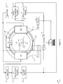
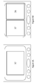
- a diagnostic imaging system 10 performs concurrently and/or independently x-ray computed tomography (CT) and nuclear imaging, such as PET or SPECT.
- CT computed tomography
- the imaging system 10 includes a stationary housing 12 which defines a patient receiving bore 14.
- a rotatable gantry 16, supported by the housing 12, is arranged for rotation around the bore to define a common examination region 18.
- a patient support 20, which supports a patient or subject 22 to be imaged and/or examined, is longitudinally and/or vertically adjusted to achieve the desired positioning of the patient in the examination region.
- an x-ray assembly 24 which is mounted on the rotatable gantry 16 includes an x-ray source 26, such as an x-ray tube, and a collimator or shutter assembly 28 which, in addition to the collimator, may include various filters to modify the spectral characteristics of the emitted x-ray radiation.
- the collimator collimates the radiation from the x-ray source 26 into a cone or wedge beam, one or more substantially parallel fan beams, or the like.
- the shutter gates the beam on and off.
- An x-ray detector 30, such as a solid state, flat panel detector, is mounted on the rotatable gantry 16 opposite the x-ray assembly 24.
- the detector panel is laterally offset relative to the projected center of radiation or transversely displaced from the center of rotation in the trans-axial plane. More specifically, the cone beam and the CT detector 30 are offset such that slightly more than half of the field-of-view (FoV) is examined in each single x-ray projection. The whole FoV can be examined when the x-ray source and the detector rotate approximately 360°. Offset detector geometries are desirable because they allow for an increased FoV given a fixed detector size or allow for smaller detectors sizes. Larger detectors tend to be more complex, expensive to manufacture, can limit the overall system design, and can limit detector positioning or patient access or the like.
- FoV field-of-view
- the x-ray assembly 24 and the x-ray detector 30 revolve in concert around the examination region 18 to acquire CT projection data spanning a full 360° revolution, multiple revolutions, or a smaller arc.
- Each CT projection indicates x-ray attenuation along a linear path between the x-ray assembly 24 and a detecting element of the x-ray detector 30.
- the acquired CT projection data is stored in a CT data buffer 32 and processed by a CT reconstruction processor 34 into a CT image representation and then stored in a CT image memory unit 36.
- the x-ray source, the collimator/shutter assembly, the detector, and the reconstruction processor define a system or means for generating an anatomical, CT, x-ray, or first image.
- At least two nuclear detector heads 40a, 40b are moveably mounted to the rotating gantry 16.
- Mounting the x-ray assembly 24 and the nuclear detector heads 40a, 40b on the same rotatable gantry permits the examination region 18 to be imaged by both modalities without moving the patient 22 ,i.e. co-planar imaging.
- the detector heads are moveably supported by a robotic assembly (not shown) which is mounted to the rotating gantry 16.
- the robotic assembly enables the detector heads to be positioned at a selectable offset about the patient 22, e.g. 90° offset, 180° opposite each other, etc.
- Each SPECT detector head includes a collimator such that each detected radiation event is known to have originated along an identifiable linear or small-angle conical line of sight so that the acquired radiation comprises projection data.
- the acquired SPECT projection data is stored in a data buffer 42 and processed by a SPECT reconstruction processor 44 into a SPECT image representation and stored in a SPECT image memory unit 46.
- the SPECT detector heads and the SPECT reconstruction processor define a system or means for generating a nuclear, functional, or second image.
- the nuclear imaging system or means includes positron emission tomography (PET) detectors, not illustrated, rather than the SPECT detectors 40a, 40b.
- PET positron emission tomography
- One or more rings of PET detectors are arranged about the patient receiving bore 14 to receive gamma radiation therefrom. Detected pairs of coincident radiation events define LORs which are stored in list mode in a data buffer and processed by a PET reconstruction processor into a PET image representation and stored in a PET image memory unit. Taken together, the PET detector ring(s) and the PET reconstruction processor define the system or means for generating the functional image. It should be appreciated that the combination of a flat panel x-ray assembly 24 and a PET system in a single gantry is not illustrated but is also contemplated.
- Combining cardiac SPECT and CT angiography imaging can improve diagnosis of cardiac disease by combining functional and anatomical information about the health of the heart and the coronary arteries.
- the imagining system 10 can acquire co-planar SPECT and CT images along with non-truncated attenuation correction (AC) maps which are then reconstructed and presented to a clinician as fused and non-fused views on a display.
- AC non-truncated attenuation correction
- a patient 22 is positioned on the support 20.
- An electrocardiogram (ECG) recording device 50 is positioned on or near the patient to record the patients ECG signal during CT and SPECT data acquisition to gate the acquired projection data.
- ECG signal can be replaced by suitable methods that derive the subject's heart phase based on the acquired image data, e.g. CT or nuclear image data, without using the additional EGC recording device 50.
- An x-ray contrast enhancing agent is administered to the patient to enhance the contrast of the coronary arteries during acquisition.
- the contrast agent is injected intravenously or via a catheter directly into the coronary arteries such that a constant concentration of the contrast agent is present in the coronary arteries throughout the CT acquisition.
- a 360-degree x-ray acquisition is performed using the CT component of the system 10 which consists of the x-ray source 26 and the laterally offset flat-panel x-ray detector 30, mounted on the same gantry as the SPECT detector heads 40a, 40b.
- the detector offset enables imaging over the entire patient axial cross-section.
- Each X-ray projection covers slightly more than half of the patient.
- the ECG recording device 50 the patient's ECG signal is recorded during the CT acquisition and is temporally registered to the x-ray acquisition.
- the acquired CT projection data and corresponding ECG data are stored in the CT data buffer 32.
- a 3D reconstruction of the coronary arteries is generated from the stored CT projection data that represent a selected cardiac motion state.
- a clinician selects a cardiac motion state for reconstruction, e.g. in the late diastole where heart motion is relatively small.
- the CT reconstruction processor 34 automatically selects the optimum cardiac motion state. The corresponding projections for reconstruction are determined according to the ECG gating signal and the selected optimum cardiac motion state.
- the CT reconstruction processor 34 is programmed to pre-filter the gated CT projection data to enhance the coronary arteries and reduce the anatomic background.
- Filtering methods include morphological filtering such as a 'top-hat' filter, multi-scale vesselness filtering with vessel segmentation, a combination of these two methods, or other known filtering methods.
- the background removal is beneficial in order to achieve high-quality coronary artery iterative reconstruction from few projections, which will be later described, to enable reconstruction of high-resolution sub-volume image representation containing only the coronary arteries.
- the reconstruction processor 34 performs a Few-Projections reconstruction algorithm.
- the reconstruction algorithm is an iterative reconstruction method which uses at least one of the spatial sparseness of the coronary arteries as a regularization factor, a redundancy weighting factor to account for the central overlap region, and a small update step to achieve uniform convergence with the truncated projection data and non-uniform volume coverage.
- the reconstruction can be performed in a small, high-resolution sub-volume containing the coronary arteries only. Also, several motion states can be reconstructed to generate an image in each motion state.
- the reconstruction can incorporate motion estimation and motion correction steps, e.g., projection-based motion correction or volume-based motion estimation and correction, to correct for cardiac motion or other residual motion.
- a motion model can be derived which models the motion between motion states.
- the motion model can be used to map or transform images or the underlying projection data from other motion states into the selected motion state.
- the reconstructed 3D coronary image representation is stored to the CT image memory 36.
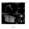
- FIGURE 2 displays an example of an ECG-gated coronary artery reconstruction 37 in a software phantom study for a simulated offset-detector flat-panel X-ray acquisition.
- the 3D high-resolution reconstruction of the coronary arteries was generated from 18 projections that were equi-angularly spaced over 360°.
- the projection selection corresponds to a nearest-neighbor ECG gating on a 12 second scan time at a heart rate of 90 bpm.
- the reconstruction was generated from top-hat filtered projections using the iterative reconstruction method which uses the sparseness regularization, redundancy weighting factor, and a small update step.
- At least one 2D angiogram is generated from the acquired CT projection data of the selected cardiac motion state.
- the selected projection data can be filtered to enhance the visibility of the coronary arteries using known filter methods, such as contrast enhancement, histogram optimization, vesselness filtering and vessel segmentation, or morphological filters.
- the CT reconstruction processor 34 selects the corresponding x-ray projection stored in the buffer 32.
- the selected projection shows the coronary artery tree truncated because the offset-detector geometry captures a little over half of the FOV.
- a second projection acquired in the same cardiac motion state as the first is selected from the buffer 32 such that the difference between the projection angles of the first and second projection is as close to 180° degrees as possible.
- the CT reconstruction processor 34 fuses the two projections resulting in one 2-D angiogram for the two given projection angles and stores the composite 2D angiograms to the CT image memory 36.
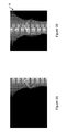
- Figures 3A and 3B display an example of a first 2D truncated angiogram and the fused 2-D angiogram 38, respectively.
- an attenuation correction (AC) map is generated from the acquired CT projection data.
- the presence of the contrast enhancing agent in the CT projections scan can interfere in the generation of an accurate AC map because the contrast agent is not present during the SPECT acquisition.
- the AC map with the contrast enhancing agent present in the coronary arteries can produce inconsistent attenuation information for SPECT reconstruction correction.
- the CT reconstruction processor 34 segments the contrast enhanced vessels in the projection data using known methods and replaces the segmented regions with a background intensity. According to the present invention, the CT reconstruction processor 34 segments and replaces the contrast enhanced vessels in the reconstructed 3D image data rather than the projection data, i.e. after the projection data is reconstructed into a 3D volume representation.
- the CT reconstruction processor 34 can segment the contrast enhanced vessels in the 3D volume representation; a forward projection of the segmented vessels can then be subtracted from the projection data.
- a 3D reconstruction is performed using known methods for cone-beam CT reconstruction with a laterally offset-detector flat-panel system, such as a filtered backprojection or an iterative reconstruction method.
- the generated 3D volume can be post-processed for noise removal, truncation correction, contrast medium reduction, or resolution adaptation like down-sampling.
- the AC map is generated from this 3D reconstruction volume.
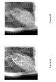
- FIGURE 4A is an example of a 2D angiogram from a C-arm rotational angiography acquisition and FIGURE 4B is the angiogram after removal of contrast-enhanced vessels.
- the contrast enhanced vessels were detected and segmented using a multi-scale vesselness filter, subtracted, and replaced with interpolated projection background.
- the acquired CT projection data yields a 3D coronary artery reconstruction, a series of 2D angiograms, and an attenuation correction map that can be used to correct analogous SPECT projection data.
- the SPECT projection data can be acquired before, after, or interleaved with the CT data acquisition.
- the patient which remains stationary in the examination region 18, is administered a radiopharmaceutical tracer.
- the SPECT projection data and an ECG gating signal are acquired concurrently and stored on the SPECT image memory 46.
- the SPECT reconstruction processor corrects the SPECT projection data based on the AC map and generates a 3D image reconstruction from the corrected SPECT data according to the selected cardiac phase.
- the image representations e.g. the reconstructed 3D vessel representation, 2D angiograms, and corrected SPECT reconstructions, are visualized by a clinician on a graphical user interface (GUI) 52.
- GUI graphical user interface
- the GUI includes also includes a user input device by which the clinician or user interacts with the system 10 .
- the clinician can instruct the GUI 52 to display one of the image representation at a higher resolution to encompass the entire display of the GUI 52.
- the clinician instructs the GUI to display the reconstructed 3D coronary artery tree.
- the clinician can use the user input device to rotate the 3D coronary artery tree to visualize the arteries at various arteries.
- the clinician can instruct the GUI 52 to display the 2D angiogram which corresponds to the rotation angle of the current view.
- more than one image representation can be visualized concurrently.
- the clinician can instruct the GUI 52 to display the corresponding 2D angiogram beside the 3D coronary artery reconstruction.
- the clinician can display the corrected 3D SPECT reconstruction concurrently with the 3D coronary artery reconstruction at the corresponding rotation angle and/or with a corresponding 2D angiogram.
- the image representations are displayed in various superimpositions.
- the imaging system 10 includes a fusion processor 54 which is programmed with known methods for image registration and fusion of the 2D angiograms, 3D coronary artery reconstruction, and the corrected 3D SPECT reconstruction in various combinations.
- the graphic user interface 52 also allows the clinician or user to interact with a scan controller 56 to select scanning sequences and protocols, and the like.
- a method for multiple modality cardiac imaging is presented. After a patient is positioned in the examination region 18 and the corresponding scanning protocols are selected via the GUI 52, the patient is injected with an x-ray detectable contrast enhancing medium S100. A 360° x-ray acquisition is performed S110 by rotating the gantry mounted x-ray source 24 and the laterally offset flat panel x-ray detector 30 about the examination region 18. An ECG signal of the patient is recorded with an ECG recording device 50 during the x-ray acquisition and is temporally registered to the x-ray projection data.
- the clinician can select one or more of the patient's cardiac phases S120 from which the corresponding projection data will be selected for generating a 3D coronary artery reconstruction S130, a series of 2D planar coronary artery angiograms S140, and a 3D attenuation correction map S150.
- the patient While the patient remains in the examination region 18, the patient is injected with a SPECT radiotracer S160 and a cardiac SPECT acquisition is performed S170 by rotating the SPECT detector heads 40a, 40b, which are mounted to the same gantry as the x-ray assembly 24, 30, about the examination region 18.
- An ECG signal of the patient is recorded during the SPECT acquisition and then temporally registered to the SPECT projection data.
- the projection data is reconstructed S180 into a 3D image representation of the patient's cardiac region using the 3D attenuation correction map and the selected cardiac motion state.
- the fusion processor 54 combines the 3D x-ray coronary image representation, 2D x-ray planar angiograms, and the 3D SPECT cardiac image representation into various superimpositions which can be beneficial to the clinician diagnosing the cardiac region of the patient.
- the 3D x-ray coronary image representation, 2D x-ray planar angiograms, the 3D SPECT cardiac image representation, and the various combined image representations are displayed alone or concurrently on a display of the GUI 52.
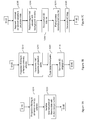
- FIGURE 6A the method for the generation of the 3D x-ray coronary artery image representation S130 is presented.
- the projection data is filtered S210 to enhance the coronary arteries and reduce the anatomic background using at least one of morphological filtering, multi-scale vesselness filtering and vessel segmentation, one or more combinations of these methods, or other known filtering methods.
- the filtered data is reconstructed S220 using in iterative reconstruction algorithm adapted for the limited number projection available and the laterally offset detector geometry.
- the reconstruction can also incorporate motion estimate and compensation to correct for cardiac motion or other residual motion.
- the method for the generation of the 2D planar coronary artery angiograms S140 is presented.
- the projection data is filtered S240 to enhance the coronary arteries.
- the captured field of view is truncated, e.g. coronary artery tree may be truncated, because the offset-detector geometry captures a little over half of the FOV. Therefore, a second projection acquired in the same cardiac motion state as the first is determined S250 such that the difference between the projection angles of the first and second projection is as close to 180° degrees as possible.
- the CT reconstruction processor 34 fuses the two projections S260 resulting in a composite or fused 2D angiogram S270 for the two given projection angles.
- the CT reconstruction processor 34 removes the contrast enhancement from the projections. It should be noted that the ECG signal may or may not be used in the generation of the AC map. To remove the contrast enhancement, the CT reconstruction processor 34 segments the contrast enhanced vessels S280 in the projection data, in the 2D planar angiograms generated in step S140, or in reconstructed image data using known methods and replaces the segmented regions with a background intensity S290.
- a 3D reconstruction is performed S300 to generate a 3D volume using a filtered backprojection or iterative algorithm which takes into account the laterally offset flat panel detector geometry.
- the generated 3D volume is post-processed S310 for noise removal, truncation correction, contrast medium reduction, or resolution adaptation like down-sampling.
- AC map is generated S320 from the processed 3D reconstruction volume.
- a computer readable medium having embodied thereon a computer program or instructions for controlling a processor for performing the cardiac imaging method of FIGURES 6 and FIGURES 7A-7C is provided.
Landscapes
- Health & Medical Sciences (AREA)
- Life Sciences & Earth Sciences (AREA)
- Engineering & Computer Science (AREA)
- Medical Informatics (AREA)
- Physics & Mathematics (AREA)
- General Health & Medical Sciences (AREA)
- Heart & Thoracic Surgery (AREA)
- Nuclear Medicine, Radiotherapy & Molecular Imaging (AREA)
- Optics & Photonics (AREA)
- Pathology (AREA)
- Radiology & Medical Imaging (AREA)
- Biomedical Technology (AREA)
- High Energy & Nuclear Physics (AREA)
- Molecular Biology (AREA)
- Surgery (AREA)
- Animal Behavior & Ethology (AREA)
- Biophysics (AREA)
- Public Health (AREA)
- Veterinary Medicine (AREA)
- Theoretical Computer Science (AREA)
- Computer Vision & Pattern Recognition (AREA)
- Dentistry (AREA)
- Oral & Maxillofacial Surgery (AREA)
- General Physics & Mathematics (AREA)
- Pulmonology (AREA)
- Vascular Medicine (AREA)
- Mathematical Analysis (AREA)
- Algebra (AREA)
- Physiology (AREA)
- Mathematical Optimization (AREA)
- Mathematical Physics (AREA)
- Pure & Applied Mathematics (AREA)
- Cardiology (AREA)
- Apparatus For Radiation Diagnosis (AREA)
- Nuclear Medicine (AREA)
Applications Claiming Priority (2)
| Application Number | Priority Date | Filing Date | Title |
|---|---|---|---|
| US201161453565P | 2011-03-17 | 2011-03-17 | |
| PCT/IB2012/051183 WO2012123896A2 (en) | 2011-03-17 | 2012-03-13 | Multiple modality cardiac imaging |
Publications (2)
| Publication Number | Publication Date |
|---|---|
| EP2685899A2 EP2685899A2 (en) | 2014-01-22 |
| EP2685899B1 true EP2685899B1 (en) | 2015-05-20 |
Family
ID=45937473
Family Applications (1)
| Application Number | Title | Priority Date | Filing Date |
|---|---|---|---|
| EP20120713340 Not-in-force EP2685899B1 (en) | 2011-03-17 | 2012-03-13 | Multiple modality cardiac imaging |
Country Status (6)
Families Citing this family (35)
| Publication number | Priority date | Publication date | Assignee | Title |
|---|---|---|---|---|
| DE102011083629A1 (de) * | 2011-09-28 | 2013-03-28 | Siemens Aktiengesellschaft | Bestimmung von potentiellen Perfusionsdefekten |
| EP2748798B1 (en) * | 2011-12-13 | 2018-04-11 | Koninklijke Philips N.V. | Automatic determination of regularization factor for iterative image reconstruction with regularization and/or image de-noising |
| DE102012205711B4 (de) * | 2012-04-05 | 2023-08-31 | Siemens Healthcare Gmbh | Verfahren zum Betreiben eines bildgebenden Diagnosegerätes sowie medizinisches bildgebendes System |
| NL2009981C2 (en) * | 2012-12-13 | 2014-06-16 | Umc Utrecht Holding Bv | A device and method for radiographic and nuclear imaging of an object. |
| EP2760028B1 (en) * | 2013-01-23 | 2018-12-12 | Samsung Electronics Co., Ltd | Radiation generator |
| JP2016515019A (ja) * | 2013-03-15 | 2016-05-26 | セノ メディカル インストルメンツ,インク. | 診断ベクトル分類サポートのためのシステムおよび方法 |
| BR112016001845A2 (pt) * | 2013-07-31 | 2017-08-01 | Koninklijke Philips Nv | aparelho para reconstrução de imagem de tomografia computadorizada de um objeto, método para processamento de imagens, elemento de programa de computador para controlar um aparelho, e mídia legível por computador |
| DE102014201134B4 (de) | 2014-01-22 | 2017-04-06 | Siemens Healthcare Gmbh | Verfahren und Vorrichtung zur Erzeugung eines 2-D-Projektionsbildes eines Gefäßsystems nebst korrespondierenden Gegenständen |
| JP6553099B2 (ja) * | 2014-06-30 | 2019-07-31 | コーニンクレッカ フィリップス エヌ ヴェKoninklijke Philips N.V. | 血流予備量比値を算出するための機器 |
| EP3192320A1 (en) * | 2014-09-10 | 2017-07-19 | Telefonaktiebolaget LM Ericsson (publ) | Radio access node, communication terminal and methods performed therein |
| CN107111875B (zh) * | 2014-12-09 | 2021-10-08 | 皇家飞利浦有限公司 | 用于多模态自动配准的反馈 |
| WO2016120869A1 (en) * | 2015-01-26 | 2016-08-04 | Biosensors International Group, Ltd. | Systems and methods for medical image registration |
| KR101812659B1 (ko) | 2015-09-09 | 2017-12-27 | 삼성전자주식회사 | 단층 촬영 장치 및 그에 따른 단층 영상 복원 방법 |
| DE102015219622A1 (de) * | 2015-10-09 | 2017-04-13 | Siemens Healthcare Gmbh | Rekonstruktion einer Abbildung anhand einer oder mehrerer Bildgebungsmodalitäten |
| US20180211423A1 (en) * | 2015-10-28 | 2018-07-26 | Koninklijke Philips N.V. | Computed tomography image generation apparatus |
| US10022101B2 (en) * | 2016-02-29 | 2018-07-17 | General Electric Company | X-ray/intravascular imaging colocation method and system |
| US10765329B2 (en) | 2016-05-02 | 2020-09-08 | Topera, Inc. | System and method to define an aggregated stability map of a rotational source over a plurality of time intervals associated with a biological rhythm disorder |
| CN105997125B (zh) * | 2016-06-15 | 2021-09-17 | 刘丽 | 多针孔单光子spect心肌血流绝对定量方法与用途 |
| US9965875B2 (en) * | 2016-06-21 | 2018-05-08 | Carestream Health, Inc. | Virtual projection image method |
| DE102016215976A1 (de) * | 2016-08-25 | 2018-03-01 | Siemens Healthcare Gmbh | Ermittelung einer klinischen Kenngröße mit einer Kombination unterschiedlicher Aufnahmemodalitäten |
| US10395353B2 (en) * | 2016-08-31 | 2019-08-27 | Siemens Medical Solutions Usa, Inc. | Model-based scatter in multi-modality multi-energy SPECT reconstruction |
| JP7098356B2 (ja) * | 2017-03-09 | 2022-07-11 | ゼネラル・エレクトリック・カンパニイ | Ct画像の色の視覚化のためのシステムおよび方法 |
| JP2018153297A (ja) * | 2017-03-16 | 2018-10-04 | コニカミノルタ株式会社 | X線動画像処理装置 |
| EP3378398A1 (en) * | 2017-03-24 | 2018-09-26 | Koninklijke Philips N.V. | Myocardial ct perfusion image synthesis |
| CN107610095A (zh) * | 2017-08-04 | 2018-01-19 | 南京邮电大学 | 基于图像融合的心脏ct冠脉全自动分割方法 |
| US11653888B2 (en) * | 2017-10-03 | 2023-05-23 | Shimadzu Corporation | Radiographic imaging apparatus |
| US10789738B2 (en) * | 2017-11-03 | 2020-09-29 | The University Of Chicago | Method and apparatus to reduce artifacts in a computed-tomography (CT) image by iterative reconstruction (IR) using a cost function with a de-emphasis operator |
| DE102018210429A1 (de) * | 2018-06-26 | 2020-01-02 | Siemens Healthcare Gmbh | Verfahren zur Darstellung eines Untersuchungsbereiches mit einer Feinstruktur |
| CN109646035B (zh) * | 2019-01-04 | 2022-04-22 | 北京永新医疗设备有限公司 | 骨断层图像重建方法及系统 |
| US11510642B2 (en) * | 2019-02-06 | 2022-11-29 | William E. Butler | Spatiotemporal reconstruction in higher dimensions of a moving vascular pulse wave from a plurality of lower dimensional angiographic projections |
| US12048575B2 (en) * | 2020-03-10 | 2024-07-30 | GE Precision Healthcare LLC | Systems and methods for registration of angiographic projections with computed tomographic data |
| CN111798533B (zh) * | 2020-07-15 | 2024-09-13 | 成都永新医疗设备有限公司 | 一种多针孔准直器定量重建方法及设备 |
| EP4238500A1 (en) * | 2022-03-02 | 2023-09-06 | Koninklijke Philips N.V. | Measurement of blood flow parameters |
| WO2025061493A1 (en) * | 2023-09-18 | 2025-03-27 | Koninklijke Philips N.V. | Providing a projection image of a vascular region |
| EP4524890A1 (en) * | 2023-09-18 | 2025-03-19 | Koninklijke Philips N.V. | Providing a projection image of a vascular region |
Family Cites Families (24)
| Publication number | Priority date | Publication date | Assignee | Title |
|---|---|---|---|---|
| JP3597918B2 (ja) * | 1995-09-11 | 2004-12-08 | 株式会社日立メディコ | X線ct装置 |
| US6310968B1 (en) * | 1998-11-24 | 2001-10-30 | Picker International, Inc. | Source-assisted attenuation correction for emission computed tomography |
| US20030128801A1 (en) * | 2002-01-07 | 2003-07-10 | Multi-Dimensional Imaging, Inc. | Multi-modality apparatus for dynamic anatomical, physiological and molecular imaging |
| JP4928739B2 (ja) * | 2004-06-25 | 2012-05-09 | 株式会社東芝 | X線診断装置及びx線撮像方法 |
| US7348564B2 (en) * | 2005-12-12 | 2008-03-25 | General Electric Company | Multi modality imaging methods and apparatus |
| DE102006002895B3 (de) * | 2006-01-20 | 2007-07-19 | Siemens Ag | Verfahren zur Erzeugung von Kardio-CT-Darstellungen unter Applikation eines Kontrastmittels und Mehr-Röhren-CT-System zur Durchführung dieses Verfahrens |
| JP2009525780A (ja) * | 2006-02-03 | 2009-07-16 | コーニンクレッカ フィリップス エレクトロニクス エヌ ヴィ | Ctベースの減衰マップを作成するときの異質対象物の明示 |
| DE102006019919B4 (de) * | 2006-04-28 | 2008-01-31 | Siemens Ag | Verfahren zur Aufnahme von Cardio-Röntgen-CT-Aufnahmen und Cardio-CT-System |
| US7813783B2 (en) * | 2006-11-02 | 2010-10-12 | General Electric Company | Methods and systems for attenuation correction in medical imaging |
| DE102006056884A1 (de) * | 2006-12-01 | 2008-06-05 | Siemens Ag | Verfahren und CT-System zur Durchführung einer Cardio-CT-Untersuchung eines Patienten |
| EP1959397B1 (en) * | 2007-02-19 | 2019-08-07 | Wisconsin Alumni Research Foundation | Iterative HYPR medical image reconstruction |
| DE102007046514A1 (de) * | 2007-09-28 | 2009-04-23 | Siemens Ag | Verfahren zur Erkennung und Markierung von Kontrastmittel in Blutgefäßen der Lunge mit Hilfe einer CT-Untersuchung und Bildauswerteeinheit eines CT-Systems |
| DE102007051548B4 (de) * | 2007-10-29 | 2009-12-10 | Siemens Ag | Verfahren zur Messung der Herzperfusion in einem Patienten und CT-System zur Durchführung dieses Verfahrens |
| US8098916B2 (en) * | 2007-10-30 | 2012-01-17 | General Electric Company | System and method for image-based attenuation correction of PET/SPECT images |
| EP2217147B1 (en) * | 2007-11-06 | 2012-06-27 | Koninklijke Philips Electronics N.V. | Nuclear medicine spect-ct machine with integrated asymmetric flat panel cone-beam ct and spect system |
| US8472688B2 (en) * | 2008-04-17 | 2013-06-25 | Wisconsin Alumni Research Foundation | Method for image reconstruction employing sparsity-constrained iterative correction |
| CN102265307B (zh) * | 2008-09-17 | 2014-10-22 | 皇家飞利浦电子股份有限公司 | 混合式核/mr成像中使用透射数据的mr分割 |
| WO2010084389A1 (en) * | 2009-01-21 | 2010-07-29 | Koninklijke Philips Electronics N.V. | Method and apparatus for large field of view imaging and detection and compensation of motion artifacts |
| DE102009014723B4 (de) * | 2009-03-25 | 2012-10-25 | Siemens Aktiengesellschaft | Kontrastabhängige Regularisierungsstärke bei der iterativen Rekonstruktion von CT-Bildern |
| DE102009036232A1 (de) * | 2009-08-05 | 2011-02-17 | Siemens Aktiengesellschaft | CT-Bildrekonstruktion für eine verbesserte Zeitauflösung in der Cardio-CT |
| JP2011067333A (ja) * | 2009-09-25 | 2011-04-07 | Fujifilm Corp | 放射線画像撮影装置及び撮影制御装置 |
| DE102009051384A1 (de) * | 2009-10-30 | 2011-05-12 | Friedrich-Alexander-Universität Erlangen-Nürnberg | Strahlaufhärtungskorrektur für CT-Perfusionsmessungen |
| US8971493B2 (en) * | 2010-09-08 | 2015-03-03 | Siemens Medical Solutions Usa, Inc. | System for image scanning and acquisition with low-dose radiation |
| RU2595808C2 (ru) * | 2011-03-07 | 2016-08-27 | Конинклейке Филипс Н.В. | Мр-сегментирование с использованием радионуклидных эмиссионных данных в смешанном радионуклидном/мр формировании изображения |
-
2012
- 2012-03-13 JP JP2013558550A patent/JP5872593B2/ja not_active Expired - Fee Related
- 2012-03-13 EP EP20120713340 patent/EP2685899B1/en not_active Not-in-force
- 2012-03-13 WO PCT/IB2012/051183 patent/WO2012123896A2/en active Application Filing
- 2012-03-13 CN CN2012800137639A patent/CN103458790A/zh active Pending
- 2012-03-13 US US14/005,569 patent/US20140003688A1/en not_active Abandoned
- 2012-03-13 RU RU2013146328/14A patent/RU2013146328A/ru not_active Application Discontinuation
Also Published As
| Publication number | Publication date |
|---|---|
| US20140003688A1 (en) | 2014-01-02 |
| WO2012123896A2 (en) | 2012-09-20 |
| WO2012123896A3 (en) | 2012-11-15 |
| CN103458790A (zh) | 2013-12-18 |
| JP5872593B2 (ja) | 2016-03-01 |
| RU2013146328A (ru) | 2015-04-27 |
| EP2685899A2 (en) | 2014-01-22 |
| JP2014517713A (ja) | 2014-07-24 |
Similar Documents
| Publication | Publication Date | Title |
|---|---|---|
| EP2685899B1 (en) | Multiple modality cardiac imaging | |
| Hyafil et al. | EANM procedural guidelines for myocardial perfusion scintigraphy using cardiac-centered gamma cameras | |
| EP2668639B1 (en) | Truncation compensation for iterative cone-beam ct reconstruction for spect/ct systems | |
| US8957894B2 (en) | System and method for four dimensional angiography and fluoroscopy | |
| US9001963B2 (en) | Method and apparatus for generating computed tomography images with offset detector geometries | |
| US8682415B2 (en) | Method and system for generating a modified 4D volume visualization | |
| US8811707B2 (en) | System and method for distributed processing of tomographic images | |
| JP5085031B2 (ja) | X線アンギオ撮影装置 | |
| US20140142423A1 (en) | System and method of time-resolved, three-dimensional angiography | |
| CN102335004B (zh) | 用于进行血管造影检查的方法和计算机断层造影设备 | |
| US8718347B2 (en) | Image display apparatus and X-ray diagnosis apparatus | |
| EP2502204A1 (en) | Motion correction in radiation therapy | |
| WO2007072286A2 (en) | Method for movement compensation of image data | |
| US8855391B2 (en) | Operating method for an imaging system for the time-resolved mapping of an iteratively moving examination object | |
| KR20170105876A (ko) | 단층 촬영 장치 및 그에 따른 단층 영상 재구성 방법 | |
| US10052078B2 (en) | Segmentation of moving structure in image data | |
| US20120087466A1 (en) | X-ray Image Recording Method | |
| Fahrig et al. | 14 C-arm CT in the interventional suite: Current status and future directions | |
| US20250232865A1 (en) | Systems and methods for image registration |
Legal Events
| Date | Code | Title | Description |
|---|---|---|---|
| PUAI | Public reference made under article 153(3) epc to a published international application that has entered the european phase |
Free format text: ORIGINAL CODE: 0009012 |
|
| 17P | Request for examination filed |
Effective date: 20131017 |
|
| AK | Designated contracting states |
Kind code of ref document: A2 Designated state(s): AL AT BE BG CH CY CZ DE DK EE ES FI FR GB GR HR HU IE IS IT LI LT LU LV MC MK MT NL NO PL PT RO RS SE SI SK SM TR |
|
| DAX | Request for extension of the european patent (deleted) | ||
| GRAP | Despatch of communication of intention to grant a patent |
Free format text: ORIGINAL CODE: EPIDOSNIGR1 |
|
| INTG | Intention to grant announced |
Effective date: 20140813 |
|
| GRAP | Despatch of communication of intention to grant a patent |
Free format text: ORIGINAL CODE: EPIDOSNIGR1 |
|
| INTG | Intention to grant announced |
Effective date: 20141219 |
|
| GRAS | Grant fee paid |
Free format text: ORIGINAL CODE: EPIDOSNIGR3 |
|
| GRAA | (expected) grant |
Free format text: ORIGINAL CODE: 0009210 |
|
| AK | Designated contracting states |
Kind code of ref document: B1 Designated state(s): AL AT BE BG CH CY CZ DE DK EE ES FI FR GB GR HR HU IE IS IT LI LT LU LV MC MK MT NL NO PL PT RO RS SE SI SK SM TR |
|
| REG | Reference to a national code |
Ref country code: GB Ref legal event code: FG4D |
|
| REG | Reference to a national code |
Ref country code: CH Ref legal event code: EP |
|
| REG | Reference to a national code |
Ref country code: AT Ref legal event code: REF Ref document number: 727305 Country of ref document: AT Kind code of ref document: T Effective date: 20150615 |
|
| REG | Reference to a national code |
Ref country code: IE Ref legal event code: FG4D |
|
| REG | Reference to a national code |
Ref country code: DE Ref legal event code: R096 Ref document number: 602012007424 Country of ref document: DE |
|
| REG | Reference to a national code |
Ref country code: AT Ref legal event code: MK05 Ref document number: 727305 Country of ref document: AT Kind code of ref document: T Effective date: 20150520 |
|
| REG | Reference to a national code |
Ref country code: LT Ref legal event code: MG4D |
|
| REG | Reference to a national code |
Ref country code: NL Ref legal event code: MP Effective date: 20150520 |
|
| PG25 | Lapsed in a contracting state [announced via postgrant information from national office to epo] |
Ref country code: NO Free format text: LAPSE BECAUSE OF FAILURE TO SUBMIT A TRANSLATION OF THE DESCRIPTION OR TO PAY THE FEE WITHIN THE PRESCRIBED TIME-LIMIT Effective date: 20150820 Ref country code: PT Free format text: LAPSE BECAUSE OF FAILURE TO SUBMIT A TRANSLATION OF THE DESCRIPTION OR TO PAY THE FEE WITHIN THE PRESCRIBED TIME-LIMIT Effective date: 20150921 Ref country code: ES Free format text: LAPSE BECAUSE OF FAILURE TO SUBMIT A TRANSLATION OF THE DESCRIPTION OR TO PAY THE FEE WITHIN THE PRESCRIBED TIME-LIMIT Effective date: 20150520 Ref country code: LT Free format text: LAPSE BECAUSE OF FAILURE TO SUBMIT A TRANSLATION OF THE DESCRIPTION OR TO PAY THE FEE WITHIN THE PRESCRIBED TIME-LIMIT Effective date: 20150520 Ref country code: HR Free format text: LAPSE BECAUSE OF FAILURE TO SUBMIT A TRANSLATION OF THE DESCRIPTION OR TO PAY THE FEE WITHIN THE PRESCRIBED TIME-LIMIT Effective date: 20150520 Ref country code: FI Free format text: LAPSE BECAUSE OF FAILURE TO SUBMIT A TRANSLATION OF THE DESCRIPTION OR TO PAY THE FEE WITHIN THE PRESCRIBED TIME-LIMIT Effective date: 20150520 |
|
| PG25 | Lapsed in a contracting state [announced via postgrant information from national office to epo] |
Ref country code: GR Free format text: LAPSE BECAUSE OF FAILURE TO SUBMIT A TRANSLATION OF THE DESCRIPTION OR TO PAY THE FEE WITHIN THE PRESCRIBED TIME-LIMIT Effective date: 20150821 Ref country code: RS Free format text: LAPSE BECAUSE OF FAILURE TO SUBMIT A TRANSLATION OF THE DESCRIPTION OR TO PAY THE FEE WITHIN THE PRESCRIBED TIME-LIMIT Effective date: 20150520 Ref country code: AT Free format text: LAPSE BECAUSE OF FAILURE TO SUBMIT A TRANSLATION OF THE DESCRIPTION OR TO PAY THE FEE WITHIN THE PRESCRIBED TIME-LIMIT Effective date: 20150520 Ref country code: BG Free format text: LAPSE BECAUSE OF FAILURE TO SUBMIT A TRANSLATION OF THE DESCRIPTION OR TO PAY THE FEE WITHIN THE PRESCRIBED TIME-LIMIT Effective date: 20150820 Ref country code: LV Free format text: LAPSE BECAUSE OF FAILURE TO SUBMIT A TRANSLATION OF THE DESCRIPTION OR TO PAY THE FEE WITHIN THE PRESCRIBED TIME-LIMIT Effective date: 20150520 Ref country code: IS Free format text: LAPSE BECAUSE OF FAILURE TO SUBMIT A TRANSLATION OF THE DESCRIPTION OR TO PAY THE FEE WITHIN THE PRESCRIBED TIME-LIMIT Effective date: 20150920 |
|
| PG25 | Lapsed in a contracting state [announced via postgrant information from national office to epo] |
Ref country code: EE Free format text: LAPSE BECAUSE OF FAILURE TO SUBMIT A TRANSLATION OF THE DESCRIPTION OR TO PAY THE FEE WITHIN THE PRESCRIBED TIME-LIMIT Effective date: 20150520 Ref country code: DK Free format text: LAPSE BECAUSE OF FAILURE TO SUBMIT A TRANSLATION OF THE DESCRIPTION OR TO PAY THE FEE WITHIN THE PRESCRIBED TIME-LIMIT Effective date: 20150520 |
|
| REG | Reference to a national code |
Ref country code: DE Ref legal event code: R097 Ref document number: 602012007424 Country of ref document: DE |
|
| PG25 | Lapsed in a contracting state [announced via postgrant information from national office to epo] |
Ref country code: PL Free format text: LAPSE BECAUSE OF FAILURE TO SUBMIT A TRANSLATION OF THE DESCRIPTION OR TO PAY THE FEE WITHIN THE PRESCRIBED TIME-LIMIT Effective date: 20150520 Ref country code: RO Free format text: LAPSE BECAUSE OF NON-PAYMENT OF DUE FEES Effective date: 20150520 Ref country code: SK Free format text: LAPSE BECAUSE OF FAILURE TO SUBMIT A TRANSLATION OF THE DESCRIPTION OR TO PAY THE FEE WITHIN THE PRESCRIBED TIME-LIMIT Effective date: 20150520 Ref country code: CZ Free format text: LAPSE BECAUSE OF FAILURE TO SUBMIT A TRANSLATION OF THE DESCRIPTION OR TO PAY THE FEE WITHIN THE PRESCRIBED TIME-LIMIT Effective date: 20150520 |
|
| PLBE | No opposition filed within time limit |
Free format text: ORIGINAL CODE: 0009261 |
|
| STAA | Information on the status of an ep patent application or granted ep patent |
Free format text: STATUS: NO OPPOSITION FILED WITHIN TIME LIMIT |
|
| 26N | No opposition filed |
Effective date: 20160223 |
|
| PG25 | Lapsed in a contracting state [announced via postgrant information from national office to epo] |
Ref country code: IT Free format text: LAPSE BECAUSE OF FAILURE TO SUBMIT A TRANSLATION OF THE DESCRIPTION OR TO PAY THE FEE WITHIN THE PRESCRIBED TIME-LIMIT Effective date: 20150520 |
|
| PG25 | Lapsed in a contracting state [announced via postgrant information from national office to epo] |
Ref country code: SI Free format text: LAPSE BECAUSE OF FAILURE TO SUBMIT A TRANSLATION OF THE DESCRIPTION OR TO PAY THE FEE WITHIN THE PRESCRIBED TIME-LIMIT Effective date: 20150520 |
|
| PG25 | Lapsed in a contracting state [announced via postgrant information from national office to epo] |
Ref country code: BE Free format text: LAPSE BECAUSE OF FAILURE TO SUBMIT A TRANSLATION OF THE DESCRIPTION OR TO PAY THE FEE WITHIN THE PRESCRIBED TIME-LIMIT Effective date: 20150520 |
|
| REG | Reference to a national code |
Ref country code: DE Ref legal event code: R119 Ref document number: 602012007424 Country of ref document: DE |
|
| PG25 | Lapsed in a contracting state [announced via postgrant information from national office to epo] |
Ref country code: LU Free format text: LAPSE BECAUSE OF FAILURE TO SUBMIT A TRANSLATION OF THE DESCRIPTION OR TO PAY THE FEE WITHIN THE PRESCRIBED TIME-LIMIT Effective date: 20160313 Ref country code: MC Free format text: LAPSE BECAUSE OF FAILURE TO SUBMIT A TRANSLATION OF THE DESCRIPTION OR TO PAY THE FEE WITHIN THE PRESCRIBED TIME-LIMIT Effective date: 20150520 |
|
| REG | Reference to a national code |
Ref country code: CH Ref legal event code: PL |
|
| GBPC | Gb: european patent ceased through non-payment of renewal fee |
Effective date: 20160313 |
|
| REG | Reference to a national code |
Ref country code: IE Ref legal event code: MM4A |
|
| REG | Reference to a national code |
Ref country code: FR Ref legal event code: ST Effective date: 20161130 |
|
| PG25 | Lapsed in a contracting state [announced via postgrant information from national office to epo] |
Ref country code: FR Free format text: LAPSE BECAUSE OF NON-PAYMENT OF DUE FEES Effective date: 20160331 Ref country code: IE Free format text: LAPSE BECAUSE OF NON-PAYMENT OF DUE FEES Effective date: 20160313 Ref country code: DE Free format text: LAPSE BECAUSE OF NON-PAYMENT OF DUE FEES Effective date: 20161001 Ref country code: LI Free format text: LAPSE BECAUSE OF NON-PAYMENT OF DUE FEES Effective date: 20160331 Ref country code: CH Free format text: LAPSE BECAUSE OF NON-PAYMENT OF DUE FEES Effective date: 20160331 Ref country code: GB Free format text: LAPSE BECAUSE OF NON-PAYMENT OF DUE FEES Effective date: 20160313 |
|
| PG25 | Lapsed in a contracting state [announced via postgrant information from national office to epo] |
Ref country code: SE Free format text: LAPSE BECAUSE OF FAILURE TO SUBMIT A TRANSLATION OF THE DESCRIPTION OR TO PAY THE FEE WITHIN THE PRESCRIBED TIME-LIMIT Effective date: 20150520 Ref country code: NL Free format text: LAPSE BECAUSE OF FAILURE TO SUBMIT A TRANSLATION OF THE DESCRIPTION OR TO PAY THE FEE WITHIN THE PRESCRIBED TIME-LIMIT Effective date: 20150520 |
|
| PG25 | Lapsed in a contracting state [announced via postgrant information from national office to epo] |
Ref country code: MT Free format text: LAPSE BECAUSE OF FAILURE TO SUBMIT A TRANSLATION OF THE DESCRIPTION OR TO PAY THE FEE WITHIN THE PRESCRIBED TIME-LIMIT Effective date: 20150520 |
|
| PG25 | Lapsed in a contracting state [announced via postgrant information from national office to epo] |
Ref country code: HU Free format text: LAPSE BECAUSE OF FAILURE TO SUBMIT A TRANSLATION OF THE DESCRIPTION OR TO PAY THE FEE WITHIN THE PRESCRIBED TIME-LIMIT; INVALID AB INITIO Effective date: 20120313 Ref country code: SM Free format text: LAPSE BECAUSE OF FAILURE TO SUBMIT A TRANSLATION OF THE DESCRIPTION OR TO PAY THE FEE WITHIN THE PRESCRIBED TIME-LIMIT Effective date: 20150520 Ref country code: CY Free format text: LAPSE BECAUSE OF FAILURE TO SUBMIT A TRANSLATION OF THE DESCRIPTION OR TO PAY THE FEE WITHIN THE PRESCRIBED TIME-LIMIT Effective date: 20150520 |
|
| PG25 | Lapsed in a contracting state [announced via postgrant information from national office to epo] |
Ref country code: MT Free format text: LAPSE BECAUSE OF FAILURE TO SUBMIT A TRANSLATION OF THE DESCRIPTION OR TO PAY THE FEE WITHIN THE PRESCRIBED TIME-LIMIT Effective date: 20160331 Ref country code: TR Free format text: LAPSE BECAUSE OF FAILURE TO SUBMIT A TRANSLATION OF THE DESCRIPTION OR TO PAY THE FEE WITHIN THE PRESCRIBED TIME-LIMIT Effective date: 20150520 Ref country code: MK Free format text: LAPSE BECAUSE OF FAILURE TO SUBMIT A TRANSLATION OF THE DESCRIPTION OR TO PAY THE FEE WITHIN THE PRESCRIBED TIME-LIMIT Effective date: 20150520 |
|
| PG25 | Lapsed in a contracting state [announced via postgrant information from national office to epo] |
Ref country code: AL Free format text: LAPSE BECAUSE OF FAILURE TO SUBMIT A TRANSLATION OF THE DESCRIPTION OR TO PAY THE FEE WITHIN THE PRESCRIBED TIME-LIMIT Effective date: 20150520 |