EP2685040A2 - Pretensioning component and working method for a window or a sliding window-door - Google Patents
Pretensioning component and working method for a window or a sliding window-door Download PDFInfo
- Publication number
- EP2685040A2 EP2685040A2 EP13176007.6A EP13176007A EP2685040A2 EP 2685040 A2 EP2685040 A2 EP 2685040A2 EP 13176007 A EP13176007 A EP 13176007A EP 2685040 A2 EP2685040 A2 EP 2685040A2
- Authority
- EP
- European Patent Office
- Prior art keywords
- wing
- biasing member
- frame
- power transmission
- arm
- Prior art date
- Legal status (The legal status is an assumption and is not a legal conclusion. Google has not performed a legal analysis and makes no representation as to the accuracy of the status listed.)
- Granted
Links
- 238000000034 method Methods 0.000 title claims abstract description 8
- 230000005540 biological transmission Effects 0.000 claims abstract description 21
- 230000009467 reduction Effects 0.000 claims description 4
- 230000036316 preload Effects 0.000 claims description 2
- 238000010276 construction Methods 0.000 description 4
- 230000009471 action Effects 0.000 description 3
- 238000006073 displacement reaction Methods 0.000 description 3
- 230000000694 effects Effects 0.000 description 3
- 230000008569 process Effects 0.000 description 3
- 230000006978 adaptation Effects 0.000 description 2
- 230000006835 compression Effects 0.000 description 2
- 238000007906 compression Methods 0.000 description 2
- 230000001419 dependent effect Effects 0.000 description 2
- 239000011521 glass Substances 0.000 description 2
- 230000005484 gravity Effects 0.000 description 2
- 229910000831 Steel Inorganic materials 0.000 description 1
- 239000006096 absorbing agent Substances 0.000 description 1
- 230000015572 biosynthetic process Effects 0.000 description 1
- 230000008859 change Effects 0.000 description 1
- 238000009434 installation Methods 0.000 description 1
- 238000009413 insulation Methods 0.000 description 1
- 230000010354 integration Effects 0.000 description 1
- 239000000463 material Substances 0.000 description 1
- 230000035939 shock Effects 0.000 description 1
- 239000010959 steel Substances 0.000 description 1
- 230000007704 transition Effects 0.000 description 1
Images

Classifications
-
- E—FIXED CONSTRUCTIONS
- E05—LOCKS; KEYS; WINDOW OR DOOR FITTINGS; SAFES
- E05D—HINGES OR SUSPENSION DEVICES FOR DOORS, WINDOWS OR WINGS
- E05D15/00—Suspension arrangements for wings
- E05D15/06—Suspension arrangements for wings for wings sliding horizontally more or less in their own plane
- E05D15/10—Suspension arrangements for wings for wings sliding horizontally more or less in their own plane movable out of one plane into a second parallel plane
- E05D15/1005—Suspension arrangements for wings for wings sliding horizontally more or less in their own plane movable out of one plane into a second parallel plane the wing being supported on arms movable in horizontal planes
- E05D15/1013—Suspension arrangements for wings for wings sliding horizontally more or less in their own plane movable out of one plane into a second parallel plane the wing being supported on arms movable in horizontal planes specially adapted for windows
-
- E—FIXED CONSTRUCTIONS
- E05—LOCKS; KEYS; WINDOW OR DOOR FITTINGS; SAFES
- E05Y—INDEXING SCHEME RELATING TO HINGES OR OTHER SUSPENSION DEVICES FOR DOORS, WINDOWS OR WINGS AND DEVICES FOR MOVING WINGS INTO OPEN OR CLOSED POSITION, CHECKS FOR WINGS AND WING FITTINGS NOT OTHERWISE PROVIDED FOR, CONCERNED WITH THE FUNCTIONING OF THE WING
- E05Y2201/00—Constructional elements; Accessories therefore
- E05Y2201/40—Motors; Magnets; Springs; Weights; Accessories therefore
- E05Y2201/404—Motors; Magnets; Springs; Weights; Accessories therefore characterised by the function
- E05Y2201/422—Motors; Magnets; Springs; Weights; Accessories therefore characterised by the function for opening
- E05Y2201/426—Motors; Magnets; Springs; Weights; Accessories therefore characterised by the function for opening for the initial opening movement
-
- E—FIXED CONSTRUCTIONS
- E05—LOCKS; KEYS; WINDOW OR DOOR FITTINGS; SAFES
- E05Y—INDEXING SCHEME RELATING TO HINGES OR OTHER SUSPENSION DEVICES FOR DOORS, WINDOWS OR WINGS AND DEVICES FOR MOVING WINGS INTO OPEN OR CLOSED POSITION, CHECKS FOR WINGS AND WING FITTINGS NOT OTHERWISE PROVIDED FOR, CONCERNED WITH THE FUNCTIONING OF THE WING
- E05Y2201/00—Constructional elements; Accessories therefore
- E05Y2201/40—Motors; Magnets; Springs; Weights; Accessories therefore
- E05Y2201/47—Springs; Spring tensioners
-
- E—FIXED CONSTRUCTIONS
- E05—LOCKS; KEYS; WINDOW OR DOOR FITTINGS; SAFES
- E05Y—INDEXING SCHEME RELATING TO HINGES OR OTHER SUSPENSION DEVICES FOR DOORS, WINDOWS OR WINGS AND DEVICES FOR MOVING WINGS INTO OPEN OR CLOSED POSITION, CHECKS FOR WINGS AND WING FITTINGS NOT OTHERWISE PROVIDED FOR, CONCERNED WITH THE FUNCTIONING OF THE WING
- E05Y2900/00—Application of doors, windows, wings or fittings thereof
- E05Y2900/10—Application of doors, windows, wings or fittings thereof for buildings or parts thereof
- E05Y2900/13—Application of doors, windows, wings or fittings thereof for buildings or parts thereof characterised by the type of wing
- E05Y2900/132—Doors
-
- E—FIXED CONSTRUCTIONS
- E05—LOCKS; KEYS; WINDOW OR DOOR FITTINGS; SAFES
- E05Y—INDEXING SCHEME RELATING TO HINGES OR OTHER SUSPENSION DEVICES FOR DOORS, WINDOWS OR WINGS AND DEVICES FOR MOVING WINGS INTO OPEN OR CLOSED POSITION, CHECKS FOR WINGS AND WING FITTINGS NOT OTHERWISE PROVIDED FOR, CONCERNED WITH THE FUNCTIONING OF THE WING
- E05Y2900/00—Application of doors, windows, wings or fittings thereof
- E05Y2900/10—Application of doors, windows, wings or fittings thereof for buildings or parts thereof
- E05Y2900/13—Application of doors, windows, wings or fittings thereof for buildings or parts thereof characterised by the type of wing
- E05Y2900/148—Windows
Definitions
- the disclosed and claimed invention relates generally to a window or patio door which includes at least one wing which can be opened by means of an actuator so as to provide an opening gap between the wing and a frame of the window or the French window. This as a method and as a device.
- An object of the invention is to improve the ease of use for a window and / or door with a view to opening a sash and maintaining an open position of the sash.
- a biasing member includes a first power transmission component engageable with a wing of the window and / or the door.
- the biasing member further comprises a second, with a frame of the window and / or the door brought into contact power transmission component (claim 1).
- the biasing member is provided with mechanically biased biasing means coupled to the first power transmission component and the second power transmission component and configured to cause a force acting in the direction of increasing an opening gap between the blade and the frame. This at least up to a predetermined width of the opening gap, which is predetermined by scissors of the fitting (claim 19).
- the biasing member according to the invention is thus designed so that due to the mechanically operated biasing means, a force is exerted which tends to support the opening of the wing.
- a substantial proportion of the force required for this purpose can be provided by the mechanically operated pretensioning device, resulting in a significantly lower expenditure of force on the part of the operator or an automatic opening system.
- the mechanically operated biasing device is a device in which energy that is released during an opening process due to the force acting, was stored by mechanical action on the biasing device when closing.
- no electrical drive components are required in order to provide the desired preload force when opening a wing of the window or the door.
- the biasing device is further formed to counteract this reduction in reducing the opening gap.
- this reduction in this way, a more stable position of the wing is ensured in the presence of an opening gap.
- there is no undesirable high resistance in closing the wing since typically the largest force of the biasing member occurring at the end of a closing operation is substantially substantially compensated by the previously received pulse of the often heavy blade.
- the first power transmission component comprises a first arm and the second power transmission component comprises a second arm of a scissors arrangement.
- the use of a scissors arrangement results in a very compact construction for the biasing member, since the individual arms of the scissor assembly can be provided as elongated components with a small thickness, so that attachment to the wing or the frame in conventional constructions is possible without major additional design measures.
- the arms of the scissor assembly can be of the same or different lengths, so that can be achieved without great effort to adapt to the existing conditions in the basic construction of windows and doors.
- the opening gap between the wing and the frame can thus be varied by generating and adjusting an opening angle of the scissor assembly, the two arms efficiently serving for power transmission.
- the arms can thus act at least as part of the first and second components for power transmission, wherein, if necessary, further mechanical components can be provided to actually contact the wing and / or the frame.
- the first arm and the second arm each have a first end region with a common axis of rotation formed therein.
- the entire length of the first and the second arm can be used to produce the largest possible opening gap at a predetermined opening angle between the first arm and the second arm.
- the corresponding axis of rotation can also be provided in a middle region of the arms.
- the first arm and / or the second arm are provided with a holding device, which ensures a permanent contact with the wing or the frame.
- the holding device is advantageously designed so that an assembly at a suitable position on the frame or on the wing is possible.
- suitable fastening means are provided which allow mounting on existing fitting components.
- the second end region of the first or the second arm is provided with a receptacle for attachment to a movement rail, in particular as a slide rail.
- a movement rail in particular as a slide rail.
- the pretensioning component is designed in the form of a fitting component of the sash of the window and / or the door and thus allows a space-saving installation at a suitable position of the sash or of the frame.
- the structure of the biasing member according to the invention in the form of a fitting component can be made so that integration into existing hardware components is possible, with no or only very minor structural changes in the design of existing types of construction of windows and doors are made.
- the biasing means comprises a spring element.
- Suitable components such as in the form of a leg spring, a tension spring, a compression spring and the like can be used, so that an efficient adaptation of the force-generating component in the pretensioner can be made depending on the structural requirements.
- the pretensioning device has a compressed gas volume, which is provided, for example, in the form of a shock absorber and the like. In this way, a desired adaptation to the structural requirements can be achieved efficiently, since a large number of corresponding gas springs is available.
- a spring element is provided and this is mounted in the direction of the axis of rotation of the scissor assembly in a space which is formed between the first arm and the second arm.
- the spring element is provided in the form of a leg spring, which is fastened to the first and the second arm with suitable fastening means.
- the wire guide the leg spring takes place in advantageous embodiments so that at an opening angle of zero, the maximum biasing force results, so that in particular the otherwise force-demanding opening operation in the Initial phase a strong supporting force effect is provided by the biasing member.
- a height of the biasing member is not greater than the height of a space between a sash and a compassionfalz or the height between an overlying frame-side guide rail (or receptacle) and a wing retaining rail (or recording) takes on the biasing member (claim 11).
- the biasing member without additional structural measures in windows and doors with otherwise known properties and dimensions integrate (and cover).
- a window and / or door device which comprises a frame and a wing with an actuator provided for opening the sash. Furthermore, a pretensioning component is provided in the window and / or door device according to the invention, as described above or also below, which develops a force effect between the frame and the wing.
- the biasing member is mounted in a variant on an upper portion of the frame or the wing.
- the biasing member is mounted to a vertical portion of the frame or wing. That is, the biasing member of the present invention can be disposed at an appropriate position on the vertical or horizontal portions so as to achieve efficient power development without requiring changes in the basic structure of the window and / or door apparatus.
- the biasing member is mounted in a space between the wing and frame.
- a pretensioning component advantageously in the form of a fitting component, which delivers an additional force to support the wing opening movement and, in the open state of the wing, assists this position by means of a pre-existing prestressing element.
- the closing forces on the wing, the fitting or the actuator do not increase or only slightly.
- the assembly of this component takes place in the form of an additional component, so that the respective standard fitting for the different window opening types is further used.
- the formation of the scissor arms can be designed so that a variety of connections to the wing / frame are possible.
- the possibility of inserting a scissor arm in a wing holding rail and the design of the second scissor arm, in the way that a movable piece, in particular coupled as a slider can be plugged opens the possibility that the scissor assembly can be moved laterally with the wing , In this way, a known and common operation of the parallel parking (tilt) sliding door much easier.
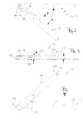
- FIG. 1 shows a perspective view of a window device 100, the frame 1 and at least one wing 2, which is movable with respect to the frame 1, has.
- the device 100 has an actuating device 3 (as a lever), by means of which a locking or unlocking of the wing 2 can take place in the closed position and can then be brought by a force of the wing 2 from a closed position to an open position, wherein an opening gap 2a between the frame 1 and the wing 2 results.
- actuating device 3 as a lever
- the window device 100 is a hinged window with parallel sliding wing 2, while in other embodiments also tilt windows, folding windows and the like are used.
- the device 100 is also referred to as a Door device or provided as a French door, since the biasing member 10 can be applied to a variety of different types of window devices and door devices.
- FIG. 1 the wing 2 is shown in an open position, in which by means of known fitting components 6, a mechanical guidance of the wing with respect to the frame 1 takes place.
- a biasing member 10 is provided which is formed so that one for reaching the in FIG. 1 shown opening gap 2a a force F is exerted during the opening operation. Further, the biasing member 10 further exerts a counteracting the reduction of the opening gap 2a force, also referred to as F from. This results in a more stable definition of the opening gap 2a and it is an undesirable change of the opening gap 2a toward the closed position in the absence of action of an operator substantially avoided.
- the biasing member 10 is provided in the form of a scissor assembly, in which a biasing means, which is described in detail below, is provided in the form of a spring or as a pneumatic-hydraulic component or the like, which the desired for the opening operation power assistance F provides.
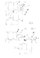
- FIG. 2 shows a plan view of the biasing member 10, which has a first arm 15 and a second arm 16 as a scissor assembly, which are connected to each other at respective end portions 15a, 16a by a common axis of rotation 14.
- the biasing member 10 further includes a biasing means 18, which is provided in the illustrated embodiment as a leg spring.
- the biasing device 18 is designed so that at least up to a certain opening angle ⁇ , the force F between the two arms 16 and 15 acts, which leads to an increase in the opening angle. Providing a spring for the biasing device 18 thus results in a force which is dependent on the size of the opening angle ⁇ and in the illustrated embodiment is greatest at an opening angle of zero.
- the arms 15, 16 are provided with different lengths, while in other embodiments they may be provided with the same length.
- the arms 15, 16 preferably have the dimensions of commonly used cover rail material, similar to steel strip, although other design variants depending on the available space are possible.
- FIG. 3 is a side view of the biasing member 10 and FIG. 4 a view from below.
- a height H which in turn is selected so that the biasing member 10 can be integrated in a desired manner in a window device or door device, without causing undesirable additional design measures to an existing structure are required.
- the scissor arms are thus spaced apart from each other, to receive in this intermediate space of the height Z, the biasing means in the form of a spring element, which is formed in this embodiment as a leg spring about the axis of rotation 14.
- a spring leg 18a is associated with the arm 15 and positively connected thereto, while a second spring leg 18b associated with the arm 16 and connected thereto, wherein this is done with suitable fasteners. Exemplary is in to FIG. 4 a fastener 19a is shown on the arm 16. Both connections result in a pair of scissors with internal leg spring.
- the opening angle ⁇ is only as large as the max. Opening angle of the relaxed spring allows. In this state, the biasing member 10 has no bias.
- the Drehachsseite 14 At the end portion 15a of the first arm 15 is the Drehachsseite 14 and at an opposite end portion 15b is a holding device as Fasteners 17 ( FIG. 3 ), z. B. in the form of a projecting receptacle, for example as riveted bolt, which can be inserted into a slider or wing frame.
- the second arm 16 is formed with its one pivot axis end 16a and with another end portion 16b so that receiving holes 16c are provided for fastening means 19b, such as clamping bolts, screws, which act as a clamping device when the arm 16 is dimensioned, that it can be inserted into an existing wing retaining rail and secured against displacement.
- fastening means 19b such as clamping bolts, screws
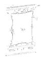
- FIG. 5 shows a side cross-sectional view in which the frame 1 and the wing 2 are in a closed position.
- the arm 16 is fastened by means of the fastening means 19b in a retaining rail 2b of the wing 2 and is thus in permanent contact with the wing 2.
- the arm 15 of the biasing member 10 is connected via the holding device 17 with a moving element as, for example, slider 20, which in turn is guided in a rail 1a on the frame 1.
- the biasing means 18 causes maximum force between the wing 2 and the frame 1 to assist or initiate an unlocking operation.
- FIG. 6 shows the frame 1 and the wing 2 in an open position, in which thus the arm 15 and the arm 16 include a non-zero opening angle with each other, as for example in the FIGS. 2 and 4 is shown.
- the biasing force 18 force F acts during the transition from the closed state to the open state caused by the biasing force 18 force F, which tends to increase the opening angle ⁇ further, unless the maximum opening angle is reached 2a, in which the biasing means 18 no further Pretension force exerts (and the scissors 6b limit this opening 2a a).
- the height H of the biasing member 10 - which is here essentially defined by the two arms 15 and 16 and the intermediate biasing device 18 - dimensioned so that it is not greater than the space BR (its height) between the wing. 2 (Top edge) and frame 1 (lower edge of slide rail 1a); the space under an overlying frame-side guide rail (or recording 1a) and the wing-holding rail 2b (its mounting point or its horizontal portion of the angle 2b). This is usually the top of the wing on which the angled support rail 2b is mounted.
- FIG. 7 is an exploded perspective view illustrating conventional standard fitting components, collectively designated 6, while the biasing member 10 is integrated at an upper position in cooperation with the standard fitting components 6 so that there are no additional design measures with respect to the otherwise predetermined one Structure of the window or the door are required.
- sliding members 6c of the standard fitting members 6 are shown together with corresponding standard opening shears 6b, which allow the generation of an opening gap 2a and a displacement of the wing, but high forces of the operator would be required.
- the biasing member 10 is disposed between the two Ausstellscheren 6b.
- a scissors assembly 10 is additionally provided, which provides the desired, biasing force F during the opening operation and also maintains a biasing force in the open position.
- biasing device 18 shown in the figures as a spring of the biasing member 10 is only an advantageous variant.
- biasing member 10 is placed outboard at the top of the frame / wing in a preferred embodiment, another positioning, e.g. B. on the side of / on the vertical profiles possible.
- Another possible mounting space can also be the distance br1 between the frame and sash (in the rebate), shown in FIG. 5 but without prestressing scissors 10 inserted there.
Abstract
Description
Die offenbarte und beanspruchte Erfindung betrifft allgemein ein Fenster oder eine Fenstertür, die mindestens einen Flügel, der mittels einer Betätigungseinrichtung so geöffnet werden kann, dass sich ein Öffnungsspalt zwischen dem Flügel und einem Rahmen des Fensters oder der Fenstertür ergibt, enthält. Dies als Verfahren und als Vorrichtung.The disclosed and claimed invention relates generally to a window or patio door which includes at least one wing which can be opened by means of an actuator so as to provide an opening gap between the wing and a frame of the window or the French window. This as a method and as a device.
Aufgrund gestiegener Anforderungen für Türen und Fenster, insbesondere im Hinblick auf eine ausgeprägte Dämmwirkung zur Reduzierung des Wärmeaustauschs und zur Verbesserung des Schallschutzes, werden zunehmend komplexe Konstruktionen für Türen und Fenster verwendet. Aus diesen Gründen weisen derartige hochwertige Bauelemente eine zunehmend größere Tiefe des Rahmenprofils und des Flügelprofils auf, so dass typischerweise auch das Gewicht insbesondere der Flügel aufgrund der zuvor genannten verbesserten Dämmeigenschaften und aufgrund der größeren Menge an Glasvolumen, etwa bei einem Drei-Scheiben-Glas, ansteigt.Due to increased requirements for doors and windows, in particular with regard to a pronounced insulating effect to reduce heat exchange and to improve sound insulation, increasingly complex designs for doors and windows are used. For these reasons, such high-quality components have an increasingly greater depth of the frame profile and the wing profile, so that typically also the weight in particular of the wing due to the aforementioned improved insulating properties and due to the larger amount of glass volume, such as a three-pane glass, increases.
In Verbindung mit einem weit außen liegenden Flügelschwerpunkt steigen daher auch die Bedienkräfte an, die zum Öffnen des Flügels an der Betätigungseinrichtung aufzubringen sind. Diese erhöhten Bedienkräfte können weiterhin zu einer erhöhten Belastung der vorhandenen Beschlagbauteile und gegebenenfalls auch zu einer Überlastung führen, da häufig die Beschlagbauteile aus Platzgründen nicht verstärkt ausgeführt werden können. Bei tiefen Profilen neigen insbesondere die Flügel zum selbsttätigen Zurückfallen in die geschlossene Position, so dass eine stabile Lage, etwa beim Lüften und dergleichen, typischerweise nur durch zusätzliche Maßnahmen erreicht werden kann.In conjunction with a far outward center of gravity of the wing therefore also increase the operating forces that are applied to open the wing on the actuator. These increased operating forces can continue to lead to an increased load on the existing hardware components and possibly also to an overload, since often the hardware components can not be made reinforced for reasons of space. In the case of deep profiles, in particular, the wings tend to automatically fall back into the closed position, so that a stable position, for example when ventilating and the like, can typically only be achieved by additional measures.
Eine Aufgabe der Erfindung ist es, den Bedienkomfort für ein Fenster und/oder eine Tür mit Blick auf das Öffnen eines Flügels und die Beibehaltung einer Offenstellung des Flügels zu verbessern. An object of the invention is to improve the ease of use for a window and / or door with a view to opening a sash and maintaining an open position of the sash.
Gemäß der beanspruchten Erfindung wird ein Vorspannbauteil bereitgestellt. Das Vorspannbauteil umfasst eine erste, mit einem Flügel des Fensters und/oder der Tür in Kontakt bringbare Kraftübertragungskomponente. Das Vorspannbauteil umfasst ferner eine zweite, mit einem Rahmen des Fensters und/oder der Tür in Kontakt bringbare Kraftübertragungskomponente (Anspruch 1).According to the claimed invention, a biasing member is provided. The biasing member includes a first power transmission component engageable with a wing of the window and / or the door. The biasing member further comprises a second, with a frame of the window and / or the door brought into contact power transmission component (claim 1).
Ferner ist das Vorspannbauteil mit einer mechanisch betriebenen Vorspanneinrichtung versehen, die mit der ersten Kraftübertragungskomponente und der zweiten Kraftübertragungskomponente gekoppelt und ausgebildet ist, eine in Richtung einer Vergrößerung eines Öffnungsspaltes zwischen dem Flügel und dem Rahmen wirkende Kraft hervorzurufen. Dies zumindest bis zu einer vorbestimmten Breite des Öffnungsspaltes, die von Scheren des Beschlags vorgegeben wird (Anspruch 19).Further, the biasing member is provided with mechanically biased biasing means coupled to the first power transmission component and the second power transmission component and configured to cause a force acting in the direction of increasing an opening gap between the blade and the frame. This at least up to a predetermined width of the opening gap, which is predetermined by scissors of the fitting (claim 19).
Das erfindungsgemäße Vorspannbauteil ist also so ausgebildet, dass aufgrund der mechanisch betriebenen Vorspanneinrichtung eine Kraft ausgeübt wird, die beim Öffnen des Flügels tendenziell unterstützend wirkt. Insbesondere beim Öffnungsvorgang kann ein wesentlicher Anteil der dazu erforderlichen Kraft von der mechanisch betriebenen Vorspanneinrichtung bereitgestellt werden, so dass sich ein deutlich geringerer Kraftaufwand für den Bediener oder auch ein automatisches Öffnungssystem ergibt.The biasing member according to the invention is thus designed so that due to the mechanically operated biasing means, a force is exerted which tends to support the opening of the wing. In particular, during the opening process, a substantial proportion of the force required for this purpose can be provided by the mechanically operated pretensioning device, resulting in a significantly lower expenditure of force on the part of the operator or an automatic opening system.
Die mechanisch betriebene Vorspanneinrichtung ist dabei eine Einrichtung, in der Energie, die bei einem Öffnungsvorgang aufgrund der wirkenden Kraft freigesetzt wird, durch mechanische Einwirkung auf die Vorspanneinrichtung beim Schließen gespeichert wurde. Es sind also insbesondere keine elektrischen Antriebskomponenten erforderlich, um die beim Öffnen eines Flügels des Fensters bzw. der Tür gewünschte Vorspannkraft bereitzustellen.The mechanically operated biasing device is a device in which energy that is released during an opening process due to the force acting, was stored by mechanical action on the biasing device when closing. In particular, no electrical drive components are required in order to provide the desired preload force when opening a wing of the window or the door.
Demzufolge ist in einer vorteilhaften Ausführungsform die Vorspanneinrichtung ferner ausgebildet, bei Verringerung des Öffnungsspaltes dieser Verringerung entgegenzuwirken. Auf diese Weise wird auch eine stabilere Lage des Flügels bei Vorhandensein eines Öffnungsspaltes gewährleistet. Andererseits ergibt sich jedoch kein unerwünscht hoher Widerstand beim Schließen des Flügels, da typischerweise die am Ende eines Schließvorgangs auftretende größte Kraft des Vorspannbauteils im Wesentlichen durch den zuvor aufgenommenen Impuls des häufig schweren Flügels im Wesentlichen kompensiert wird.Accordingly, in an advantageous embodiment, the biasing device is further formed to counteract this reduction in reducing the opening gap. In this way, a more stable position of the wing is ensured in the presence of an opening gap. On the other hand, however, there is no undesirable high resistance in closing the wing, since typically the largest force of the biasing member occurring at the end of a closing operation is substantially substantially compensated by the previously received pulse of the often heavy blade.
In einer weiteren vorteilhaften Ausführungsform umfasst die erste Kraftübertragungs-Komponente einen ersten Arm und die zweite Kraftübertragungskomponente einen zweiten Arm einer Scherenanordnung. Durch die Verwendung einer Scherenanordnung ergibt sich ein sehr kompakter Aufbau für das Vorspannbauteil, da die einzelnen Arme der Scherenanordnung als längliche Komponenten mit geringer Dicke vorgesehen werden können, so dass ohne größere konstruktive Zusatzmaßnahmen eine Anbringung am Flügel oder am Rahmen in konventionellen Konstruktionen möglich ist.In a further advantageous embodiment, the first power transmission component comprises a first arm and the second power transmission component comprises a second arm of a scissors arrangement. The use of a scissors arrangement results in a very compact construction for the biasing member, since the individual arms of the scissor assembly can be provided as elongated components with a small thickness, so that attachment to the wing or the frame in conventional constructions is possible without major additional design measures.
Die Arme der Scherenanordnung können dabei von gleicher oder unterschiedlicher Länge sein, so dass sich ohne großen Aufwand eine Anpassung an die bestehenden Verhältnisse in der Grundkonstruktion von Fenstern und Türen erreichen lässt.The arms of the scissor assembly can be of the same or different lengths, so that can be achieved without great effort to adapt to the existing conditions in the basic construction of windows and doors.
Der Öffnungsspalt zwischen dem Flügel und dem Rahmen lässt sich somit durch Erzeugen und Einstellen eines Öffnungswinkels der Scherenanordnung variieren, wobei die beiden Arme effizient zur Kraftübertragung dienen. Die Arme können somit zumindest als Bestandteil der ersten und zweiten Komponente zur Kraftübertragung fungieren, wobei bei Bedarf noch weitere mechanische Komponenten vorgesehen werden können, um den Flügel und/oder den Rahmen tatsächlich zu kontaktieren.The opening gap between the wing and the frame can thus be varied by generating and adjusting an opening angle of the scissor assembly, the two arms efficiently serving for power transmission. The arms can thus act at least as part of the first and second components for power transmission, wherein, if necessary, further mechanical components can be provided to actually contact the wing and / or the frame.
In einer vorteilhaften Ausführungsform weisen der erste Arm und der zweite Arm jeweils einen ersten Endbereich mit einer darin ausgebildeten gemeinsamen Drehachse auf. Somit kann in dieser Variante praktisch die gesamte Länge des ersten und des zweiten Arms zur Erzeugung eines möglichst großen Öffnungsspalts bei einem vorgegebenen Öffnungswinkel zwischen dem ersten Arm und dem zweiten Arm genutzt werden. In anderen Varianten kann die entsprechende Drehachse aber auch in einem Mittelbereich der Arme vorgesehen sein.In an advantageous embodiment, the first arm and the second arm each have a first end region with a common axis of rotation formed therein. Thus, in this variant, virtually the entire length of the first and the second arm can be used to produce the largest possible opening gap at a predetermined opening angle between the first arm and the second arm. In other variants, however, the corresponding axis of rotation can also be provided in a middle region of the arms.
In einer weiteren vorteilhaften Ausführungsform sind der erste Arm und/oder der zweite Arm mit einer Haltevorrichtung versehen, die einen permanenten Kontakt zu dem Flügel oder dem Rahmen gewährleistet. Dabei ist die Haltevorrichtung vorteilhafter Weise so gestaltet, dass eine Montage an einer geeigneten Position am Rahmen bzw. am Flügel möglich ist. Beispielsweise sind geeignete Befestigungsmittel vorgesehen, die eine Montage an bereits vorhandenen Beschlagbauteilen ermöglichen. Eine Haltevorrichtung als Winkel-Schiene kann das Vorspannbauteil (von unten gesehen) abdecken (Anspruch 20).In a further advantageous embodiment, the first arm and / or the second arm are provided with a holding device, which ensures a permanent contact with the wing or the frame. In this case, the holding device is advantageously designed so that an assembly at a suitable position on the frame or on the wing is possible. For example, suitable fastening means are provided which allow mounting on existing fitting components. A holding device as an angle rail, the biasing member (seen from below) cover (claim 20).
In einer vorteilhaften Ausführungsform ist der zweite Endbereich des ersten oder des zweiten Arms mit einer Aufnahme zur Anbringung an einer Bewegungsschiene, insbesondere als Gleitschiene versehen. Auf diese Weise kann das Vorspannbauteil der Erfindung in einem Schiebefenster oder einer Fenstertür mit Parallelverschiebung des Flügels nach Erzeugung des Öffnungsspaltes (Abstellbewegung) vorgesehen werden (Anspruch 18).In an advantageous embodiment, the second end region of the first or the second arm is provided with a receptacle for attachment to a movement rail, in particular as a slide rail. In this way, the biasing member of the invention in a sliding window or a window door with parallel displacement of the wing after the generation of the opening gap (Abstellbewegung) are provided (claim 18).
In einer weiteren Variante ist das Vorspannbauteil in Form eines Beschlagbauteils des Flügels des Fensters und/oder der Tür ausgebildet und ermöglicht somit eine Platz sparende Montage an einer geeigneten Position des Flügels bzw. des Rahmens. Dabei kann der Aufbau des erfindungsgemäßen Vorspannbauteils in Form eines Beschlagbauteils so erfolgen, dass eine Integration in bestehende Beschlagbauteile möglich ist, wobei keine oder nur sehr geringfügige konstruktive Änderungen im Aufbau bereits vorhandener Konstruktionsarten von Fenstern und Türen vorzunehmen sind.In a further variant, the pretensioning component is designed in the form of a fitting component of the sash of the window and / or the door and thus allows a space-saving installation at a suitable position of the sash or of the frame. In this case, the structure of the biasing member according to the invention in the form of a fitting component can be made so that integration into existing hardware components is possible, with no or only very minor structural changes in the design of existing types of construction of windows and doors are made.
In einer vorteilhaften Ausführungsform weist die Vorspanneinrichtung ein Federelement auf. Es können geeignete Komponenten, etwa in Form einer Schenkelfeder, einer Zugfeder, eine Druckfeder und dergleichen verwendet werden, so dass eine effiziente Anpassung der krafterzeugenden Komponente in der Vorspanneinrichtung in Abhängigkeit der baulichen Erfordernisse vorgenommen werden kann.In an advantageous embodiment, the biasing means comprises a spring element. Suitable components, such as in the form of a leg spring, a tension spring, a compression spring and the like can be used, so that an efficient adaptation of the force-generating component in the pretensioner can be made depending on the structural requirements.
In einer weiteren Variante weist die Vorspanneinrichtung ein komprimiertes Gasvolumen auf, das beispielsweise in Form eines Stoßdämpfers und dergleichen bereitgestellt wird. Auch auf diese Weise lässt sich eine gewünschte Anpassung an die baulichen Erfordernisse effizient erreichen, da eine Vielzahl entsprechender Gasdruckfedern verfügbar ist.In a further variant, the pretensioning device has a compressed gas volume, which is provided, for example, in the form of a shock absorber and the like. In this way, a desired adaptation to the structural requirements can be achieved efficiently, since a large number of corresponding gas springs is available.
In einer vorteilhaften Ausführungsform ist ein Federelement vorgesehen und dieses ist in Richtung der Drehachse der Scherenanordnung in einem Bauraum montiert, der zwischen dem ersten Arm und dem zweiten Arm ausgebildet ist. Auf diese Weise lässt sich in Richtung der Drehachse ein sehr flacher Aufbau erreichen, wenn beispielsweise das Federelement in Form einer Schenkelfeder bereitgestellt wird, die mit geeigneten Befestigungsmitteln an dem ersten und dem zweiten Arm befestigt ist. Die Drahtführung der Schenkelfeder erfolgt dabei in vorteilhaften Ausführungsformen so, dass sich bei einem Öffnungswinkel von Null die maximale Vorspannkraft ergibt, so dass insbesondere beim ansonsten kräfteerfordernden Öffnungsvorgang in der Anfangsphase eine ausgeprägte unterstützende Kraftwirkung durch das Vorspannbauteil bereitgestellt wird.In an advantageous embodiment, a spring element is provided and this is mounted in the direction of the axis of rotation of the scissor assembly in a space which is formed between the first arm and the second arm. In this way, a very flat structure can be achieved in the direction of the axis of rotation if, for example, the spring element is provided in the form of a leg spring, which is fastened to the first and the second arm with suitable fastening means. The wire guide the leg spring takes place in advantageous embodiments so that at an opening angle of zero, the maximum biasing force results, so that in particular the otherwise force-demanding opening operation in the Initial phase a strong supporting force effect is provided by the biasing member.
In vorteilhaften Ausführungsformen ist eine Bauhöhe des Vorspannbauteils nicht größer als die Höhe eines Bauraums zwischen einem Flügelfalz und einem Rahmenfalz oder aber die Bauhöhe zwischen einer aufliegenden rahmenseitigen Führungsschiene (oder Aufnahme) und einer Flügelhalteschiene (oder Aufnahme) nimmt das Vorspannbauteil auf (Anspruch 11). Auf diese Weise lässt sich das Vorspannbauteil ohne weitere zusätzliche konstruktive Maßnahmen in Fenster und Türen mit ansonsten bekannten Eigenschaften und Maßen integrieren (und abdecken).In advantageous embodiments, a height of the biasing member is not greater than the height of a space between a sash and a Rahmenfalz or the height between an overlying frame-side guide rail (or receptacle) and a wing retaining rail (or recording) takes on the biasing member (claim 11). In this way, the biasing member without additional structural measures in windows and doors with otherwise known properties and dimensions integrate (and cover).
In einem weiteren Aspekt der Erfindung werden eine Fenster- und/oder Türvorrichtung bereitgestellt, die einen Rahmen und einen Flügel mit einer zum Öffnen des Flügels vorgesehenen Betätigungseinrichtung aufweisen. Des Weiteren ist in der erfindungsgemäßen Fenster- und/oder Türvorrichtung ein Vorspannbauteil vorgesehen, wie es zuvor oder auch im Weiteren beschrieben ist, das zwischen dem Rahmen und dem Flügel eine Kraftwirkung entfaltet. Das Vorspannbauteil ist dabei in einer Ausführungsvariante an einem oberen Bereich des Rahmens oder des Flügels montiert.In a further aspect of the invention, a window and / or door device is provided which comprises a frame and a wing with an actuator provided for opening the sash. Furthermore, a pretensioning component is provided in the window and / or door device according to the invention, as described above or also below, which develops a force effect between the frame and the wing. The biasing member is mounted in a variant on an upper portion of the frame or the wing.
In einer weiteren Ausführungsform ist das Vorspannbauteil an einem vertikalen Bereich des Rahmens oder des Flügels montiert. D. h., das erfindungsgemäße Vorspannbauteil lässt sich an einer geeigneten Position an den vertikalen oder horizontalen Bereichen anordnen, um damit eine effiziente Kraftentfaltung zu erreichen, ohne dass Änderungen im grundlegenden Aufbau der Fenster- und/oder Türvorrichtung erforderlich sind.In another embodiment, the biasing member is mounted to a vertical portion of the frame or wing. That is, the biasing member of the present invention can be disposed at an appropriate position on the vertical or horizontal portions so as to achieve efficient power development without requiring changes in the basic structure of the window and / or door apparatus.
Vorteilhaft ist dabei das Vorspannbauteil in einem Bauraum zwischen Flügel und Rahmen montiert.Advantageously, the biasing member is mounted in a space between the wing and frame.
Erfindungsgemäß ist es gelungen, ein Vorspannbauteil, vorteilhafterweise in Form eines Beschlagbauteils, zu entwickeln, das eine zusätzliche Kraft zur Unterstützung der Flügelöffnungsbewegung abgibt und im geöffneten Zustand des Flügels diese Position durch eine noch vorhandene Vorspannung unterstützt. Die Schließkräfte am Flügel, am Beschlag oder am Betätigungsorgan erhöhen sich dabei nicht oder nur geringfügig.According to the invention, it has been possible to develop a pretensioning component, advantageously in the form of a fitting component, which delivers an additional force to support the wing opening movement and, in the open state of the wing, assists this position by means of a pre-existing prestressing element. The closing forces on the wing, the fitting or the actuator do not increase or only slightly.
In vorteilhaften Ausführungsformen erfolgt die Montage dieses Bauteiles in Form einer zusätzlichen Komponente, so dass der jeweilige Standardbeschlag für die unterschiedlichen Fenster-Öffnungsarten weiter verwendet wird.In advantageous embodiments, the assembly of this component takes place in the form of an additional component, so that the respective standard fitting for the different window opening types is further used.
Bei Verwendung einer Scherenanordnung, wie dies zuvor dargestellt ist, kann dabei die Ausbildung der Scherenarme so gestaltet werden, dass unterschiedlichste Anbindungen an den Flügel/Blendrahmen möglich sind. Insbesondere die Möglichkeit des Einschiebens eines Scherenarmes in eine Flügelhalteschiene und durch die Gestaltung des zweiten Scherenarmes, in der Art, dass ein bewegliches Stück, insbesondere als Gleitstück gekoppelt aufgesteckt werden kann, wird die Möglichkeit eröffnet, dass die Scherenanordnung mit dem Flügel seitlich verschoben werden kann. Auf diese Weise lässt sich eine bekannte und übliche Bedienung der Parallel-Abstell-(Kipp-)Schiebetür wesentlich erleichtern.When using a scissors arrangement, as previously shown, while the formation of the scissor arms can be designed so that a variety of connections to the wing / frame are possible. In particular, the possibility of inserting a scissor arm in a wing holding rail and the design of the second scissor arm, in the way that a movable piece, in particular coupled as a slider can be plugged, opens the possibility that the scissor assembly can be moved laterally with the wing , In this way, a known and common operation of the parallel parking (tilt) sliding door much easier.
Weitere Ausführungsformen sind den abhängigen Patentansprüchen zu entnehmen.Further embodiments can be found in the dependent claims.
Zur detaillierten Beschreibung ist auf die folgenden Zeichnungen Bezug genommen, in denen Beispiele dargestellt sind, auch wenn sie nicht immer als Beispiele bezeichnet sind.
Figur 1- ist eine perspektivische Ansicht einer
Fenstervorrichtung Vorspannbauteil 10 gemäß einer anschaulichen Ausführungsform und zwei oberen Lenkern 6b zum Abstellen desFlügels 2. Figur 2- ist eine Draufsicht auf das
Vorspannbauteil 10 in Form einer Scherenanordnung. - Figur 3
- ist eine Seitenansicht des
Vorspannbauteils 10 mit der Höhe H. - Figur 4
- ist eine Ansicht der
Scherenanordnung 10 von unten. - Figur 5
- und
Figur 6- sind Schnittansichten einer Fenstervorrichtung in geschlossenem (
Figur 5 ) und geöffnetem Zustand (Figur 6 ). - Figur 7
- ist eine Aufrissansicht einer
Fenstervorrichtung mit Beschlagbauteilen 6, wobei an einer geeignetenPosition das Vorspannbauteil 10 integriert ist.
- FIG. 1
- 3 is a perspective view of a
window device member 10 according to an illustrative embodiment and two upper links 6b for deploying thewing 2. - FIG. 2
- is a plan view of the biasing
member 10 in the form of a scissor assembly. - FIG. 3
- is a side view of the biasing
member 10 with the height H. - FIG. 4
- is a view of the
scissors assembly 10 from below. - FIG. 5
- and
- FIG. 6
- are sectional views of a window device in closed (
FIG. 5 ) and opened state (FIG. 6 ). - FIG. 7
- is an elevational view of a window device with
fitting components 6, wherein at a suitable position, the biasingmember 10 is integrated.
Die Vorrichtung 100 weist eine Betätigungsvorrichtung 3 (als Hebel) auf, mit der durch Krafteinwirkung eine Verriegelung oder Entriegelung des Flügels 2 in geschlossener Stellung erfolgen kann und anschließend durch Krafteinwirkung der Flügel 2 von einer geschlossenen Stellung in eine geöffnete Stellung gebracht werden kann, wobei sich ein Öffnungsspalt 2a zwischen dem Rahmen 1 und dem Flügel 2 ergibt.The
In der dargestellten Ausführungsform ist die Fenstervorrichtung 100 ein Ausstellfenster mit parallel verschiebbarem Flügel 2, während in anderen Ausführungsvarianten auch Kippfenster, Klappfenster und dergleichen Verwendung finden. In anderen Ausführungsformen ist die Vorrichtung 100 auch als eine Türvorrichtung oder als eine Fenstertür vorgesehen, da das Vorspannbauteil 10 auf eine Vielzahl von unterschiedlichen Arten von Fenstervorrichtungen und Türvorrichtungen angewendet werden kann.In the illustrated embodiment, the
In
In der dargestellten Ausführungsform ist das Vorspannbauteil 10 in Form einer Scherenanordnung vorgesehen, in welchem eine Vorspanneinrichtung, die nachfolgend detailliert beschrieben ist, etwa in Form einer Feder oder auch als eine pneumatisch-hydraulische Komponente oder dergleichen vorgesehen ist, die die für den Öffnungsvorgang gewünschte Kraftunterstützung F bereitstellt.In the illustrated embodiment, the biasing
Wie aus
Auf diese Weise ergibt sich eine Bauhöhe H, die wiederum so gewählt ist, dass sich das Vorspannbauteil 10 in gewünschter Weise in eine Fenstervorrichtung oder Türvorrichtung integrieren lässt, ohne dass dabei unerwünschte konstruktive Zusatzmaßnahmen an einem bestehenden Aufbau erforderlich sind.In this way, a height H, which in turn is selected so that the biasing
Die Scherenarme sind also voneinander beabstandet, um in diesen Zwischenraum der Höhe Z die Vorspanneinrichtung in Form eines Federelements aufzunehmen, das in diesem Ausführungsbeispiel als Schenkelfeder um die Drehachse 14 ausgebildet ist.The scissor arms are thus spaced apart from each other, to receive in this intermediate space of the height Z, the biasing means in the form of a spring element, which is formed in this embodiment as a leg spring about the axis of
Ein Federschenkel 18a ist dem Arm 15 zugeordnet und mit diesem formschlüssig verbunden, während ein zweiter Federschenkel 18b dem Arm 16 zugeordnet und mit diesem verbunden ist, wobei dies mit geeigneten Befestigungsmitteln erfolgt. Beispielhaft ist dazu in
Durch die konstruktive Ausbildung der Schenkelfeder ist der Öffnungswinkel α nur so groß, wie es der max. Öffnungswinkel der entspannten Feder zulässt. In diesem Zustand hat das Vorspannbauteil 10 keinerlei Vorspannung.Due to the structural design of the leg spring, the opening angle α is only as large as the max. Opening angle of the relaxed spring allows. In this state, the biasing
Alle Öffnungswinkel α, die kleiner sind, erzeugen eine Vorspannung. Die maximale Ausstellkraft wird durch weiteres Verkleinern des Öffnungswinkels bis zur parallelen Orientierung der beiden Arme 15, 16 in gleicher Längserstreckung, d. h., übereinander liegend, erreicht, was einem Öffnungswinkel α von 0° entspricht.All opening angles α, which are smaller, generate a bias voltage. The maximum Ausstellkraft is by further reducing the opening angle to the parallel orientation of the two
Diese Verkleinerung des Öffnungswinkels α wird beim Schließvorgang eines Fensters erzeugt. Eine Erhöhung der Bedienkraft ergibt sich nicht oder nur in sehr geringer Weise, da der Flügel durch seine Schwerpunktlage selbsttätig gegen die Federkraft wirkt und sich die Kräfte nahezu neutralisieren.This reduction of the opening angle α is generated during the closing operation of a window. An increase in the operating force is not or only in a very small way, since the wing by its center of gravity automatically acts against the spring force and neutralize the forces almost.
An dem Endbereich 15a des ersten Arms 15 ist die Drehachsseite 14 und an einem dazu gegenüberliegenden Endbereich 15b befindet sich eine Haltevorrichtung als Befestigungsmittel 17 (
Der zweite Arm 16 ist mit seinem einen Drehachsen-Ende 16a und mit einen anderen Endbereich 16b so ausgebildet, dass Aufnahmebohrungen 16c für Befestigungsmittel 19b, etwa also Klemmbolzen, Schrauben, vorgesehen sind, die als Klemmvorrichtung wirken, wenn der Arm 16 so bemessen ist, dass er in eine vorhandene Flügelhalteschiene eingeschoben werden und gegen Verschieben gesichert werden kann.The
Wie ferner in den
Beispielsweise sind Gleitelemente 6c der standardmäßigen Beschlagbauteile 6 zusammen mit entsprechenden standardmäßigen Ausstellscheren 6b gezeigt, die das Erzeugen eines Öffnungsspaltes 2a und einer Verschiebung des Flügels ermöglichen, wobei aber hohe Kräfte des Bedieners erforderlich wären.For example, sliding members 6c of the standard
Daher ist zwischen den beiden Ausstellscheren 6b das Vorspannbauteil 10 angeordnet.Therefore, the biasing
In dem gezeigten Ausführungsbeispiel ist eine Scherenanordnung 10 zusätzlich vorgesehen, die die gewünschte, vorspannende Kraft F beim Öffnungsvorgang bereitstellt und auch eine Vorspannkraft bei geöffneter Position aufrecht erhält.In the embodiment shown, a
Zu beachten ist, dass die in den Figuren dargestellte Vorspanneinrichtung 18 als Feder des Vorspannbauteils 10 nur eine vorteilhafte Variante ist. Andere Formen und Wirkungsrichtungen, z. B. Zug/Druckfeder oder Gasdruckfeder, sind möglich.It should be noted that the biasing
Obwohl das Vorspannbauteil 10 in einer bevorzugten Ausführungsform am oberen Ende des Rahmens/Flügels außen platziert ist, ist auch eine andere Positionierung, z. B. an der Seite an/auf den senkrechten Profilen möglich.Although the biasing
Ein weiterer möglicher Montageraum kann auch der Abstand br1 zwischen dem Blendrahmen und Flügelrahmen sein (im Falzraum), dargestellt in
Claims (20)
ausgebildet ist, eine in Richtung einer Vergrößerung eines Öffnungsspaltes (2a) zwischen dem Flügel (2) und dem Rahmen (1) wirkende Kraft (F) zumindest bis zu einer gegebenen Breite des Öffnungsspaltes (2a) hervorzurufen.
is formed, in the direction of an enlargement of an opening gap (2a) between the wing (2) and the frame (1) acting force (F) at least up to a given width of the opening gap (2a) cause.
Öffnungsspaltes (2a) zwischen dem Flügel (2) und dem Rahmen (1) wirkende Kraft (F) zumindest bis zu einer gegebenen Breite des Öffnungsspaltes (2a) hervorruft.
Opening gap (2a) between the wing (2) and the frame (1) acting force (F) at least up to a given width of the opening gap (2a) causes.
Priority Applications (1)
| Application Number | Priority Date | Filing Date | Title |
|---|---|---|---|
| PL13176007T PL2685040T3 (en) | 2012-07-10 | 2013-07-10 | Pretensioning component and working method for a window or a sliding window-door |
Applications Claiming Priority (1)
| Application Number | Priority Date | Filing Date | Title |
|---|---|---|---|
| DE102012106191.2A DE102012106191B4 (en) | 2012-07-10 | 2012-07-10 | Biasing component for a window or door device and window or door device |
Publications (3)
| Publication Number | Publication Date |
|---|---|
| EP2685040A2 true EP2685040A2 (en) | 2014-01-15 |
| EP2685040A3 EP2685040A3 (en) | 2018-01-17 |
| EP2685040B1 EP2685040B1 (en) | 2021-10-06 |
Family
ID=48782999
Family Applications (1)
| Application Number | Title | Priority Date | Filing Date |
|---|---|---|---|
| EP13176007.6A Active EP2685040B1 (en) | 2012-07-10 | 2013-07-10 | Pretensioning component and working method for a window or a sliding window-door |
Country Status (3)
| Country | Link |
|---|---|
| EP (1) | EP2685040B1 (en) |
| DE (1) | DE102012106191B4 (en) |
| PL (1) | PL2685040T3 (en) |
Families Citing this family (1)
| Publication number | Priority date | Publication date | Assignee | Title |
|---|---|---|---|---|
| DE102018201994B4 (en) | 2018-02-08 | 2020-10-01 | Roto Frank Ag | Support fitting for a tilting sash of a window or door |
Family Cites Families (6)
| Publication number | Priority date | Publication date | Assignee | Title |
|---|---|---|---|---|
| DE549635C (en) * | 1928-01-24 | 1932-04-29 | Wilhelm Hautau | Open scissors for skylight windows with rigid scissor arms and a push spring placed around the scissor joint |
| DE3234677C2 (en) * | 1982-09-18 | 1986-10-23 | Gretsch-Unitas GmbH Baubeschläge, 7257 Ditzingen | Fitting for an at least parallel hinged wing of a window, door or the like. |
| JPS63206584A (en) * | 1987-02-20 | 1988-08-25 | 株式会社三協精機製作所 | Door closure |
| FR2762867B1 (en) * | 1997-04-30 | 1999-07-09 | Ecodis Sa | DEVICE FOR ARTICULATING A COUPOLE ON A COST OF A LAMB |
| CH699371B1 (en) * | 2005-04-22 | 2010-02-26 | Eku Ag | Scrapers for a Endlageeinzugs- and Endlagedämpfungsvorrichtung and Endlageeinzugs- and Endlagedämpfungsvorrichtung for a sliding door. |
| EP2050908A1 (en) * | 2007-10-16 | 2009-04-22 | Jeld Wen Türen GmbH | Built-in mechanism |
-
2012
- 2012-07-10 DE DE102012106191.2A patent/DE102012106191B4/en active Active
-
2013
- 2013-07-10 PL PL13176007T patent/PL2685040T3/en unknown
- 2013-07-10 EP EP13176007.6A patent/EP2685040B1/en active Active
Non-Patent Citations (1)
| Title |
|---|
| None |
Also Published As
| Publication number | Publication date |
|---|---|
| PL2685040T3 (en) | 2022-01-24 |
| DE102012106191A1 (en) | 2014-01-16 |
| EP2685040B1 (en) | 2021-10-06 |
| EP2685040A3 (en) | 2018-01-17 |
| DE102012106191B4 (en) | 2014-12-24 |
Similar Documents
| Publication | Publication Date | Title |
|---|---|---|
| EP2829679B1 (en) | Fitting for pressing a sliding sash to a fixed enclosure | |
| EP2474698B1 (en) | Sealing device with a seal profile and a mechanism for displacing the seal profile when the mechanism is actuated | |
| EP2085559A2 (en) | Lowerable seal device | |
| EP2682545B1 (en) | Closure assembly for a sliding door or sliding window, and sliding door or sliding window | |
| EP3102759B1 (en) | Fitting for an at least liftable and slidable window or door leaf | |
| DE102015000197A1 (en) | Security door leaf | |
| DE102011085177B4 (en) | Drive system for a motor vehicle roof system | |
| DE102006007672A1 (en) | Sealing arrangement for window or door, has adjusting unit for adjustment of different gap sizes in crease transverse direction | |
| EP2206860A2 (en) | Fitting with extendable lock element | |
| EP1865130A1 (en) | Unbolting assembly of a window, door or similar | |
| EP3768931A1 (en) | Sealing unit | |
| WO2019158439A1 (en) | Lowerable intruder protection | |
| EP2685040B1 (en) | Pretensioning component and working method for a window or a sliding window-door | |
| DE202013009586U1 (en) | Fitting for windows, doors or the like | |
| EP2885475B1 (en) | Push bar with clamping means | |
| EP3786405B1 (en) | Furniture drive for moving a movable furniture part | |
| DE102016202377A1 (en) | Fitting arrangement for connecting a sliding and tiltable sash | |
| EP3085876B1 (en) | Drop-down seal device | |
| EP2882916A1 (en) | Door opener for a door in a building | |
| EP2740867A2 (en) | Striker element for espagnolette fitting | |
| EP2682556B1 (en) | Seal assembly for a door or window | |
| EP2690241B1 (en) | Fitting for a parallel set sliding door or a parallel set sliding window | |
| EP1936085B1 (en) | Fitting for windows, doors or similar | |
| EP2183960A1 (en) | Greenhouse | |
| EP1965010A1 (en) | Drive device |
Legal Events
| Date | Code | Title | Description |
|---|---|---|---|
| PUAI | Public reference made under article 153(3) epc to a published international application that has entered the european phase |
Free format text: ORIGINAL CODE: 0009012 |
|
| AK | Designated contracting states |
Kind code of ref document: A2 Designated state(s): AL AT BE BG CH CY CZ DE DK EE ES FI FR GB GR HR HU IE IS IT LI LT LU LV MC MK MT NL NO PL PT RO RS SE SI SK SM TR |
|
| AX | Request for extension of the european patent |
Extension state: BA ME |
|
| RAP1 | Party data changed (applicant data changed or rights of an application transferred) |
Owner name: HAUTAU GMBH |
|
| PUAL | Search report despatched |
Free format text: ORIGINAL CODE: 0009013 |
|
| AK | Designated contracting states |
Kind code of ref document: A3 Designated state(s): AL AT BE BG CH CY CZ DE DK EE ES FI FR GB GR HR HU IE IS IT LI LT LU LV MC MK MT NL NO PL PT RO RS SE SI SK SM TR |
|
| AX | Request for extension of the european patent |
Extension state: BA ME |
|
| RIC1 | Information provided on ipc code assigned before grant |
Ipc: E05D 15/10 20060101AFI20171212BHEP |
|
| STAA | Information on the status of an ep patent application or granted ep patent |
Free format text: STATUS: REQUEST FOR EXAMINATION WAS MADE |
|
| 17P | Request for examination filed |
Effective date: 20180601 |
|
| RBV | Designated contracting states (corrected) |
Designated state(s): AL AT BE BG CH CY CZ DE DK EE ES FI FR GB GR HR HU IE IS IT LI LT LU LV MC MK MT NL NO PL PT RO RS SE SI SK SM TR |
|
| GRAP | Despatch of communication of intention to grant a patent |
Free format text: ORIGINAL CODE: EPIDOSNIGR1 |
|
| STAA | Information on the status of an ep patent application or granted ep patent |
Free format text: STATUS: GRANT OF PATENT IS INTENDED |
|
| INTG | Intention to grant announced |
Effective date: 20210728 |
|
| GRAS | Grant fee paid |
Free format text: ORIGINAL CODE: EPIDOSNIGR3 |
|
| GRAA | (expected) grant |
Free format text: ORIGINAL CODE: 0009210 |
|
| STAA | Information on the status of an ep patent application or granted ep patent |
Free format text: STATUS: THE PATENT HAS BEEN GRANTED |
|
| AK | Designated contracting states |
Kind code of ref document: B1 Designated state(s): AL AT BE BG CH CY CZ DE DK EE ES FI FR GB GR HR HU IE IS IT LI LT LU LV MC MK MT NL NO PL PT RO RS SE SI SK SM TR |
|
| REG | Reference to a national code |
Ref country code: GB Ref legal event code: FG4D Free format text: NOT ENGLISH |
|
| REG | Reference to a national code |
Ref country code: CH Ref legal event code: EP Ref country code: AT Ref legal event code: REF Ref document number: 1436380 Country of ref document: AT Kind code of ref document: T Effective date: 20211015 |
|
| REG | Reference to a national code |
Ref country code: IE Ref legal event code: FG4D Free format text: LANGUAGE OF EP DOCUMENT: GERMAN |
|
| REG | Reference to a national code |
Ref country code: DE Ref legal event code: R096 Ref document number: 502013015949 Country of ref document: DE |
|
| REG | Reference to a national code |
Ref country code: LT Ref legal event code: MG9D |
|
| REG | Reference to a national code |
Ref country code: NL Ref legal event code: MP Effective date: 20211006 |
|
| PG25 | Lapsed in a contracting state [announced via postgrant information from national office to epo] |
Ref country code: RS Free format text: LAPSE BECAUSE OF FAILURE TO SUBMIT A TRANSLATION OF THE DESCRIPTION OR TO PAY THE FEE WITHIN THE PRESCRIBED TIME-LIMIT Effective date: 20211006 Ref country code: LT Free format text: LAPSE BECAUSE OF FAILURE TO SUBMIT A TRANSLATION OF THE DESCRIPTION OR TO PAY THE FEE WITHIN THE PRESCRIBED TIME-LIMIT Effective date: 20211006 Ref country code: FI Free format text: LAPSE BECAUSE OF FAILURE TO SUBMIT A TRANSLATION OF THE DESCRIPTION OR TO PAY THE FEE WITHIN THE PRESCRIBED TIME-LIMIT Effective date: 20211006 Ref country code: BG Free format text: LAPSE BECAUSE OF FAILURE TO SUBMIT A TRANSLATION OF THE DESCRIPTION OR TO PAY THE FEE WITHIN THE PRESCRIBED TIME-LIMIT Effective date: 20220106 |
|
| PG25 | Lapsed in a contracting state [announced via postgrant information from national office to epo] |
Ref country code: IS Free format text: LAPSE BECAUSE OF FAILURE TO SUBMIT A TRANSLATION OF THE DESCRIPTION OR TO PAY THE FEE WITHIN THE PRESCRIBED TIME-LIMIT Effective date: 20220206 Ref country code: SE Free format text: LAPSE BECAUSE OF FAILURE TO SUBMIT A TRANSLATION OF THE DESCRIPTION OR TO PAY THE FEE WITHIN THE PRESCRIBED TIME-LIMIT Effective date: 20211006 Ref country code: PT Free format text: LAPSE BECAUSE OF FAILURE TO SUBMIT A TRANSLATION OF THE DESCRIPTION OR TO PAY THE FEE WITHIN THE PRESCRIBED TIME-LIMIT Effective date: 20220207 Ref country code: NO Free format text: LAPSE BECAUSE OF FAILURE TO SUBMIT A TRANSLATION OF THE DESCRIPTION OR TO PAY THE FEE WITHIN THE PRESCRIBED TIME-LIMIT Effective date: 20220106 Ref country code: NL Free format text: LAPSE BECAUSE OF FAILURE TO SUBMIT A TRANSLATION OF THE DESCRIPTION OR TO PAY THE FEE WITHIN THE PRESCRIBED TIME-LIMIT Effective date: 20211006 Ref country code: LV Free format text: LAPSE BECAUSE OF FAILURE TO SUBMIT A TRANSLATION OF THE DESCRIPTION OR TO PAY THE FEE WITHIN THE PRESCRIBED TIME-LIMIT Effective date: 20211006 Ref country code: HR Free format text: LAPSE BECAUSE OF FAILURE TO SUBMIT A TRANSLATION OF THE DESCRIPTION OR TO PAY THE FEE WITHIN THE PRESCRIBED TIME-LIMIT Effective date: 20211006 Ref country code: GR Free format text: LAPSE BECAUSE OF FAILURE TO SUBMIT A TRANSLATION OF THE DESCRIPTION OR TO PAY THE FEE WITHIN THE PRESCRIBED TIME-LIMIT Effective date: 20220107 Ref country code: ES Free format text: LAPSE BECAUSE OF FAILURE TO SUBMIT A TRANSLATION OF THE DESCRIPTION OR TO PAY THE FEE WITHIN THE PRESCRIBED TIME-LIMIT Effective date: 20211006 |
|
| REG | Reference to a national code |
Ref country code: DE Ref legal event code: R097 Ref document number: 502013015949 Country of ref document: DE |
|
| PG25 | Lapsed in a contracting state [announced via postgrant information from national office to epo] |
Ref country code: SM Free format text: LAPSE BECAUSE OF FAILURE TO SUBMIT A TRANSLATION OF THE DESCRIPTION OR TO PAY THE FEE WITHIN THE PRESCRIBED TIME-LIMIT Effective date: 20211006 Ref country code: SK Free format text: LAPSE BECAUSE OF FAILURE TO SUBMIT A TRANSLATION OF THE DESCRIPTION OR TO PAY THE FEE WITHIN THE PRESCRIBED TIME-LIMIT Effective date: 20211006 Ref country code: RO Free format text: LAPSE BECAUSE OF FAILURE TO SUBMIT A TRANSLATION OF THE DESCRIPTION OR TO PAY THE FEE WITHIN THE PRESCRIBED TIME-LIMIT Effective date: 20211006 Ref country code: EE Free format text: LAPSE BECAUSE OF FAILURE TO SUBMIT A TRANSLATION OF THE DESCRIPTION OR TO PAY THE FEE WITHIN THE PRESCRIBED TIME-LIMIT Effective date: 20211006 Ref country code: DK Free format text: LAPSE BECAUSE OF FAILURE TO SUBMIT A TRANSLATION OF THE DESCRIPTION OR TO PAY THE FEE WITHIN THE PRESCRIBED TIME-LIMIT Effective date: 20211006 Ref country code: CZ Free format text: LAPSE BECAUSE OF FAILURE TO SUBMIT A TRANSLATION OF THE DESCRIPTION OR TO PAY THE FEE WITHIN THE PRESCRIBED TIME-LIMIT Effective date: 20211006 |
|
| PLBE | No opposition filed within time limit |
Free format text: ORIGINAL CODE: 0009261 |
|
| STAA | Information on the status of an ep patent application or granted ep patent |
Free format text: STATUS: NO OPPOSITION FILED WITHIN TIME LIMIT |
|
| 26N | No opposition filed |
Effective date: 20220707 |
|
| PG25 | Lapsed in a contracting state [announced via postgrant information from national office to epo] |
Ref country code: AL Free format text: LAPSE BECAUSE OF FAILURE TO SUBMIT A TRANSLATION OF THE DESCRIPTION OR TO PAY THE FEE WITHIN THE PRESCRIBED TIME-LIMIT Effective date: 20211006 |
|
| PGFP | Annual fee paid to national office [announced via postgrant information from national office to epo] |
Ref country code: AT Payment date: 20220708 Year of fee payment: 10 |
|
| PG25 | Lapsed in a contracting state [announced via postgrant information from national office to epo] |
Ref country code: SI Free format text: LAPSE BECAUSE OF FAILURE TO SUBMIT A TRANSLATION OF THE DESCRIPTION OR TO PAY THE FEE WITHIN THE PRESCRIBED TIME-LIMIT Effective date: 20211006 |
|
| PG25 | Lapsed in a contracting state [announced via postgrant information from national office to epo] |
Ref country code: MC Free format text: LAPSE BECAUSE OF FAILURE TO SUBMIT A TRANSLATION OF THE DESCRIPTION OR TO PAY THE FEE WITHIN THE PRESCRIBED TIME-LIMIT Effective date: 20211006 |
|
| REG | Reference to a national code |
Ref country code: CH Ref legal event code: PL |
|
| GBPC | Gb: european patent ceased through non-payment of renewal fee |
Effective date: 20220710 |
|
| REG | Reference to a national code |
Ref country code: BE Ref legal event code: MM Effective date: 20220731 |
|
| PG25 | Lapsed in a contracting state [announced via postgrant information from national office to epo] |
Ref country code: LU Free format text: LAPSE BECAUSE OF NON-PAYMENT OF DUE FEES Effective date: 20220710 Ref country code: LI Free format text: LAPSE BECAUSE OF NON-PAYMENT OF DUE FEES Effective date: 20220731 Ref country code: FR Free format text: LAPSE BECAUSE OF NON-PAYMENT OF DUE FEES Effective date: 20220731 Ref country code: CH Free format text: LAPSE BECAUSE OF NON-PAYMENT OF DUE FEES Effective date: 20220731 |
|
| PG25 | Lapsed in a contracting state [announced via postgrant information from national office to epo] |
Ref country code: GB Free format text: LAPSE BECAUSE OF NON-PAYMENT OF DUE FEES Effective date: 20220710 Ref country code: BE Free format text: LAPSE BECAUSE OF NON-PAYMENT OF DUE FEES Effective date: 20220731 |
|
| PGFP | Annual fee paid to national office [announced via postgrant information from national office to epo] |
Ref country code: PL Payment date: 20230301 Year of fee payment: 11 |
|
| PG25 | Lapsed in a contracting state [announced via postgrant information from national office to epo] |
Ref country code: IE Free format text: LAPSE BECAUSE OF NON-PAYMENT OF DUE FEES Effective date: 20220710 |
|
| PGFP | Annual fee paid to national office [announced via postgrant information from national office to epo] |
Ref country code: IT Payment date: 20230731 Year of fee payment: 11 |
|
| PGFP | Annual fee paid to national office [announced via postgrant information from national office to epo] |
Ref country code: DE Payment date: 20230403 Year of fee payment: 11 |
|
| REG | Reference to a national code |
Ref country code: AT Ref legal event code: MM01 Ref document number: 1436380 Country of ref document: AT Kind code of ref document: T Effective date: 20230710 |
|
| PG25 | Lapsed in a contracting state [announced via postgrant information from national office to epo] |
Ref country code: HU Free format text: LAPSE BECAUSE OF FAILURE TO SUBMIT A TRANSLATION OF THE DESCRIPTION OR TO PAY THE FEE WITHIN THE PRESCRIBED TIME-LIMIT; INVALID AB INITIO Effective date: 20130710 |
|
| PG25 | Lapsed in a contracting state [announced via postgrant information from national office to epo] |
Ref country code: AT Free format text: LAPSE BECAUSE OF NON-PAYMENT OF DUE FEES Effective date: 20230710 |