EP2684640B1 - Werkzeugemaschine und verfahren unter verwendung einer solchen maschine - Google Patents
Werkzeugemaschine und verfahren unter verwendung einer solchen maschine Download PDFInfo
- Publication number
- EP2684640B1 EP2684640B1 EP13184618.0A EP13184618A EP2684640B1 EP 2684640 B1 EP2684640 B1 EP 2684640B1 EP 13184618 A EP13184618 A EP 13184618A EP 2684640 B1 EP2684640 B1 EP 2684640B1
- Authority
- EP
- European Patent Office
- Prior art keywords
- axis
- support
- machine
- rotational
- relative
- Prior art date
- Legal status (The legal status is an assumption and is not a legal conclusion. Google has not performed a legal analysis and makes no representation as to the accuracy of the status listed.)
- Active
Links
Images


Classifications
-
- B—PERFORMING OPERATIONS; TRANSPORTING
- B23—MACHINE TOOLS; METAL-WORKING NOT OTHERWISE PROVIDED FOR
- B23Q—DETAILS, COMPONENTS, OR ACCESSORIES FOR MACHINE TOOLS, e.g. ARRANGEMENTS FOR COPYING OR CONTROLLING; MACHINE TOOLS IN GENERAL CHARACTERISED BY THE CONSTRUCTION OF PARTICULAR DETAILS OR COMPONENTS; COMBINATIONS OR ASSOCIATIONS OF METAL-WORKING MACHINES, NOT DIRECTED TO A PARTICULAR RESULT
- B23Q1/00—Members which are comprised in the general build-up of a form of machine, particularly relatively large fixed members
- B23Q1/25—Movable or adjustable work or tool supports
- B23Q1/44—Movable or adjustable work or tool supports using particular mechanisms
- B23Q1/50—Movable or adjustable work or tool supports using particular mechanisms with rotating pairs only, the rotating pairs being the first two elements of the mechanism
- B23Q1/54—Movable or adjustable work or tool supports using particular mechanisms with rotating pairs only, the rotating pairs being the first two elements of the mechanism two rotating pairs only
- B23Q1/5406—Movable or adjustable work or tool supports using particular mechanisms with rotating pairs only, the rotating pairs being the first two elements of the mechanism two rotating pairs only a single rotating pair followed perpendicularly by a single rotating pair
-
- B—PERFORMING OPERATIONS; TRANSPORTING
- B23—MACHINE TOOLS; METAL-WORKING NOT OTHERWISE PROVIDED FOR
- B23Q—DETAILS, COMPONENTS, OR ACCESSORIES FOR MACHINE TOOLS, e.g. ARRANGEMENTS FOR COPYING OR CONTROLLING; MACHINE TOOLS IN GENERAL CHARACTERISED BY THE CONSTRUCTION OF PARTICULAR DETAILS OR COMPONENTS; COMBINATIONS OR ASSOCIATIONS OF METAL-WORKING MACHINES, NOT DIRECTED TO A PARTICULAR RESULT
- B23Q1/00—Members which are comprised in the general build-up of a form of machine, particularly relatively large fixed members
- B23Q1/01—Frames, beds, pillars or like members; Arrangement of ways
- B23Q1/015—Frames, beds, pillars
-
- B—PERFORMING OPERATIONS; TRANSPORTING
- B23—MACHINE TOOLS; METAL-WORKING NOT OTHERWISE PROVIDED FOR
- B23Q—DETAILS, COMPONENTS, OR ACCESSORIES FOR MACHINE TOOLS, e.g. ARRANGEMENTS FOR COPYING OR CONTROLLING; MACHINE TOOLS IN GENERAL CHARACTERISED BY THE CONSTRUCTION OF PARTICULAR DETAILS OR COMPONENTS; COMBINATIONS OR ASSOCIATIONS OF METAL-WORKING MACHINES, NOT DIRECTED TO A PARTICULAR RESULT
- B23Q1/00—Members which are comprised in the general build-up of a form of machine, particularly relatively large fixed members
- B23Q1/25—Movable or adjustable work or tool supports
- B23Q1/26—Movable or adjustable work or tool supports characterised by constructional features relating to the co-operation of relatively movable members; Means for preventing relative movement of such members
- B23Q1/34—Relative movement obtained by use of deformable elements, e.g. piezoelectric, magnetostrictive, elastic or thermally-dilatable elements
- B23Q1/36—Springs
-
- B—PERFORMING OPERATIONS; TRANSPORTING
- B23—MACHINE TOOLS; METAL-WORKING NOT OTHERWISE PROVIDED FOR
- B23Q—DETAILS, COMPONENTS, OR ACCESSORIES FOR MACHINE TOOLS, e.g. ARRANGEMENTS FOR COPYING OR CONTROLLING; MACHINE TOOLS IN GENERAL CHARACTERISED BY THE CONSTRUCTION OF PARTICULAR DETAILS OR COMPONENTS; COMBINATIONS OR ASSOCIATIONS OF METAL-WORKING MACHINES, NOT DIRECTED TO A PARTICULAR RESULT
- B23Q1/00—Members which are comprised in the general build-up of a form of machine, particularly relatively large fixed members
- B23Q1/25—Movable or adjustable work or tool supports
- B23Q1/44—Movable or adjustable work or tool supports using particular mechanisms
- B23Q1/48—Movable or adjustable work or tool supports using particular mechanisms with sliding pairs and rotating pairs
- B23Q1/4804—Movable or adjustable work or tool supports using particular mechanisms with sliding pairs and rotating pairs a single rotating pair followed perpendicularly by a single sliding pair
-
- B—PERFORMING OPERATIONS; TRANSPORTING
- B23—MACHINE TOOLS; METAL-WORKING NOT OTHERWISE PROVIDED FOR
- B23Q—DETAILS, COMPONENTS, OR ACCESSORIES FOR MACHINE TOOLS, e.g. ARRANGEMENTS FOR COPYING OR CONTROLLING; MACHINE TOOLS IN GENERAL CHARACTERISED BY THE CONSTRUCTION OF PARTICULAR DETAILS OR COMPONENTS; COMBINATIONS OR ASSOCIATIONS OF METAL-WORKING MACHINES, NOT DIRECTED TO A PARTICULAR RESULT
- B23Q1/00—Members which are comprised in the general build-up of a form of machine, particularly relatively large fixed members
- B23Q1/25—Movable or adjustable work or tool supports
- B23Q1/44—Movable or adjustable work or tool supports using particular mechanisms
- B23Q1/50—Movable or adjustable work or tool supports using particular mechanisms with rotating pairs only, the rotating pairs being the first two elements of the mechanism
- B23Q1/52—Movable or adjustable work or tool supports using particular mechanisms with rotating pairs only, the rotating pairs being the first two elements of the mechanism a single rotating pair
- B23Q1/522—Movable or adjustable work or tool supports using particular mechanisms with rotating pairs only, the rotating pairs being the first two elements of the mechanism a single rotating pair which is perpendicular to the working surface
-
- B—PERFORMING OPERATIONS; TRANSPORTING
- B24—GRINDING; POLISHING
- B24B—MACHINES, DEVICES, OR PROCESSES FOR GRINDING OR POLISHING; DRESSING OR CONDITIONING OF ABRADING SURFACES; FEEDING OF GRINDING, POLISHING, OR LAPPING AGENTS
- B24B19/00—Single-purpose machines or devices for particular grinding operations not covered by any other main group
- B24B19/08—Single-purpose machines or devices for particular grinding operations not covered by any other main group for grinding non-circular cross-sections, e.g. shafts of elliptical or polygonal cross-section
- B24B19/12—Single-purpose machines or devices for particular grinding operations not covered by any other main group for grinding non-circular cross-sections, e.g. shafts of elliptical or polygonal cross-section for grinding cams or camshafts
- B24B19/125—Single-purpose machines or devices for particular grinding operations not covered by any other main group for grinding non-circular cross-sections, e.g. shafts of elliptical or polygonal cross-section for grinding cams or camshafts electrically controlled, e.g. numerically controlled
-
- B—PERFORMING OPERATIONS; TRANSPORTING
- B24—GRINDING; POLISHING
- B24B—MACHINES, DEVICES, OR PROCESSES FOR GRINDING OR POLISHING; DRESSING OR CONDITIONING OF ABRADING SURFACES; FEEDING OF GRINDING, POLISHING, OR LAPPING AGENTS
- B24B27/00—Other grinding machines or devices
- B24B27/0084—Other grinding machines or devices the grinding wheel support being angularly adjustable
-
- B—PERFORMING OPERATIONS; TRANSPORTING
- B24—GRINDING; POLISHING
- B24B—MACHINES, DEVICES, OR PROCESSES FOR GRINDING OR POLISHING; DRESSING OR CONDITIONING OF ABRADING SURFACES; FEEDING OF GRINDING, POLISHING, OR LAPPING AGENTS
- B24B27/00—Other grinding machines or devices
- B24B27/033—Other grinding machines or devices for grinding a surface for cleaning purposes, e.g. for descaling or for grinding off flaws in the surface
- B24B27/04—Grinding machines or devices in which the grinding tool is supported on a swinging arm
-
- B—PERFORMING OPERATIONS; TRANSPORTING
- B24—GRINDING; POLISHING
- B24B—MACHINES, DEVICES, OR PROCESSES FOR GRINDING OR POLISHING; DRESSING OR CONDITIONING OF ABRADING SURFACES; FEEDING OF GRINDING, POLISHING, OR LAPPING AGENTS
- B24B41/00—Component parts such as frames, beds, carriages, headstocks
- B24B41/02—Frames; Beds; Carriages
-
- B—PERFORMING OPERATIONS; TRANSPORTING
- B24—GRINDING; POLISHING
- B24B—MACHINES, DEVICES, OR PROCESSES FOR GRINDING OR POLISHING; DRESSING OR CONDITIONING OF ABRADING SURFACES; FEEDING OF GRINDING, POLISHING, OR LAPPING AGENTS
- B24B49/00—Measuring or gauging equipment for controlling the feed movement of the grinding tool or work; Arrangements of indicating or measuring equipment, e.g. for indicating the start of the grinding operation
-
- B—PERFORMING OPERATIONS; TRANSPORTING
- B24—GRINDING; POLISHING
- B24B—MACHINES, DEVICES, OR PROCESSES FOR GRINDING OR POLISHING; DRESSING OR CONDITIONING OF ABRADING SURFACES; FEEDING OF GRINDING, POLISHING, OR LAPPING AGENTS
- B24B5/00—Machines or devices designed for grinding surfaces of revolution on work, including those which also grind adjacent plane surfaces; Accessories therefor
- B24B5/02—Machines or devices designed for grinding surfaces of revolution on work, including those which also grind adjacent plane surfaces; Accessories therefor involving centres or chucks for holding work
- B24B5/04—Machines or devices designed for grinding surfaces of revolution on work, including those which also grind adjacent plane surfaces; Accessories therefor involving centres or chucks for holding work for grinding cylindrical surfaces externally
-
- B—PERFORMING OPERATIONS; TRANSPORTING
- B23—MACHINE TOOLS; METAL-WORKING NOT OTHERWISE PROVIDED FOR
- B23Q—DETAILS, COMPONENTS, OR ACCESSORIES FOR MACHINE TOOLS, e.g. ARRANGEMENTS FOR COPYING OR CONTROLLING; MACHINE TOOLS IN GENERAL CHARACTERISED BY THE CONSTRUCTION OF PARTICULAR DETAILS OR COMPONENTS; COMBINATIONS OR ASSOCIATIONS OF METAL-WORKING MACHINES, NOT DIRECTED TO A PARTICULAR RESULT
- B23Q2210/00—Machine tools incorporating a specific component
- B23Q2210/002—Flexures
Definitions
- the present invention relates to machine tools and in particular, reduction of alignment errors in such tools.
- Shorter linear guide rails may be carried by the long rails in order to facilitate motion of a cutting tool towards or away from the workpiece, in a direction orthogonal to the long rails.
- These stacked rails (or axes) introduce unwanted compliance, reducing the tool-to-component stiffness. This in turn leads to reduced component quality, in terms of its dimensional precision and finish.
- the long linear guide rails typically need to be least as long as the workpiece to be machined. This often results in an axis with a poor bearing ratio where the axis is most compliant in the direction of the cutting force. This problem is compounded when an orthogonal infeed axis is stacked upon the long axis.
- orthogonal stacked linear axes requires time consuming and expensive alignment to maintain orthogonality between the axes and to minimise the pitch, yaw and roll errors for each axis.
- the present invention seeks to overcome the problems above associated with use of long guide rails, and reduce the need for stacked, orthogonal axes.
- a control arrangement is provided which is operable to control the orientation of the first support on the first rotational axis, and the orientation of the mount relative to the second rotational axis and its location along the linear axis, so as to govern the position and orientation of the first support and the mount relative to each other. This can be achieved without needing long linear axes and a stacked linear axis, thereby overcoming problems associated with the known configurations discussed above.
- the present invention is directed at a machine tool comprising:
- the machine base comprises a central support located between the machine axes, and the machine axes are mounted onto opposite sides of the support.
- the weight of both of the machine axes is substantially supported by the central support.
- a machine tool described herein comprises:
- This configuration provides benefits associated with embodiments described in WO2009/093064 which flow from provision of two rotational machine axes provided a fixed distance apart. It differs in that movement of the mount relative to the second support is about a rotary axis, with the mount spaced from the rotary axis by a support arm, rather than the mount being moveable relative to the second support along a linear machine axis.
- combination of two rotational machine axes and a linear machine axis facilitates versatile control of the relative orientations of the first support and a mount on the second support over a swept area.
- the linear component of motion in a plane perpendicular to the first and second rotational axes advantageously combines with their rotary motion so as for example to enable grinding of cylindrical surfaces by a grinding machine embodying this concept.
- the inventor has realised that the degree of freedom afforded by the linear machine axis could actually be facilitated by a further rotary axis instead, thus obviating the need for a linear axis for this function.
- rotation of the mount about its axis can be achieved using an associated drive arrangement to provide the required linear component of motion of the mount relative to the first support.
- the machine tool may employ these three rotary axes only, thereby facilitating relative movement between the first support and the mount whilst reducing the susceptibility to alignment errors.
- a third rotary axis is likely to mean that a smaller mass is moving to create the desired linear component of motion.
- a relative large mass including the carriage moving along the axis moves across the second support axis, which alters the polar moment of inertia of the second support assembly to a greater extent.
- This may in turn require the rotary axis servo loops to be "tuned.down" to prevent servo instability over the range of polar inertias.
- machine axis denotes a physical machine axis herein, as opposed to a reference axis.
- Each machine axis has two portions which are driven in use to move relative to each other, about or along a reference axis, by associated drive arrangements governed by the control arrangement.
- the claimed invention facilitates plunge, taper, angle and interpolation grinds over the full length of a workpiece held on the first support. It is particularly suitable for grinding slender, multi-featured components such as cams and crankshafts.
- the longitudinal axis of a workpiece mounted on the other support may be spaced from the support's rotational axis, for example with the workpiece near the periphery of the support so that its full length is readily presentable to a tool on the one support. More particularly, the longitudinal axis of the workpiece may be located in an orientation orthogonal to a radial line extending outwards from the respective rotational axis.
- the third rotary axis may be orthogonal to the axis of rotation of the second rotational machine axis. Alternatively, it may be in an orientation parallel to the axis of rotation of the second rotational machine axis.
- the supports may be independently rotatable about their respective rotational axes. Alternatively, they may be arranged for rotation such that rotational movement of one support in one direction is substantially matched by equivalent rotation of the other support, but in the opposite direction.
- the rotational position of the supports may be selectively lockable relative to the machine base.
- only one axis, namely the rotary axis of the mount is "live", making the dynamic stiffness of the machine tool during grinding significantly greater than that of a conventional machine tool employing linear guide rails only.
- Each rotary axis may be lockable for example by servo holding, using a brake, or by turning off associated air or hydrostatic bearings so as effectively to ground the respective axes.
- the supports may be supported on the machine base by rotary bearings, preferably by both journal and thrust bearings.
- Large thrust bearings may be mounted directly upon the machine base to provide highly stiff, damped axes with a very good bearing ratio in all directions resulting in axisymmetric stiffness characteristics.
- a flat, planar machine base can readily be constructed upon which to mount the two rotary axis thrust planes.
- the three rotary axes may employ common components, reducing the overall machine cost. For example, they may employ the same or similar motor, drive, encoder and/or bearing components.
- the bearings of the first and second rotational axes and the rotary axis associated with the mount are in the form of hydrostatic bearings.
- Linear bearings usually have larger bearing gaps than rotary bearings and require that thicker (more viscous) oil is used in order to keep flow rates down to an acceptable level.
- all the machine axes (including a grinding spindle if present) preferably use the same hydrostatic oil.
- the use of a thicker oil leads to greater heating of the oil in a high speed grinding spindle. This can lead to spindle overheating issues. Thus a thinner oil is preferable for grinding spindles.
- all three machine axes have rotary, hydrostatic bearings, then all the bearings can have smaller bearing gaps and use a lower viscosity oil which is beneficial for the grinding spindle.
- Rotation of the supports relative to the machine base may be effected by respective direct drive motors.
- each support includes a rotation sensor for providing a signal related to the rotational position of the respective support relative to the machine base.
- the control arrangement may receive the signals from the rotation sensors and control the rotational positions of the supports.
- such a control arrangement may be configurable to compensate for inaccuracy in the motion of these supports during a machining operation. This error correction may be employed for example to maintain the trueness of relative motion between a cutting tool and a workpiece, rather than merely rely on the straightness of a machine's linear axes.
- one of the supports carries a tool mount, which may be in the form of a grinding spindle or wheelhead adapted to rotate a grinding wheel mounted thereon for example.
- the wheelhead may be carried by the support arm, and orientated such that the rotational axis of the grinding wheel is parallel to the rotary axis.
- the rotational axis of the grinding wheel may be orthogonal to the rotary axis.
- a support may carry a tool such as a turning tool, one or more gauges, or sensors, such as a polishing tool inspection sensor for example.
- a tool such as a turning tool
- gauges such as a polishing tool inspection sensor
- sensors such as a polishing tool inspection sensor for example.
- Combinations of tools, gauges, dress tools and the like may be provided on each support and selected as appropriate by rotation of the respective support.
- the centreline of the mount (and/or centre of mass of the tool mount and the associated tool) is higher above the machine base than the workpiece centreline (and/or its centre of mass). This results in the forces exerted on the workpiece by a tool being directed downwardly towards the machine base, thereby increasing the stability of the machine.
- Two tool mounts may be carried by one of the supports, each moveable relative to the support independently of the other. In this way, two features may be machined on a workpiece simultaneously.
- Each tool mount may be carried by a respective support arm on the second support, each support arm being independently moveable relative to the second support about a respective rotary axis.
- Each support arm may be mounted on a common shaft. At least one of the support arms may also be moveable relative to the one support along a linear axis so as to alter the spacing of the tool mounts.
- the other support may be arranged to support an elongate workpiece with its longitudinal axis in a plane orthogonal to the axes of rotation of the rotational machine axes.
- a method of machining a workpiece using a machine tool as defined above may comprise the steps of:
- first and second rotational axes may be used to bring a cutting tool to the required position along a workpiece. These rotary axes may then be locked and the third rotary axis employed to feed a cutting tool into the workpiece.
- the method may also include the further steps of:
- a cutting tool may be traversed along an elongate workpiece, enabling the generation of complex component profiles.
- Another method of machining a workpiece using a machine tool as defined above comprises the steps of:
- a further method comprises the steps of:
- a method of calibrating a machine tool as defined above comprises the steps of:
- the optical device may be a detector, or a reflector for reflecting incident laser light back towards a detector mounted on the other support, for example.
- dual laser beams are employed and interferometry used to measure the distance between the laser light source and the optical device.
- the machine tools described herein have a wide range of potential applications in which the position and angle of two points relative to each other need to be controlled over a swept area or volume. In particular, they may be especially beneficial in the machining, inspection or positioning of complex components that require control of position or angle over a swept area or volume.
- One specific example is diamond turning where it is often necessary to maintain a cutting tool in a normal orientation relative to a surface being machined.
- Figures 1 to 3 are perspective schematic representations of machine tools described in WO2009/093064 . They include a machine base 10. First and second supports 100, 102 are mounted directly on the base for rotation about the axes of rotation of the respective rotational machine axes which are perpendicular to the plane of the machine base. Their rotational motion is indicated by arrows A and B respectively. Points 104 and 106 denote reference points associated with each support. Each point has a reference axis 108, 110 passing through it.
- a mount 112 is carried by the second support 102 and is movable along a linear machine axis.
- Reference point 104 is on the first support
- reference point 106 is on mount 112, carried by the second support 102. Control of the position and orientation of the first support and the mount is considered herein with reference to points 104 and 106 and their associated reference axes 108 and 110.
- Ghost representations 100', 102' and 112' of the first support, second support and mount are included in Figure 1 to show different orientations thereof following rotation about their respective rotational machine axes. This illustrates movement to alter the angle between the reference axes 108 and 110.
- Figure 2 illustrates movement of mount 112 along its linear axis to a second position 112' shown in ghost outline.
- Arrow C denotes the direction of motion. This capability facilitates control of the distance between the two fixed points 104 and 106. Combination of the two rotary axes and one linear axis enables controlled motion of the points in both position and angle over a swept area.
- Figure 3 shows a machine tool configuration in which the first support 100 is also moveable along a linear machine axis F, which is parallel to its rotational axis.
- the position of the support following movement along this axis is shown by ghost outline 100'. This further dimension of movement facilitates control of the position and orientation of the first support and the mount relative to each other over a swept volume.
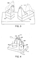
- First and second supports 200, 202 are mounted directly on a machine base 10 for rotation about the axes of rotation of the respective rotational machine axes which are perpendicular to the plane of the machine base.
- Points 204 and 206 denote reference points associated with each support.
- a reference axis 214 passes through reference point 204.
- a support arm 208 is carried out by the second support 202 and is moveable relative to the second support about a rotary axis 210.
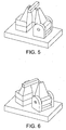
- Figures 4 to 6 show successive positions of machine tool components as the reference points 204 and 206 move over the surface of a notional workpiece represented by a cuboidal work zone 212. As the supports rotate in opposite directions, a constant spacing between the reference points is maintained in the direction of reference axis 214 by rotation of the support arm about axis 210.
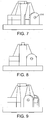
- FIG. 7 to 9 Side views of the machine tool orientations shown in Figures 4 to 6 are depicted in Figures 7 to 9 .
- a reference line 216 marked on a portion of support arm 208 extending through support 202 highlights changes in the rotational position of the support arm relative to the support.
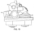
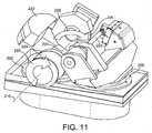
- a grinding machine is shown in Figures 10 and 11 .
- a grinding wheel 220 is provided with its rotational axis 222 in a horizontal orientation and spaced from horizontal rotary axis 210 by a support arm (not visible in these Figures).
- a workpiece 224 is mounted on the other support 202 (visible in Figure 11 ).
- Arrow 226 denotes movement of the axis of the grinding wheel along an arc as a result of its motion relative to rotary axis 210, with rotation about this axis being identified by arrow 228.
- the horizontal component of the motion of the grinding wheel about rotary axis 210 achieves the same horizontal correction motion as the linear machine axis present in machine tools described in WO2009/093064 .
- the third rotary axis drive motor 229 is mounted on the second support 202 with its centreline parallel to the wheelhead axis 222, and in particular with its centreline coincident with the third rotary axis 210.
- a counterweight 223 is also carried by the third rotary axis to assist with control of the wheelhead position relative to that axis.
- Figure 12 shows a CAD model that was used to demonstrate the control mathematics required to use the rotary motion about a horizontal rotary axis to provide corrective motion.
- Rotary axis angles calculated using the CAD model are shown in the following table: 50mm part 400mm wheel 401mm wheel Third rotary axis angle Range Third rotary axis angle Range -250mm 76.98826862 5.10805431 -250mm 77.06186038 5.11138475 0mm 71.88021431 0mm 71.95047563 250mm 76.98826862 250mm 77.06186038 51mm part 400mm wheel 401mm wheel Third rotary axis angle Range Third rotary axis angle Range Third rotary axis angle Range -250mm 77.06186038 -250mm 77.13546366 0mm 71.95047563 5.11138475 0mm 72.02074874 5.11471492 250mm 77.06186038 250mm 77.13546366
- the angular motion about the third rotary axis can be calculated in order to maintain the required motion profile between the cutting tool and the workpiece.
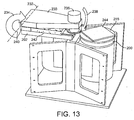
- FIG. 13 shows another machine tool configuration in accordance with an embodiment of the invention.
- a support arm 230 is pivotable about a third rotary axis 232 in the manner indicated by arrow 234.
- a grinding wheelhead 236 is mounted at the distal end of the support arm such that its rotational axis is orthogonal to the third rotary axis and to the radial direction relative to that axis extending along the support arm. Pivoting of the arm about the axis 232 results in motion of the grinding wheelhead in an arc, indicated by arrow 238.
- a flexure 240 is used to facilitate rotation of support arm 230 about the rotary axis 232 in the configuration shown in Figure 13 , but it will be appreciated that any kind of rotary coupling could be employed, such as a rotary bearing.
- the rotary driving force may be provided by a wide range of options, including an on-axis motor, an off-axis motor (via a belt or gear drive for example), or a cam drive.
- the support arm and flexure are mounted for movement along a linear axis 242 carried by the second support 202. This facilitates movement of the grinding wheelhead towards and away from a workpiece 244 mounted on the first support 200. This linear motion is also employed to correct for the horizontal component of the motion of the wheelhead about the third rotary axis 232.
- this movement about the third rotary axis may be used to raise and lower a grinding wheel orientated with its rotational axis substantially vertical (that is, orthogonal to the third rotary axis and the support arm). It may then be employed to form an edge profile on workpiece 244 (such as a silicon wafer), for example, or to move the wheel between a workpiece and a grinding wheel forming wheel 245 beneath it.
- workpiece 244 such as a silicon wafer
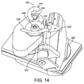
- FIG. 14 Another grinding machine is depicted in Figure 14 .
- a support arm 250 is rotatable about a third rotary axis 252.
- This axis has a vertical orientation, parallel with the axes of rotation of the first and second rotational machine axes. Movement of the support arm about this axis in the direction indicated by arrow 254 moves a grinding wheelhead 256 about the axis in an arc indicated by arrow 258. This serves to move a grinding wheel 260 mounted of the wheelhead horizontally towards and away from a workpiece 262 mounted on the first support 200.
- a tool in this case grinding wheel 260
- an arrangement of the form shown in Figure 14 employs a third rotary axis to provide motion close to that of a linear axis, whilst employing rotary axes only.
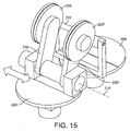
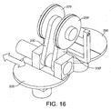
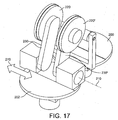
- Figures 15 to 18 show machine tools which include two tool mounts. Each tool mount is carried by a respective support arm 230, 230'.
- the tool mounts are arranged to carry respective grinding wheels to 220, 220', with movement thereof about the third rotary axis 210 providing a respective grinding infeed. This allows each grinding wheel to grind a different diameter simultaneously with the other.
- a separate rotary drive is provided for each support arm together with an associated position encoder.
- Each grinding wheel is therefore able to operate completely independently of the other. Two features may therefore be ground at the same time on a workpiece, which may be employed for example in orbital crankpin grinding.
- Support arm 230 is also mounted for linear movement along the rotary axis 210 to allow variation in the spacing in this direction between the two support arms.
- Figure 16 shows a similar view to that of Figure 15 , except that support arm 230 has been moved along and parallel to the rotary axis 210 to be closer to support arm 230'.
- the two support arms are supported by a common journal bearing shaft.
- the two support arms 230, 230' are mounted on separate support shafts.
- Support arm 230 is mounted for movement along a linear axis parallel to the rotary axis 210, facilitating movement in the direction indicated by arrow 270. This facilitates control of the separation between the two support arms and the associated tools mounted thereon.
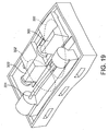
- FIG. 18 A further two mount configuration is shown in Figure 18 .
- a pair of support arms 230, 230' are mounted for rotation about a third rotary axis 210.
- respective linear drive arrangements 280, 280' are provided, acting in directions indicated by arrows 282, 282'.
- Each linear drive is coupled to a respective mount 284, 284' via respective pivots 286, 286'.
- the other end of each linear drive is coupled to the corresponding support arm.
- Pivot mount 284' is moveable along a linear axis parallel to rotary axis 210 providing movement in a direction indicated by arrow 288. This provides control of the spacing between the support arms 230, 230' and the associated tools.
- a known grinding machine tool configuration employing long linear axes to grind an elongate workpiece 224 is shown in Figure 19 .
- a grinding wheelhead 300 is shown in two different locations 300, 300'. This movement will be required to facilitate engagement of the grinding wheel with the full length of the workpiece.
- Each location 300, 300' has associated "thermal and stiffness loops", schematically indicated by ovals 302, 302' in Figure 19 .
- the stiffness loop is the shortest path through the machine's mechanical components and structure between the cutting tool and the component. The shorter the path, the stiffer the machine.
- the thermal loop is the shortest path through the machine's mechanical components and structure between the cutting tool and the component. The shorter the path the less susceptible to thermal distortions the machine will be.
- thermal loops 302, 302' are quite different. If grinding is started in position 300, this will lead to a temperature rise in this region of the machine relative to the remainder, so that as the wheelhead moves to position 300', a temperature gradient and associated alignment variations will be encountered.
- a typical "throat" motion during a thermal cycle of this machine could be 0.25mm.
- the throat is the section of the machine base that connects the grinding wheel mount to the component mount. It is the area that the grinding swarf and coolant collect in during the grinding process.
- the grinding swarf and coolant tend to heat the material of the throat underneath the grind zone.
- the region of the throat being heated changes, depending on the axial position along the components being ground. In the region of the throat being heated, the material expands, causing that region of the throat to open. Over time, the whole of the throat heats up, opening the throat. This can cause the grinding wheel position to move away from the component.
- the error motion will be largest where the throat is hottest. As there is no direct measurement of the position between the grinding wheel and the component, there is no feedback system to enable the errors caused by the opening throat to be compensated for.
- FIG. 20 A machine tool having two parallel rotational machine axes as described herein is shown in Figure 20 .
- An associated thermal/stiffness loop 310 is marked on the drawing.
- the thermal loop 310 is substantially unchanged, thereby avoiding inaccuracies resulting from a variable thermal loop.
- a central support 320 is provided between the rotational machine axes 322 and 324.
- each of the rotational machine axes is mounted onto a respective side of the support 320.
- Each machine axis is coupled to the adjacent side of the support by a mounting 326, 328, which extends horizontally between the respective axis and the support.
- the central support or slab thus carries the weight of each machine axis on either side.
- forces generated during operation of the machine tool act via the machine axes in opposite directions on the central support 320.
- the support resists these forces in a state of tension or compression, rather than in bending, as would be the case with a known machine bed. This results in a substantially constant (and potentially stiffer) stiffness loop in the machine tool irrespective of the orientations of the support 200, 202. This serves to reduce further errors during operation of the machine.
- Figures 21 to 23 shows successive positions of the machine tool when employed to grind a side of a rectangular tile 244 by way of example.
- grinding wheelhead 236 is moved along linear axis 242 only, with the rotational position of support 202 about the axis of rotation of the respective rotational machine axis 324 unchanged.
- Figures 27 to 32 are taken from WO2009/093064 . They illustrate capabilities of the machine tool described therein achievable using its configuration of two parallel rotational machine axes, with a linear axis mounted on one of the rotational axes. It will be appreciated that the component of motion provided by the linear axis in the illustrated configurations can be provided in accordance with machine tools described herein by means of a third rotary axis. Accordingly, a description of these Figures is included below.
- the linear machine axis is mounted upon a rotary axis. This enables the supports 100, 102 and mount 112 to be orientated such that the reference axes 108, 110 are parallel prior to movement of reference point 106 along the workpiece shoulder. This movement is then achieved by movement of mount 112 along its linear machine axis alone.
- Motion with respect to the three machine axes may be interpolated in order to enable access by reference point 106 to the length of the elongate workpiece 128.
- Figure 28 shows reference point 106 defining a spherical surface 140 equidistant from reference point 104 whilst maintaining its reference axis 110 in a perpendicular "tool normal" orientation with respect to that surface.
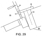
- Figure 29 illustrates how adjustment of the relative rotational orientations of the tool support 22 and workpiece support 20 can be used to create an angle between the rotational axis 50 of a grinding wheel 36 and the longitudinal axis 52 of a workpiece 24, to facilitate formation of a tapered profile on the workpiece.
- This principle can also be used to generate other profiles or forms, such as crown profiles on roller bearings.
- Figure 30 illustrates how a pre-formed grinding wheel 60 may be employed using a machine tool embodying the invention to form predetermined profiles on a workpiece 24.
- the machine base may be formed from granite, cast iron or polymer concrete for example and its fabrication may be relatively inexpensive in comparison to a base for an existing machine tool employing long linear axes.
- the precision of the interpolated linear motion between a cutting tool and a workpiece may be measured and any compensation required calculated.
- This compensation may be incorporated into the instructions governing operation of the controller of the machine tool, for example in software.
- Laser calibration may be employed with regard to angle, linear position and straightness, enabling error correction of movement with respect to the rotary and linear axes.
- Figures 31 and 32 show how the machine can be laser calibrated.
- a light source 70 is mounted on headstock 26 which generates two parallel laser beams 72, 74 which are incident on a detector 76 carried by the tool support 22.
- the calibration procedure could include the following steps:
- each rotational axis is monitored using respective rotation sensors separate from those used during normal operation of the machine tool.
- these dedicated calibration sensors facilitate calibration independently of the normal sensors.
- the calibration process may then measure and enable correction of machine motion errors caused by the operation control sensors.
- a linear encoder may be employed (such as a laser interferometer mounted between the two rotary axes) as a secondary encoder to minimise the linear position errors caused by rotary encoder errors.
- Machine tools described herein may use rotary encoders to synchronize motion between two rotary axes. It may be possible to maintain around 1 arc second absolute position error between the two axes.
- a rotary position error produces a linear error at a given radius of approximately 5 micron (of linear error) per metre (of radius) per arc second (of error).
- the radius from rotary axis centre to the end of the component may be around 900mm, for example. This results in a linear position error (in the axial direction of the component) of around 3micron per arc second of error.
- RLE10 an example of a long range linear laser encoder
- RTM Renishaw
- An encoder of this type could be used to provide linear position feedback as the two rotary axes move relative to each other.
- axial position errors resulting between the cutting tool and the component from rotary encoder errors can be measured directly as linear position errors.
- the configuration of the linear encoder would be similar to that shown above in Figures 31 and 32 for the machine calibration procedure. However, the encoder's laser and target would need to be enclosed in a cover (not shown in the Figures), away from (probably below) the machining contact position.
- the output signals from sensors employed during the calibration procedure are fed to the machine's control arrangement or to a dedicated calibration processing arrangement.
- the sensor signals are processed to identify any corrections that need to be applied to the control configuration of the machine tool to minimise any detected positioning errors.
- references herein to orthogonal or parallel relative orientations and the like are to be interpreted as defining substantially orthogonal or parallel relationships between components within practical tolerances.
Landscapes
- Engineering & Computer Science (AREA)
- Mechanical Engineering (AREA)
- Grinding Of Cylindrical And Plane Surfaces (AREA)
- Machine Tool Units (AREA)
- Finish Polishing, Edge Sharpening, And Grinding By Specific Grinding Devices (AREA)
- Automatic Control Of Machine Tools (AREA)
Claims (15)
- Werkzeugmaschine, die Folgendes umfasst:eine Maschinenbasis;einen ersten Träger (200), der auf einer ersten Maschinendrehachse (322) vorgesehen ist, wobei die erste Drehachse auf der Basis in einer festen Position relativ zu der Basis befestigt ist;einen zweiten Träger (202), der auf einer zweiten Maschinendrehachse (324) bereitgestellt ist, wobei die zweite Drehachse auf der Basis in einer festen Position relativ zu der Basis befestigt ist, wobei die Rotationsachse der zweiten Drehachse zu der Rotationsachse der ersten Drehachse parallel ist und von dieser seitlich beabstandet angeordnet ist;eine Halterung, die von dem zweiten Träger getragen wird und relativ zum zweiten Träger beweglich ist; undeine Steueranordnung, die betreibbar ist, um die Ausrichtung des ersten Trägers (200) relativ zu der Rotationsachse der ersten Drehachse (322) und um die Ausrichtung der Halterung relativ zu der Rotationsachse der zweiten Drehachse (324) zu steuern, um die Position und die Ausrichtung des ersten Trägers und der Halterung relativ zueinander zu steuern,dadurch gekennzeichnet, dass
die Maschinenbasis einen mittleren Träger (320) umfasst, der zwischen den Maschinenachsen (322, 324) positioniert ist, und die Maschinenachsen auf einander gegenüberliegenden Seiten des Trägers angebracht sind. - Werkzeugmaschine nach Anspruch 1, wobei das Gewicht beider der Maschinenachsen (322, 324) von dem mittleren Träger (320) im Wesentlichen gestützt wird.
- Werkzeugmaschine nach Anspruch 1 oder Anspruch 2, wobei die Halterung von einem Trägerarm (208, 230, 250) am zweiten Träger (202) getragen wird, wobei der Trägerarm relativ zu dem zweiten Träger um eine Drehachse (210, 232, 252) beweglich ist und die Steueranordnung betreibbar ist, um die Drehposition der Halterung um die Drehachse zu steuern.
- Werkzeugmaschine nach einem vorhergehenden Anspruch, wobei:die Halterung von einem Trägerarm (208, 230, 250) am zweiten Träger (202) getragen wird, wobei der Trägerarm relativ zu dem zweiten Träger um eine Drehachse (210, 232, 252) beweglich ist; unddie Steueranordnung außerdem betreibbar ist, um die Drehposition der Halterung um die Drehachse zu steuern, um die Position und die Ausrichtung des ersten Trägers (200) und der Halterung relativ zueinander zu steuern.
- Werkzeugmaschine nach Anspruch 4, wobei die Drehachse (210, 232) zu der Rotationsachse der zweiten Maschinendrehachse (324) orthogonal ist.
- Werkzeugmaschine nach Anspruch 4, wobei die Drehachse zu der Rotationsachse der zweiten Maschinendrehachse (324) parallel ist.
- Werkzeugmaschine nach einem vorhergehenden Anspruch, wobei die Träger (200, 202) um ihre jeweilige Maschinendrehachse (322, 324) unabhängig drehbar sind.
- Werkzeugmaschine nach einem der Ansprüche 1 bis 6, wobei die Träger (200, 202) zur Drehung um ihre jeweilige Maschinendrehachse (322, 324) angeordnet sind, so dass einer Drehbewegung eines Trägers in eine Richtung durch eine Drehung des anderen Trägers, aber in die entgegengesetzte Richtung, im Wesentlichen entsprochen wird.
- Werkzeugmaschine nach einem vorhergehenden Anspruch, wobei die Drehpositionen der Träger (200, 202) relativ zu der Maschinenbasis selektiv verriegelbar sind.
- Werkzeugmaschine nach einem vorhergehenden Anspruch, wobei die Träger (200, 202) durch Zapfen- und Drucklager auf der Maschinenbasis gestützt werden.
- Werkzeugmaschine nach einem vorhergehenden Anspruch, wobei die Träger (200, 202) durch einen jeweiligen Direktantriebsmotor relativ zur Maschine drehbar sind.
- Werkzeugmaschine nach einem vorhergehenden Anspruch, wobei jeder Träger (200, 202) einen Drehsensor enthält, um ein Signal, das auf die Drehpositionen des jeweiligen Trägers relativ zu der Maschinenbasis bezogen ist, bereitzustellen, und wobei die Steueranordnung betreibbar ist, um die Signale von den Drehsensoren zu empfangen und um während eines Maschinenbetriebs eine Ungenauigkeit in der Bewegung der Träger zu kompensieren.
- Werkzeugmaschine nach einem vorhergehenden Anspruch, wobei die Bewegung des Trägerarms (208, 230, 250) relativ zu dem zweiten Träger (202) um die Drehachse (210, 232, 252) durch ein Drehlager bereitgestellt wird.
- Werkzeugmaschine nach einem der Ansprüche 1 bis 12, wobei die Bewegung des Trägerarms (230) relativ zu dem zweiten Träger (202) um die Drehachse (232) durch eine Biegung (240) bereitgestellt wird.
- Werkzeugmaschine nach Anspruch 14, wobei die Biegung (240) relativ zu der Basis entlang einer geradlinigen zu der Basis parallelen Achse (242) beweglich ist.
Applications Claiming Priority (2)
| Application Number | Priority Date | Filing Date | Title |
|---|---|---|---|
| GB0922392.6A GB2476468B (en) | 2009-12-22 | 2009-12-22 | Machine tools and methods of operation thereof |
| EP10812986.7A EP2516108B1 (de) | 2009-12-22 | 2010-12-20 | Maschinenwerkzeuge und betriebsverfahren dafür |
Related Parent Applications (1)
| Application Number | Title | Priority Date | Filing Date |
|---|---|---|---|
| EP10812986.7A Division EP2516108B1 (de) | 2009-12-22 | 2010-12-20 | Maschinenwerkzeuge und betriebsverfahren dafür |
Publications (3)
| Publication Number | Publication Date |
|---|---|
| EP2684640A2 EP2684640A2 (de) | 2014-01-15 |
| EP2684640A3 EP2684640A3 (de) | 2014-08-20 |
| EP2684640B1 true EP2684640B1 (de) | 2016-10-19 |
Family
ID=41717375
Family Applications (2)
| Application Number | Title | Priority Date | Filing Date |
|---|---|---|---|
| EP13184618.0A Active EP2684640B1 (de) | 2009-12-22 | 2010-12-20 | Werkzeugemaschine und verfahren unter verwendung einer solchen maschine |
| EP10812986.7A Active EP2516108B1 (de) | 2009-12-22 | 2010-12-20 | Maschinenwerkzeuge und betriebsverfahren dafür |
Family Applications After (1)
| Application Number | Title | Priority Date | Filing Date |
|---|---|---|---|
| EP10812986.7A Active EP2516108B1 (de) | 2009-12-22 | 2010-12-20 | Maschinenwerkzeuge und betriebsverfahren dafür |
Country Status (6)
| Country | Link |
|---|---|
| US (1) | US9248535B2 (de) |
| EP (2) | EP2684640B1 (de) |
| CN (1) | CN102639289B (de) |
| ES (2) | ES2443161T3 (de) |
| GB (1) | GB2476468B (de) |
| WO (1) | WO2011077127A2 (de) |
Families Citing this family (18)
| Publication number | Priority date | Publication date | Assignee | Title |
|---|---|---|---|---|
| DE102010049267B4 (de) | 2010-10-25 | 2016-03-31 | Schneider Gmbh & Co. Kg | Werkstückspindel mit Festkörpergelenk |
| DE102011000335B4 (de) * | 2011-01-26 | 2016-04-07 | Walter Maschinenbau Gmbh | Maschine zur Bearbeitung und/oder Messung eines Werkstücks mit zwei schwenkbaren Traversen |
| AU2013392911B2 (en) * | 2013-06-18 | 2016-12-01 | Colgate-Palmolive Company | Antimicrobial compositions comprising essential oil combinations |
| CN104227440B (zh) * | 2013-06-23 | 2016-12-28 | 芜湖杰诺瑞汽车电器系统有限公司 | 可调节定位的铣夹具 |
| CN104834271B (zh) * | 2015-06-03 | 2017-08-25 | 上海理工大学 | 基于动刚度评价的直接进给轴伺服参数优化方法 |
| CN105290804B (zh) * | 2015-11-06 | 2017-08-08 | 宁波大红鹰学院 | 气动与液压控制的自动钻削工作台装置及其工作方法 |
| TWI614513B (zh) * | 2016-12-22 | 2018-02-11 | 量測移動平台之多自由度誤差之方法及裝置 | |
| GB201701246D0 (en) * | 2017-01-25 | 2017-03-08 | Fives Landis Ltd | Machine tools and methods of operation thereof |
| DE102017121526A1 (de) * | 2017-09-15 | 2019-03-21 | Rollomatic S.A. | Vorrichtung zur Ausrichtung und Positionierung eines Werkstücks relativ zu einem Laserstrahl einer Laserbearbeitungsmaschine |
| CN108453622A (zh) * | 2018-03-27 | 2018-08-28 | 成都与俱科技有限公司 | 转动机构及其在机加工中的应用 |
| US11241767B2 (en) | 2018-06-01 | 2022-02-08 | Fives Landis Corp. | Pendulum grinding machine |
| CN109457985B (zh) * | 2018-12-18 | 2023-10-31 | 江苏杜邦建设工程有限公司 | 钢网架球节点安装标高调节装置 |
| CN110834242B (zh) * | 2019-11-27 | 2025-04-29 | 科德数控股份有限公司 | 一种龙门磨床 |
| GB2589874B (en) | 2019-12-10 | 2024-05-01 | Fives Landis Ltd | Machine tools and methods of operation thereof |
| JP7730534B2 (ja) * | 2021-06-14 | 2025-08-28 | テクノダイナミックス株式会社 | 傾斜回転テーブル装置 |
| GB2621878A (en) * | 2022-08-26 | 2024-02-28 | Fives Landis Ltd | Thermal distortion in machine tools |
| GB2624404A (en) * | 2022-11-16 | 2024-05-22 | Fives Landis Ltd | Machine tools for machining a workpiece and methods of operation thereof |
| GB2626305A (en) * | 2023-01-10 | 2024-07-24 | Fives Landis Ltd | A machine tool and a rotary machine drive for a machine tool |
Family Cites Families (28)
| Publication number | Priority date | Publication date | Assignee | Title |
|---|---|---|---|---|
| GB1302869A (de) * | 1969-11-25 | 1973-01-10 | ||
| GB1424353A (en) | 1972-03-03 | 1976-02-11 | Cranfield Inst Of Tech | Machines for machining slots in workpieces |
| US4068413A (en) * | 1975-10-02 | 1978-01-17 | Suddarth Jack M | Adjustable lens grinding apparatus |
| US4115956A (en) * | 1977-06-28 | 1978-09-26 | S. E. Huffman Corporation | Programmably controlled machine for grinding end cutting tools and the like |
| US4186529A (en) * | 1977-06-28 | 1980-02-05 | S. E. Huffman Corporation | Programmably controlled method for grinding end cutting tools and the like |
| DE3133488C2 (de) * | 1981-08-25 | 1994-07-28 | Montanwerke Walter GmbH, 7400 Tübingen | Programmgesteuerte Werkzeugschleifmaschine |
| US4608643A (en) * | 1983-08-18 | 1986-08-26 | Spiral Step Tool Company | Automatic tool grinding machine with computerized control |
| GB8325027D0 (en) * | 1983-09-19 | 1983-10-19 | Robertson Eng Thame Ltd | Aspheric cutting lathe |
| US4760672A (en) * | 1986-12-10 | 1988-08-02 | Corning Glass Works | Simultaneously grinding and polishing preforms for optical lenses |
| DE8711828U1 (de) * | 1987-09-01 | 1988-01-28 | Gühring Automation GmbH & Co, 72510 Stetten | Werkzeugmaschine zur Bearbeitung von Werkstücken mittels rundlaufender Werkzeuge |
| US5231587A (en) * | 1990-07-12 | 1993-07-27 | Loh Optical Machinery, Inc. | Computer controlled lens surfacer |
| EP0816012A1 (de) * | 1996-06-26 | 1998-01-07 | Starrfräsmaschinen AG | Starr-Bearbeitungszentrum |
| JP3685879B2 (ja) * | 1996-07-26 | 2005-08-24 | 東芝機械株式会社 | 旋回可能な主軸頭を有する工作機械 |
| DE19902137C1 (de) * | 1999-01-20 | 2000-06-29 | Ilg Gmbh | Werkzeugmaschine zum Schleifen von Werkstücken |
| SE9901484D0 (sv) * | 1999-04-26 | 1999-04-26 | Lidkoeping Machine Tools Ab | Abrasive machine |
| GB0002251D0 (en) * | 2000-02-02 | 2000-03-22 | Unova Uk Ltd | Improvements in and relating to grinding machines |
| US6553875B1 (en) | 2000-08-07 | 2003-04-29 | Toshiharu (Tom) Miyano | Machine tool assembly |
| US7275468B2 (en) | 2002-05-29 | 2007-10-02 | Massachusetts Institute Of Technology | Rotary fast tool servo system and methods |
| ITTO20030502A1 (it) * | 2003-07-01 | 2005-01-02 | O M V Ohg Venete S R L | Macchina a controllo numerico. |
| GB2408224B (en) | 2003-11-21 | 2005-11-09 | Unova Uk Ltd | Improvements in and relating to grinding machines |
| ES2385652T3 (es) * | 2005-02-14 | 2012-07-27 | Klingelnberg Gmbh | Dispositivo y procedimiento de mecanización blanda de ruedas dentadas cónicas |
| JP4938782B2 (ja) * | 2005-10-18 | 2012-05-23 | ジーエスアイ・グループ・コーポレーション | 光学的基準を利用する方法および装置 |
| US20080047120A1 (en) | 2006-08-24 | 2008-02-28 | Hardinge, Inc. | Rotary table with frameless motor |
| GB0617270D0 (en) | 2006-09-02 | 2006-10-11 | Cinetic Landis Grinding Ltd | Grinding machines and methods of operation thereof |
| US7874895B1 (en) * | 2006-11-23 | 2011-01-25 | Jeffrey Toycen | Benchtop end mill grinding center |
| CN100544870C (zh) * | 2007-04-25 | 2009-09-30 | 杨林 | 大型曲线齿锥齿轮加工数控机床 |
| DE102007031703A1 (de) * | 2007-07-06 | 2009-01-08 | Satisloh Gmbh | Maschine zur Bearbeitung von optischen Werkstücken, insbesondere von Kunststoff-Brillengläsern |
| GB0801366D0 (en) * | 2008-01-25 | 2008-03-05 | Cinetic Landis Grinding Ltd | Machine tools and methods of operation thereof |
-
2009
- 2009-12-22 GB GB0922392.6A patent/GB2476468B/en active Active
-
2010
- 2010-12-20 WO PCT/GB2010/052155 patent/WO2011077127A2/en not_active Ceased
- 2010-12-20 ES ES10812986.7T patent/ES2443161T3/es active Active
- 2010-12-20 CN CN201080052876.0A patent/CN102639289B/zh active Active
- 2010-12-20 ES ES13184618.0T patent/ES2606860T3/es active Active
- 2010-12-20 EP EP13184618.0A patent/EP2684640B1/de active Active
- 2010-12-20 US US13/511,161 patent/US9248535B2/en active Active
- 2010-12-20 EP EP10812986.7A patent/EP2516108B1/de active Active
Also Published As
| Publication number | Publication date |
|---|---|
| EP2684640A3 (de) | 2014-08-20 |
| GB2476468A (en) | 2011-06-29 |
| US20120276813A1 (en) | 2012-11-01 |
| EP2684640A2 (de) | 2014-01-15 |
| GB2476468B (en) | 2012-08-15 |
| WO2011077127A4 (en) | 2012-03-15 |
| ES2606860T3 (es) | 2017-03-28 |
| ES2443161T3 (es) | 2014-02-18 |
| WO2011077127A2 (en) | 2011-06-30 |
| EP2516108A2 (de) | 2012-10-31 |
| CN102639289B (zh) | 2015-12-02 |
| US9248535B2 (en) | 2016-02-02 |
| GB0922392D0 (en) | 2010-02-03 |
| WO2011077127A3 (en) | 2012-01-12 |
| CN102639289A (zh) | 2012-08-15 |
| EP2516108B1 (de) | 2013-11-27 |
Similar Documents
| Publication | Publication Date | Title |
|---|---|---|
| EP2684640B1 (de) | Werkzeugemaschine und verfahren unter verwendung einer solchen maschine | |
| US9630294B2 (en) | Machine tools and methods of operation thereof | |
| CN100400225C (zh) | 非球面光学零件复合加工、检测机床 | |
| KR100835951B1 (ko) | 베벨 기어를 만드는 기계 및 방법 | |
| US10092956B2 (en) | Device and method for machining an optical workpiece | |
| JP5384196B2 (ja) | 超精密ロール旋盤 | |
| JP4875184B2 (ja) | 工具回転半径可変の工具ホルダおよび該工具を備えた工作機械ならびに前記工作機械を用いた加工方法 | |
| Leadbeater et al. | A unique machine for grinding large, off-axis optical components: the OAGM 2500 | |
| JP7685442B2 (ja) | 溝状の外形を有する回転部品をロール機械加工する工作機械及び方法 | |
| CA2221156A1 (en) | Improvements in and relating to machine tools | |
| CN115351359A (zh) | 一种磨削螺旋锥齿轮的磨齿机床 | |
| GB2491020A (en) | Machine tool with central support between machine axes | |
| JP3337445B2 (ja) | 工作機械 | |
| US20050118928A1 (en) | Machine tool with 5 machining axes with a continuous grinding tool profilling system | |
| JP5401858B2 (ja) | 研削盤および研削方法 | |
| McKeown et al. | The design and development of a large ultra-precision CNC diamond turning machine | |
| Carlisle et al. | Experiences in the development of ultra stiff CNC aspheric generating machine tools for ductile regime grinding of brittle materials | |
| JPH08276338A (ja) | 回転体の姿勢調整機構 | |
| JPS63232965A (ja) | 加工体研削方法 | |
| JPH01240259A (ja) | 数値制御加工機 | |
| JP2005305589A (ja) | 加工方法及び工作機械 | |
| HK1093708B (en) | Machine for machining optical workpieces | |
| HK1093708A1 (zh) | 用於机加工光学工件的机床 | |
| JPH05293685A (ja) | レーザー加工機旋回軸のアライメント装置 |
Legal Events
| Date | Code | Title | Description |
|---|---|---|---|
| PUAI | Public reference made under article 153(3) epc to a published international application that has entered the european phase |
Free format text: ORIGINAL CODE: 0009012 |
|
| AC | Divisional application: reference to earlier application |
Ref document number: 2516108 Country of ref document: EP Kind code of ref document: P |
|
| AK | Designated contracting states |
Kind code of ref document: A2 Designated state(s): AL AT BE BG CH CY CZ DE DK EE ES FI FR GB GR HR HU IE IS IT LI LT LU LV MC MK MT NL NO PL PT RO RS SE SI SK SM TR |
|
| PUAL | Search report despatched |
Free format text: ORIGINAL CODE: 0009013 |
|
| AK | Designated contracting states |
Kind code of ref document: A3 Designated state(s): AL AT BE BG CH CY CZ DE DK EE ES FI FR GB GR HR HU IE IS IT LI LT LU LV MC MK MT NL NO PL PT RO RS SE SI SK SM TR |
|
| RIC1 | Information provided on ipc code assigned before grant |
Ipc: B24B 19/00 20060101ALI20140715BHEP Ipc: B23B 5/08 20060101ALI20140715BHEP Ipc: B23Q 1/36 20060101AFI20140715BHEP Ipc: B24B 27/00 20060101ALI20140715BHEP Ipc: B24B 5/04 20060101ALI20140715BHEP Ipc: B24B 27/04 20060101ALI20140715BHEP Ipc: B23Q 1/01 20060101ALI20140715BHEP Ipc: B23Q 1/54 20060101ALI20140715BHEP |
|
| 17P | Request for examination filed |
Effective date: 20140916 |
|
| RBV | Designated contracting states (corrected) |
Designated state(s): AL AT BE BG CH CY CZ DE DK EE ES FI FR GB GR HR HU IE IS IT LI LT LU LV MC MK MT NL NO PL PT RO RS SE SI SK SM TR |
|
| RAP1 | Party data changed (applicant data changed or rights of an application transferred) |
Owner name: FIVES LANDIS LIMITED |
|
| GRAP | Despatch of communication of intention to grant a patent |
Free format text: ORIGINAL CODE: EPIDOSNIGR1 |
|
| INTG | Intention to grant announced |
Effective date: 20160520 |
|
| GRAS | Grant fee paid |
Free format text: ORIGINAL CODE: EPIDOSNIGR3 |
|
| GRAA | (expected) grant |
Free format text: ORIGINAL CODE: 0009210 |
|
| AC | Divisional application: reference to earlier application |
Ref document number: 2516108 Country of ref document: EP Kind code of ref document: P |
|
| AK | Designated contracting states |
Kind code of ref document: B1 Designated state(s): AL AT BE BG CH CY CZ DE DK EE ES FI FR GB GR HR HU IE IS IT LI LT LU LV MC MK MT NL NO PL PT RO RS SE SI SK SM TR |
|
| REG | Reference to a national code |
Ref country code: GB Ref legal event code: FG4D |
|
| REG | Reference to a national code |
Ref country code: CH Ref legal event code: EP |
|
| REG | Reference to a national code |
Ref country code: AT Ref legal event code: REF Ref document number: 837913 Country of ref document: AT Kind code of ref document: T Effective date: 20161115 |
|
| REG | Reference to a national code |
Ref country code: IE Ref legal event code: FG4D |
|
| REG | Reference to a national code |
Ref country code: DE Ref legal event code: R096 Ref document number: 602010037408 Country of ref document: DE |
|
| REG | Reference to a national code |
Ref country code: FR Ref legal event code: PLFP Year of fee payment: 7 |
|
| REG | Reference to a national code |
Ref country code: NL Ref legal event code: MP Effective date: 20161019 |
|
| REG | Reference to a national code |
Ref country code: LT Ref legal event code: MG4D |
|
| PG25 | Lapsed in a contracting state [announced via postgrant information from national office to epo] |
Ref country code: LV Free format text: LAPSE BECAUSE OF FAILURE TO SUBMIT A TRANSLATION OF THE DESCRIPTION OR TO PAY THE FEE WITHIN THE PRESCRIBED TIME-LIMIT Effective date: 20161019 |
|
| REG | Reference to a national code |
Ref country code: AT Ref legal event code: MK05 Ref document number: 837913 Country of ref document: AT Kind code of ref document: T Effective date: 20161019 |
|
| PG25 | Lapsed in a contracting state [announced via postgrant information from national office to epo] |
Ref country code: GR Free format text: LAPSE BECAUSE OF FAILURE TO SUBMIT A TRANSLATION OF THE DESCRIPTION OR TO PAY THE FEE WITHIN THE PRESCRIBED TIME-LIMIT Effective date: 20170120 Ref country code: NO Free format text: LAPSE BECAUSE OF FAILURE TO SUBMIT A TRANSLATION OF THE DESCRIPTION OR TO PAY THE FEE WITHIN THE PRESCRIBED TIME-LIMIT Effective date: 20170119 Ref country code: LT Free format text: LAPSE BECAUSE OF FAILURE TO SUBMIT A TRANSLATION OF THE DESCRIPTION OR TO PAY THE FEE WITHIN THE PRESCRIBED TIME-LIMIT Effective date: 20161019 Ref country code: SE Free format text: LAPSE BECAUSE OF FAILURE TO SUBMIT A TRANSLATION OF THE DESCRIPTION OR TO PAY THE FEE WITHIN THE PRESCRIBED TIME-LIMIT Effective date: 20161019 |
|
| PG25 | Lapsed in a contracting state [announced via postgrant information from national office to epo] |
Ref country code: HR Free format text: LAPSE BECAUSE OF FAILURE TO SUBMIT A TRANSLATION OF THE DESCRIPTION OR TO PAY THE FEE WITHIN THE PRESCRIBED TIME-LIMIT Effective date: 20161019 Ref country code: PT Free format text: LAPSE BECAUSE OF FAILURE TO SUBMIT A TRANSLATION OF THE DESCRIPTION OR TO PAY THE FEE WITHIN THE PRESCRIBED TIME-LIMIT Effective date: 20170220 Ref country code: NL Free format text: LAPSE BECAUSE OF FAILURE TO SUBMIT A TRANSLATION OF THE DESCRIPTION OR TO PAY THE FEE WITHIN THE PRESCRIBED TIME-LIMIT Effective date: 20161019 Ref country code: RS Free format text: LAPSE BECAUSE OF FAILURE TO SUBMIT A TRANSLATION OF THE DESCRIPTION OR TO PAY THE FEE WITHIN THE PRESCRIBED TIME-LIMIT Effective date: 20161019 Ref country code: AT Free format text: LAPSE BECAUSE OF FAILURE TO SUBMIT A TRANSLATION OF THE DESCRIPTION OR TO PAY THE FEE WITHIN THE PRESCRIBED TIME-LIMIT Effective date: 20161019 Ref country code: IS Free format text: LAPSE BECAUSE OF FAILURE TO SUBMIT A TRANSLATION OF THE DESCRIPTION OR TO PAY THE FEE WITHIN THE PRESCRIBED TIME-LIMIT Effective date: 20170219 Ref country code: FI Free format text: LAPSE BECAUSE OF FAILURE TO SUBMIT A TRANSLATION OF THE DESCRIPTION OR TO PAY THE FEE WITHIN THE PRESCRIBED TIME-LIMIT Effective date: 20161019 Ref country code: BE Free format text: LAPSE BECAUSE OF FAILURE TO SUBMIT A TRANSLATION OF THE DESCRIPTION OR TO PAY THE FEE WITHIN THE PRESCRIBED TIME-LIMIT Effective date: 20161019 Ref country code: PL Free format text: LAPSE BECAUSE OF FAILURE TO SUBMIT A TRANSLATION OF THE DESCRIPTION OR TO PAY THE FEE WITHIN THE PRESCRIBED TIME-LIMIT Effective date: 20161019 |
|
| REG | Reference to a national code |
Ref country code: DE Ref legal event code: R097 Ref document number: 602010037408 Country of ref document: DE |
|
| PG25 | Lapsed in a contracting state [announced via postgrant information from national office to epo] |
Ref country code: EE Free format text: LAPSE BECAUSE OF FAILURE TO SUBMIT A TRANSLATION OF THE DESCRIPTION OR TO PAY THE FEE WITHIN THE PRESCRIBED TIME-LIMIT Effective date: 20161019 Ref country code: SK Free format text: LAPSE BECAUSE OF FAILURE TO SUBMIT A TRANSLATION OF THE DESCRIPTION OR TO PAY THE FEE WITHIN THE PRESCRIBED TIME-LIMIT Effective date: 20161019 Ref country code: CZ Free format text: LAPSE BECAUSE OF FAILURE TO SUBMIT A TRANSLATION OF THE DESCRIPTION OR TO PAY THE FEE WITHIN THE PRESCRIBED TIME-LIMIT Effective date: 20161019 Ref country code: RO Free format text: LAPSE BECAUSE OF FAILURE TO SUBMIT A TRANSLATION OF THE DESCRIPTION OR TO PAY THE FEE WITHIN THE PRESCRIBED TIME-LIMIT Effective date: 20161019 Ref country code: DK Free format text: LAPSE BECAUSE OF FAILURE TO SUBMIT A TRANSLATION OF THE DESCRIPTION OR TO PAY THE FEE WITHIN THE PRESCRIBED TIME-LIMIT Effective date: 20161019 |
|
| PLBE | No opposition filed within time limit |
Free format text: ORIGINAL CODE: 0009261 |
|
| STAA | Information on the status of an ep patent application or granted ep patent |
Free format text: STATUS: NO OPPOSITION FILED WITHIN TIME LIMIT |
|
| PG25 | Lapsed in a contracting state [announced via postgrant information from national office to epo] |
Ref country code: BG Free format text: LAPSE BECAUSE OF FAILURE TO SUBMIT A TRANSLATION OF THE DESCRIPTION OR TO PAY THE FEE WITHIN THE PRESCRIBED TIME-LIMIT Effective date: 20170119 Ref country code: SM Free format text: LAPSE BECAUSE OF FAILURE TO SUBMIT A TRANSLATION OF THE DESCRIPTION OR TO PAY THE FEE WITHIN THE PRESCRIBED TIME-LIMIT Effective date: 20161019 |
|
| 26N | No opposition filed |
Effective date: 20170720 |
|
| PG25 | Lapsed in a contracting state [announced via postgrant information from national office to epo] |
Ref country code: MC Free format text: LAPSE BECAUSE OF FAILURE TO SUBMIT A TRANSLATION OF THE DESCRIPTION OR TO PAY THE FEE WITHIN THE PRESCRIBED TIME-LIMIT Effective date: 20161019 |
|
| REG | Reference to a national code |
Ref country code: IE Ref legal event code: MM4A |
|
| PG25 | Lapsed in a contracting state [announced via postgrant information from national office to epo] |
Ref country code: LU Free format text: LAPSE BECAUSE OF NON-PAYMENT OF DUE FEES Effective date: 20161220 |
|
| PG25 | Lapsed in a contracting state [announced via postgrant information from national office to epo] |
Ref country code: IE Free format text: LAPSE BECAUSE OF NON-PAYMENT OF DUE FEES Effective date: 20161220 Ref country code: SI Free format text: LAPSE BECAUSE OF FAILURE TO SUBMIT A TRANSLATION OF THE DESCRIPTION OR TO PAY THE FEE WITHIN THE PRESCRIBED TIME-LIMIT Effective date: 20161019 |
|
| REG | Reference to a national code |
Ref country code: FR Ref legal event code: PLFP Year of fee payment: 8 |
|
| PG25 | Lapsed in a contracting state [announced via postgrant information from national office to epo] |
Ref country code: CY Free format text: LAPSE BECAUSE OF FAILURE TO SUBMIT A TRANSLATION OF THE DESCRIPTION OR TO PAY THE FEE WITHIN THE PRESCRIBED TIME-LIMIT Effective date: 20161019 Ref country code: HU Free format text: LAPSE BECAUSE OF FAILURE TO SUBMIT A TRANSLATION OF THE DESCRIPTION OR TO PAY THE FEE WITHIN THE PRESCRIBED TIME-LIMIT; INVALID AB INITIO Effective date: 20101220 |
|
| PG25 | Lapsed in a contracting state [announced via postgrant information from national office to epo] |
Ref country code: MK Free format text: LAPSE BECAUSE OF FAILURE TO SUBMIT A TRANSLATION OF THE DESCRIPTION OR TO PAY THE FEE WITHIN THE PRESCRIBED TIME-LIMIT Effective date: 20161019 |
|
| PG25 | Lapsed in a contracting state [announced via postgrant information from national office to epo] |
Ref country code: MT Free format text: LAPSE BECAUSE OF NON-PAYMENT OF DUE FEES Effective date: 20161220 |
|
| PG25 | Lapsed in a contracting state [announced via postgrant information from national office to epo] |
Ref country code: TR Free format text: LAPSE BECAUSE OF FAILURE TO SUBMIT A TRANSLATION OF THE DESCRIPTION OR TO PAY THE FEE WITHIN THE PRESCRIBED TIME-LIMIT Effective date: 20161019 |
|
| PG25 | Lapsed in a contracting state [announced via postgrant information from national office to epo] |
Ref country code: AL Free format text: LAPSE BECAUSE OF FAILURE TO SUBMIT A TRANSLATION OF THE DESCRIPTION OR TO PAY THE FEE WITHIN THE PRESCRIBED TIME-LIMIT Effective date: 20161019 |
|
| PGFP | Annual fee paid to national office [announced via postgrant information from national office to epo] |
Ref country code: ES Payment date: 20250102 Year of fee payment: 15 |
|
| PGFP | Annual fee paid to national office [announced via postgrant information from national office to epo] |
Ref country code: CH Payment date: 20250101 Year of fee payment: 15 |
|
| REG | Reference to a national code |
Ref country code: CH Ref legal event code: U11 Free format text: ST27 STATUS EVENT CODE: U-0-0-U10-U11 (AS PROVIDED BY THE NATIONAL OFFICE) Effective date: 20260101 |
|
| PGFP | Annual fee paid to national office [announced via postgrant information from national office to epo] |
Ref country code: DE Payment date: 20251126 Year of fee payment: 16 |
|
| PGFP | Annual fee paid to national office [announced via postgrant information from national office to epo] |
Ref country code: GB Payment date: 20251119 Year of fee payment: 16 |
|
| PGFP | Annual fee paid to national office [announced via postgrant information from national office to epo] |
Ref country code: IT Payment date: 20251119 Year of fee payment: 16 |
|
| PGFP | Annual fee paid to national office [announced via postgrant information from national office to epo] |
Ref country code: FR Payment date: 20251120 Year of fee payment: 16 |