EP2683096B1 - Base station apparatus, user apparatus and communication control method - Google Patents
Base station apparatus, user apparatus and communication control method Download PDFInfo
- Publication number
- EP2683096B1 EP2683096B1 EP13186821.8A EP13186821A EP2683096B1 EP 2683096 B1 EP2683096 B1 EP 2683096B1 EP 13186821 A EP13186821 A EP 13186821A EP 2683096 B1 EP2683096 B1 EP 2683096B1
- Authority
- EP
- European Patent Office
- Prior art keywords
- transmit
- reference signal
- base station
- sounding reference
- antennas
- Prior art date
- Legal status (The legal status is an assumption and is not a legal conclusion. Google has not performed a legal analysis and makes no representation as to the accuracy of the status listed.)
- Active
Links
Images


Classifications
-
- H—ELECTRICITY
- H04—ELECTRIC COMMUNICATION TECHNIQUE
- H04B—TRANSMISSION
- H04B7/00—Radio transmission systems, i.e. using radiation field
- H04B7/02—Diversity systems; Multi-antenna system, i.e. transmission or reception using multiple antennas
- H04B7/04—Diversity systems; Multi-antenna system, i.e. transmission or reception using multiple antennas using two or more spaced independent antennas
- H04B7/06—Diversity systems; Multi-antenna system, i.e. transmission or reception using multiple antennas using two or more spaced independent antennas at the transmitting station
- H04B7/0602—Diversity systems; Multi-antenna system, i.e. transmission or reception using multiple antennas using two or more spaced independent antennas at the transmitting station using antenna switching
- H04B7/0604—Diversity systems; Multi-antenna system, i.e. transmission or reception using multiple antennas using two or more spaced independent antennas at the transmitting station using antenna switching with predefined switching scheme
-
- H—ELECTRICITY
- H04—ELECTRIC COMMUNICATION TECHNIQUE
- H04W—WIRELESS COMMUNICATION NETWORKS
- H04W72/00—Local resource management
- H04W72/20—Control channels or signalling for resource management
- H04W72/21—Control channels or signalling for resource management in the uplink direction of a wireless link, i.e. towards the network
-
- H—ELECTRICITY
- H04—ELECTRIC COMMUNICATION TECHNIQUE
- H04B—TRANSMISSION
- H04B7/00—Radio transmission systems, i.e. using radiation field
- H04B7/02—Diversity systems; Multi-antenna system, i.e. transmission or reception using multiple antennas
- H04B7/04—Diversity systems; Multi-antenna system, i.e. transmission or reception using multiple antennas using two or more spaced independent antennas
- H04B7/06—Diversity systems; Multi-antenna system, i.e. transmission or reception using multiple antennas using two or more spaced independent antennas at the transmitting station
- H04B7/0602—Diversity systems; Multi-antenna system, i.e. transmission or reception using multiple antennas using two or more spaced independent antennas at the transmitting station using antenna switching
- H04B7/0608—Antenna selection according to transmission parameters
- H04B7/061—Antenna selection according to transmission parameters using feedback from receiving side
Definitions
- the present invention relates to the technical field of LTE (Long Term Evolution) systems, and more particularly relates to base station apparatuses, user apparatuses and communication control methods.
- LTE Long Term Evolution
- a frequency band is segmented into multiple smaller frequency bands (subcarriers), and data is carried and transmitted over the individual frequency bands.
- the subcarriers are densely arranged on the frequency band in such a manner that the subcarriers are partially overlapped with each other without mutual interference, resulting in fast transmission and highly efficient utilization of the frequency band.
- a frequency band is segmented, and different frequency bands are used among multiple terminals for transmission, resulting in reduced interference among the terminals.
- variations in transmit power are reduced, resulting in lower power consumption for the terminals and wider coverage.
- the transmit diversity may be advantageous to improved throughput and wider coverage for user equipment (UE) or a user apparatus having a high capacity and located at a cell boundary.
- UE user equipment
- the user equipment is not required to include two RF circuits.
- For the transmit diversity for uplinks that is, from the user equipment to a base station apparatus, thus, some technique of implementing the transmit diversity by means of a single RF circuit is required.
- TSTD Time Switched Transmit Diversity
- two transmit antennas are switched between each other upon the lapse of a predefined time period for alternate uplink transmissions from the transmit antennas.
- the TSTD may be advantageous to channels to which no scheduling is applied, for example, to RACH (Random Access Channel).
- a CL-ASTD Closed Loop-based Antenna Switching Transmit Diversity
- the CL-ASTS scheme is advantageous to channels where scheduling is applied.
- a base station apparatus eNB: eNodeB
- measures a receive quality, such as CQI, of reference signals transmitted from antennas selects an antenna to be used for transmissions based on the measured receive quality of reference signals, and feeds the selection to a user apparatus in an antenna selection command.
- a user apparatus has to periodically transmit pilot signals for measuring CQI from transmit antennas alternately for CL-ASTD switching depending on the CQI.
- the user apparatus has to use resources assigned thereto to transmit sounding reference signals in the first subframe, for example, independently of application of the transmit diversity. For example, an antenna for transmitting the sounding reference signals is determined corresponding to an antenna assigned for data transmissions.
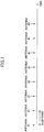
- antenna #1 is selected for data transmission in a user apparatus including two antennas #1, #2 is described with reference to FIG. 1 .
- a reference signal sounding reference signal
- the antennas for transmitting the reference signals are switched at a predefined pitch.
- the antennas for transmitting the reference signals may be switched once in four subframes.
- the sounding reference signals are transmitted from an antenna assigned for data transmissions in three of the four subframes but from an antenna not assigned for data transmissions in the remaining one subframe.
- the sounding reference signals are used for frequency scheduling in the antenna selected for data transmissions.
- the accuracy of the scheduling will become lower.
- the number of transmissions of the sounding reference signals from the antenna #2 not selected for data transmissions is reduced, the number of antenna switches will be reduced. In particular, communication quality becomes lower in cases of short fading pitches and frequent antenna switches.
- antennas are frequently switched to one with a better receive quality.
- antenna #1 has a better receive quality.
- antenna #2 has a better receive quality.
- antenna #1 has a better receive quality.
- antenna #2 has a better receive quality.
- the data transmission will be made from the selected antenna #1 even in a time period with a poor receive quality, which is not desirable.
- antenna #1 has a better receive quality
- antenna #2 has a better receive quality
- One object of the present invention is to provide a base station apparatus, a user apparatus and a communication control method that can properly control antenna switch pitches of transmitting reference signals in a mobile communication system where transmit diversity is applied.
- the antenna switch pitch of transmitting reference signals can be determined and transmitted based on the receive level of the reference signals transmitted from the user apparatus.
- a further technical example relates to a user apparatus in a radio communication system where transmit diversity is applied in uplinks, wherein an antenna switch pitch of transmitting a reference signal is determined in a base station apparatus based on a receive level of the reference signal transmitted in an uplink and is transmitted to the user apparatus, the user apparatus comprising: multiple antennas; and an antenna switch unit configured to switch among the antennas to transmit the reference signal based on the antenna switch pitch.
- transmit diversity by switching among the antennas transmitting reference signals can be applied in accordance with the antenna switch pitch of transmitting reference signals as determined in the base station apparatus.
- a still further technical example relates to a communication control method in a radio communication system where transmit diversity is applied in an uplink, the method comprising: a user apparatus switching among multiple antennas in accordance with an antenna switch pitch transmitted from a base station apparatus and transmitting a reference signal; the base station apparatus measuring a receive level of the reference signal; the base station apparatus determining an antenna switch pitch of transmitting a reference signal based on the measured receive level; and the base station apparatus transmitting the determined antenna switch pitch to the user apparatus.
- the antenna switch pitch of transmitting reference signals can be determined and transmitted based on the receive level of the reference signals transmitted from the user apparatus.
- a base station apparatus a user apparatus and a communication control method that can properly control antenna switch pitches of transmitting reference signals in a mobile communication system where transmit diversity is applied.
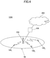
- a radio communication system to which a base station apparatus according to embodiments of the present invention is applied is described with reference to FIG. 4 .
- the radio communication system 1000 uses the OFDM scheme for downlinks and the SC-FDMA scheme for uplinks.
- the OFDM scheme is a scheme where a frequency band is segmented into smaller frequency bands (subcarriers) and data is transferred over the individual frequency bands.
- the SC-FDMA is a scheme where a frequency band is segmented and segmented different frequency bands are used among multiple terminals for transmission, resulting in reduction in interference among the terminals.
- the LTE uplink control channel is used to transmit downlink quality information (CQI: Channel Quality Indicator) used for scheduling of the PDSCH, AMC (Adaptive Modulation and Coding) and TPC (Transmit Power Control) and acknowledgement information for the PDSCH (HARQ ACK information).
- CQI Channel Quality Indicator
- AMC Adaptive Modulation and Coding
- TPC Transmit Power Control
- acknowledgement information for the PDSCH HARQ ACK information
- the PUSCH is used to transmit user data.
- TTI Transmit Time Interval
- LBs Long Term Evolution
- TTI Transmit Time Interval
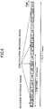
- one TTI consists of 14 long blocks as illustrated in FIG. 5 .
- Demodulation reference signals are mapped into two of the 14 long blocks.
- Sounding reference signals used to determine a transmit format for the PUSCH such as scheduling, uplink AMC and TPC are transmitted in one of the 14 long blocks other than the long blocks mapped into the demodulation reference signals.
- each user apparatus 100 n transmits data on a per-RB (Resource Block) basis with respect to the frequency direction and on a per-TTI basis with respect to the time direction.
- RB Resource Block
- one RB corresponds to 180 kHz.
- Receiving operations on the sounding reference signals are performed in the receiving RF unit 206, and the resulting signals are supplied to the reference signal measurement unit 208.
- the switch pitch of switching antennas to transmit sounding reference signals is made longer.
- the ASTD may be stopped. For example, when the fading pitch becomes less than a fading pitch corresponding to the migration speed of disabling the base station apparatus to follow the user apparatus 100 n in accordance with the closed loop control, for example, when the fading pitch becomes less than two subframes, the switch pitch of switching antennas to transmit sounding reference signals is made longer or the ASTD is stopped.
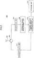
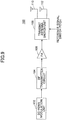
- the user apparatus 100 includes a SC-FDMA modulation unit 102, a RF transmitter circuit 104, a power amplifier (PA) 106, a transmit antenna switch unit 108 and antennas 110, 112.
- a switch pitch (reference signal switch pitch) of switching the antennas to transmit reference signals transmitted from the base station apparatus 200 is supplied to the transmit antenna switch unit 108.
- Base-banded sounding reference signals are supplied to the SC-FDMA modulation unit 102 for modulation in accordance with the SC-FDMA scheme. Then, the resulting signals are supplied to the RF transmitter circuit 104.
- the RF transmitter circuit 104 converts the modulated sounding reference signals into RF signals corresponding to a predefined uplink transmit frequency.
- the converted RF signals are amplified in the PA 106.
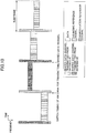
- reference signals may be transmitted from the antennas alternately in accordance with the reference signal switch pitch transmitted from the base station apparatus 200 regardless of which of the antennas is selected to transmit shared data channels.
- the antennas for transmitting sounding reference signals are alternated per one subframe.
- the reference signal switch pitch is equal to 4 (subframes)
- the remainder is equal to any of 0, 1 and 2
- the remainder is equal to 3
- the sounding reference signals are transmitted from the antenna assigned for data transmission in subframes #1, #2.
- the sounding reference signals are transmitted from the antenna not assigned for data transmissions
- subframe #4 the sounding reference signals are transmitted from the antenna assigned for data transmissions. For example, if antenna #1 is assigned for data transmission and antenna #2 is assigned for data transmissions in subframe #3, the sounding reference signals are transmitted in subframe #4 from antenna #2 assigned for data transmissions.
- a transmitter and a receiver that is, the base station apparatus 200 and the user apparatus, both know only the transmit antenna switch pattern for transmitting the reference signals, that is, reference signal transmit antenna switch pitch, no additional transmit control information is required.
- the reference signal measurement unit 208 measures a receive level, such as CQI, of a reference signal (sounding reference signal) transmitted from the user apparatus 100 n .
- the transmit antenna switch pitch determination unit 210 determines a switch pitch of switching antennas to transmit reference signals based on the fading pitch.
- a radio communication system, a base station apparatus and a user apparatus according to this embodiment have the same arrangements as those described in conjunction with FIGS. 4 , 7 and 9 and are not repeatedly described.
- a receive strength (receive level) of reference signals is measured at the reference signal measurement unit 208 and supplied to the transmit antenna switch pitch determination unit 210.
- the transmit antenna switch pitch determination unit 210 determines a transmit antenna switch pitch with reference to a table indicative of correspondence between receive strengths of the reference signals and transmit antenna switch pitches for sounding reference signals stored in the storage unit 212.
- the transmit antenna switch pitch determination unit 210 supplies the determined transmit antenna switch pitch to the transmitting RF unit 214.
- the transmitting RF unit 214 transmits the incoming transmit antenna switch pitch via the transmitting and receiving unit 204.
- the transmitting RF unit 214 may use downlink channels, such as L1/L2 downlink control channels or dedicated channels, to transmit the transmit antenna switch pitch to the user apparatus 100 n .
- the storage unit 212 stores the table indicative of the correspondence between the reference signal receive strengths and the transmit antenna switch pitches for sounding reference signals. Since it can be determined that the user apparatus 100 n associated with a lower reference signal receive strength may reside near the cell edge, the table is generated such that the transmit antenna switch pitch can be shorter for that user apparatus 100 n . On the other hand, since it can be determined that the user apparatus 100 n associated with a higher reference signal receive strength may reside near the cell center, the table is generated such that the transmit antenna switch pitch can be longer for that user apparatus 100 n .
- the reference signal transmit antenna switch pitch is made longer.
- the ASTD may be stopped.
- the reference signal measurement unit 208 measures a receive strength (receive level) of reference signals transmitted from the user apparatus 100 n .
- the transmit antenna switch pitch determination unit 210 determines a transmit antenna switch pitch for reference signals based on the measured receive strength of reference signals.
- the transmit antenna switch pitch determination unit 210 transmits the determined reference signal transmit antenna switch pitch to the user apparatus 100 n via the transmitting RF unit 214.
- the position of the user apparatus 100 n within a cell is determined through uplink reference signals transmitted from the user apparatus 100 n .
- the position of the user apparatus 100 n within the cell may be determined through other measures such as measured receive strengths of shared data channels or command values of TPC (Transmit Power Control).
- the base station apparatus 200 determines migration speed of the user apparatus 100 n based on uplink reference signals transmitted from the user apparatus 100 n and adjusts the transmit antenna switch pitch (transmit pattern) for transmitting reference signals with reference to a predefined correspondence table based on the determined migration speed.
- the base station apparatus 200 determines the position of the user apparatus 100 n within a cell based on measured receive strengths of uplink reference signals and/or shared data channels transmitted from the user apparatus 100 n or TPC command values and adjusts the reference signal transmit antenna switch pitch (transmit pattern) with reference to a predefined correspondence table.
- the base station apparatus 200 may not determine the reference signal transmit antenna switch pitch.
- the user apparatus 100 n may determine the migration speed and/or the position within a cell of the user apparatus 100 n and adjust the reference signal transmit antenna switch pitch (transmit pattern) with reference to a predefined correspondence table. For example, the user apparatus 100 n may determine the migration speed based on a fading fluctuation speed estimated from downlink reference signals, the migration speed estimated by GPS (Global Positioning System) in the user apparatus 100 n or others.
- GPS Global Positioning System
- the user apparatus 100 n may determine the position of the user apparatus 100 n within a cell based on path loss from the base station apparatus 200 connected to the user apparatus 100 n , a measured ratio of the path loss of the connected base station apparatus 200 to path loss of an adjacent or neighboring base station apparatus to the base station apparatus 200, matching between geographic information obtained through the GPS and possessed position information of the base station apparatus 200, the TPC command values or others.
- the determined results are transmitted to the base station apparatus 200 in uplink channels or uplink dedicated control channels.
- a base station apparatus in a radio communication system where transmit diversity is applied in uplinks, wherein a user apparatus including multiple antennas switches among the antennas in accordance with an antenna switch pitch transmitted from the base station apparatus and transmits a reference signal in an uplink, the base station apparatus comprising a reference signal measurement unit configured to measure a receive level of the reference signal; a switch pitch determination unit configured to determine the antenna switch pitch of transmitting the reference signal based on the receive level measured by the reference signal measurement unit; and a transmitting unit configured to transmit the antenna switch pitch determined by the switch pitch determination unit.
- the base station apparatus further comprising: a table indicating correspondence between receive levels of the reference signal and antenna switch pitches of transmitting a sounding reference signal, wherein the switch pitch determination unit is configured to determine the antenna switch pitch of transmitting the reference signal based on the table.
- a lower receive level corresponds to a shorter antenna switch frequency of transmitting the reference signal in the table.
- the switch pitch determination unit is configured to make an antenna switch pitch of transmitting a sounding reference signal longer or stop antenna selection transmit diversity.
- the base station apparatus further comprising: a fading pitch measurement unit configured to determine a fading pitch based on the receive level of the reference signal; and a table indicating correspondence between fading pitches and antenna switch pitches of transmitting a sounding reference signal, wherein the switch pitch determination unit is configured to determine the antenna switch pitch of transmitting the reference signal based on the table.
- a shorter fading pitch corresponds to a shorter antenna switch pitch of transmitting the reference signal in the table.
- the switch pitch determination unit is configured to make an antenna switch pitch of transmitting a sounding reference signal longer or stop antenna selection transmit diversity.
- a user apparatus in a radio communication system where transmit diversity is applied in uplinks, wherein an antenna switch pitch of transmitting a reference signal is determined in a base station apparatus based on a receive level of the reference signal transmitted in an uplink and is transmitted to the user apparatus, the user apparatus comprising: multiple antennas; and an antenna switch unit configured to switch among the antennas to transmit the reference signal based on the antenna switch pitch.
- a communication control method in a radio communication system where transmit diversity is applied in an uplink comprising: a user apparatus switching among multiple antennas in accordance with an antenna switch pitch transmitted from a base station apparatus and transmitting a reference signal; the base station apparatus measuring a receive level of the reference signal; the base station apparatus determining an antenna switch pitch of transmitting a reference signal based on the measured receive level; and the base station apparatus transmitting the determined antenna switch pitch to the user apparatus.
Landscapes
- Engineering & Computer Science (AREA)
- Computer Networks & Wireless Communication (AREA)
- Signal Processing (AREA)
- Radio Transmission System (AREA)
- Mobile Radio Communication Systems (AREA)
Applications Claiming Priority (2)
| Application Number | Priority Date | Filing Date | Title |
|---|---|---|---|
| JP2007034133A JP4869972B2 (ja) | 2007-02-14 | 2007-02-14 | ユーザ装置、送信方法、及び無線通信システム |
| EP08711016.9A EP2129005A4 (en) | 2007-02-14 | 2008-02-08 | BASIC STATION EQUIPMENT, USER EQUIPMENT AND COMMUNICATION CONTROL METHOD |
Related Parent Applications (2)
| Application Number | Title | Priority Date | Filing Date |
|---|---|---|---|
| EP08711016.9 Division | 2008-02-08 | ||
| EP08711016.9A Division EP2129005A4 (en) | 2007-02-14 | 2008-02-08 | BASIC STATION EQUIPMENT, USER EQUIPMENT AND COMMUNICATION CONTROL METHOD |
Publications (2)
| Publication Number | Publication Date |
|---|---|
| EP2683096A1 EP2683096A1 (en) | 2014-01-08 |
| EP2683096B1 true EP2683096B1 (en) | 2017-08-23 |
Family
ID=39690013
Family Applications (2)
| Application Number | Title | Priority Date | Filing Date |
|---|---|---|---|
| EP13186821.8A Active EP2683096B1 (en) | 2007-02-14 | 2008-02-08 | Base station apparatus, user apparatus and communication control method |
| EP08711016.9A Withdrawn EP2129005A4 (en) | 2007-02-14 | 2008-02-08 | BASIC STATION EQUIPMENT, USER EQUIPMENT AND COMMUNICATION CONTROL METHOD |
Family Applications After (1)
| Application Number | Title | Priority Date | Filing Date |
|---|---|---|---|
| EP08711016.9A Withdrawn EP2129005A4 (en) | 2007-02-14 | 2008-02-08 | BASIC STATION EQUIPMENT, USER EQUIPMENT AND COMMUNICATION CONTROL METHOD |
Country Status (8)
| Country | Link |
|---|---|
| US (2) | US8463203B2 (enExample) |
| EP (2) | EP2683096B1 (enExample) |
| JP (1) | JP4869972B2 (enExample) |
| KR (1) | KR101340379B1 (enExample) |
| CN (2) | CN101657979B (enExample) |
| BR (1) | BRPI0808128A2 (enExample) |
| RU (1) | RU2456744C2 (enExample) |
| WO (1) | WO2008099780A1 (enExample) |
Families Citing this family (22)
| Publication number | Priority date | Publication date | Assignee | Title |
|---|---|---|---|---|
| WO2009019879A1 (ja) | 2007-08-08 | 2009-02-12 | Panasonic Corporation | 無線通信基地局装置および関連付け設定方法 |
| WO2009099024A1 (ja) * | 2008-02-05 | 2009-08-13 | Sharp Kabushiki Kaisha | 移動通信装置、基地局装置、無線制御方法、及び移動通信システム |
| MX2010013250A (es) * | 2008-06-06 | 2010-12-21 | Sharp Kk | Sistema de comunicacion movil, dispositivo de comunicacion movil y metodo de comunicacion movil. |
| EP3327982B1 (en) * | 2008-06-23 | 2019-08-07 | Sun Patent Trust | Method of arranging reference signals and wireless communication system |
| US8811513B2 (en) * | 2010-02-05 | 2014-08-19 | Qualcomm Incorporated | Antenna switching in a closed loop transmit diversity system |
| JP5291664B2 (ja) * | 2010-04-30 | 2013-09-18 | 株式会社エヌ・ティ・ティ・ドコモ | データ送信方法、基地局装置及び移動局装置 |
| US8891387B2 (en) * | 2010-05-03 | 2014-11-18 | Qualcomm Incorporated | UE based conditional enabling of ULTD |
| JP5574872B2 (ja) * | 2010-08-03 | 2014-08-20 | シャープ株式会社 | 基地局装置、移動局装置、および、通信方法 |
| US8416741B2 (en) * | 2010-09-07 | 2013-04-09 | Verizon Patent And Licensing Inc. | Machine-to-machine communications over fixed wireless networks |
| WO2012108802A1 (en) * | 2011-02-07 | 2012-08-16 | Telefonaktiebolaget L M Ericsson (Publ) | Base station (antenna) selection for uplink transmission of sounding reference signals, srs |
| US9401791B2 (en) * | 2011-05-10 | 2016-07-26 | Lg Electronics Inc. | Method for transmitting signal using plurality of antenna ports and transmission end apparatus for same |
| US9379789B2 (en) * | 2013-07-03 | 2016-06-28 | Qualcomm Incorporated | Antenna selection adjustment |
| US10057906B2 (en) | 2014-02-28 | 2018-08-21 | Lg Electronics Inc. | Method and apparatus for generating signal for low latency in wireless communication system |
| JP6466973B2 (ja) * | 2014-06-24 | 2019-02-06 | テレフオンアクチーボラゲット エルエム エリクソン(パブル) | ワイヤレス通信ネットワークを動作させる方法および装置 |
| CN107534533B (zh) | 2015-05-22 | 2020-09-18 | 富士通株式会社 | 参考信号的资源配置方法、装置以及通信系统 |
| US11272387B2 (en) * | 2017-02-15 | 2022-03-08 | Telefonaktiebolaget Lm Ericsson (Publ) | Managing communication in a wireless communication network |
| US10320517B2 (en) | 2017-06-05 | 2019-06-11 | J3 Technology LLC | Switched transmit antennas with no feedback for multipath reduction |
| JP2021182655A (ja) | 2018-08-09 | 2021-11-25 | ソニーグループ株式会社 | 通信装置、通信制御方法及び記録媒体 |
| CN111405663A (zh) * | 2019-01-03 | 2020-07-10 | 索尼公司 | 用于无线通信的电子设备和方法、计算机可读存储介质 |
| WO2020214071A1 (en) * | 2019-04-17 | 2020-10-22 | Telefonaktiebolaget Lm Ericsson (Publ) | Radio network node and method for reducing energy consumption in a wireless communications network |
| US11374633B2 (en) * | 2019-11-21 | 2022-06-28 | Qualcomm Incorporated | Low cost power efficient antenna switch diversity and cyclic delay diversity transceiver |
| CN112583504B (zh) * | 2020-12-16 | 2022-09-06 | 维沃移动通信有限公司 | 天线切换方法及装置 |
Family Cites Families (27)
| Publication number | Priority date | Publication date | Assignee | Title |
|---|---|---|---|---|
| JP2650297B2 (ja) * | 1988-01-30 | 1997-09-03 | ソニー株式会社 | アンテナ切換方法 |
| JPH07162350A (ja) * | 1993-12-07 | 1995-06-23 | Hitachi Ltd | ダイバーシティ受信装置 |
| US5541963A (en) * | 1993-12-01 | 1996-07-30 | Hitachi, Ltd. | Diversity receiving apparatus |
| DE19546599C2 (de) * | 1995-12-13 | 1999-07-29 | Siemens Ag | Sendeeinrichtung |
| US5692019A (en) * | 1996-06-17 | 1997-11-25 | Motorola, Inc. | Communication device having antenna switch diversity, and method therefor |
| JPH11252614A (ja) | 1998-03-05 | 1999-09-17 | Kokusai Electric Co Ltd | 通信システム及び基地局装置及び移動局装置 |
| KR20000002504A (ko) | 1998-06-20 | 2000-01-15 | 윤종용 | 이동통신 시스템의 선택적 송신 다이버시티 장치 및 방법 |
| JP3583304B2 (ja) * | 1998-11-18 | 2004-11-04 | 松下電器産業株式会社 | 通信端末装置、基地局装置及び送信アンテナ切替方法 |
| JP2001196928A (ja) | 2000-01-13 | 2001-07-19 | Hitachi Ltd | A/d変換処理装置 |
| FR2810456B1 (fr) * | 2000-06-20 | 2005-02-11 | Mitsubishi Electric Inf Tech | Dispositif d'antenne reconfigurable pour station de telecommunication |
| DE60122530T2 (de) * | 2001-10-09 | 2007-04-05 | Lucent Technologies Inc. | Verfahren und Vorrichtung zum Erzeugen von einer Diversityübertragung in drahtlosen Kommunikationssystemen anhand von Antennenhopping-Sequenzen und/oder Polarisationshopping-Sequencen |
| JP3796188B2 (ja) | 2002-04-09 | 2006-07-12 | パナソニック モバイルコミュニケーションズ株式会社 | Ofdm通信方法およびofdm通信装置 |
| CN1281084C (zh) * | 2002-11-04 | 2006-10-18 | 中兴通讯股份有限公司 | 一种实时天线选择发射分集方法及装置 |
| DE60305637T2 (de) * | 2003-03-19 | 2007-05-03 | Sony Ericsson Mobile Communications Ab | Schaltbare Antennenanordnung |
| JP2004320528A (ja) * | 2003-04-17 | 2004-11-11 | Mitsubishi Electric Corp | ダイバーシチ受信装置 |
| KR20050032809A (ko) * | 2003-10-02 | 2005-04-08 | 삼성전자주식회사 | 시분할-부호분할 다중접속 이동통신 시스템에서 빔포밍수행 장치 및 방법 |
| US7039370B2 (en) * | 2003-10-16 | 2006-05-02 | Flarion Technologies, Inc. | Methods and apparatus of providing transmit and/or receive diversity with multiple antennas in wireless communication systems |
| JP4396379B2 (ja) * | 2004-04-23 | 2010-01-13 | 日本電気株式会社 | 受信ダイバーシティシステムおよびその制御方法 |
| JP2006067237A (ja) * | 2004-08-26 | 2006-03-09 | Sharp Corp | 無線送信機および無線受信機 |
| US20060111054A1 (en) * | 2004-11-22 | 2006-05-25 | Interdigital Technology Corporation | Method and system for selecting transmit antennas to reduce antenna correlation |
| US7573851B2 (en) * | 2004-12-07 | 2009-08-11 | Adaptix, Inc. | Method and system for switching antenna and channel assignments in broadband wireless networks |
| WO2006104029A1 (ja) * | 2005-03-28 | 2006-10-05 | Matsushita Electric Industrial Co., Ltd. | 受信端末 |
| JP2006279450A (ja) * | 2005-03-29 | 2006-10-12 | Clarion Co Ltd | 車載用デジタルテレビ受信装置 |
| JP4812357B2 (ja) | 2005-07-29 | 2011-11-09 | 株式会社Suwaオプトロニクス | 小径カメラ |
| US8116412B1 (en) * | 2006-12-30 | 2012-02-14 | Rockstar Bidco, LP | Modulation division multiple access |
| US7697623B2 (en) * | 2007-01-05 | 2010-04-13 | Mitsubishi Electric Research Laboratories, Inc. | Method and system for switching antennas during transmission time intervals in OFDMA systems |
| US8774736B2 (en) * | 2007-02-02 | 2014-07-08 | Lg Electronics Inc. | Antenna switching for data transmission in a communication system using a plurality of transmission antennas |
-
2007
- 2007-02-14 JP JP2007034133A patent/JP4869972B2/ja not_active Expired - Fee Related
-
2008
- 2008-02-08 US US12/526,729 patent/US8463203B2/en not_active Expired - Fee Related
- 2008-02-08 RU RU2009133104/07A patent/RU2456744C2/ru not_active IP Right Cessation
- 2008-02-08 CN CN2008800120504A patent/CN101657979B/zh active Active
- 2008-02-08 CN CN201310424721.0A patent/CN103763013B/zh active Active
- 2008-02-08 KR KR1020097018796A patent/KR101340379B1/ko not_active Expired - Fee Related
- 2008-02-08 BR BRPI0808128-0A2A patent/BRPI0808128A2/pt not_active IP Right Cessation
- 2008-02-08 EP EP13186821.8A patent/EP2683096B1/en active Active
- 2008-02-08 WO PCT/JP2008/052137 patent/WO2008099780A1/ja not_active Ceased
- 2008-02-08 EP EP08711016.9A patent/EP2129005A4/en not_active Withdrawn
-
2013
- 2013-04-15 US US13/862,995 patent/US9369996B2/en active Active
Non-Patent Citations (1)
| Title |
|---|
| None * |
Also Published As
| Publication number | Publication date |
|---|---|
| EP2129005A1 (en) | 2009-12-02 |
| RU2009133104A (ru) | 2011-03-20 |
| CN103763013B (zh) | 2017-01-18 |
| WO2008099780A1 (ja) | 2008-08-21 |
| JP2008199424A (ja) | 2008-08-28 |
| CN101657979B (zh) | 2013-10-30 |
| US20100056074A1 (en) | 2010-03-04 |
| KR101340379B1 (ko) | 2013-12-13 |
| EP2129005A4 (en) | 2013-12-11 |
| RU2456744C2 (ru) | 2012-07-20 |
| CN103763013A (zh) | 2014-04-30 |
| BRPI0808128A2 (pt) | 2014-06-17 |
| US9369996B2 (en) | 2016-06-14 |
| US20130223415A1 (en) | 2013-08-29 |
| KR20090110871A (ko) | 2009-10-22 |
| JP4869972B2 (ja) | 2012-02-08 |
| EP2683096A1 (en) | 2014-01-08 |
| CN101657979A (zh) | 2010-02-24 |
| US8463203B2 (en) | 2013-06-11 |
Similar Documents
| Publication | Publication Date | Title |
|---|---|---|
| EP2683096B1 (en) | Base station apparatus, user apparatus and communication control method | |
| US12126437B2 (en) | Channel state information reporting on licensed and unlicensed carriers | |
| US8208435B2 (en) | Base station apparatus, user apparatus and method for use in mobile communication system | |
| EP3214885B1 (en) | Apparatus and method for feeding back channel quality information and scheduling apparatus and method using the same in a wireless communication system | |
| KR101387857B1 (ko) | 무선 통신 장치, 기지국 및 그것의 안테나 포트 모드 및 송신 모드 이행을 위한 방법 | |
| EP2721743B1 (en) | Feedback method and apparatus for cooperative communication system | |
| EP2918091B1 (en) | Transmission mode selection and downlink scheduling using primary and dedicated pilot signals | |
| EP2487945A1 (en) | Base station device and user device | |
| KR20100113568A (ko) | 릴레이 전송 시스템, 기지국, 중계국 및 방법 | |
| CA2557040A1 (en) | Method and apparatus for transmitting/receiving channel quality information in a communication system using an orthogonal frequency division multiplexing scheme | |
| CN104980260A (zh) | 激活/去激活多个次级载波的方法、wtru及处理drx/dtx的方法 | |
| KR20090106504A (ko) | 이동통신시스템에서 사용되는 기지국장치, 유저장치 및 방법 | |
| CN113169779A (zh) | 基站装置、终端装置以及通信方法 | |
| KR20120096411A (ko) | 단말 및 그 단말에서 랜덤 억세스 수행을 위한 전력 제어 방법 | |
| US9485067B2 (en) | Pilot arrangement method in mobile radio communication system and transmitter/receiver adopting same | |
| EP2187539B1 (en) | Base station apparatus and uplink sinr measuring method | |
| US9288811B2 (en) | Base station device and mobile communication method | |
| EP2487974A1 (en) | Base station apparatus and mobile communication method | |
| JP5133383B2 (ja) | 基地局装置及び受信方法 | |
| JP2012129811A (ja) | 無線基地局装置 | |
| EP2437410A1 (en) | Radio network control |
Legal Events
| Date | Code | Title | Description |
|---|---|---|---|
| PUAI | Public reference made under article 153(3) epc to a published international application that has entered the european phase |
Free format text: ORIGINAL CODE: 0009012 |
|
| 17P | Request for examination filed |
Effective date: 20131001 |
|
| AC | Divisional application: reference to earlier application |
Ref document number: 2129005 Country of ref document: EP Kind code of ref document: P |
|
| AK | Designated contracting states |
Kind code of ref document: A1 Designated state(s): AT BE BG CH CY CZ DE DK EE ES FI FR GB GR HR HU IE IS IT LI LT LU LV MC MT NL NO PL PT RO SE SI SK TR |
|
| 17Q | First examination report despatched |
Effective date: 20140403 |
|
| GRAP | Despatch of communication of intention to grant a patent |
Free format text: ORIGINAL CODE: EPIDOSNIGR1 |
|
| INTG | Intention to grant announced |
Effective date: 20170405 |
|
| RAP1 | Party data changed (applicant data changed or rights of an application transferred) |
Owner name: NTT DOCOMO, INC. |
|
| GRAS | Grant fee paid |
Free format text: ORIGINAL CODE: EPIDOSNIGR3 |
|
| GRAA | (expected) grant |
Free format text: ORIGINAL CODE: 0009210 |
|
| AC | Divisional application: reference to earlier application |
Ref document number: 2129005 Country of ref document: EP Kind code of ref document: P |
|
| AK | Designated contracting states |
Kind code of ref document: B1 Designated state(s): AT BE BG CH CY CZ DE DK EE ES FI FR GB GR HR HU IE IS IT LI LT LU LV MC MT NL NO PL PT RO SE SI SK TR |
|
| REG | Reference to a national code |
Ref country code: GB Ref legal event code: FG4D |
|
| REG | Reference to a national code |
Ref country code: CH Ref legal event code: EP |
|
| REG | Reference to a national code |
Ref country code: AT Ref legal event code: REF Ref document number: 922346 Country of ref document: AT Kind code of ref document: T Effective date: 20170915 |
|
| REG | Reference to a national code |
Ref country code: IE Ref legal event code: FG4D |
|
| REG | Reference to a national code |
Ref country code: DE Ref legal event code: R096 Ref document number: 602008051841 Country of ref document: DE |
|
| REG | Reference to a national code |
Ref country code: NL Ref legal event code: MP Effective date: 20170823 |
|
| REG | Reference to a national code |
Ref country code: LT Ref legal event code: MG4D |
|
| PG25 | Lapsed in a contracting state [announced via postgrant information from national office to epo] |
Ref country code: LT Free format text: LAPSE BECAUSE OF FAILURE TO SUBMIT A TRANSLATION OF THE DESCRIPTION OR TO PAY THE FEE WITHIN THE PRESCRIBED TIME-LIMIT Effective date: 20170823 Ref country code: HR Free format text: LAPSE BECAUSE OF FAILURE TO SUBMIT A TRANSLATION OF THE DESCRIPTION OR TO PAY THE FEE WITHIN THE PRESCRIBED TIME-LIMIT Effective date: 20170823 Ref country code: FI Free format text: LAPSE BECAUSE OF FAILURE TO SUBMIT A TRANSLATION OF THE DESCRIPTION OR TO PAY THE FEE WITHIN THE PRESCRIBED TIME-LIMIT Effective date: 20170823 Ref country code: NL Free format text: LAPSE BECAUSE OF FAILURE TO SUBMIT A TRANSLATION OF THE DESCRIPTION OR TO PAY THE FEE WITHIN THE PRESCRIBED TIME-LIMIT Effective date: 20170823 Ref country code: SE Free format text: LAPSE BECAUSE OF FAILURE TO SUBMIT A TRANSLATION OF THE DESCRIPTION OR TO PAY THE FEE WITHIN THE PRESCRIBED TIME-LIMIT Effective date: 20170823 Ref country code: NO Free format text: LAPSE BECAUSE OF FAILURE TO SUBMIT A TRANSLATION OF THE DESCRIPTION OR TO PAY THE FEE WITHIN THE PRESCRIBED TIME-LIMIT Effective date: 20171123 |
|
| PG25 | Lapsed in a contracting state [announced via postgrant information from national office to epo] |
Ref country code: BG Free format text: LAPSE BECAUSE OF FAILURE TO SUBMIT A TRANSLATION OF THE DESCRIPTION OR TO PAY THE FEE WITHIN THE PRESCRIBED TIME-LIMIT Effective date: 20171123 Ref country code: ES Free format text: LAPSE BECAUSE OF FAILURE TO SUBMIT A TRANSLATION OF THE DESCRIPTION OR TO PAY THE FEE WITHIN THE PRESCRIBED TIME-LIMIT Effective date: 20170823 Ref country code: LV Free format text: LAPSE BECAUSE OF FAILURE TO SUBMIT A TRANSLATION OF THE DESCRIPTION OR TO PAY THE FEE WITHIN THE PRESCRIBED TIME-LIMIT Effective date: 20170823 Ref country code: IS Free format text: LAPSE BECAUSE OF FAILURE TO SUBMIT A TRANSLATION OF THE DESCRIPTION OR TO PAY THE FEE WITHIN THE PRESCRIBED TIME-LIMIT Effective date: 20171223 Ref country code: PL Free format text: LAPSE BECAUSE OF FAILURE TO SUBMIT A TRANSLATION OF THE DESCRIPTION OR TO PAY THE FEE WITHIN THE PRESCRIBED TIME-LIMIT Effective date: 20170823 |
|
| REG | Reference to a national code |
Ref country code: GR Ref legal event code: EP Ref document number: 20170402526 Country of ref document: GR Effective date: 20180309 |
|
| PG25 | Lapsed in a contracting state [announced via postgrant information from national office to epo] |
Ref country code: DK Free format text: LAPSE BECAUSE OF FAILURE TO SUBMIT A TRANSLATION OF THE DESCRIPTION OR TO PAY THE FEE WITHIN THE PRESCRIBED TIME-LIMIT Effective date: 20170823 Ref country code: RO Free format text: LAPSE BECAUSE OF FAILURE TO SUBMIT A TRANSLATION OF THE DESCRIPTION OR TO PAY THE FEE WITHIN THE PRESCRIBED TIME-LIMIT Effective date: 20170823 Ref country code: CZ Free format text: LAPSE BECAUSE OF FAILURE TO SUBMIT A TRANSLATION OF THE DESCRIPTION OR TO PAY THE FEE WITHIN THE PRESCRIBED TIME-LIMIT Effective date: 20170823 |
|
| REG | Reference to a national code |
Ref country code: DE Ref legal event code: R097 Ref document number: 602008051841 Country of ref document: DE |
|
| PG25 | Lapsed in a contracting state [announced via postgrant information from national office to epo] |
Ref country code: EE Free format text: LAPSE BECAUSE OF FAILURE TO SUBMIT A TRANSLATION OF THE DESCRIPTION OR TO PAY THE FEE WITHIN THE PRESCRIBED TIME-LIMIT Effective date: 20170823 Ref country code: SK Free format text: LAPSE BECAUSE OF FAILURE TO SUBMIT A TRANSLATION OF THE DESCRIPTION OR TO PAY THE FEE WITHIN THE PRESCRIBED TIME-LIMIT Effective date: 20170823 Ref country code: IT Free format text: LAPSE BECAUSE OF FAILURE TO SUBMIT A TRANSLATION OF THE DESCRIPTION OR TO PAY THE FEE WITHIN THE PRESCRIBED TIME-LIMIT Effective date: 20170823 |
|
| PLBE | No opposition filed within time limit |
Free format text: ORIGINAL CODE: 0009261 |
|
| STAA | Information on the status of an ep patent application or granted ep patent |
Free format text: STATUS: NO OPPOSITION FILED WITHIN TIME LIMIT |
|
| 26N | No opposition filed |
Effective date: 20180524 |
|
| PG25 | Lapsed in a contracting state [announced via postgrant information from national office to epo] |
Ref country code: SI Free format text: LAPSE BECAUSE OF FAILURE TO SUBMIT A TRANSLATION OF THE DESCRIPTION OR TO PAY THE FEE WITHIN THE PRESCRIBED TIME-LIMIT Effective date: 20170823 |
|
| REG | Reference to a national code |
Ref country code: CH Ref legal event code: PL |
|
| PG25 | Lapsed in a contracting state [announced via postgrant information from national office to epo] |
Ref country code: MC Free format text: LAPSE BECAUSE OF FAILURE TO SUBMIT A TRANSLATION OF THE DESCRIPTION OR TO PAY THE FEE WITHIN THE PRESCRIBED TIME-LIMIT Effective date: 20170823 |
|
| REG | Reference to a national code |
Ref country code: IE Ref legal event code: MM4A |
|
| REG | Reference to a national code |
Ref country code: BE Ref legal event code: MM Effective date: 20180228 |
|
| PG25 | Lapsed in a contracting state [announced via postgrant information from national office to epo] |
Ref country code: CH Free format text: LAPSE BECAUSE OF NON-PAYMENT OF DUE FEES Effective date: 20180228 Ref country code: LI Free format text: LAPSE BECAUSE OF NON-PAYMENT OF DUE FEES Effective date: 20180228 Ref country code: LU Free format text: LAPSE BECAUSE OF NON-PAYMENT OF DUE FEES Effective date: 20180208 |
|
| REG | Reference to a national code |
Ref country code: FR Ref legal event code: ST Effective date: 20181031 |
|
| PG25 | Lapsed in a contracting state [announced via postgrant information from national office to epo] |
Ref country code: IE Free format text: LAPSE BECAUSE OF NON-PAYMENT OF DUE FEES Effective date: 20180208 |
|
| PG25 | Lapsed in a contracting state [announced via postgrant information from national office to epo] |
Ref country code: FR Free format text: LAPSE BECAUSE OF NON-PAYMENT OF DUE FEES Effective date: 20180228 Ref country code: BE Free format text: LAPSE BECAUSE OF NON-PAYMENT OF DUE FEES Effective date: 20180228 |
|
| PG25 | Lapsed in a contracting state [announced via postgrant information from national office to epo] |
Ref country code: MT Free format text: LAPSE BECAUSE OF NON-PAYMENT OF DUE FEES Effective date: 20180208 |
|
| PG25 | Lapsed in a contracting state [announced via postgrant information from national office to epo] |
Ref country code: TR Free format text: LAPSE BECAUSE OF FAILURE TO SUBMIT A TRANSLATION OF THE DESCRIPTION OR TO PAY THE FEE WITHIN THE PRESCRIBED TIME-LIMIT Effective date: 20170823 |
|
| PG25 | Lapsed in a contracting state [announced via postgrant information from national office to epo] |
Ref country code: PT Free format text: LAPSE BECAUSE OF FAILURE TO SUBMIT A TRANSLATION OF THE DESCRIPTION OR TO PAY THE FEE WITHIN THE PRESCRIBED TIME-LIMIT Effective date: 20170823 Ref country code: HU Free format text: LAPSE BECAUSE OF FAILURE TO SUBMIT A TRANSLATION OF THE DESCRIPTION OR TO PAY THE FEE WITHIN THE PRESCRIBED TIME-LIMIT; INVALID AB INITIO Effective date: 20080208 |
|
| PG25 | Lapsed in a contracting state [announced via postgrant information from national office to epo] |
Ref country code: CY Free format text: LAPSE BECAUSE OF FAILURE TO SUBMIT A TRANSLATION OF THE DESCRIPTION OR TO PAY THE FEE WITHIN THE PRESCRIBED TIME-LIMIT Effective date: 20170823 |
|
| REG | Reference to a national code |
Ref country code: AT Ref legal event code: UEP Ref document number: 922346 Country of ref document: AT Kind code of ref document: T Effective date: 20170823 |
|
| P01 | Opt-out of the competence of the unified patent court (upc) registered |
Effective date: 20230517 |
|
| PGFP | Annual fee paid to national office [announced via postgrant information from national office to epo] |
Ref country code: DE Payment date: 20250218 Year of fee payment: 18 |
|
| PGFP | Annual fee paid to national office [announced via postgrant information from national office to epo] |
Ref country code: GR Payment date: 20250220 Year of fee payment: 18 Ref country code: AT Payment date: 20250219 Year of fee payment: 18 |
|
| PGFP | Annual fee paid to national office [announced via postgrant information from national office to epo] |
Ref country code: GB Payment date: 20250219 Year of fee payment: 18 |