EP2682613A1 - Adhesive flange structure - Google Patents
Adhesive flange structure Download PDFInfo
- Publication number
- EP2682613A1 EP2682613A1 EP11859777.2A EP11859777A EP2682613A1 EP 2682613 A1 EP2682613 A1 EP 2682613A1 EP 11859777 A EP11859777 A EP 11859777A EP 2682613 A1 EP2682613 A1 EP 2682613A1
- Authority
- EP
- European Patent Office
- Prior art keywords
- flange
- vehicle body
- body panel
- bend portion
- bend
- Prior art date
- Legal status (The legal status is an assumption and is not a legal conclusion. Google has not performed a legal analysis and makes no representation as to the accuracy of the status listed.)
- Granted
Links
Images



Classifications
-
- B—PERFORMING OPERATIONS; TRANSPORTING
- B62—LAND VEHICLES FOR TRAVELLING OTHERWISE THAN ON RAILS
- B62D—MOTOR VEHICLES; TRAILERS
- B62D27/00—Connections between superstructure or understructure sub-units
- B62D27/02—Connections between superstructure or understructure sub-units rigid
- B62D27/026—Connections by glue bonding
-
- F—MECHANICAL ENGINEERING; LIGHTING; HEATING; WEAPONS; BLASTING
- F16—ENGINEERING ELEMENTS AND UNITS; GENERAL MEASURES FOR PRODUCING AND MAINTAINING EFFECTIVE FUNCTIONING OF MACHINES OR INSTALLATIONS; THERMAL INSULATION IN GENERAL
- F16B—DEVICES FOR FASTENING OR SECURING CONSTRUCTIONAL ELEMENTS OR MACHINE PARTS TOGETHER, e.g. NAILS, BOLTS, CIRCLIPS, CLAMPS, CLIPS OR WEDGES; JOINTS OR JOINTING
- F16B11/00—Connecting constructional elements or machine parts by sticking or pressing them together, e.g. cold pressure welding
-
- F—MECHANICAL ENGINEERING; LIGHTING; HEATING; WEAPONS; BLASTING
- F16—ENGINEERING ELEMENTS AND UNITS; GENERAL MEASURES FOR PRODUCING AND MAINTAINING EFFECTIVE FUNCTIONING OF MACHINES OR INSTALLATIONS; THERMAL INSULATION IN GENERAL
- F16B—DEVICES FOR FASTENING OR SECURING CONSTRUCTIONAL ELEMENTS OR MACHINE PARTS TOGETHER, e.g. NAILS, BOLTS, CIRCLIPS, CLAMPS, CLIPS OR WEDGES; JOINTS OR JOINTING
- F16B5/00—Joining sheets or plates, e.g. panels, to one another or to strips or bars parallel to them
- F16B5/08—Joining sheets or plates, e.g. panels, to one another or to strips or bars parallel to them by means of welds or the like
-
- F—MECHANICAL ENGINEERING; LIGHTING; HEATING; WEAPONS; BLASTING
- F16—ENGINEERING ELEMENTS AND UNITS; GENERAL MEASURES FOR PRODUCING AND MAINTAINING EFFECTIVE FUNCTIONING OF MACHINES OR INSTALLATIONS; THERMAL INSULATION IN GENERAL
- F16B—DEVICES FOR FASTENING OR SECURING CONSTRUCTIONAL ELEMENTS OR MACHINE PARTS TOGETHER, e.g. NAILS, BOLTS, CIRCLIPS, CLAMPS, CLIPS OR WEDGES; JOINTS OR JOINTING
- F16B11/00—Connecting constructional elements or machine parts by sticking or pressing them together, e.g. cold pressure welding
- F16B11/006—Connecting constructional elements or machine parts by sticking or pressing them together, e.g. cold pressure welding by gluing
-
- Y—GENERAL TAGGING OF NEW TECHNOLOGICAL DEVELOPMENTS; GENERAL TAGGING OF CROSS-SECTIONAL TECHNOLOGIES SPANNING OVER SEVERAL SECTIONS OF THE IPC; TECHNICAL SUBJECTS COVERED BY FORMER USPC CROSS-REFERENCE ART COLLECTIONS [XRACs] AND DIGESTS
- Y10—TECHNICAL SUBJECTS COVERED BY FORMER USPC
- Y10T—TECHNICAL SUBJECTS COVERED BY FORMER US CLASSIFICATION
- Y10T403/00—Joints and connections
- Y10T403/47—Molded joint
- Y10T403/477—Fusion bond, e.g., weld, etc.
Definitions
- the present invention relates to an adhesion flange structure.
- Structures include an upper side metal plate that is curved to form an upper wall portion and an upper side flange, and a lower side metal plate that is curved to form a lower wall portion and a lower side flange.
- the upper side flange and the lower side flange are joined together using an adhesive (see for example Japanese Patent Application Laid-Open (JP-A) No. 2006-167753 ).
- a subject of the present invention is to provide an adhesion flange structure capable of securing the rigidity of a bend portion.
- an adhesion flange structure of the present invention includes: a first flange extending along an end portion of a first vehicle body panel, and formed at the end portion of the first vehicle body panel with a bend portion interposed therebetween; a second flange formed at an end portion of a second vehicle body panel that configures a section of a vehicle body together with the first vehicle body panel, the second flange facing the bend portion and the first flange; an adhesive that adheres the bend portion and the first flange to the second flange; and a ridge projection portion formed extending along a direction in which the first flange extends at the end portion of the first vehicle body panel, and formed to at least one portion out of the bend portion and a facing portion of the second flange that faces the bend portion, the ridge projection portion forming a projection towards another portion out of the bend portion and the facing portion.
- the ridge projection portion is formed to at least one portion out of the bend portion and the facing portion of the second flange that faces the bend portion such that the ridge projection portion projects towards the other side out of the bend portion and the facing portion.
- the thickness of the adhesive between the bend portion and the facing portion can be reduced due to forming the ridge projection portion, thereby enabling the rigidity of the bend portion to be secured.
- configuration is preferably made wherein the ridge projection portion is formed at both the bend portion and the facing portion.
- the thickness of the adhesive between the bend portion and the facing portion can be reduced even further, thereby enabling the rigidity of the bend portion to be further secured.
- the present invention is capable of securing the rigidity of the bend portion.
- a vehicle framework member 30 illustrated in Fig. 1 configures a portion of a vehicle body, and includes a first vehicle body panel 32 and a second vehicle body panel 34.
- the first vehicle body panel 32 and the second vehicle body panel 34 are respectively configured by steel plates.
- the first vehicle body panel 32 is formed with a hat shaped cross-section profile open towards a second vehicle body panel 34 side.
- the second vehicle body panel 34 is formed in a flat plate shape, and forms a closed cross-section portion together with the first vehicle body panel 32.
- An adhesion flange structure 10 according to an exemplary embodiment of the present invention is applied to the first vehicle body panel 32 and the second vehicle body panel 34.
- the first vehicle body panel 32 is formed with a side wall portion 36 that projects up with respect to the second vehicle body panel 34.
- An end portion at a second vehicle body panel 34 side of the side wall portion 36 is formed with a first flange 14 with a bend portion 12 interposed therebetween.
- the first flange 14 extends in an L direction along the end portion at the second vehicle body panel 34 side of the side wall portion 36.
- An end portion at a first flange 14 side of the second vehicle body panel 34 is formed with a second flange 16 facing the bend portion 12 and the first flange 14.
- the bend portion 12 and the first flange 14 are adhered to the second flange 16 at substantially the entire region of the bend portion 12 and the first flange 14 using an adhesive 18.
- the first flange 14 and the second flange 16 are moreover joined together by spot welding at plural welding portions 20.
- the plural welding portions 20 extend in a row at intervals to each other along the extension direction of the first flange 14 along the end portion at the second vehicle body panel 34 side of the side wall portion 36, namely along the L direction.
- the bend portion 12 described above is formed with a ridge projection portion 24 that projects towards a facing portion 22 side of the second flange 16 that faces the bend portion 12.
- the ridge projection portion 24 extends along the L direction described above.
- adhesion flange structures 50, 60 of the Comparative Examples illustrated in Fig. 6 and Fig. 7 the ridge projection portion 24 of the adhesion flange structure 10 according to the exemplary embodiment described above is omitted.
- the first flange 14 is however bent towards a second flange 16 side due to contact by a spot gun during spot welding.
- the bend portion 12 is adhered to the second flange 16 in a floating state positioned a specific dimension or greater from the second flange 16.
- the thickness of the adhesive 18 between the bend portion 12 and the facing portion 22 accordingly increases, and the rigidity of the bend portion 12 cannot be secured.
- the bend portion 12 is adhered to the second flange 16 in a floating state positioned a specific dimension or greater from the second flange 16, and the rigidity of the bend portion 12 cannot be secured.
- the bend portion 12 serving as a ridge line portion in the first vehicle body panel 32 is a location that readily affects the rigidity of the vehicle framework member 30, there is a concern that the rigidity of the overall vehicle framework member 3 may be decreased if the rigidity of the bend portion 12 is decreased.
- the bend portion 12 is formed with the ridge projection portion 24 that forms a projection towards the facing portion 22 side that is on the opposing side to the bend portion 12.
- the thickness of the adhesive 18 between the bend portion 12 and the facing portion 22 can accordingly be reduced due to forming the ridge projection portion 24, thereby enabling the rigidity of the bend portion 12 to be secured.
- the rigidity of the overall vehicle framework member 30 can be increased as a result.
- the amount by which the bend portion 12 is positioned floating away from the second flange 16 can be kept to within the specific dimension even when the first flange 14 is bent towards the second flange 16 side during spot welding.
- the second vehicle body panel 34 is formed in a flat plate shape, however as illustrated in Fig. 2 , the second vehicle body panel 34 may be formed with a hat shaped cross-section open towards a first vehicle body panel 32 side. In such cases, as illustrated in Fig. 3 , a bend portion 40 between the second flange 16 and a side wall portion 38 may be positioned further to an inside of the vehicle framework member 30 than the bend portion 12.
- the ridge projection portion 24 is formed to the bend portion 12 of the first vehicle body panel 32, however as illustrated in Fig. 4 , the ridge projection portion 24 may be formed at the facing portion 22 of the second flange 16 that faces the bend portion 12.
- the ridge projection portion 24 may be formed at both the bend portion 12 and the facing portion 22.
- the thickness of the adhesive 18 between the bend portion 12 and the facing portion 22 can be reduced even further, thereby enabling the rigidity of the bend portion 12 to be secured even more.
- the adhesion flange structure 10 is applied to the vehicle framework member 30, however the adhesion flange structure 10 may be applied to a vehicle body section other than the vehicle framework member 30.
- first flange 14 and the second flange 16 are also joined together by the plural welding portions 20, however the first flange 14 and the second flange 16 may be joined together using the adhesive 18 alone.
Landscapes
- Engineering & Computer Science (AREA)
- General Engineering & Computer Science (AREA)
- Mechanical Engineering (AREA)
- Chemical & Material Sciences (AREA)
- Combustion & Propulsion (AREA)
- Transportation (AREA)
- Body Structure For Vehicles (AREA)
- Standing Axle, Rod, Or Tube Structures Coupled By Welding, Adhesion, Or Deposition (AREA)
Abstract
Description
- The present invention relates to an adhesion flange structure.
- Structures are known that include an upper side metal plate that is curved to form an upper wall portion and an upper side flange, and a lower side metal plate that is curved to form a lower wall portion and a lower side flange. The upper side flange and the lower side flange are joined together using an adhesive (see for example Japanese Patent Application Laid-Open (JP-A) No.
2006-167753 -
- Patent Document 1: Japanese Patent Application Laid-Open (JP-A) No.
2006-167753 - Patent Document 2:
JP-A No. H1-107974 - Patent Document 3:
JP-A No. 2006-167764 - Patent Document 4:
JP-A No. 2010-264827 - Patent Document 5:
JP-A No. 2010-242943 - However, in structures such as that described above, when for example a bend portion between the upper wall portion and the upper side flange is adhered to the lower side metal plate in a floating state positioned a specific dimension or greater from the lower side metal plate, a thickness of the adhesive is increased between the bend portion and the lower side metal plate, and the rigidity of the bend portion may not be secured.
- In consideration of the above circumstances, a subject of the present invention is to provide an adhesion flange structure capable of securing the rigidity of a bend portion. Solution Addressing Subject
- In order to address the above issues, an adhesion flange structure of the present invention includes: a first flange extending along an end portion of a first vehicle body panel, and formed at the end portion of the first vehicle body panel with a bend portion interposed therebetween; a second flange formed at an end portion of a second vehicle body panel that configures a section of a vehicle body together with the first vehicle body panel, the second flange facing the bend portion and the first flange; an adhesive that adheres the bend portion and the first flange to the second flange; and a ridge projection portion formed extending along a direction in which the first flange extends at the end portion of the first vehicle body panel, and formed to at least one portion out of the bend portion and a facing portion of the second flange that faces the bend portion, the ridge projection portion forming a projection towards another portion out of the bend portion and the facing portion.
- According to this adhesion flange structure, the ridge projection portion is formed to at least one portion out of the bend portion and the facing portion of the second flange that faces the bend portion such that the ridge projection portion projects towards the other side out of the bend portion and the facing portion. The thickness of the adhesive between the bend portion and the facing portion can be reduced due to forming the ridge projection portion, thereby enabling the rigidity of the bend portion to be secured.
- In the adhesion flange structure of the present invention, configuration is preferably made wherein the ridge projection portion is formed at both the bend portion and the facing portion.
- By employing such a configuration, the thickness of the adhesive between the bend portion and the facing portion can be reduced even further, thereby enabling the rigidity of the bend portion to be further secured.
- As has been described in detail above, the present invention is capable of securing the rigidity of the bend portion.
-
-
Fig. 1 is a perspective view illustrating relevant portions of a vehicle body framework member applied with an adhesion flange structure according to an exemplary embodiment of the present invention. -
Fig. 2 is a drawing of a first modified example of an adhesion flange structure according to an exemplary embodiment of the present invention. -
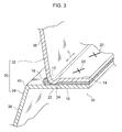
Fig. 3 is a drawing of a second modified example of an adhesion flange structure according to an exemplary embodiment of the present invention. -
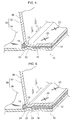
Fig. 4 is a drawing of a third modified example of an adhesion flange structure according to an exemplary embodiment of the present invention. -
Fig. 5 is a drawing of a fourth modified example of an adhesion flange structure according to an exemplary embodiment of the present invention. -
Fig. 6 is a drawing of an adhesion flange structure according to a first Comparative Example. -
Fig. 7 is a drawing of an adhesion flange structure according to a second Comparative Example. - Explanation follows regarding an exemplary embodiment of the present invention.
- A
vehicle framework member 30 illustrated inFig. 1 configures a portion of a vehicle body, and includes a firstvehicle body panel 32 and a secondvehicle body panel 34. The firstvehicle body panel 32 and the secondvehicle body panel 34 are respectively configured by steel plates. The firstvehicle body panel 32 is formed with a hat shaped cross-section profile open towards a secondvehicle body panel 34 side. The secondvehicle body panel 34 is formed in a flat plate shape, and forms a closed cross-section portion together with the firstvehicle body panel 32. Anadhesion flange structure 10 according to an exemplary embodiment of the present invention is applied to the firstvehicle body panel 32 and the secondvehicle body panel 34. - Namely, the first
vehicle body panel 32 is formed with aside wall portion 36 that projects up with respect to the secondvehicle body panel 34. An end portion at a secondvehicle body panel 34 side of theside wall portion 36 is formed with afirst flange 14 with abend portion 12 interposed therebetween. Thefirst flange 14 extends in an L direction along the end portion at the secondvehicle body panel 34 side of theside wall portion 36. An end portion at afirst flange 14 side of the secondvehicle body panel 34 is formed with asecond flange 16 facing thebend portion 12 and thefirst flange 14. - The
bend portion 12 and thefirst flange 14 are adhered to thesecond flange 16 at substantially the entire region of thebend portion 12 and thefirst flange 14 using anadhesive 18. Thefirst flange 14 and thesecond flange 16 are moreover joined together by spot welding atplural welding portions 20. Theplural welding portions 20 extend in a row at intervals to each other along the extension direction of thefirst flange 14 along the end portion at the secondvehicle body panel 34 side of theside wall portion 36, namely along the L direction. - The
bend portion 12 described above is formed with aridge projection portion 24 that projects towards a facingportion 22 side of thesecond flange 16 that faces thebend portion 12. Theridge projection portion 24 extends along the L direction described above. - Explanation follows regarding operation and advantageous effects of the exemplary embodiment of the present invention.
- In order to clarify the operation and advantageous effects of the exemplary embodiment of the present invention, explanation is first given regarding Comparative Examples. Note that for ease of comparison, configuration elements that have the same names in the Comparative Examples as in the exemplary embodiment of the present invention are allocated the same reference numerals.
- In
adhesion flange structures Fig. 6 and Fig. 7 , theridge projection portion 24 of theadhesion flange structure 10 according to the exemplary embodiment described above is omitted. - In the
adhesion flange structure 50 of a first Comparative Example illustrated inFig. 6 , thefirst flange 14 is however bent towards asecond flange 16 side due to contact by a spot gun during spot welding. - Moreover, in the
adhesion flange structure 60 of a second Comparative Example illustrated inFig. 7 , curves are put into thefirst flange 14 at plural locations during a manufacturing process. - However, when the
first flange 14 is bent towards thesecond flange 16 side as in theadhesion flange structure 50 of the first Comparative Example illustrated inFig. 6 , thebend portion 12 is adhered to thesecond flange 16 in a floating state positioned a specific dimension or greater from thesecond flange 16. The thickness of theadhesive 18 between thebend portion 12 and the facingportion 22 accordingly increases, and the rigidity of thebend portion 12 cannot be secured. - When the
first flange 14 is curved at plural locations as in theadhesion flange structure 60 of the second Comparative Example illustrated inFig. 7 , thebend portion 12 is adhered to thesecond flange 16 in a floating state positioned a specific dimension or greater from thesecond flange 16, and the rigidity of thebend portion 12 cannot be secured. - Since the
bend portion 12 serving as a ridge line portion in the firstvehicle body panel 32 is a location that readily affects the rigidity of thevehicle framework member 30, there is a concern that the rigidity of the overall vehicle framework member 3 may be decreased if the rigidity of thebend portion 12 is decreased. - Therefore, as illustrated in
Fig. 1 , according to theadhesion flange structure 10 of the exemplary embodiment of the present invention, thebend portion 12 is formed with theridge projection portion 24 that forms a projection towards the facingportion 22 side that is on the opposing side to thebend portion 12. The thickness of theadhesive 18 between thebend portion 12 and the facingportion 22 can accordingly be reduced due to forming theridge projection portion 24, thereby enabling the rigidity of thebend portion 12 to be secured. The rigidity of the overallvehicle framework member 30 can be increased as a result. - Due to forming the
ridge projection portion 24 at thebend portion 12 as described above, the amount by which thebend portion 12 is positioned floating away from thesecond flange 16 can be kept to within the specific dimension even when thefirst flange 14 is bent towards thesecond flange 16 side during spot welding. - Explanation follows regarding modified examples of an exemplary embodiment of the present invention.
- In the exemplary embodiment of the present invention described above, the second
vehicle body panel 34 is formed in a flat plate shape, however as illustrated inFig. 2 , the secondvehicle body panel 34 may be formed with a hat shaped cross-section open towards a firstvehicle body panel 32 side. In such cases, as illustrated inFig. 3 , abend portion 40 between thesecond flange 16 and aside wall portion 38 may be positioned further to an inside of thevehicle framework member 30 than thebend portion 12. - The
ridge projection portion 24 is formed to thebend portion 12 of the firstvehicle body panel 32, however as illustrated inFig. 4 , theridge projection portion 24 may be formed at the facingportion 22 of thesecond flange 16 that faces thebend portion 12. - Moreover, as illustrated in
Fig. 5 , theridge projection portion 24 may be formed at both thebend portion 12 and the facingportion 22. When such a configuration is employed, the thickness of the adhesive 18 between thebend portion 12 and the facingportion 22 can be reduced even further, thereby enabling the rigidity of thebend portion 12 to be secured even more. - The
adhesion flange structure 10 is applied to thevehicle framework member 30, however theadhesion flange structure 10 may be applied to a vehicle body section other than thevehicle framework member 30. - In addition to adhering the
first flange 14 and thesecond flange 16 together using the adhesive 18, thefirst flange 14 and thesecond flange 16 are also joined together by theplural welding portions 20, however thefirst flange 14 and thesecond flange 16 may be joined together using the adhesive 18 alone. - Explanation has been given above of an exemplary embodiment of the present invention, however the present invention is not limited to the above, and obviously various modifications may be implemented within a range not departing from the gist of the present invention.
Claims (2)
- An adhesion flange structure comprising:a first flange extending along an end portion of a first vehicle body panel, and formed at the end portion of the first vehicle body panel with a bend portion interposed therebetween;a second flange formed at an end portion of a second vehicle body panel that configures a section of a vehicle body together with the first vehicle body panel, the second flange formed facing the bend portion and the first flange;an adhesive that adheres the bend portion and the first flange to the second flange; anda ridge projection portion formed extending along a direction in which the first flange extends at the end portion of the first vehicle body panel, and formed to at least one portion out of the bend portion and a facing portion of the second flange that faces the bend portion, the ridge projection portion forming a projection towards the opposing side out of the bend portion and the facing portion.
- The adhesion flange structure of claim 1, wherein the ridge projection portion is formed to both the bend portion and the facing portion.
Applications Claiming Priority (1)
| Application Number | Priority Date | Filing Date | Title |
|---|---|---|---|
| PCT/JP2011/054648 WO2012117527A1 (en) | 2011-03-01 | 2011-03-01 | Adhesive flange structure |
Publications (3)
| Publication Number | Publication Date |
|---|---|
| EP2682613A1 true EP2682613A1 (en) | 2014-01-08 |
| EP2682613A4 EP2682613A4 (en) | 2014-10-08 |
| EP2682613B1 EP2682613B1 (en) | 2016-12-21 |
Family
ID=46757489
Family Applications (1)
| Application Number | Title | Priority Date | Filing Date |
|---|---|---|---|
| EP11859777.2A Not-in-force EP2682613B1 (en) | 2011-03-01 | 2011-03-01 | Adhesive flange structure |
Country Status (5)
| Country | Link |
|---|---|
| US (1) | US9169860B2 (en) |
| EP (1) | EP2682613B1 (en) |
| JP (1) | JP5614488B2 (en) |
| CN (1) | CN103403367B (en) |
| WO (1) | WO2012117527A1 (en) |
Cited By (2)
| Publication number | Priority date | Publication date | Assignee | Title |
|---|---|---|---|---|
| WO2017046494A1 (en) * | 2015-09-18 | 2017-03-23 | Peugeot Citroen Automobiles Sa | Assembly method between two elements made of sheet metal |
| FR3090425A1 (en) * | 2018-12-19 | 2020-06-26 | Psa Automobiles Sa | Set of assembled sheet metal parts showing at least one relief relief of a sealing material at their junction zone and method of assembling such an assembly |
Families Citing this family (9)
| Publication number | Priority date | Publication date | Assignee | Title |
|---|---|---|---|---|
| JP5940437B2 (en) * | 2012-11-29 | 2016-06-29 | ボルボトラックコーポレーション | Panel mounting structure |
| DE102013213109A1 (en) * | 2013-07-04 | 2015-01-22 | Ford Global Technologies, Llc | Method for the permanent connection of components or component areas as well as permanent connection |
| SG10201404701SA (en) * | 2013-09-24 | 2015-04-29 | United Technologies Corp | Welded assemblies and methods of making welded assemblies |
| JP6131917B2 (en) * | 2014-06-30 | 2017-05-24 | トヨタ自動車株式会社 | Bonding structure for vehicle panels |
| JP6109271B2 (en) * | 2015-02-06 | 2017-04-05 | 株式会社神戸製鋼所 | Junction structure and manufacturing method of junction structure |
| FR3041556B1 (en) * | 2015-09-30 | 2017-10-20 | Peugeot Citroen Automobiles Sa | ASSEMBLY OF METAL SHEET ELEMENTS INCLUDING FOLDING |
| JP6583557B2 (en) * | 2017-03-02 | 2019-10-02 | Jfeスチール株式会社 | Car body structure |
| US11060543B2 (en) | 2017-12-28 | 2021-07-13 | Honda Motor Co., Ltd. | Device and method of applying a sealant around a structural adhesive to prevent corrosion |
| DE102020103356A1 (en) * | 2020-02-11 | 2021-08-12 | Bayerische Motoren Werke Aktiengesellschaft | Component arrangement and method for producing a component arrangement |
Family Cites Families (29)
| Publication number | Priority date | Publication date | Assignee | Title |
|---|---|---|---|---|
| US3350536A (en) * | 1964-08-03 | 1967-10-31 | Ford Motor Co | Method for joining metal sheets |
| US3822464A (en) * | 1973-03-26 | 1974-07-09 | Gen Electric | Method of joining a tube to a roll forged sheet |
| JPS58182875U (en) | 1982-05-31 | 1983-12-06 | 日産自動車株式会社 | Panel fixation structure |
| JPS6291580A (en) * | 1985-10-18 | 1987-04-27 | Nissan Motor Co Ltd | Joining and sealing of panels |
| JPH01107974A (en) | 1987-10-21 | 1989-04-25 | Hitachi Ltd | Seal structure in sample shop |
| JPH01149063U (en) | 1988-04-05 | 1989-10-16 | ||
| JPH0592772A (en) | 1991-06-05 | 1993-04-16 | Toyota Motor Corp | Bond-connected structure of panel flange part of automobile |
| DE4240823C1 (en) * | 1992-12-04 | 1993-10-14 | Daimler Benz Ag | Welded connection of a sheet steel component with an aluminum sheet component and method for welding the two components together |
| US5362120A (en) * | 1993-04-05 | 1994-11-08 | Ford Motor Company | Vehicle body construction and method for inspection of adhesively secured joints therein |
| US5476210A (en) * | 1993-06-25 | 1995-12-19 | Fuji Jukogyo Kabushiki Kaisha | Structure for joining plate elements and method for joining the same |
| US5985435A (en) * | 1996-01-23 | 1999-11-16 | L & L Products, Inc. | Magnetized hot melt adhesive articles |
| US6751581B1 (en) * | 2000-05-11 | 2004-06-15 | Ford Motor Company | Method for simulating the formation of an adhesive joint |
| US7004536B2 (en) * | 2002-07-29 | 2006-02-28 | L&L Products, Inc. | Attachment system and method of forming same |
| US7115324B1 (en) * | 2003-08-29 | 2006-10-03 | Alcoa Inc. | Method of combining welding and adhesive bonding for joining metal components |
| US7007368B2 (en) * | 2003-11-19 | 2006-03-07 | Ford Global Technologies Llc | Hem construction for vehicular closure structure |
| JP2006167753A (en) | 2004-12-15 | 2006-06-29 | Fuji Heavy Ind Ltd | Manufacturing method of bonded metal plate |
| JP4638215B2 (en) | 2004-12-16 | 2011-02-23 | 富士重工業株式会社 | Metal plate joint structure |
| JP2007046646A (en) | 2005-08-08 | 2007-02-22 | Nissan Motor Co Ltd | Method of joining metal members |
| JP4223515B2 (en) * | 2006-04-10 | 2009-02-12 | 本田技研工業株式会社 | Metal plate joint structure |
| DE102006021020A1 (en) * | 2006-05-05 | 2007-11-08 | Man Nutzfahrzeuge Ag | Container in a motor vehicle |
| DE102006054470A1 (en) | 2006-11-18 | 2008-05-21 | Ford Global Technologies, LLC, Dearborn | Composite structure for vehicle body, has roof sheet and side part ending with connection sides over area of longitudinal seam in connection area, where roof sheet and side part are connected with each other by seam in connection retainer |
| JP2008296557A (en) | 2007-06-04 | 2008-12-11 | Mazda Motor Corp | Adhesive bonding member and method for manufacturing the member |
| CN101678739B (en) * | 2007-06-11 | 2013-05-29 | 旭硝子株式会社 | Frame member for window plate member, window plate member with frame member, and method for manufacturing window plate member with frame member |
| JP5125247B2 (en) * | 2007-06-20 | 2013-01-23 | マツダ株式会社 | Workpiece joining method |
| JP4460009B2 (en) * | 2008-03-12 | 2010-05-12 | 本田技研工業株式会社 | Vehicle roof structure |
| US7819452B2 (en) * | 2008-05-12 | 2010-10-26 | United States Council For Automotive Research | Automotive structural joint and method of making same |
| JP5326582B2 (en) * | 2009-01-08 | 2013-10-30 | マツダ株式会社 | Body structure using laser welding and spot welding together, and manufacturing method thereof |
| JP5240027B2 (en) | 2009-04-09 | 2013-07-17 | マツダ株式会社 | Metal plate joint structure |
| JP2010264827A (en) | 2009-05-13 | 2010-11-25 | Toyota Motor Corp | Body frame structure |
-
2011
- 2011-03-01 CN CN201180068774.2A patent/CN103403367B/en not_active Expired - Fee Related
- 2011-03-01 WO PCT/JP2011/054648 patent/WO2012117527A1/en not_active Ceased
- 2011-03-01 US US14/002,264 patent/US9169860B2/en not_active Expired - Fee Related
- 2011-03-01 JP JP2013502097A patent/JP5614488B2/en not_active Expired - Fee Related
- 2011-03-01 EP EP11859777.2A patent/EP2682613B1/en not_active Not-in-force
Cited By (3)
| Publication number | Priority date | Publication date | Assignee | Title |
|---|---|---|---|---|
| WO2017046494A1 (en) * | 2015-09-18 | 2017-03-23 | Peugeot Citroen Automobiles Sa | Assembly method between two elements made of sheet metal |
| FR3041319A1 (en) * | 2015-09-18 | 2017-03-24 | Peugeot Citroen Automobiles Sa | METHOD OF ASSEMBLY BETWEEN TWO ELEMENTS IN METALLIC SHEET |
| FR3090425A1 (en) * | 2018-12-19 | 2020-06-26 | Psa Automobiles Sa | Set of assembled sheet metal parts showing at least one relief relief of a sealing material at their junction zone and method of assembling such an assembly |
Also Published As
| Publication number | Publication date |
|---|---|
| JPWO2012117527A1 (en) | 2014-07-07 |
| US20140030010A1 (en) | 2014-01-30 |
| JP5614488B2 (en) | 2014-10-29 |
| CN103403367B (en) | 2015-03-25 |
| EP2682613B1 (en) | 2016-12-21 |
| US9169860B2 (en) | 2015-10-27 |
| WO2012117527A1 (en) | 2012-09-07 |
| CN103403367A (en) | 2013-11-20 |
| EP2682613A4 (en) | 2014-10-08 |
Similar Documents
| Publication | Publication Date | Title |
|---|---|---|
| EP2682613A1 (en) | Adhesive flange structure | |
| US11235720B2 (en) | Bumper crossmember | |
| US10457224B2 (en) | Vehicle body structure and ornamental member | |
| US10399520B2 (en) | Vehicle body structure | |
| US10843741B2 (en) | Vehicle panel structure | |
| EP3034341A1 (en) | Vehicular resin back door structure | |
| US10464511B2 (en) | Bumper reinforcement and vehicle including the same | |
| JPWO2013080965A1 (en) | Design parts arrangement structure for vehicles | |
| JP2016052855A (en) | Door sash | |
| CN103832480A (en) | Upper vehicle body rear structure | |
| JP5920134B2 (en) | Upper body structure of the vehicle | |
| JP2016141243A (en) | Vehicle body structure with weather strip | |
| US10046809B2 (en) | Body component for a motor vehicle | |
| JP6107238B2 (en) | Reinforcing member for vehicle body outer plate and vehicle door provided with the reinforcing member for vehicle body outer plate | |
| JP2013095148A (en) | Opening trim | |
| EP3059106A1 (en) | Vehicle door structure | |
| US9738325B2 (en) | Vehicle front section structure | |
| CN110386194B (en) | Structure of roof beam for vehicle | |
| JP2018168681A (en) | Roll molding light-gage steel | |
| JP2015140151A (en) | Vehicle outer plate support structure | |
| JP6253456B2 (en) | Vehicle member reinforcement structure | |
| JP2011162021A (en) | Member joining structure | |
| CN217396206U (en) | Door sealing strip and have its vehicle | |
| US20180273096A1 (en) | Vehicle frame member | |
| CN220640042U (en) | Bending piece and container side wall |
Legal Events
| Date | Code | Title | Description |
|---|---|---|---|
| PUAI | Public reference made under article 153(3) epc to a published international application that has entered the european phase |
Free format text: ORIGINAL CODE: 0009012 |
|
| 17P | Request for examination filed |
Effective date: 20130910 |
|
| AK | Designated contracting states |
Kind code of ref document: A1 Designated state(s): AL AT BE BG CH CY CZ DE DK EE ES FI FR GB GR HR HU IE IS IT LI LT LU LV MC MK MT NL NO PL PT RO RS SE SI SK SM TR |
|
| DAX | Request for extension of the european patent (deleted) | ||
| A4 | Supplementary search report drawn up and despatched |
Effective date: 20140904 |
|
| RIC1 | Information provided on ipc code assigned before grant |
Ipc: F16B 5/08 20060101ALI20140829BHEP Ipc: F16B 11/00 20060101AFI20140829BHEP Ipc: B62D 27/02 20060101ALI20140829BHEP Ipc: B23K 11/11 20060101ALI20140829BHEP |
|
| GRAP | Despatch of communication of intention to grant a patent |
Free format text: ORIGINAL CODE: EPIDOSNIGR1 |
|
| INTG | Intention to grant announced |
Effective date: 20160726 |
|
| GRAS | Grant fee paid |
Free format text: ORIGINAL CODE: EPIDOSNIGR3 |
|
| GRAA | (expected) grant |
Free format text: ORIGINAL CODE: 0009210 |
|
| AK | Designated contracting states |
Kind code of ref document: B1 Designated state(s): AL AT BE BG CH CY CZ DE DK EE ES FI FR GB GR HR HU IE IS IT LI LT LU LV MC MK MT NL NO PL PT RO RS SE SI SK SM TR |
|
| REG | Reference to a national code |
Ref country code: GB Ref legal event code: FG4D |
|
| REG | Reference to a national code |
Ref country code: CH Ref legal event code: EP |
|
| REG | Reference to a national code |
Ref country code: IE Ref legal event code: FG4D |
|
| REG | Reference to a national code |
Ref country code: AT Ref legal event code: REF Ref document number: 855770 Country of ref document: AT Kind code of ref document: T Effective date: 20170115 |
|
| REG | Reference to a national code |
Ref country code: DE Ref legal event code: R096 Ref document number: 602011033733 Country of ref document: DE |
|
| PG25 | Lapsed in a contracting state [announced via postgrant information from national office to epo] |
Ref country code: LV Free format text: LAPSE BECAUSE OF FAILURE TO SUBMIT A TRANSLATION OF THE DESCRIPTION OR TO PAY THE FEE WITHIN THE PRESCRIBED TIME-LIMIT Effective date: 20161221 |
|
| REG | Reference to a national code |
Ref country code: LT Ref legal event code: MG4D |
|
| REG | Reference to a national code |
Ref country code: NL Ref legal event code: MP Effective date: 20161221 |
|
| PG25 | Lapsed in a contracting state [announced via postgrant information from national office to epo] |
Ref country code: GR Free format text: LAPSE BECAUSE OF FAILURE TO SUBMIT A TRANSLATION OF THE DESCRIPTION OR TO PAY THE FEE WITHIN THE PRESCRIBED TIME-LIMIT Effective date: 20170322 Ref country code: LT Free format text: LAPSE BECAUSE OF FAILURE TO SUBMIT A TRANSLATION OF THE DESCRIPTION OR TO PAY THE FEE WITHIN THE PRESCRIBED TIME-LIMIT Effective date: 20161221 Ref country code: SE Free format text: LAPSE BECAUSE OF FAILURE TO SUBMIT A TRANSLATION OF THE DESCRIPTION OR TO PAY THE FEE WITHIN THE PRESCRIBED TIME-LIMIT Effective date: 20161221 Ref country code: NO Free format text: LAPSE BECAUSE OF FAILURE TO SUBMIT A TRANSLATION OF THE DESCRIPTION OR TO PAY THE FEE WITHIN THE PRESCRIBED TIME-LIMIT Effective date: 20170321 |
|
| REG | Reference to a national code |
Ref country code: AT Ref legal event code: MK05 Ref document number: 855770 Country of ref document: AT Kind code of ref document: T Effective date: 20161221 |
|
| PG25 | Lapsed in a contracting state [announced via postgrant information from national office to epo] |
Ref country code: RS Free format text: LAPSE BECAUSE OF FAILURE TO SUBMIT A TRANSLATION OF THE DESCRIPTION OR TO PAY THE FEE WITHIN THE PRESCRIBED TIME-LIMIT Effective date: 20161221 Ref country code: FI Free format text: LAPSE BECAUSE OF FAILURE TO SUBMIT A TRANSLATION OF THE DESCRIPTION OR TO PAY THE FEE WITHIN THE PRESCRIBED TIME-LIMIT Effective date: 20161221 Ref country code: HR Free format text: LAPSE BECAUSE OF FAILURE TO SUBMIT A TRANSLATION OF THE DESCRIPTION OR TO PAY THE FEE WITHIN THE PRESCRIBED TIME-LIMIT Effective date: 20161221 |
|
| PG25 | Lapsed in a contracting state [announced via postgrant information from national office to epo] |
Ref country code: NL Free format text: LAPSE BECAUSE OF FAILURE TO SUBMIT A TRANSLATION OF THE DESCRIPTION OR TO PAY THE FEE WITHIN THE PRESCRIBED TIME-LIMIT Effective date: 20161221 |
|
| PG25 | Lapsed in a contracting state [announced via postgrant information from national office to epo] |
Ref country code: SK Free format text: LAPSE BECAUSE OF FAILURE TO SUBMIT A TRANSLATION OF THE DESCRIPTION OR TO PAY THE FEE WITHIN THE PRESCRIBED TIME-LIMIT Effective date: 20161221 Ref country code: CZ Free format text: LAPSE BECAUSE OF FAILURE TO SUBMIT A TRANSLATION OF THE DESCRIPTION OR TO PAY THE FEE WITHIN THE PRESCRIBED TIME-LIMIT Effective date: 20161221 Ref country code: IS Free format text: LAPSE BECAUSE OF FAILURE TO SUBMIT A TRANSLATION OF THE DESCRIPTION OR TO PAY THE FEE WITHIN THE PRESCRIBED TIME-LIMIT Effective date: 20170421 Ref country code: RO Free format text: LAPSE BECAUSE OF FAILURE TO SUBMIT A TRANSLATION OF THE DESCRIPTION OR TO PAY THE FEE WITHIN THE PRESCRIBED TIME-LIMIT Effective date: 20161221 Ref country code: EE Free format text: LAPSE BECAUSE OF FAILURE TO SUBMIT A TRANSLATION OF THE DESCRIPTION OR TO PAY THE FEE WITHIN THE PRESCRIBED TIME-LIMIT Effective date: 20161221 |
|
| PG25 | Lapsed in a contracting state [announced via postgrant information from national office to epo] |
Ref country code: BE Free format text: LAPSE BECAUSE OF FAILURE TO SUBMIT A TRANSLATION OF THE DESCRIPTION OR TO PAY THE FEE WITHIN THE PRESCRIBED TIME-LIMIT Effective date: 20161221 Ref country code: IT Free format text: LAPSE BECAUSE OF FAILURE TO SUBMIT A TRANSLATION OF THE DESCRIPTION OR TO PAY THE FEE WITHIN THE PRESCRIBED TIME-LIMIT Effective date: 20161221 Ref country code: PT Free format text: LAPSE BECAUSE OF FAILURE TO SUBMIT A TRANSLATION OF THE DESCRIPTION OR TO PAY THE FEE WITHIN THE PRESCRIBED TIME-LIMIT Effective date: 20170421 Ref country code: PL Free format text: LAPSE BECAUSE OF FAILURE TO SUBMIT A TRANSLATION OF THE DESCRIPTION OR TO PAY THE FEE WITHIN THE PRESCRIBED TIME-LIMIT Effective date: 20161221 Ref country code: AT Free format text: LAPSE BECAUSE OF FAILURE TO SUBMIT A TRANSLATION OF THE DESCRIPTION OR TO PAY THE FEE WITHIN THE PRESCRIBED TIME-LIMIT Effective date: 20161221 Ref country code: ES Free format text: LAPSE BECAUSE OF FAILURE TO SUBMIT A TRANSLATION OF THE DESCRIPTION OR TO PAY THE FEE WITHIN THE PRESCRIBED TIME-LIMIT Effective date: 20161221 Ref country code: SM Free format text: LAPSE BECAUSE OF FAILURE TO SUBMIT A TRANSLATION OF THE DESCRIPTION OR TO PAY THE FEE WITHIN THE PRESCRIBED TIME-LIMIT Effective date: 20161221 Ref country code: BG Free format text: LAPSE BECAUSE OF FAILURE TO SUBMIT A TRANSLATION OF THE DESCRIPTION OR TO PAY THE FEE WITHIN THE PRESCRIBED TIME-LIMIT Effective date: 20170321 |
|
| REG | Reference to a national code |
Ref country code: DE Ref legal event code: R097 Ref document number: 602011033733 Country of ref document: DE |
|
| PLBE | No opposition filed within time limit |
Free format text: ORIGINAL CODE: 0009261 |
|
| STAA | Information on the status of an ep patent application or granted ep patent |
Free format text: STATUS: NO OPPOSITION FILED WITHIN TIME LIMIT |
|
| REG | Reference to a national code |
Ref country code: CH Ref legal event code: PL |
|
| 26N | No opposition filed |
Effective date: 20170922 |
|
| GBPC | Gb: european patent ceased through non-payment of renewal fee |
Effective date: 20170321 |
|
| PG25 | Lapsed in a contracting state [announced via postgrant information from national office to epo] |
Ref country code: DK Free format text: LAPSE BECAUSE OF FAILURE TO SUBMIT A TRANSLATION OF THE DESCRIPTION OR TO PAY THE FEE WITHIN THE PRESCRIBED TIME-LIMIT Effective date: 20161221 Ref country code: MC Free format text: LAPSE BECAUSE OF FAILURE TO SUBMIT A TRANSLATION OF THE DESCRIPTION OR TO PAY THE FEE WITHIN THE PRESCRIBED TIME-LIMIT Effective date: 20161221 |
|
| REG | Reference to a national code |
Ref country code: DE Ref legal event code: R084 Ref document number: 602011033733 Country of ref document: DE |
|
| REG | Reference to a national code |
Ref country code: IE Ref legal event code: MM4A |
|
| REG | Reference to a national code |
Ref country code: FR Ref legal event code: ST Effective date: 20171130 |
|
| PG25 | Lapsed in a contracting state [announced via postgrant information from national office to epo] |
Ref country code: FR Free format text: LAPSE BECAUSE OF NON-PAYMENT OF DUE FEES Effective date: 20170331 Ref country code: LU Free format text: LAPSE BECAUSE OF NON-PAYMENT OF DUE FEES Effective date: 20170301 |
|
| PG25 | Lapsed in a contracting state [announced via postgrant information from national office to epo] |
Ref country code: LI Free format text: LAPSE BECAUSE OF NON-PAYMENT OF DUE FEES Effective date: 20170331 Ref country code: CH Free format text: LAPSE BECAUSE OF NON-PAYMENT OF DUE FEES Effective date: 20170331 Ref country code: SI Free format text: LAPSE BECAUSE OF FAILURE TO SUBMIT A TRANSLATION OF THE DESCRIPTION OR TO PAY THE FEE WITHIN THE PRESCRIBED TIME-LIMIT Effective date: 20161221 Ref country code: GB Free format text: LAPSE BECAUSE OF NON-PAYMENT OF DUE FEES Effective date: 20170321 Ref country code: IE Free format text: LAPSE BECAUSE OF NON-PAYMENT OF DUE FEES Effective date: 20170301 |
|
| PG25 | Lapsed in a contracting state [announced via postgrant information from national office to epo] |
Ref country code: MT Free format text: LAPSE BECAUSE OF NON-PAYMENT OF DUE FEES Effective date: 20170301 |
|
| PG25 | Lapsed in a contracting state [announced via postgrant information from national office to epo] |
Ref country code: HU Free format text: LAPSE BECAUSE OF FAILURE TO SUBMIT A TRANSLATION OF THE DESCRIPTION OR TO PAY THE FEE WITHIN THE PRESCRIBED TIME-LIMIT; INVALID AB INITIO Effective date: 20110301 |
|
| PG25 | Lapsed in a contracting state [announced via postgrant information from national office to epo] |
Ref country code: CY Free format text: LAPSE BECAUSE OF NON-PAYMENT OF DUE FEES Effective date: 20161221 |
|
| PG25 | Lapsed in a contracting state [announced via postgrant information from national office to epo] |
Ref country code: MK Free format text: LAPSE BECAUSE OF FAILURE TO SUBMIT A TRANSLATION OF THE DESCRIPTION OR TO PAY THE FEE WITHIN THE PRESCRIBED TIME-LIMIT Effective date: 20161221 |
|
| PG25 | Lapsed in a contracting state [announced via postgrant information from national office to epo] |
Ref country code: TR Free format text: LAPSE BECAUSE OF FAILURE TO SUBMIT A TRANSLATION OF THE DESCRIPTION OR TO PAY THE FEE WITHIN THE PRESCRIBED TIME-LIMIT Effective date: 20161221 |
|
| PG25 | Lapsed in a contracting state [announced via postgrant information from national office to epo] |
Ref country code: AL Free format text: LAPSE BECAUSE OF FAILURE TO SUBMIT A TRANSLATION OF THE DESCRIPTION OR TO PAY THE FEE WITHIN THE PRESCRIBED TIME-LIMIT Effective date: 20161221 |
|
| PGFP | Annual fee paid to national office [announced via postgrant information from national office to epo] |
Ref country code: DE Payment date: 20210216 Year of fee payment: 11 |
|
| REG | Reference to a national code |
Ref country code: DE Ref legal event code: R119 Ref document number: 602011033733 Country of ref document: DE |
|
| PG25 | Lapsed in a contracting state [announced via postgrant information from national office to epo] |
Ref country code: DE Free format text: LAPSE BECAUSE OF NON-PAYMENT OF DUE FEES Effective date: 20221001 |