JP5940437B2 - Panel mounting structure - Google Patents
Panel mounting structure Download PDFInfo
- Publication number
- JP5940437B2 JP5940437B2 JP2012261141A JP2012261141A JP5940437B2 JP 5940437 B2 JP5940437 B2 JP 5940437B2 JP 2012261141 A JP2012261141 A JP 2012261141A JP 2012261141 A JP2012261141 A JP 2012261141A JP 5940437 B2 JP5940437 B2 JP 5940437B2
- Authority
- JP
- Japan
- Prior art keywords
- panel
- sheet metal
- metal panel
- inclined surface
- peripheral edge
- Prior art date
- Legal status (The legal status is an assumption and is not a legal conclusion. Google has not performed a legal analysis and makes no representation as to the accuracy of the status listed.)
- Expired - Fee Related
Links
- 230000002093 peripheral effect Effects 0.000 claims description 39
- 239000011521 glass Substances 0.000 claims description 36
- 239000000853 adhesive Substances 0.000 claims description 27
- 230000001070 adhesive effect Effects 0.000 claims description 27
- 238000007789 sealing Methods 0.000 claims description 8
- 239000002184 metal Substances 0.000 description 56
- 239000005357 flat glass Substances 0.000 description 5
- 238000003466 welding Methods 0.000 description 5
- 239000003973 paint Substances 0.000 description 4
- 238000013459 approach Methods 0.000 description 3
- XLYOFNOQVPJJNP-UHFFFAOYSA-N water Substances O XLYOFNOQVPJJNP-UHFFFAOYSA-N 0.000 description 2
- 101100494448 Caenorhabditis elegans cab-1 gene Proteins 0.000 description 1
- 230000004048 modification Effects 0.000 description 1
- 238000012986 modification Methods 0.000 description 1
- 230000000717 retained effect Effects 0.000 description 1
- 238000009420 retrofitting Methods 0.000 description 1
Images


Classifications
-
- B—PERFORMING OPERATIONS; TRANSPORTING
- B62—LAND VEHICLES FOR TRAVELLING OTHERWISE THAN ON RAILS
- B62D—MOTOR VEHICLES; TRAILERS
- B62D33/00—Superstructures for load-carrying vehicles
- B62D33/06—Drivers' cabs
-
- B—PERFORMING OPERATIONS; TRANSPORTING
- B62—LAND VEHICLES FOR TRAVELLING OTHERWISE THAN ON RAILS
- B62D—MOTOR VEHICLES; TRAILERS
- B62D27/00—Connections between superstructure or understructure sub-units
- B62D27/02—Connections between superstructure or understructure sub-units rigid
- B62D27/026—Connections by glue bonding
Description
本発明はパネル取付構造に係り、詳しくはトラックのキャブに設けたガラス取付用開口部への板金パネルの取付構造に関する。 The present invention relates to a panel mounting structure, and more particularly to a mounting structure of a sheet metal panel to a glass mounting opening provided in a cab of a truck.
図7に示すように、従来、トラックのキャブ1には、リア側のパネル(バックパネル)3にガラス取付用開口部5が形成され、ガラス取付用開口部5にウェザーストリップ7を用いてウインドガラス9が取り付けられている。そして、特許文献1をはじめ、従来、この種のウインドガラスの取付構造に関し様々な提案がなされている。 As shown in FIG. 7, conventionally, a truck cab 1 has a glass attachment opening 5 formed in a rear panel (back panel) 3, and a weatherstrip 7 is used for the glass attachment opening 5. Glass 9 is attached. Various proposals have been made regarding a wind glass mounting structure of this type, including Patent Document 1.
一方、箱型荷台を搭載した大型トラック等、仕様に応じリアのウインドガラスが不要になる車両が存在する。このような車両の場合、ウインドガラスに代え、ガラス取付用開口部に板金パネルをウェザーストリップ(ラバーシール)や接着剤を用いて後付けしている。 On the other hand, there are vehicles such as a large truck equipped with a box-type loading platform that do not require a rear window glass depending on specifications. In the case of such a vehicle, a sheet metal panel is retrofitted by using a weather strip (rubber seal) or an adhesive instead of the window glass.
ところで、前記ガラス取付用開口部は、キャブの溶接メインラインで溶接ロボットアームの作業孔として使用され、また、スポットガンの作業孔として使用されている。 By the way, the glass mounting opening is used as a work hole for the welding robot arm in the welding main line of the cab, and is also used as a work hole for the spot gun.
このため、ガラス取付用開口部を予め板金パネルで塞いでしまうとスポット溶接が不可能となり、また、仮にスポット溶接が可能であっても、ロボットアーム側の大掛かりな改造が必要となる。 For this reason, if the glass mounting opening is previously closed with a sheet metal panel, spot welding becomes impossible, and even if spot welding is possible, a major modification on the robot arm side is required.
そこで、キャブの全てのスポット溶接後に、板金パネルをガラス取付用開口部に後付けして前記課題を解決している。 Therefore, after all spot welding of the cab, the sheet metal panel is retrofitted to the glass mounting opening to solve the above problem.
しかし、ガラス取付用開口部への板金パネルの後付けは、人の手作業で行われている。このため、ガラス取付用開口部への板金パネルの組付け作業性や組付け精度に課題があり、また、板金パネル自体でガラス取付用開口部を塞ぐ構造ではないため、水密性確保のためのシーリングが必要となり、高い組立精度が望まれている。 However, the retrofitting of the sheet metal panel to the glass mounting opening is performed manually. For this reason, there is a problem in the workability and accuracy of assembling the sheet metal panel to the glass mounting opening, and because the sheet metal panel itself does not have a structure for closing the glass mounting opening, Sealing is required, and high assembly accuracy is desired.
また、例えば接着剤を用いて板金パネルをガラス取付用開口部に取り付けた際に、接着剤が板金パネルの表面等に流れ出てしまうことがあるが、このような場合、接着剤の後処理に手間がかかる欠点も指摘されていた。 Also, for example, when the sheet metal panel is attached to the glass mounting opening using an adhesive, the adhesive may flow out to the surface of the sheet metal panel. It also pointed out the time-consuming drawbacks.
本発明は斯かる実情に鑑み案出されたもので、キャブのガラス取付用開口部に板金パネルを取り付けるに当たり、板金パネルの組付け性,組付精度の向上を図ったパネル取付構造を提供することを目的とする。 The present invention has been devised in view of such circumstances, and provides a panel mounting structure that improves the assembling property and the assembling accuracy of the sheet metal panel when mounting the sheet metal panel to the glass mounting opening of the cab. For the purpose.
斯かる目的を達成するため、本発明は、キャブのリア側のガラス取付用開口部に、ガラス取付用開口部を塞ぐパネルを取り付けたパネル取付構造であって、キャブのガラス取付用開口部の周縁には、ガラス取付用開口部を囲繞する第1面と、第1面と接続されリア側に向けて拡径したテーパ形状をなす第2面とを有する環状の段差部が形成され、パネルは、第1面とは面接触し、外周方向に向かうに従って第2面との距離が順次幅狭となる環状の傾斜面が形成されるように外周部が折り曲げられて段差部と接着され、段差部の第1面および第2面の接続部分と、パネルの傾斜面との間隙に接着剤溜まりが形成され、段差部の第2面とパネルの傾斜面の外周側先端部とがシーリングにより密着されていることを特徴とする。 In order to achieve such an object, the present invention provides a panel mounting structure in which a panel that closes the glass mounting opening is attached to the glass mounting opening on the rear side of the cab, and the glass mounting opening of the cab is provided. An annular step portion having a first surface surrounding the glass mounting opening and a second surface having a tapered shape connected to the first surface and having a diameter increased toward the rear side is formed on the periphery, and the panel Is in surface contact with the first surface, and the outer peripheral portion is bent and bonded to the stepped portion so as to form an annular inclined surface in which the distance from the second surface is gradually narrowed toward the outer peripheral direction, An adhesive pool is formed in the gap between the connection portion of the first and second surfaces of the step portion and the inclined surface of the panel, and the second surface of the step portion and the outer peripheral end of the inclined surface of the panel are sealed. It is characterized by being in close contact .
本発明によれば、板金パネルをキャブに取り付けるに当たり、板金パネルの周縁の先端が全周に亘って傾斜面に接近するように周縁を傾斜させているので、傾斜面に対する板金パネルの位置決めがし易くなり、良好に取付ブラケットとの位置合わせが可能となって、容易に板金パネルを取付ブラケットに仮保持することができる。 According to the present invention, when the sheet metal panel is attached to the cab, the periphery of the sheet metal panel is inclined so that the tip of the periphery of the sheet metal panel approaches the inclined surface over the entire circumference, so that the sheet metal panel is positioned with respect to the inclined surface. It becomes easy and can be satisfactorily aligned with the mounting bracket, and the sheet metal panel can be easily temporarily held on the mounting bracket.
また、板金パネルの周縁を傾斜面方向へ延設して接着剤溜まりを形成しているため、接着剤溜まりから接着剤が外部に流れ出ることがなく、外部に流れ出た接着剤の後処理といった課題が解消される。 Also, since the adhesive pool is formed by extending the peripheral edge of the sheet metal panel in the direction of the inclined surface, the adhesive does not flow out of the adhesive pool, and the post-treatment of the adhesive that flows out Is resolved.
更にまた、板金パネルを接着剤で接着した後、板金パネルの周縁を傾斜面方向へ変形し、先端を傾斜面に密着させてシーリングしたので、板金パネルとパネルとの間の確実な水密性が確保できる。 Furthermore, after bonding the sheet metal panel with an adhesive, the periphery of the sheet metal panel is deformed in the direction of the inclined surface, and the tip is brought into close contact with the inclined surface and sealed, so that reliable water tightness between the sheet metal panel and the panel is ensured. It can be secured.
而も、板金パネルの周縁と傾斜面との間の間隙に多少のバラツキが生じていても、斯様に周縁を傾斜面へ変形,密着させることで、周縁の寸法誤差のバラツキを吸収することができる。 Even if there is some variation in the gap between the peripheral edge of the sheet metal panel and the inclined surface, the peripheral edge is deformed and brought into close contact with the inclined surface to absorb the variation in the dimensional error of the peripheral edge. Can do.
そして、ガラス取付用開口部の従来構造に何ら変更を加えていないため、取付ブラケットを省略することで、ガラス取付用開口部へのウインドガラスの取付けが可能である。 And since no change is made to the conventional structure of the opening for glass attachment, it is possible to attach the window glass to the opening for glass attachment by omitting the attachment bracket.
以下、本発明の実施形態を図面に基づいて詳細に説明する。 Hereinafter, embodiments of the present invention will be described in detail with reference to the drawings.
図1において、11はキャブオーバー型トラックのキャブを示し、キャブ11のリア側のパネル(バックパネル)13に図2の如くガラス取付用開口部15が設けられている。そして、図1,図4に示すように、ガラス取付用開口部15を覆って一枚の板金パネル17がリア側のパネル13に取り付けられている。
In FIG. 1, reference numeral 11 denotes a cab of a cab over type truck, and a
図2に示すようにパネル13への板金パネル17の取付けに当たり、ガラス取付用開口部15の周縁部19に、図3に示す取付ブラケット21が上下4箇所の所定位置に溶接される。
As shown in FIG. 2, when the
取付ブラケット21は、左右に平坦な取付フランジ23を有する断面コ字状に形成され、左右の取付フランジ23が周縁部19に溶接されて取付ブラケット21が周縁部19に固着される。そして、取付ブラケット21の頂部25の中央にボルト孔27が設けられており、この4個の取付ブラケット21に、1枚の板金パネル17がガラス取付用開口部15を覆うようにボルト29で仮保持される。
The
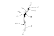
図5に示すようにリア側のパネル13には、ガラス取付用開口部15との間に僅かな距離をおいて、キャブ11の後方(図中、矢印方向)へ突出する傾斜面31がガラス取付用開口部15の全周に亘って設けられている。
As shown in FIG. 5, the
一方、板金パネル17の周縁33は傾斜面31に沿って折曲されるとともに、傾斜面31との間の間隙が先端35へと順次幅狭となるように、周縁33が傾斜面31方向へ長尺に延設されている。そして、既述したように板金パネル17を取付ブラケット21に仮保持したとき、板金パネル17は周縁33を除いてリア側のパネル13に当接し、この結果、図5に示すように板金パネル17の周縁33とパネル13との間にクリアランスが形成されて、このクリアランスが接着剤溜まり37として機能するようになっている。接着剤溜まり37には、取付ブラケット21への板金パネル17の仮保持後、接着剤39が注入,充填される。
On the other hand, the
また、斯様に板金パネル17の周縁33を、傾斜面31との間の間隙が先端35へと順次幅狭となるように傾斜面31方向へ延設した結果、板金パネル17を取付ブラケット21に仮保持したとき、一例として接着剤溜まり37の傾斜面31と周縁33との間隙Aが2mm程度であるのに対し、周縁33の先端35と傾斜面31との間隙Bはより幅狭な略1ミリとなっている。
Also, as a result of extending the
そして、板金パネル17を取付ブラケット21に仮保持した後、接着剤39に熱をかけて板金パネル17の周縁33をリア側のパネル13の周辺(傾斜面31)に接着し、周縁33を傾斜面31方向へ変形させて先端35を傾斜面31に密着させて、図6の如く周縁33の先端35と傾斜面31との間をペイントシーリング41することで、板金パネル17とパネル13との間の水密性が確保されるようになっている。
After the
本実施形態はこのように構成されているから、キャブ11への板金パネル17の取付けに当たり、図2に示すように、先ず、ガラス取付用開口部15の周縁部19に4個の取付ブラケット21を上下4箇所の所定位置に溶接する。
Since the present embodiment is configured as described above, when attaching the
この後、作業者は板金パネル17を取付ブラケット21にボルト締めするが、既述したように板金パネル17の周縁33を傾斜面31方向へ傾斜させているため、板金パネル17をガラス取付用開口部15に近づけると、板金パネル17の周縁33の先端35が全周に亘って傾斜面31に接近する。このため、傾斜面31に対する板金パネル17の位置決めがし易く、良好に取付ブラケット21との位置合わせができ、容易に板金パネル17を取付ブラケット21にボルト締めして仮保持することができることとなる。
Thereafter, the operator bolts the
そして、板金パネル17の仮保持後、接着剤溜まり37に接着剤39を注入,充填して接着剤39に熱をかければ、板金パネル17の周縁33が傾斜面31に接着して板金パネル17がキャブ11に取り付くが、板金パネル1の周縁33を傾斜面31方向へ長尺に延設しているため、接着剤溜まり37から接着剤39が外部に流れ出ることがない。
Then, after temporarily holding the
この後、周縁33を傾斜面31方向へ変形させて先端35を傾斜面31に密着させ、図6の如く周縁33の先端35と傾斜面31との間をペイントシーリング41すれば、板金パネル17とパネル13との間の水密性が確保されることとなる。
Thereafter, the
このように、本実施形態は、
(a)板金パネル17をキャブ11に取り付けるに当たり、板金パネル17の周縁33の先端35が全周に亘って傾斜面31に接近するように周縁33を傾斜させているので、傾斜面31に対する板金パネル17の位置決めがし易くなり、良好に取付ブラケット21との位置合わせが可能となって、容易に板金パネル17を取付ブラケット21に仮保持することができる利点を有する。
Thus, this embodiment is
(a) When attaching the
(b)板金パネル17の周縁33を傾斜面31方向へ長尺に延設して接着剤溜まり37を形成しているため、接着剤溜まり37から接着剤39が外部に流れ出ることがなく、外部に流れ出た接着剤の後処理といった課題が解消される。
(b) Since the
(c)板金パネル17を接着剤39で接着した後、板金パネル37の周縁33を傾斜面31方向へ変形し、先端35を傾斜面31に密着させてペイントシーリング41ができるので、板金パネル17とパネル13との間の確実な水密性が確保できることとなる。
(c) Since the
しかも、板金パネル17の周縁33と傾斜面31との間の間隙に多少のバラツキが生じていても、斯様に周縁33を傾斜面31へ変形,密着させることで、周縁33の寸法誤差のバラツキを吸収することができる。
Moreover, even if there is some variation in the gap between the
(d)また、ガラス取付用開口部15の従来構造に何ら変更を加えていないため、取付ブラケット21を省略することで、ガラス取付用開口部15へのウインドガラスの取付けが可能である。
(d) Since the conventional structure of the glass attachment opening 15 is not changed, the window glass can be attached to the glass attachment opening 15 by omitting the
11・・・キャブ、13・・・リア側のパネル(バックパネル)、15・・・ガラス取付用開口部、17・・・板金パネル、19・・・ガラス取付用開口部の周縁部、21・・・取付ブラケット、31・・・傾斜面、33・・・板金パネルの周縁、35・・・板金パネルの周縁の先端、37・・・接着剤溜まり、39・・・接着剤、41・・・ペイントシーリング
DESCRIPTION OF SYMBOLS 11 ... Cab, 13 ... Panel on the rear side (back panel), 15 ... Glass mounting opening, 17 ... Sheet metal panel, 19 ... Perimeter of glass mounting opening, 21・ ・ ・ Mounting bracket, 31 ... Inclined surface, 33 ... Periphery of sheet metal panel, 35 ... Tip of peripheral edge of sheet metal panel, 37 ... Adhesive reservoir, 39 ... Adhesive, 41 ..Paint sealing
Claims (1)
前記キャブの前記ガラス取付用開口部の周縁には、前記ガラス取付用開口部を囲繞する第1面と、前記第1面と接続され前記リア側に向けて拡径したテーパ形状をなす第2面とを有する環状の段差部が形成され、The peripheral edge of the glass mounting opening of the cab has a first surface that surrounds the glass mounting opening, and a second taper that is connected to the first surface and has a diameter increased toward the rear side. An annular step having a surface is formed,
前記パネルは、前記第1面とは面接触し、外周方向に向かうに従って前記第2面との距離が順次幅狭となる環状の傾斜面が形成されるように外周部が折り曲げられて前記段差部と接着され、The panel is brought into surface contact with the first surface, and an outer peripheral portion is bent so that an annular inclined surface is formed in which the distance from the second surface is gradually narrowed toward the outer peripheral direction. Glued to the part,
前記段差部の前記第1面および前記第2面の接続部分と、前記パネルの傾斜面との間隙に接着剤溜まりが形成され、An adhesive pool is formed in a gap between the connection portion of the first surface and the second surface of the stepped portion and the inclined surface of the panel;
前記段差部の前記第2面と前記パネルの傾斜面の外周側先端部とがシーリングにより密着されているThe second surface of the stepped portion and the outer peripheral end of the inclined surface of the panel are in close contact by sealing.
ことを特徴とするパネル取付構造。A panel mounting structure characterized by that.
Priority Applications (5)
| Application Number | Priority Date | Filing Date | Title |
|---|---|---|---|
| JP2012261141A JP5940437B2 (en) | 2012-11-29 | 2012-11-29 | Panel mounting structure |
| US14/647,969 US9403561B2 (en) | 2012-11-29 | 2013-05-29 | Mounting structure of sheet metal panel |
| CN201380062516.2A CN104884338B (en) | 2012-11-29 | 2013-05-29 | The installation method of sheet metal panel |
| PCT/JP2013/003389 WO2014083719A1 (en) | 2012-11-29 | 2013-05-29 | Sheet-metal panel mounting structure |
| EP13858681.3A EP2927099B1 (en) | 2012-11-29 | 2013-05-29 | Sheet-metal panel mounting structure |
Applications Claiming Priority (1)
| Application Number | Priority Date | Filing Date | Title |
|---|---|---|---|
| JP2012261141A JP5940437B2 (en) | 2012-11-29 | 2012-11-29 | Panel mounting structure |
Publications (2)
| Publication Number | Publication Date |
|---|---|
| JP2014104930A JP2014104930A (en) | 2014-06-09 |
| JP5940437B2 true JP5940437B2 (en) | 2016-06-29 |
Family
ID=50827386
Family Applications (1)
| Application Number | Title | Priority Date | Filing Date |
|---|---|---|---|
| JP2012261141A Expired - Fee Related JP5940437B2 (en) | 2012-11-29 | 2012-11-29 | Panel mounting structure |
Country Status (5)
| Country | Link |
|---|---|
| US (1) | US9403561B2 (en) |
| EP (1) | EP2927099B1 (en) |
| JP (1) | JP5940437B2 (en) |
| CN (1) | CN104884338B (en) |
| WO (1) | WO2014083719A1 (en) |
Families Citing this family (4)
| Publication number | Priority date | Publication date | Assignee | Title |
|---|---|---|---|---|
| JP6117759B2 (en) * | 2014-10-06 | 2017-04-19 | 本田技研工業株式会社 | Body structure with window panel |
| CN115853053A (en) | 2017-04-19 | 2023-03-28 | 克拉克设备公司 | Loader cab |
| CN108618728A (en) * | 2018-05-07 | 2018-10-09 | 华帝股份有限公司 | Dish-washing machine display control panel and its dish-washing machine |
| FR3093063B1 (en) * | 2019-02-21 | 2021-01-22 | Psa Automobiles Sa | Subassembly of bodywork elements of a motor vehicle, comprising two concurrent sheets between which is provided a reserve for receiving a sealing member |
Family Cites Families (14)
| Publication number | Priority date | Publication date | Assignee | Title |
|---|---|---|---|---|
| DE2536820A1 (en) * | 1975-08-19 | 1977-03-03 | Kloeckner Humboldt Deutz Ag | VEHICLE CAB, ESPECIALLY FOR AGRICULTURAL AND / OR CONSTRUCTION TRACTORS |
| JPS6291580A (en) * | 1985-10-18 | 1987-04-27 | Nissan Motor Co Ltd | Joining and sealing of panels |
| JP2512823Y2 (en) * | 1989-11-15 | 1996-10-02 | 富士重工業株式会社 | Truck body structure |
| US6149228A (en) * | 1998-12-09 | 2000-11-21 | Deere & Company | Modular operator enclosure |
| JP4610704B2 (en) * | 2000-04-12 | 2011-01-12 | 富士重工業株式会社 | Adhesive water dripping prevention structure for vehicle rear gate |
| JP4924921B2 (en) * | 2006-06-28 | 2012-04-25 | いすゞ自動車株式会社 | Front panel structure |
| DE102006054470A1 (en) * | 2006-11-18 | 2008-05-21 | Ford Global Technologies, LLC, Dearborn | Composite structure for vehicle body, has roof sheet and side part ending with connection sides over area of longitudinal seam in connection area, where roof sheet and side part are connected with each other by seam in connection retainer |
| JP4464383B2 (en) * | 2006-11-27 | 2010-05-19 | いすゞ自動車株式会社 | Cab body structure |
| CN200985050Y (en) * | 2006-12-22 | 2007-12-05 | 马鹰 | Combination type medium and small wheeled type tractor steering room |
| JP2008296557A (en) * | 2007-06-04 | 2008-12-11 | Mazda Motor Corp | Adhesion joint member and manufacturing method of the member |
| WO2010007870A1 (en) * | 2008-07-16 | 2010-01-21 | 株式会社小松製作所 | Cab for construction machine |
| CN201268346Y (en) * | 2008-08-06 | 2009-07-08 | 杜成甫 | Structure assembly of driver's cab |
| JP2012086733A (en) | 2010-10-21 | 2012-05-10 | Ud Trucks Corp | Temporary holding structure for window glass |
| CN103403367B (en) * | 2011-03-01 | 2015-03-25 | 丰田自动车株式会社 | Adhesive flange structure |
-
2012
- 2012-11-29 JP JP2012261141A patent/JP5940437B2/en not_active Expired - Fee Related
-
2013
- 2013-05-29 EP EP13858681.3A patent/EP2927099B1/en not_active Not-in-force
- 2013-05-29 US US14/647,969 patent/US9403561B2/en active Active
- 2013-05-29 WO PCT/JP2013/003389 patent/WO2014083719A1/en active Application Filing
- 2013-05-29 CN CN201380062516.2A patent/CN104884338B/en active Active
Also Published As
| Publication number | Publication date |
|---|---|
| US20150298746A1 (en) | 2015-10-22 |
| CN104884338A (en) | 2015-09-02 |
| EP2927099A1 (en) | 2015-10-07 |
| WO2014083719A1 (en) | 2014-06-05 |
| JP2014104930A (en) | 2014-06-09 |
| EP2927099B1 (en) | 2018-07-04 |
| US9403561B2 (en) | 2016-08-02 |
| EP2927099A4 (en) | 2016-11-30 |
| CN104884338B (en) | 2017-03-08 |
Similar Documents
| Publication | Publication Date | Title |
|---|---|---|
| JP4273922B2 (en) | Body member joint structure | |
| JP5940437B2 (en) | Panel mounting structure | |
| US9399385B2 (en) | Rear window assembly | |
| KR20110127790A (en) | A shield structure of door welds for automobile | |
| US9610981B1 (en) | Vehicle body assembly | |
| WO2018176684A1 (en) | Matching structure of car body roof cover outer plate and sunroof reinforcing plate, car body roof cover and car | |
| CN206436823U (en) | Filler cap fixed seat sealing structure based on sealing plate | |
| CN111301535A (en) | C post threshold roof beam connection structure and car | |
| JP4322200B2 (en) | back door | |
| KR100828616B1 (en) | Structure for combination sunroof ring reinf of automobile | |
| CN205202700U (en) | Car door sealing strip | |
| CN208559224U (en) | Semitrailer and its tool box | |
| CN210591343U (en) | Mounting structure of integral type sunroof beaded finish | |
| CN211336205U (en) | Side wall and top cap connection structure and vehicle of vehicle | |
| US11124248B2 (en) | Tailgate panel assembly for a vehicle | |
| CN203186445U (en) | Automobile wheel cover | |
| CN106143311A (en) | A kind of mirror mounting structure on car door | |
| CN2915639Y (en) | Adhesion type glass locating pin structure | |
| CN203047383U (en) | Saloon car back skirt plate assembly | |
| CN207644471U (en) | Vehicle and its installing structure of top cover, head cover installation assembly | |
| CN113043814B (en) | Rear windshield additional strengthening and vehicle | |
| JP2015116869A (en) | Vehicle roof structure | |
| JP2006096113A (en) | Wheel house part structure of automobile | |
| CN204077818U (en) | One lifts tailgate formula automobile and rear cover assembly thereof | |
| CN216994530U (en) | Car A post waterproof seal structure |
Legal Events
| Date | Code | Title | Description |
|---|---|---|---|
| A521 | Request for written amendment filed |
Free format text: JAPANESE INTERMEDIATE CODE: A523 Effective date: 20150212 |
|
| A621 | Written request for application examination |
Free format text: JAPANESE INTERMEDIATE CODE: A621 Effective date: 20150225 |
|
| A131 | Notification of reasons for refusal |
Free format text: JAPANESE INTERMEDIATE CODE: A131 Effective date: 20160202 |
|
| A521 | Request for written amendment filed |
Free format text: JAPANESE INTERMEDIATE CODE: A523 Effective date: 20160415 |
|
| A521 | Request for written amendment filed |
Free format text: JAPANESE INTERMEDIATE CODE: A523 Effective date: 20160418 |
|
| TRDD | Decision of grant or rejection written | ||
| A01 | Written decision to grant a patent or to grant a registration (utility model) |
Free format text: JAPANESE INTERMEDIATE CODE: A01 Effective date: 20160517 |
|
| A61 | First payment of annual fees (during grant procedure) |
Free format text: JAPANESE INTERMEDIATE CODE: A61 Effective date: 20160518 |
|
| R150 | Certificate of patent or registration of utility model |
Ref document number: 5940437 Country of ref document: JP Free format text: JAPANESE INTERMEDIATE CODE: R150 |
|
| R250 | Receipt of annual fees |
Free format text: JAPANESE INTERMEDIATE CODE: R250 |
|
| R250 | Receipt of annual fees |
Free format text: JAPANESE INTERMEDIATE CODE: R250 |
|
| R250 | Receipt of annual fees |
Free format text: JAPANESE INTERMEDIATE CODE: R250 |
|
| S111 | Request for change of ownership or part of ownership |
Free format text: JAPANESE INTERMEDIATE CODE: R313113 |
|
| R350 | Written notification of registration of transfer |
Free format text: JAPANESE INTERMEDIATE CODE: R350 |
|
| R250 | Receipt of annual fees |
Free format text: JAPANESE INTERMEDIATE CODE: R250 |
|
| LAPS | Cancellation because of no payment of annual fees |