EP2682307A1 - Component arrangement structure for roof side rail - Google Patents
Component arrangement structure for roof side rail Download PDFInfo
- Publication number
- EP2682307A1 EP2682307A1 EP11855256.1A EP11855256A EP2682307A1 EP 2682307 A1 EP2682307 A1 EP 2682307A1 EP 11855256 A EP11855256 A EP 11855256A EP 2682307 A1 EP2682307 A1 EP 2682307A1
- Authority
- EP
- European Patent Office
- Prior art keywords
- barrier net
- side rail
- roof side
- inflator
- net anchoring
- Prior art date
- Legal status (The legal status is an assumption and is not a legal conclusion. Google has not performed a legal analysis and makes no representation as to the accuracy of the status listed.)
- Granted
Links
Images


Classifications
-
- B—PERFORMING OPERATIONS; TRANSPORTING
- B60—VEHICLES IN GENERAL
- B60R—VEHICLES, VEHICLE FITTINGS, OR VEHICLE PARTS, NOT OTHERWISE PROVIDED FOR
- B60R21/00—Arrangements or fittings on vehicles for protecting or preventing injuries to occupants or pedestrians in case of accidents or other traffic risks
- B60R21/02—Occupant safety arrangements or fittings, e.g. crash pads
- B60R21/06—Safety nets, transparent sheets, curtains, or the like, e.g. between occupants and glass
-
- B—PERFORMING OPERATIONS; TRANSPORTING
- B60—VEHICLES IN GENERAL
- B60R—VEHICLES, VEHICLE FITTINGS, OR VEHICLE PARTS, NOT OTHERWISE PROVIDED FOR
- B60R21/00—Arrangements or fittings on vehicles for protecting or preventing injuries to occupants or pedestrians in case of accidents or other traffic risks
- B60R21/02—Occupant safety arrangements or fittings, e.g. crash pads
-
- B—PERFORMING OPERATIONS; TRANSPORTING
- B60—VEHICLES IN GENERAL
- B60R—VEHICLES, VEHICLE FITTINGS, OR VEHICLE PARTS, NOT OTHERWISE PROVIDED FOR
- B60R21/00—Arrangements or fittings on vehicles for protecting or preventing injuries to occupants or pedestrians in case of accidents or other traffic risks
- B60R21/02—Occupant safety arrangements or fittings, e.g. crash pads
- B60R21/026—Rigid partitions inside vehicles, e.g. between passengers and load compartments
-
- B—PERFORMING OPERATIONS; TRANSPORTING
- B60—VEHICLES IN GENERAL
- B60R—VEHICLES, VEHICLE FITTINGS, OR VEHICLE PARTS, NOT OTHERWISE PROVIDED FOR
- B60R21/00—Arrangements or fittings on vehicles for protecting or preventing injuries to occupants or pedestrians in case of accidents or other traffic risks
- B60R21/02—Occupant safety arrangements or fittings, e.g. crash pads
- B60R21/16—Inflatable occupant restraints or confinements designed to inflate upon impact or impending impact, e.g. air bags
- B60R21/20—Arrangements for storing inflatable members in their non-use or deflated condition; Arrangement or mounting of air bag modules or components
- B60R21/213—Arrangements for storing inflatable members in their non-use or deflated condition; Arrangement or mounting of air bag modules or components in vehicle roof frames or pillars
Definitions
- the present invention relates to a component arrangement structure for arranging vehicle components at a roof side rail of a vehicle.
- JP-A Japanese Patent Application Laid-Open (JP-A) No. H9-290690 discloses a cargo net device (a barrier net device) that divides a luggage compartment at a vehicle rear portion from a cabin in which a driver and the like sits.
- a cargo net a barrier net
- the cargo net is unwound from inside a housing provided at an upper end side of a backrest (seatback) of a rear seat.
- a stay that is provided with a fixed hook portion and a hook portion are fixed to an end edge portion of the cargo net.
- An anchor portion is provided at the fixed hook portion and the hook portion, and the anchor portions are fitted into and anchored at anchoring members (anchoring brackets) provided at a roof side rail.
- anchoring brackets anchoring brackets
- JP-A No. 2009-226957 discloses a curtain airbag device that protects an occupant during a side collision or the like of a vehicle.
- This curtain airbag device is provided with a curtain airbag, which is arranged in a folded state along a roof side rail, and an inflator, which supplies gas to the interior of the curtain airbag.
- the inflator is fixed to the roof side rail between a middle pillar (center pillar) and a rear seat assist grip that is fixed to the roof side rail at the vehicle rearward side of the middle pillar.
- the barrier net anchoring bracket When the barrier net as described above is intended to set in a vehicle rearward vicinity of the front seat, that is, in order to use the barrier net in a state in which the rear seat is tilted forward and the luggage compartment is enlarged, the barrier net anchoring bracket must be set at the roof side rail between a center pillar and a rear seat assist grip.
- the folded curtain airbag and the inflator or the like are arranged at the roof side rail between the center pillar and the rear seat assist grip. Therefore, it is difficult to set the barrier net anchoring bracket to an optimum position of the roof side rail, and it is difficult to sufficiently assure luggage space.
- a subject of the present invention is to provide a roof side rail component arrangement structure that may easily assure space for arranging a curtain airbag inflator and a barrier net anchoring bracket at a roof side rail between a center pillar and a rear seat assist grip.
- a component arrangement structure at a roof side rail relating to a first aspect of the invention includes: an inflator that is disposed between a rear seat assist grip and a center pillar, that is fixed to a roof side rail, and that supplies gas into a curtain airbag, the rear seat assist grip being fixed to the roof side rail at a vehicle rearward side of the center pillar, and the curtain airbag being arranged along the roof side rail in a folded state; and a barrier net anchoring bracket that is disposed at a position that overlaps with the inflator as viewed in a vehicle width direction, that is fixed to the roof side rail, and at which an upper anchor portion is to be anchored, the upper anchor portion being provided at a barrier net that divides a vehicle cabin between front and rear.
- the curtain airbag inflator is disposed between the center pillar and the rear seat assist grip and is fixed to the roof side rail.
- the barrier net anchoring bracket is disposed at a position that overlaps with the inflator as viewed in the vehicle width direction and is fixed to the roof side rail.
- the upper anchor portion provided at the barrier net is anchored at this barrier net anchoring portion.
- the vehicle cabin is divided between front and rear by the barrier net.
- the barrier net anchoring bracket is disposed at a position that overlaps with the inflator as viewed in the vehicle width direction. Therefore, space for arrangement of the inflator and the barrier net anchoring bracket at the roof side rail between the center pillar and the rear seat assist grip may be easily assured.
- a component arrangement structure at a roof side rail relating to a second aspect of the invention is the component arrangement structure at a roof side rail according to the first aspect, in which the barrier net anchoring bracket includes a body fixing portion that is fixed to the roof side rail, and a barrier net anchoring portion that is disposed at the vehicle width direction inner side relative to the body fixing portion and at which the upper anchor portion is to be anchored, and the inflator is disposed between the body fixing portion and the barrier net anchoring portion.
- the inflator is disposed between the body fixing portion and barrier net anchoring portion that are provided at the barrier net anchoring bracket.
- the inflator is disposed within the cross section of the barrier net anchoring bracket, space for arrangement of the inflator and the barrier net anchoring bracket may be reduced.
- a component arrangement structure at a roof side rail relating to a third aspect of the invention is the component arrangement structure at a roof side rail according to the second aspect, in which the barrier net anchoring bracket forms an open cross-section shape that opens to the lower side.
- the inflator may be easily inserted between the body fixing portion and the barrier net anchoring portion from the lower side, using the opening in the barrier net anchoring bracket. Therefore, the work characteristics of assembly of the inflator to the roof side rail may be assured while the space for arrangement of the inflator and the barrier net anchoring bracket may be reduced.
- a component arrangement structure at a roof side rail relating to a fourth aspect of the invention is the component arrangement structure at a roof side rail according to the second aspect or the third aspect, in which an inclined portion that extends diagonally to the lower side and to the vehicle width direction outer side, so as to follow along an inner panel of the roof side rail, is provided at a vehicle width direction outer side end portion of a ceiling member of the vehicle cabin, and the barrier net anchoring bracket is disposed between the inclined portion and the inner panel, the body fixing portion is inclined along the inner panel, and the barrier net anchoring portion is inclined along the inclined portion.
- the body fixing portion of the barrier net anchoring bracket is inclined along the inner panel of the roof side rail. Therefore, a contact area between the inner panel and the body fixing portion may be assuredly large, and a strength of fixing of the barrier net anchoring bracket to the roof side rail may be improved.
- the barrier net anchoring portion of the barrier net anchoring bracket is inclined along the inclined portion provided at the ceiling member (roof head lining). Therefore, a contact area between the inclined portion of the ceiling member and the barrier net anchoring portion may be assuredly large, and unwanted flexing of the ceiling member ("sagging") may be suppressed.
- a component arrangement structure at a roof side rail relating to a fifth aspect of the invention is the component arrangement structure at a roof side rail according to any one of the second to fourth aspects, in which the body fixing portion is disposed at a position at which a portion thereof that is attached and fixed to the roof side rail does not overlap with the barrier net anchoring portion or the inflator as viewed in an attachment direction.
- the body fixing portion of the barrier net anchoring bracket when the body fixing portion of the barrier net anchoring bracket is attached and fixed to the roof side rail by the structure described above, interference between the barrier net anchoring portion and the inflator may be avoided. Therefore, the work characteristics of assembly of the barrier net anchoring bracket to the roof side rail may be excellent.
- a component arrangement structure at a roof side rail relating to a sixth aspect of the invention is the component arrangement structure at a roof side rail according to any one of the second to fifth aspects, in which an anchoring hole at which the upper anchor portion is to be fitted and anchored is formed in the barrier net anchoring portion, a resin cover is mounted at the barrier net anchoring portion, and the ceiling member of the vehicle cabin is sandwiched between the resin cover and the barrier net anchoring portion, the resin cover being provided with a door that is closable and openable between a closed position that covers the anchoring hole from the vehicle cabin inner side and an open position at which the anchoring hole is exposed to the vehicle cabin inner side.
- the anchoring hole in which the upper anchor portion of the barrier net is fitted and anchored is formed in the barrier net anchoring portion of the barrier net anchoring bracket, and the resin cover is mounted at the barrier net anchoring portion.
- the door that is capable of closing and opening, between the closed position that covers the anchoring hole from the vehicle cabin inner side thereof and the open position at which the anchoring hole is exposed to the vehicle cabin inner side, is provided at the resin cover. Therefore, by the door being disposed at the closed position when the barrier net is not in use, the anchoring hole may be prevented from being seen from the vehicle cabin inner side.
- the ceiling member (roof head lining) of the vehicle cabin is sandwiched between the resin cover and the barrier net anchoring portion. Therefore, unwanted flexing of the ceiling member ("sagging") may be suppressed.
- a component arrangement structure at a roof side rail relating to a seventh aspect of the invention is the component arrangement structure at a roof side rail according to any one of the second to sixth aspects, further including a protector that is disposed between the barrier net anchoring portion and the inflator, that is mounted to the barrier net anchoring portion, and that prevents the upper anchor portion from abutting against the inflator.
- a component arrangement structure at a roof side rail relating to an eighth aspect of the invention is the component arrangement structure at a roof side rail according to any one of the first to seventh aspects, in which the inflator is disposed in a state in which a length direction thereof is along the vehicle front-rear direction, and the inflator is fixed to the roof side rail via mounting brackets at both a vehicle forward side and a vehicle rearward side of the barrier net anchoring bracket.
- the inflator that is disposed with the length direction thereof along the vehicle front-rear direction is fixed to the roof side rail via the mounting brackets that are at both the vehicle forward side and the vehicle rearward side of the barrier net anchoring bracket. Therefore, the long, narrow inflator may be securely fixed to the roof side rail.
- a component arrangement structure at a roof side rail relating to a ninth aspect of the invention is the component arrangement structure at a roof side rail according to any one of the first to eighth aspects, in which the barrier net is unwindably rolled up and stowed in a housing that is provided at an upper end side of a tilting-type rear seatback that structures a rear seat, and in a state in which the rear seatback is tilted forward, the barrier net anchoring bracket is disposed above the housing as viewed in the vehicle width direction.
- the barrier net is unwindably rolled up and stowed in the housing provided at the upper end side of the rear seatback.
- the housing When the rear seatback is tilted forward, the housing is disposed at the front end side of the rear seat.
- the barrier net stowed in the housing is unwound, the upper anchor portion of the barrier net is anchored at the barrier net anchoring bracket, and the vehicle cabin is divided between front and rear at the front end side of the rear seat.
- the barrier net anchoring bracket is disposed above the housing in this state, the barrier net extends in the up-down direction or substantially in the up-down direction. Therefore, the appearance and the like of the barrier net when in use may be excellent.
- a roof side rail component arrangement structure 10 relating to an exemplary embodiment of the present invention is described using Fig. 1 to Fig. 6 .
- the arrow FR in the drawings indicates a vehicle forward side
- the arrow UP indicates the vehicle upward side
- the arrow IN indicates the inner side in the vehicle width direction.
- a vehicle 12 relating to the present exemplary embodiment is a station wagon-type automobile.
- a luggage space 18 (luggage compartment) that is continuous with a cabin space 16 is provided at the vehicle rearward side of a rear seat 14.
- the rear seat 14 is provided with a tilting-type rear seatback 20.
- the lower end side of the rear seatback 20 is joined to the vehicle body via an unillustrated hinge.
- the rear seatback 20 is tiltable between the upright position shown in Fig. 1 and the tilted forward position shown in Fig. 2 . In a state in which the rear seatback 20 is disposed at the tilted forward position, the rear seatback 20 is put over a seat cushion 22, and the luggage space 18 is enlarged as far as vicinity at the vehicle rearward side of a front seat 24.
- a housing 26 for a barrier net is provided at the rear face side of an upper end portion of the rear seatback 20 (see Fig. 3 ).
- the housing 26 is formed in a long, narrow box shape along the vehicle width direction, and is mounted to the rear face of the rear seatback 20 via a bracket 25.
- a length dimension of the housing 26 is set to substantially equal a width dimension (a dimension along the vehicle width direction) of the rear seatback 20.
- a long, thin winding spindle 27 (see Fig. 1 and Fig. 2 ) is arranged along the length direction of the housing 26.
- This winding spindle 27 is rotatably supported in the housing 26, and is urged one way about its axis by an urging unit such as a spiral spring or the like.
- a barrier net 28 is unwindably rolled up on the winding spindle 27 and stowed.
- the barrier net 28 divides the vehicle cabin into front and rear, within the cabin space 16 and the luggage space 18. Thus, the barrier net 28 is for restraining luggage in the luggage space 18 from entering the cabin space 16.
- the barrier net 28 is provided with a net main body 30 that is formed of a net-form material with flexibility.
- the net main body 30 is formed in a trapezoid shape in the deployed state thereof.
- an end portion at a bottom edge side of the net main body 30 formed in the trapezoid shape is referred to as a lower end portion and an end portion at an upper edge side of the same is referred to as an upper end portion.
- the lower end portion of the net main body 30 is anchored at the winding spindle 27.
- the net main body 30 is rolled up on the winding spindle 27, starting from the lower end side of the net main body 30, and is stowed inside the housing 26.
- the net main body 30 is unwound out of the housing 26, starting from the upper end side of the net main body 30, through a slit formed in the housing 26.
- a rod-retaining cloth 32 (not illustrated in the drawings apart from Fig. 3 ), which is formed of a sheet-form material with flexibility, is sewn to the upper end portion of the net main body 30 in a state of being folded into a substantial tube shape.
- An upper anchor rod 34 (upper anchor portions), which is formed of a rod member made of metal, is inserted inside the rod-retaining cloth 32.
- the upper anchor rod 34 is retained at the upper end portion of the net main body 30 by the rod-retaining cloth 32 in a state in which the length direction of the upper anchor rod 34 is in the vehicle width direction.
- An anchored portion 34A is provided at each of the two length direction end portions of the upper anchor rod 34 and protrudes outside of the rod-retaining cloth 32. These anchored portions 34A correspond with barrier net anchoring brackets 38 that are provided at roof side rails 36.
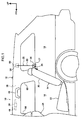
- Fig. 4 shows a side view, viewed from the vehicle cabin side, of structures peripheral to each roof side rail 36.
- Fig. 5 shows a magnified perspective view in which a portion of Fig. 4 is magnified
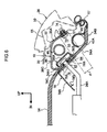
- Fig. 6 shows a magnified vertical sectional view cut along line 6-6 of Fig. 4 .
- a curtain airbag 42 and an inflator 46 which are structural members of a curtain airbag device 40, and components such as a rear seat assist grip 48 and the like are arranged at the roof side rail 36.
- the roof side rail 36 has a closed cross-section structure constituted by an outer panel 50, an inner panel 52 and a reinforcement 55.
- a roof head lining 54 that constitutes a ceiling member of the vehicle cabin is arranged at the vehicle width direction inner side of the roof side rail 36 (not shown in Fig. 4 and Fig. 5 ).
- An inclined portion 54A which extends diagonally to the lower side and to the vehicle width direction outer side, is provided at a vehicle width direction outer side end portion of the roof head lining 54.
- the inclined portion 54A is inclined so as to follow along the inner panel 52 of the roof side rail 36.
- a cavity 56 which extends along the roof side rail 36 in the vehicle front-rear direction, is formed between the inclined portion 54A and the inner panel 52.
- a horizontal portion 54B protrudes to the vehicle width direction outer side from a lower end portion of the inclined portion 54A.
- a vehicle width direction outer side end portion of the horizontal portion 54B engages with a weather strip 57, which is mounted at a lower end portion of the roof side rail 36.
- the structures peripheral to the roof side rail that are described above are the same at a right side portion and a left side portion of the vehicle body, apart from being constituted with left-right symmetry. Accordingly, in the following recitations the structures at the right side portion of the vehicle body shown in Fig. 1 , Fig. 2 , and Fig. 4 to Fig. 6 are described, and descriptions of structures at the left side portion of the vehicle body are not given.
- the rear seat assist grip 48 is fixed to the inner panel 52 of the roof side rail 36 at the vehicle rearward side relative to a center pillar 58 (a B pillar).
- the rear seat assist grip 48 is a handle for an occupant of the rear seat 14 to support their body when entering and leaving the vehicle and when the vehicle is running or the like.
- a main body portion of the rear seat assist grip 48, which is gripped by the occupant, is disposed at the vehicle cabin inner side of the roof head lining 54.
- the curtain airbag device 40 is for inflating and deploying the curtain airbag 42 and protecting occupants in the vehicle cabin during a side collision of the vehicle 12 or during a rollover.
- the curtain airbag 42 is disposed in the cavity 56 at usual times.
- the curtain airbag 42 is arranged along the roof side rail 36 in a state in which an airbag main body 42A that constitutes the main body portion of the curtain airbag 42 is folded up.
- a cross section of the airbag main body 42A is illustrated schematically.
- the airbag main body 42A In the folded state, the airbag main body 42A has a long, narrow, substantially cylindrical outer profile.
- One length direction end portion of the airbag main body 42A (a front end portion) is disposed above an unillustrated front pillar (an A pillar), and the other length direction end portion (a rear end portion) is arranged above a rear pillar 60 (a C pillar; see Fig. 1 and Fig. 2 ).
- a gas introduction portion 42B is connected to a vehicle front-rear direction central portion of the airbag main body 42A at an upper vicinity of the center pillar 58.
- the gas introduction portion 42B is for introducing gas into the airbag main body 42A.
- the gas introduction portion 42B is formed in a tubular shape, and extends to the vehicle rearward side at the upper side of the airbag main body 42A.
- a rear end portion of the gas introduction portion 42B is open, and a front end side of the inflator 46 is inserted into the gas introduction portion 42B through this opening portion.
- An outer profile of the inflator 46 forms a long, narrow, cylindrical shape.
- the inflator 46 is disposed in the cavity 56 at the vicinity of a central portion between the center pillar 58 and the rear seat assist grip 48, in a state in which the length direction of the inflator 46 is along the vehicle front-rear direction.
- each mounting bracket 62 is formed by bending machining of a plate made of metal, and includes a curved portion 62A and a pair of attachment portions 62B.
- the curved portion 62A is curved and formed so as to wrap around an outer periphery portion of the inflator 46.
- the attachment portions 62B respectively extend from the two curving direction ends of the curved portion 62A and are superposed with one another substantially in the vehicle width direction. In Fig. 5 , of the pair of attachment portions 62B that are superposed with one another, only the attachment portion 62B that is disposed at the vehicle inner side is illustrated.
- a bolt 64 that penetrates through the attachment portions 62B is threaded into a weld nut (not illustrated) that is welded to the inner panel 52 of the roof side rail 36.
- a weld nut (not illustrated) that is welded to the inner panel 52 of the roof side rail 36.
- a connector 67 is connected to a rear end portion of the inflator 46.
- the connector 67 is attached to an end portion of a harness 66.
- the harness 66 is connected to an unillustrated airbag electronic control unit (ECU) installed in the vehicle 12.
- the airbag ECU is electronically connected to a side impact sensor and a rollover sensor installed in the vehicle. When the sensors detect a side impact condition or a rollover condition of the vehicle, a detection signal is outputted to the airbag ECU.
- the airbag ECU determines whether or not to operate the curtain airbag device 40. If the result of this determination is positive, a predetermined current is supplied to the inflator 46 and the inflator 46 operates.
- gas is ejected through a gas ejection portion 46A (see Fig. 5 ) that is provided at the front end portion of the inflator 46, and the gas is introduced through the gas introduction portion 42B into the airbag main body 42A.
- the airbag main body 42A inflates, the horizontal portion 54B of the roof head lining 54 is pushed downward by inflation pressure of the airbag main body 42A, and a gap is formed between the horizontal portion 54B and the weather strip 57.
- the airbag main body 42A inflates and deploys in a curtain shape at a side portion of the vehicle cabin interior.
- the member that is marked with the reference number 68 in Fig. 4 to Fig. 6 is a protection member made of resin that prevents the airbag main body 42A from interfering with the roof side rail 36 during the inflation and deployment.
- the inflator 46 described above is disposed inside a space formed in the cross section of the barrier net anchoring bracket 38.
- This barrier net anchoring bracket 38 is formed by bending machining of a plate made of metal, and is disposed in the cavity 56 between the pair of front and rear mounting brackets 62.
- the barrier net anchoring bracket 38 is described in detail herebelow.
- the barrier net anchoring bracket 38 is disposed at the upper side of the airbag main body 42A in the folded state, and includes a body fixing portion 38A, a barrier net anchoring portion 38B and a joining portion 38C.
- the barrier net anchoring portion 38B is disposed at the vehicle width direction inner side relative to the body fixing portion 38A.
- the joining portion 38C joins respective upper end portions of the body fixing portion 38A and the barrier net anchoring portion 38B in the vehicle width direction.
- the barrier net anchoring portion 38B is specified with a length dimension along the vehicle front-rear direction that is longer than the body fixing portion 38A.
- the inflator 46 is disposed between the body fixing portion 38A and the barrier net anchoring portion 38B.
- the barrier net anchoring bracket 38 is disposed at positions overlapping the inflator 46 as viewed in the vehicle width direction.
- the body fixing portion 38A is inclined so as to follow along the inner panel 52 of the roof side rail 36, and extends diagonally to the lower side and toward the vehicle width direction outer side, from a vehicle width direction outer side end portion of the joining portion 38C.
- a bolt hole 70 is formed in a lower end portion (vehicle width direction outer side end portion) of the body fixing portion 38A.
- a bolt 72 is inserted into the bolt hole 70, and is threaded into a weld nut 74 that is welded to the inner panel 52.
- the body fixing portion 38A is attached and fixed to the inner panel 52 in a state in which a vehicle width direction outer side face of the body fixing portion 38A is in contact with the inner panel 52.
- the barrier net anchoring portion 38B is inclined so as to follow along the inclined portion 54A of the roof head lining 54, and extends diagonally to the lower side and toward the vehicle width direction outer side, from a vehicle width direction inner side end portion of the joining portion 38C.
- the inclined portion 54A of the roof head lining 54 is in contact with a vehicle width direction inner side face of the barrier net anchoring portion 38B.
- the barrier net anchoring portion 38B extends in the same direction as the body fixing portion 38A and is disposed to be substantially parallel with the body fixing portion 38A.
- the barrier net anchoring bracket 38 is formed in an open cross-section shape (substantially an inverted "U" shape in cross section) that opens at a lower side of the barrier net anchoring bracket 38.
- the inverted U shape extends diagonally to the lower side and to the vehicle width direction outer side.
- the body fixing portion 38A is disposed at a position such that the lower end portion that is attached and fixed to the inner panel 52 does not overlap with the barrier net anchoring portion 38B and the inflator 46 as viewed in an attachment direction thereof (an axial direction of the bolt 72). Therefore, space for inserting a tool for attaching the bolt 72 is assured.
- the dimension d shown in Fig. 6 is specified to correspond with a size of the tool for screwing the bolt 72.
- an anchoring hole 76 is formed at a substantially central portion of the barrier net anchoring portion 38B.
- the anchoring hole 76 is formed substantially in an "L" shape overall, with a large diameter portion 76A and a small diameter portion 76B.
- the aforementioned upper anchor rod 34 of the barrier net 28 is fitted (inserted) into this anchoring hole 76.
- a brim portion 34A1 which has a smaller diameter than the large diameter portion 76A and a larger diameter than the small diameter portion 76B is provided at a distal end of the anchored portion 34A of the upper anchor rod 34 (see Fig. 6 ).
- the upper anchor rod 34 (the anchored portion 34A) is fitted into the anchoring hole 76, through the large diameter portion 76A side.
- the brim portion 34A1 engages with a hole edge portion of the small diameter portion 76B, and the upper anchor rod 34 is anchored at the barrier net anchoring portion 38B.
- the upper end portion of the barrier net 28 is anchored at the roof side rails 36 via the barrier net anchoring brackets 38.
- a resin cover 78 is mounted at the barrier net anchoring portion 38B.
- the resin cover 78 is disposed at the opposite side of the inclined portion 54A of the roof head lining 54 from the side at which the barrier net anchoring portion 38B is disposed.
- the resin cover 78 is provided with a fixed portion 78A that is formed in a plate shape and a door 78B that is similarly formed in a plate shape.
- the fixed portion 78A and the door 78B are formed in rectangular shapes that are long in the vehicle front-rear direction, and upper end portions of the fixed portion 78A and door 78B are joined by an integral hinge 78C.
- the fixed portion 78A includes a pair of unillustrated front and rear pawl portions that protrude to the barrier net anchoring portion 38B side. These pawl portions penetrate through penetrating holes formed in the inclined portion 54A of the roof head lining 54 and are fitted into and anchored at a pair of front and rear engaging holes 80 that are formed in the barrier net anchoring portion 38B (see Fig. 5 ).
- the resin cover 78 is fixed to the barrier net anchoring portion 38B (the barrier net anchoring bracket 38), and a portion of the inclined portion 54A of the roof head lining 54 is sandwiched between the fixed portion 78A and the barrier net anchoring portion 38B.
- An insertion hole 82 with a similar shape to the anchoring hole 76 is formed at a position of the fixed portion 78A that corresponds with the anchoring hole 76 of the barrier net anchoring portion 38B. Further, an insertion hole with a similar shape to the anchoring hole 76 and the insertion hole 82 is formed at a position of the inclined portion 54A of the roof head lining 54 that corresponds with the anchoring hole 76 and the insertion hole 82.
- the anchoring hole 76 communicates with the vehicle cabin via this insertion hole and the insertion hole 82.
- the door 78B is turnable relative to the fixed portion 78A, about the integral hinge 78C, between an open position that is shown by solid lines in Fig. 6 and a closed position that is shown by two-dot chain lines in Fig. 6 .
- a pawl portion 78D that is provided at the door 78B fits into and anchors at an engaging hole 84 formed in the fixed portion 78A.
- the door 78B is retained at the closed position.
- the anchoring hole 76 is covered by the door 78B from the vehicle cabin inner side thereof.
- the anchoring hole 76 is exposed to the vehicle cabin inner side. That is, the present exemplary embodiment has a structure in which the door 78B is turned to the open position when the upper anchor rod 34 of the barrier net 28 is to be fitted into and anchored at the anchoring hole 76.
- a protector 86 is disposed between the barrier net anchoring portion 38B and the inflator 46.
- the protector 86 is formed of, for example, a resin material and is formed in a shallow-bottomed box shape of which the barrier net anchoring portion 38B side is open.
- the protector 86 is formed in a rectangular shape that is long in the vehicle front-rear direction as viewed in the thickness direction of the barrier net anchoring portion 38B. In a state in which end faces at the opening side of the protector 86 are in contact with the surface in the vehicle width direction outer side of the barrier net anchoring portion 38B, the protector 86 is screw-fixed to the barrier net anchoring portion 38B by unillustrated screws at the four corners thereof.
- a floor wall portion 86A of the protector 86 is interposed between the anchoring hole 76 and the inflator 46. A gap for disposing the brim portion 34A1 of the upper anchor rod 34 between the floor wall portion 86A and the barrier net anchoring portion 38B is assured.
- the barrier net anchoring bracket 38 is positioned so as to be disposed just above the housing 26 as viewed in the vehicle width direction. In this state, when the barrier net 28 is unwound from the housing 26 and the upper anchor rod 34 is anchored at the barrier net anchoring bracket 38, the vehicle cabin is divided between front and rear by the barrier net 28, at a vehicle rearward vicinity of the front seat 24.
- another barrier net anchoring bracket 90 is arranged at the vehicle rearward side of the barrier net anchoring bracket 38.
- the barrier net anchoring bracket 90 has a basically similar structure to the barrier net anchoring bracket 38, and is fixed at the rear end side of the roof side rail 36.
- the barrier net anchoring bracket 90 is positioned so as to be disposed above the housing 26, as viewed in the vehicle width direction, in a state in which the rear seatback 20 is in the upright position shown in Fig. 1 .
- the vehicle cabin is divided between front and rear by the barrier net 28 at a vehicle rearward vicinity of the rear seatback 20.
- the barrier net anchoring bracket 38 is disposed at a position overlapping with the inflator 46 as viewed in the vehicle width direction. Therefore, space for arrangement of the inflator 46 and the barrier net anchoring bracket 38 at the roof side rail 36 between the center pillar 58 and the rear seat assist grip 48 may be easily assured.
- the curtain airbag 42, the inflator 46, the rear seat assist grip 48 and the like are arranged at the roof side rail 36 at the rearward side of the center pillar 58, these components are arranged at optimal positions in accordance with their respective functions. Consequently, although it is difficult to find a sufficient space for arranging the barrier net anchoring bracket 38 separately at an optimum position, in the present exemplary embodiment the barrier net anchoring bracket 38 may be easily arranged at the optimum position with the structure described above.
- the barrier net anchoring bracket 38 were arranged to avoid the curtain airbag 42, the inflator 46 and the like, the arrangement of the barrier net 28 in the usage state, which is determined by the position of the barrier net anchoring bracket 38, would be set to the vehicle rearward side. In this case, the luggage space 18 might not be sufficiently enlarged. However, this may be avoided with the present exemplary embodiment.
- the barrier net anchoring bracket 38 includes the body fixing portion 38A that is fixed to the roof side rail 36 and the barrier net anchoring portion 38B that is disposed at the vehicle width direction inner side relative to the body fixing portion 38A, and the inflator 46 is disposed between the body fixing portion 38A and the barrier net anchoring portion 38B. That is, because the inflator 46 is disposed within a cross sectional space of the barrier net anchoring bracket 38, space for arrangement of the inflator 46 and the barrier net anchoring bracket 38 may be minimized.
- the barrier net anchoring bracket 38 forms an open cross-section shape that opens to the lower side. Therefore, when the inflator 46 is being mounted at the roof side rail 36, the inflator 46 may be easily inserted between the body fixing portion 38A and the barrier net anchoring portion 38B from the lower side using the opening of the barrier net anchoring bracket 38. Therefore, assembly of the inflator 46 to the roof side rail 36 may be assured to be easy while the inflator 46 and the barrier net anchoring bracket 38 may be arranged at optimum positions in a minimum amount of space.
- the body fixing portion 38A of the barrier net anchoring bracket 38 is inclined along the inner panel 52 of the roof side rail 36. Therefore, a contact area between the inner panel 52 and the barrier net anchoring bracket 38 is assuredly large, and fixing strength of the barrier net anchoring bracket 38 to the roof side rail 36 is improved.
- the barrier net anchoring portion 38B of the barrier net anchoring bracket 38 is inclined along the inclined portion 54A provided at the roof head lining 54. Therefore, a contact area between the inclined portion 54A and the barrier net anchoring portion 38B is assuredly large, and unfavorable flexing of the roof head lining 54 ("sagging") may be suppressed.
- the lower end portion of the body fixing portion 38A of the barrier net anchoring bracket 38 which is attached and fixed to the roof side rail 36, is disposed at a position that does not overlap with the barrier net anchoring portion 38B and the inflator 46 as viewed in the attachment direction (the axial direction of the bolt 72). Therefore, when the body fixing portion 38A is being attached and fixed to the roof side rail 36, the barrier net anchoring portion 38B and the inflator 46 do not impede the body fixing portion 38A. Therefore, the assembly of the barrier net anchoring bracket 38 to the roof side rail 36 is excellently easy.
- the resin cover 78 is mounted at the barrier net anchoring portion 38B of the barrier net anchoring bracket 38.
- the door 78B is provided at the resin cover 78, and is openable and closable between the closed position, at which the resin cover 78 covers the anchoring hole 76 formed in the barrier net anchoring portion 38B from the vehicle cabin inner side, and the open position, at which the anchoring hole 76 is exposed to the vehicle cabin inner side. Therefore, the anchoring hole 76 may be prevented from being visible from the vehicle cabin inner side when the barrier net 28 is not in use, by the door 78B being disposed at the closed position. Further, the inclined portion 54A of the roof head lining 54 is sandwiched between the resin cover 78 and the barrier net anchoring portion 38B. Therefore, unwanted flexing ("sagging") of the roof head lining 54 may be even more excellently suppressed.
- the protector 86 is mounted at the barrier net anchoring portion 38B of the barrier net anchoring bracket 38.
- the protector 86 is disposed between the barrier net anchoring portion 38B and the inflator 46, and prevents the upper anchor rod 34 of the barrier net 28 from abutting against the inflator 46 when being fitted into and anchored at the anchoring hole 76. Therefore, damage to the inflator 46 by the upper anchor rod 34 may be avoided.
- the inflator 46 that is disposed with its length direction along the vehicle front-rear direction is fixed to the roof side rail 36 via the mounting brackets 62 at both the vehicle forward side and the vehicle rearward side of the barrier net anchoring bracket 38.
- the inflator 46 may be fixed to the roof side rail 36 securely.
- the barrier net anchoring bracket 38 in the state in which the rear seatback 20 is tilted forward and the luggage space 18 is enlarged, the barrier net anchoring bracket 38 is positioned such that the barrier net anchoring bracket 38 is disposed just above the housing 26 for stowing the barrier net, as viewed in the vehicle width direction. Therefore, when the barrier net 28 is in use, the barrier net 28 extends in the up-down direction at the front end of the luggage space 18, and the appearance of the barrier net during use may be made excellent.
- the exemplary embodiment described above has a structure in which the barrier net anchoring bracket 38 is disposed just above the housing 26 as viewed in the vehicle width direction in the state in which the rear seatback 20 is tilted forward.
- the inventions relating to claims 1 to 8 are not limited thus. Structures are applicable in which the barrier net anchoring bracket 38 is disposed to be offset to the vehicle forward side or the vehicle rearward side relative to the housing 26.
- the exemplary embodiment described above has a structure in which the inflator 46 is fixed to the roof side rail 36 via the mounting brackets 62 at both the vehicle forward side and the vehicle rearward side of the barrier net anchoring bracket 38.
- the inventions relating to claims 1 to 7 are not limited thus. Structures are also applicable in which the inflator 46 is fixed using the barrier net anchoring bracket 38 and one or both of the pair of front and rear mounting brackets 62 is omitted.
- the exemplary embodiment described above has a structure in which the protector 86 is mounted at the barrier net anchoring portion 38B, but the inventions relating to claims 1 to 6 are not limited thus. Structures are also applicable in which the protector 86 is omitted.
- the exemplary embodiment described above has a structure in which the roof head lining 54 is sandwiched between the barrier net anchoring portion 38B and the resin cover 78, but the inventions relating to claims 1 to 5 are not limited thus. Structures are also applicable in which the roof head lining 54 and the resin cover 78 are not engaged, and the door 78B of the resin cover 78 is omitted.
- the exemplary embodiment described above has a structure in which the lower end portion of the body fixing portion 38A that is attached and fixed to the roof side rail 36 is disposed at a position that does not overlap with the barrier net anchoring portion 38B and the inflator 46 as viewed in the attachment direction.
- the inventions relating to claims 1 to 4 are not limited thus. Structures are also applicable in which the attachment portion to the roof side rail 36 of the body fixing portion 38A is disposed at a position that overlaps with one or both of the barrier net anchoring portion 38B and the inflator 46 as viewed in the attachment direction.
- the exemplary embodiment described above has a structure in which the body fixing portion 38A and barrier net anchoring portion 38B of the barrier net anchoring bracket 38 extend from the joining portion 38C diagonally to the lower side and to the vehicle width direction outer side.
- the inventions relating to claims 1 to 3 are not limited thus.
- the extension directions of the body fixing portion 38A and the barrier net anchoring portion 38B may be modified as appropriate.
- the exemplary embodiment described above has a structure in which the barrier net anchoring bracket 38 is formed in an open cross-section shape that opens to the lower side.
- the inventions relating to claims 1 and 2 are not limited thus. Structures are also applicable in which the barrier net anchoring bracket is formed in an open cross-section shape that opens to the upper side, and the barrier net anchoring bracket is formed in a closed cross-section shape (a tube that is open only to the vehicle front-rear direction).
- the exemplary embodiment described above has a structure in which the inflator 46 is disposed inside the cross sectional area of the barrier net anchoring bracket 38 (between the body fixing portion 38A and the barrier net anchoring portion 38B).
- the invention relating to claim 1 is not limited thus. It is sufficient that the barrier net anchoring bracket 38 be disposed at a position that overlaps with the inflator 46 in the vehicle as viewed in the vehicle width direction, and structures are applicable in which the inflator 46 is disposed outside the cross sectional area of the barrier net anchoring bracket 38.
- the body fixing portion 38A of the barrier net anchoring bracket 38 is omitted and a vehicle width direction outer side end portion of the joining portion 38C is fixed to the roof side rail 36 by a bolt, welding or the like.
- the body fixing portion 38A and joining portion 38C of the barrier net anchoring bracket 38 are omitted, an extension portion that extends to the vehicle width direction outer side from a lower end of the barrier net anchoring portion 38B is specified, and the distal end side of this extension portion is fixed to the roof side rail 36 by a bolt, welding or the like.
- the invention relating to claim 1 encompasses configurations in which only the barrier net anchoring portion 38B is disposed at a position that overlaps with the inflator 46 as viewed in the vehicle width direction (at the vehicle width direction inner side of the inflator 46), and an extension portion (fixing portion) that extends to the vehicle width direction outer side from the upper end side or lower end side of the barrier net anchoring portion 38B is fixed to the roof side rail 36 at the upper side or lower side of the inflator 46.
- present invention to a station wagon-type automobile is described, but this is not limiting.
- the present invention may be applied to automobiles of other types that have a luggage space that is continuous with a cabin space, including sports utility types, hatchback types and the like.
Landscapes
- Engineering & Computer Science (AREA)
- Mechanical Engineering (AREA)
- Air Bags (AREA)
- Body Structure For Vehicles (AREA)
- Vehicle Step Arrangements And Article Storage (AREA)
Abstract
Description
- The present invention relates to a component arrangement structure for arranging vehicle components at a roof side rail of a vehicle.
- Japanese Patent Application Laid-Open (JP-A) No.
H9-290690 -
JP-A No. 2009-226957 - When the barrier net as described above is intended to set in a vehicle rearward vicinity of the front seat, that is, in order to use the barrier net in a state in which the rear seat is tilted forward and the luggage compartment is enlarged, the barrier net anchoring bracket must be set at the roof side rail between a center pillar and a rear seat assist grip.
- However, in a vehicle in which the curtain airbag device as described above is installed, the folded curtain airbag and the inflator or the like are arranged at the roof side rail between the center pillar and the rear seat assist grip. Therefore, it is difficult to set the barrier net anchoring bracket to an optimum position of the roof side rail, and it is difficult to sufficiently assure luggage space.
- In consideration of the situation described above, a subject of the present invention is to provide a roof side rail component arrangement structure that may easily assure space for arranging a curtain airbag inflator and a barrier net anchoring bracket at a roof side rail between a center pillar and a rear seat assist grip.
- A component arrangement structure at a roof side rail relating to a first aspect of the invention includes: an inflator that is disposed between a rear seat assist grip and a center pillar, that is fixed to a roof side rail, and that supplies gas into a curtain airbag, the rear seat assist grip being fixed to the roof side rail at a vehicle rearward side of the center pillar, and the curtain airbag being arranged along the roof side rail in a folded state; and a barrier net anchoring bracket that is disposed at a position that overlaps with the inflator as viewed in a vehicle width direction, that is fixed to the roof side rail, and at which an upper anchor portion is to be anchored, the upper anchor portion being provided at a barrier net that divides a vehicle cabin between front and rear.
- In the roof side rail component arrangement structure of the first aspect, the curtain airbag inflator is disposed between the center pillar and the rear seat assist grip and is fixed to the roof side rail. The barrier net anchoring bracket is disposed at a position that overlaps with the inflator as viewed in the vehicle width direction and is fixed to the roof side rail. The upper anchor portion provided at the barrier net is anchored at this barrier net anchoring portion. Thus, the vehicle cabin is divided between front and rear by the barrier net.
- In the present invention, as described above, the barrier net anchoring bracket is disposed at a position that overlaps with the inflator as viewed in the vehicle width direction. Therefore, space for arrangement of the inflator and the barrier net anchoring bracket at the roof side rail between the center pillar and the rear seat assist grip may be easily assured.
- A component arrangement structure at a roof side rail relating to a second aspect of the invention is the component arrangement structure at a roof side rail according to the first aspect, in which the barrier net anchoring bracket includes a body fixing portion that is fixed to the roof side rail, and a barrier net anchoring portion that is disposed at the vehicle width direction inner side relative to the body fixing portion and at which the upper anchor portion is to be anchored, and the inflator is disposed between the body fixing portion and the barrier net anchoring portion.
- In the roof side rail component arrangement structure of the second aspect, the inflator is disposed between the body fixing portion and barrier net anchoring portion that are provided at the barrier net anchoring bracket. Thus, because the inflator is disposed within the cross section of the barrier net anchoring bracket, space for arrangement of the inflator and the barrier net anchoring bracket may be reduced.
- A component arrangement structure at a roof side rail relating to a third aspect of the invention is the component arrangement structure at a roof side rail according to the second aspect, in which the barrier net anchoring bracket forms an open cross-section shape that opens to the lower side.
- In the roof side rail component arrangement structure of the third aspect, the inflator may be easily inserted between the body fixing portion and the barrier net anchoring portion from the lower side, using the opening in the barrier net anchoring bracket. Therefore, the work characteristics of assembly of the inflator to the roof side rail may be assured while the space for arrangement of the inflator and the barrier net anchoring bracket may be reduced.
- A component arrangement structure at a roof side rail relating to a fourth aspect of the invention is the component arrangement structure at a roof side rail according to the second aspect or the third aspect, in which an inclined portion that extends diagonally to the lower side and to the vehicle width direction outer side, so as to follow along an inner panel of the roof side rail, is provided at a vehicle width direction outer side end portion of a ceiling member of the vehicle cabin, and the barrier net anchoring bracket is disposed between the inclined portion and the inner panel, the body fixing portion is inclined along the inner panel, and the barrier net anchoring portion is inclined along the inclined portion.
- In the roof side rail component arrangement structure of the fourth aspect, the body fixing portion of the barrier net anchoring bracket is inclined along the inner panel of the roof side rail. Therefore, a contact area between the inner panel and the body fixing portion may be assuredly large, and a strength of fixing of the barrier net anchoring bracket to the roof side rail may be improved. In addition, in this aspect, the barrier net anchoring portion of the barrier net anchoring bracket is inclined along the inclined portion provided at the ceiling member (roof head lining). Therefore, a contact area between the inclined portion of the ceiling member and the barrier net anchoring portion may be assuredly large, and unwanted flexing of the ceiling member ("sagging") may be suppressed.
- A component arrangement structure at a roof side rail relating to a fifth aspect of the invention is the component arrangement structure at a roof side rail according to any one of the second to fourth aspects, in which the body fixing portion is disposed at a position at which a portion thereof that is attached and fixed to the roof side rail does not overlap with the barrier net anchoring portion or the inflator as viewed in an attachment direction.
- In the roof side rail component arrangement structure of the fifth aspect, when the body fixing portion of the barrier net anchoring bracket is attached and fixed to the roof side rail by the structure described above, interference between the barrier net anchoring portion and the inflator may be avoided. Therefore, the work characteristics of assembly of the barrier net anchoring bracket to the roof side rail may be excellent.
- A component arrangement structure at a roof side rail relating to a sixth aspect of the invention is the component arrangement structure at a roof side rail according to any one of the second to fifth aspects, in which an anchoring hole at which the upper anchor portion is to be fitted and anchored is formed in the barrier net anchoring portion, a resin cover is mounted at the barrier net anchoring portion, and the ceiling member of the vehicle cabin is sandwiched between the resin cover and the barrier net anchoring portion, the resin cover being provided with a door that is closable and openable between a closed position that covers the anchoring hole from the vehicle cabin inner side and an open position at which the anchoring hole is exposed to the vehicle cabin inner side.
- In the roof side rail component arrangement structure of the sixth aspect, the anchoring hole in which the upper anchor portion of the barrier net is fitted and anchored is formed in the barrier net anchoring portion of the barrier net anchoring bracket, and the resin cover is mounted at the barrier net anchoring portion. The door that is capable of closing and opening, between the closed position that covers the anchoring hole from the vehicle cabin inner side thereof and the open position at which the anchoring hole is exposed to the vehicle cabin inner side, is provided at the resin cover. Therefore, by the door being disposed at the closed position when the barrier net is not in use, the anchoring hole may be prevented from being seen from the vehicle cabin inner side. In addition, the ceiling member (roof head lining) of the vehicle cabin is sandwiched between the resin cover and the barrier net anchoring portion. Therefore, unwanted flexing of the ceiling member ("sagging") may be suppressed.
- A component arrangement structure at a roof side rail relating to a seventh aspect of the invention is the component arrangement structure at a roof side rail according to any one of the second to sixth aspects, further including a protector that is disposed between the barrier net anchoring portion and the inflator, that is mounted to the barrier net anchoring portion, and that prevents the upper anchor portion from abutting against the inflator.
- In the roof side rail component arrangement structure of the seventh aspect, when the upper anchor portion provided at the barrier net is being fitted and anchored at the anchoring hole formed in the barrier net anchoring portion of the barrier net anchoring bracket, abutting of the upper anchor portion against the inflator is prevented by the protector. Therefore, damage to the inflator by the upper anchor portion may be prevented.
- A component arrangement structure at a roof side rail relating to an eighth aspect of the invention is the component arrangement structure at a roof side rail according to any one of the first to seventh aspects, in which the inflator is disposed in a state in which a length direction thereof is along the vehicle front-rear direction, and the inflator is fixed to the roof side rail via mounting brackets at both a vehicle forward side and a vehicle rearward side of the barrier net anchoring bracket.
- In the roof side rail component arrangement structure of the eighth aspect, the inflator that is disposed with the length direction thereof along the vehicle front-rear direction is fixed to the roof side rail via the mounting brackets that are at both the vehicle forward side and the vehicle rearward side of the barrier net anchoring bracket. Therefore, the long, narrow inflator may be securely fixed to the roof side rail.
- A component arrangement structure at a roof side rail relating to a ninth aspect of the invention is the component arrangement structure at a roof side rail according to any one of the first to eighth aspects, in which the barrier net is unwindably rolled up and stowed in a housing that is provided at an upper end side of a tilting-type rear seatback that structures a rear seat, and in a state in which the rear seatback is tilted forward, the barrier net anchoring bracket is disposed above the housing as viewed in the vehicle width direction.
- In the roof side rail component arrangement structure of the ninth aspect, the barrier net is unwindably rolled up and stowed in the housing provided at the upper end side of the rear seatback. When the rear seatback is tilted forward, the housing is disposed at the front end side of the rear seat. In this state, the barrier net stowed in the housing is unwound, the upper anchor portion of the barrier net is anchored at the barrier net anchoring bracket, and the vehicle cabin is divided between front and rear at the front end side of the rear seat. Furthermore, because the barrier net anchoring bracket is disposed above the housing in this state, the barrier net extends in the up-down direction or substantially in the up-down direction. Therefore, the appearance and the like of the barrier net when in use may be excellent.
- As described above, with a roof side rail component arrangement structure relating to the present invention, space for arrangement of a curtain airbag inflator and a barrier net anchoring bracket at a roof side rail between a center pillar and a rear seat assist grip may be easily assured.
-
-
Fig. 1 is a schematic vertical sectional diagram showing partial structure of a vehicle in which a roof side rail component arrangement structure relating to an exemplary embodiment of the present invention is employed; -
Fig. 2 is a vertical sectional diagram, corresponding toFig. 1 , showing a state in which a rear seatback of the vehicle shown inFig. 1 is disposed at a tilted forward position; -
Fig. 3 is a perspective diagram of a barrier net that is shown inFig. 1 andFig. 2 ; -
Fig. 4 is a sectional diagram showing structures peripheral to a roof side rail that is shown inFig. 1 andFig. 2 : -
Fig. 5 is a magnified perspective diagram of a portion ofFig. 4 ; -
Fig. 6 shows a magnified vertical sectional diagram cut along line 6-6 ofFig. 4 . - Herebelow, a roof side rail
component arrangement structure 10 relating to an exemplary embodiment of the present invention is described usingFig. 1 to Fig. 6 . The arrow FR in the drawings indicates a vehicle forward side, the arrow UP indicates the vehicle upward side, and the arrow IN indicates the inner side in the vehicle width direction. - As illustrated in
Fig. 1 , avehicle 12 relating to the present exemplary embodiment is a station wagon-type automobile. A luggage space 18 (luggage compartment) that is continuous with acabin space 16 is provided at the vehicle rearward side of arear seat 14. Therear seat 14 is provided with a tilting-typerear seatback 20. The lower end side of therear seatback 20 is joined to the vehicle body via an unillustrated hinge. Therear seatback 20 is tiltable between the upright position shown inFig. 1 and the tilted forward position shown inFig. 2 . In a state in which therear seatback 20 is disposed at the tilted forward position, therear seatback 20 is put over aseat cushion 22, and theluggage space 18 is enlarged as far as vicinity at the vehicle rearward side of afront seat 24. - A
housing 26 for a barrier net is provided at the rear face side of an upper end portion of the rear seatback 20 (seeFig. 3 ). Thehousing 26 is formed in a long, narrow box shape along the vehicle width direction, and is mounted to the rear face of therear seatback 20 via abracket 25. A length dimension of thehousing 26 is set to substantially equal a width dimension (a dimension along the vehicle width direction) of therear seatback 20. - Inside the
housing 26, a long, thin winding spindle 27 (seeFig. 1 andFig. 2 ) is arranged along the length direction of thehousing 26. This windingspindle 27 is rotatably supported in thehousing 26, and is urged one way about its axis by an urging unit such as a spiral spring or the like. Abarrier net 28 is unwindably rolled up on the windingspindle 27 and stowed. - The barrier net 28 divides the vehicle cabin into front and rear, within the
cabin space 16 and theluggage space 18. Thus, thebarrier net 28 is for restraining luggage in theluggage space 18 from entering thecabin space 16. Thebarrier net 28 is provided with a netmain body 30 that is formed of a net-form material with flexibility. The netmain body 30 is formed in a trapezoid shape in the deployed state thereof. In the following descriptions, an end portion at a bottom edge side of the netmain body 30 formed in the trapezoid shape is referred to as a lower end portion and an end portion at an upper edge side of the same is referred to as an upper end portion. - The lower end portion of the net
main body 30 is anchored at the windingspindle 27. The netmain body 30 is rolled up on the windingspindle 27, starting from the lower end side of the netmain body 30, and is stowed inside thehousing 26. The netmain body 30 is unwound out of thehousing 26, starting from the upper end side of the netmain body 30, through a slit formed in thehousing 26. A rod-retaining cloth 32 (not illustrated in the drawings apart fromFig. 3 ), which is formed of a sheet-form material with flexibility, is sewn to the upper end portion of the netmain body 30 in a state of being folded into a substantial tube shape. An upper anchor rod 34 (upper anchor portions), which is formed of a rod member made of metal, is inserted inside the rod-retainingcloth 32. Theupper anchor rod 34 is retained at the upper end portion of the netmain body 30 by the rod-retainingcloth 32 in a state in which the length direction of theupper anchor rod 34 is in the vehicle width direction. An anchoredportion 34A is provided at each of the two length direction end portions of theupper anchor rod 34 and protrudes outside of the rod-retainingcloth 32. Theseanchored portions 34A correspond with barriernet anchoring brackets 38 that are provided at roof side rails 36. -
Fig. 4 shows a side view, viewed from the vehicle cabin side, of structures peripheral to eachroof side rail 36.Fig. 5 shows a magnified perspective view in which a portion ofFig. 4 is magnified, andFig. 6 shows a magnified vertical sectional view cut along line 6-6 ofFig. 4 . As illustrated in these drawings, in the present exemplary embodiment, as well as the barriernet anchoring bracket 38, acurtain airbag 42 and an inflator 46, which are structural members of acurtain airbag device 40, and components such as a rear seat assistgrip 48 and the like are arranged at theroof side rail 36. - As illustrated in
Fig. 6 , theroof side rail 36 has a closed cross-section structure constituted by anouter panel 50, aninner panel 52 and areinforcement 55. A roof head lining 54 that constitutes a ceiling member of the vehicle cabin is arranged at the vehicle width direction inner side of the roof side rail 36 (not shown inFig. 4 andFig. 5 ). Aninclined portion 54A, which extends diagonally to the lower side and to the vehicle width direction outer side, is provided at a vehicle width direction outer side end portion of the roof head lining 54. Theinclined portion 54A is inclined so as to follow along theinner panel 52 of theroof side rail 36. Acavity 56, which extends along theroof side rail 36 in the vehicle front-rear direction, is formed between theinclined portion 54A and theinner panel 52. Ahorizontal portion 54B protrudes to the vehicle width direction outer side from a lower end portion of theinclined portion 54A. A vehicle width direction outer side end portion of thehorizontal portion 54B engages with aweather strip 57, which is mounted at a lower end portion of theroof side rail 36. - The structures peripheral to the roof side rail that are described above are the same at a right side portion and a left side portion of the vehicle body, apart from being constituted with left-right symmetry. Accordingly, in the following recitations the structures at the right side portion of the vehicle body shown in
Fig. 1 ,Fig. 2 , andFig. 4 toFig. 6 are described, and descriptions of structures at the left side portion of the vehicle body are not given. - As illustrated in
Fig. 4 , the rear seat assistgrip 48 is fixed to theinner panel 52 of theroof side rail 36 at the vehicle rearward side relative to a center pillar 58 (a B pillar). The rear seat assistgrip 48 is a handle for an occupant of therear seat 14 to support their body when entering and leaving the vehicle and when the vehicle is running or the like. A main body portion of the rear seat assistgrip 48, which is gripped by the occupant, is disposed at the vehicle cabin inner side of the roof head lining 54. - The
curtain airbag device 40 is for inflating and deploying thecurtain airbag 42 and protecting occupants in the vehicle cabin during a side collision of thevehicle 12 or during a rollover. Thecurtain airbag 42 is disposed in thecavity 56 at usual times. Thecurtain airbag 42 is arranged along theroof side rail 36 in a state in which an airbagmain body 42A that constitutes the main body portion of thecurtain airbag 42 is folded up. For convenience of description inFig. 6 , a cross section of the airbagmain body 42A is illustrated schematically. - In the folded state, the airbag
main body 42A has a long, narrow, substantially cylindrical outer profile. One length direction end portion of the airbagmain body 42A (a front end portion) is disposed above an unillustrated front pillar (an A pillar), and the other length direction end portion (a rear end portion) is arranged above a rear pillar 60 (a C pillar; seeFig. 1 andFig. 2 ). - A
gas introduction portion 42B is connected to a vehicle front-rear direction central portion of the airbagmain body 42A at an upper vicinity of thecenter pillar 58. Thegas introduction portion 42B is for introducing gas into the airbagmain body 42A. Thegas introduction portion 42B is formed in a tubular shape, and extends to the vehicle rearward side at the upper side of the airbagmain body 42A. A rear end portion of thegas introduction portion 42B is open, and a front end side of the inflator 46 is inserted into thegas introduction portion 42B through this opening portion. An outer profile of the inflator 46 forms a long, narrow, cylindrical shape. The inflator 46 is disposed in thecavity 56 at the vicinity of a central portion between thecenter pillar 58 and the rear seat assistgrip 48, in a state in which the length direction of the inflator 46 is along the vehicle front-rear direction. - As illustrated in
Fig. 5 , theinflator 46 is fixed to theroof side rail 36 by a pair of front and rear mounting brackets 62 (clamps). Each mountingbracket 62 is formed by bending machining of a plate made of metal, and includes acurved portion 62A and a pair ofattachment portions 62B. Thecurved portion 62A is curved and formed so as to wrap around an outer periphery portion of theinflator 46. Theattachment portions 62B respectively extend from the two curving direction ends of thecurved portion 62A and are superposed with one another substantially in the vehicle width direction. InFig. 5 , of the pair ofattachment portions 62B that are superposed with one another, only theattachment portion 62B that is disposed at the vehicle inner side is illustrated. Abolt 64 that penetrates through theattachment portions 62B is threaded into a weld nut (not illustrated) that is welded to theinner panel 52 of theroof side rail 36. Thus, the mountingbrackets 62 are attached and fixed to theinner panel 52, and the front end side and rear end side of the inflator 46 are restrained by thecurved portions 62A of the mountingbrackets 62. - A
connector 67 is connected to a rear end portion of theinflator 46. Theconnector 67 is attached to an end portion of aharness 66. Theharness 66 is connected to an unillustrated airbag electronic control unit (ECU) installed in thevehicle 12. The airbag ECU is electronically connected to a side impact sensor and a rollover sensor installed in the vehicle. When the sensors detect a side impact condition or a rollover condition of the vehicle, a detection signal is outputted to the airbag ECU. The airbag ECU determines whether or not to operate thecurtain airbag device 40. If the result of this determination is positive, a predetermined current is supplied to the inflator 46 and the inflator 46 operates. Hence, gas is ejected through agas ejection portion 46A (seeFig. 5 ) that is provided at the front end portion of the inflator 46, and the gas is introduced through thegas introduction portion 42B into the airbagmain body 42A. As a result, the airbagmain body 42A inflates, thehorizontal portion 54B of the roof head lining 54 is pushed downward by inflation pressure of the airbagmain body 42A, and a gap is formed between thehorizontal portion 54B and theweather strip 57. Through this gap, the airbagmain body 42A inflates and deploys in a curtain shape at a side portion of the vehicle cabin interior. The member that is marked with thereference number 68 inFig. 4 to Fig. 6 is a protection member made of resin that prevents the airbagmain body 42A from interfering with theroof side rail 36 during the inflation and deployment. - As illustrated in
Fig. 6 , in the present exemplary embodiment, the inflator 46 described above is disposed inside a space formed in the cross section of the barriernet anchoring bracket 38. This barriernet anchoring bracket 38 is formed by bending machining of a plate made of metal, and is disposed in thecavity 56 between the pair of front and rear mountingbrackets 62. The barriernet anchoring bracket 38 is described in detail herebelow. - The barrier
net anchoring bracket 38 is disposed at the upper side of the airbagmain body 42A in the folded state, and includes abody fixing portion 38A, a barriernet anchoring portion 38B and a joiningportion 38C. The barriernet anchoring portion 38B is disposed at the vehicle width direction inner side relative to thebody fixing portion 38A. The joiningportion 38C joins respective upper end portions of thebody fixing portion 38A and the barriernet anchoring portion 38B in the vehicle width direction. The barriernet anchoring portion 38B is specified with a length dimension along the vehicle front-rear direction that is longer than thebody fixing portion 38A. The inflator 46 is disposed between thebody fixing portion 38A and the barriernet anchoring portion 38B. Thus, the barriernet anchoring bracket 38 is disposed at positions overlapping the inflator 46 as viewed in the vehicle width direction. - The
body fixing portion 38A is inclined so as to follow along theinner panel 52 of theroof side rail 36, and extends diagonally to the lower side and toward the vehicle width direction outer side, from a vehicle width direction outer side end portion of the joiningportion 38C. A bolt hole 70 is formed in a lower end portion (vehicle width direction outer side end portion) of thebody fixing portion 38A. Abolt 72 is inserted into the bolt hole 70, and is threaded into aweld nut 74 that is welded to theinner panel 52. Thus, thebody fixing portion 38A is attached and fixed to theinner panel 52 in a state in which a vehicle width direction outer side face of thebody fixing portion 38A is in contact with theinner panel 52. - Meanwhile, the barrier
net anchoring portion 38B is inclined so as to follow along theinclined portion 54A of the roof head lining 54, and extends diagonally to the lower side and toward the vehicle width direction outer side, from a vehicle width direction inner side end portion of the joiningportion 38C. Theinclined portion 54A of the roof head lining 54 is in contact with a vehicle width direction inner side face of the barriernet anchoring portion 38B. - That is, the barrier
net anchoring portion 38B extends in the same direction as thebody fixing portion 38A and is disposed to be substantially parallel with thebody fixing portion 38A. Thus, the barriernet anchoring bracket 38 is formed in an open cross-section shape (substantially an inverted "U" shape in cross section) that opens at a lower side of the barriernet anchoring bracket 38. The inverted U shape extends diagonally to the lower side and to the vehicle width direction outer side. - Here, the
body fixing portion 38A is disposed at a position such that the lower end portion that is attached and fixed to theinner panel 52 does not overlap with the barriernet anchoring portion 38B and the inflator 46 as viewed in an attachment direction thereof (an axial direction of the bolt 72). Therefore, space for inserting a tool for attaching thebolt 72 is assured. Note that the dimension d shown inFig. 6 is specified to correspond with a size of the tool for screwing thebolt 72. - As illustrated in
Fig. 5 , an anchoringhole 76 is formed at a substantially central portion of the barriernet anchoring portion 38B. The anchoringhole 76 is formed substantially in an "L" shape overall, with alarge diameter portion 76A and asmall diameter portion 76B. The aforementionedupper anchor rod 34 of thebarrier net 28 is fitted (inserted) into this anchoringhole 76. A brim portion 34A1, which has a smaller diameter than thelarge diameter portion 76A and a larger diameter than thesmall diameter portion 76B is provided at a distal end of the anchoredportion 34A of the upper anchor rod 34 (seeFig. 6 ). Accordingly, the upper anchor rod 34 (the anchoredportion 34A) is fitted into the anchoringhole 76, through thelarge diameter portion 76A side. When the anchoredportion 34A is moved toward thesmall diameter portion 76B, the brim portion 34A1 engages with a hole edge portion of thesmall diameter portion 76B, and theupper anchor rod 34 is anchored at the barriernet anchoring portion 38B. Hence, the upper end portion of thebarrier net 28 is anchored at the roof side rails 36 via the barriernet anchoring brackets 38. - A
resin cover 78 is mounted at the barriernet anchoring portion 38B. Theresin cover 78 is disposed at the opposite side of theinclined portion 54A of the roof head lining 54 from the side at which the barriernet anchoring portion 38B is disposed. Theresin cover 78 is provided with a fixedportion 78A that is formed in a plate shape and adoor 78B that is similarly formed in a plate shape. The fixedportion 78A and thedoor 78B are formed in rectangular shapes that are long in the vehicle front-rear direction, and upper end portions of the fixedportion 78A anddoor 78B are joined by anintegral hinge 78C. - The fixed
portion 78A includes a pair of unillustrated front and rear pawl portions that protrude to the barriernet anchoring portion 38B side. These pawl portions penetrate through penetrating holes formed in theinclined portion 54A of the roof head lining 54 and are fitted into and anchored at a pair of front and rear engagingholes 80 that are formed in the barriernet anchoring portion 38B (seeFig. 5 ). Thus, theresin cover 78 is fixed to the barriernet anchoring portion 38B (the barrier net anchoring bracket 38), and a portion of theinclined portion 54A of the roof head lining 54 is sandwiched between the fixedportion 78A and the barriernet anchoring portion 38B. - An
insertion hole 82 with a similar shape to the anchoringhole 76 is formed at a position of the fixedportion 78A that corresponds with the anchoringhole 76 of the barriernet anchoring portion 38B. Further, an insertion hole with a similar shape to the anchoringhole 76 and theinsertion hole 82 is formed at a position of theinclined portion 54A of the roof head lining 54 that corresponds with the anchoringhole 76 and theinsertion hole 82. Thus, the anchoringhole 76 communicates with the vehicle cabin via this insertion hole and theinsertion hole 82. - The
door 78B is turnable relative to the fixedportion 78A, about theintegral hinge 78C, between an open position that is shown by solid lines inFig. 6 and a closed position that is shown by two-dot chain lines inFig. 6 . In the state in which thedoor 78B is disposed at the closed position, apawl portion 78D that is provided at thedoor 78B fits into and anchors at an engaginghole 84 formed in the fixedportion 78A. Thus, thedoor 78B is retained at the closed position. In this state, the anchoringhole 76 is covered by thedoor 78B from the vehicle cabin inner side thereof. In the state in which thedoor 78B is disposed at the open position, the anchoringhole 76 is exposed to the vehicle cabin inner side. That is, the present exemplary embodiment has a structure in which thedoor 78B is turned to the open position when theupper anchor rod 34 of thebarrier net 28 is to be fitted into and anchored at the anchoringhole 76. - In the present exemplary embodiment, a
protector 86 is disposed between the barriernet anchoring portion 38B and theinflator 46. Theprotector 86 is formed of, for example, a resin material and is formed in a shallow-bottomed box shape of which the barriernet anchoring portion 38B side is open. Theprotector 86 is formed in a rectangular shape that is long in the vehicle front-rear direction as viewed in the thickness direction of the barriernet anchoring portion 38B. In a state in which end faces at the opening side of theprotector 86 are in contact with the surface in the vehicle width direction outer side of the barriernet anchoring portion 38B, theprotector 86 is screw-fixed to the barriernet anchoring portion 38B by unillustrated screws at the four corners thereof. Afloor wall portion 86A of theprotector 86 is interposed between the anchoringhole 76 and theinflator 46. A gap for disposing the brim portion 34A1 of theupper anchor rod 34 between thefloor wall portion 86A and the barriernet anchoring portion 38B is assured. - In the present exemplary embodiment, in the state in which the
rear seatback 20 is disposed at the tilted forward position shown inFig. 2 , the barriernet anchoring bracket 38 is positioned so as to be disposed just above thehousing 26 as viewed in the vehicle width direction. In this state, when thebarrier net 28 is unwound from thehousing 26 and theupper anchor rod 34 is anchored at the barriernet anchoring bracket 38, the vehicle cabin is divided between front and rear by thebarrier net 28, at a vehicle rearward vicinity of thefront seat 24. - As illustrated in
Fig. 1 andFig. 2 , another barriernet anchoring bracket 90 is arranged at the vehicle rearward side of the barriernet anchoring bracket 38. The barriernet anchoring bracket 90 has a basically similar structure to the barriernet anchoring bracket 38, and is fixed at the rear end side of theroof side rail 36. The barriernet anchoring bracket 90 is positioned so as to be disposed above thehousing 26, as viewed in the vehicle width direction, in a state in which therear seatback 20 is in the upright position shown inFig. 1 . Therefore, if thebarrier net 28 is unwound from thehousing 26 in this state and theupper anchor rod 34 is anchored at the barriernet anchoring brackets 90, the vehicle cabin is divided between front and rear by the barrier net 28 at a vehicle rearward vicinity of therear seatback 20. - Next, operation and effects of the present exemplary embodiment are described.
- In the present exemplary embodiment, the barrier
net anchoring bracket 38 is disposed at a position overlapping with the inflator 46 as viewed in the vehicle width direction. Therefore, space for arrangement of the inflator 46 and the barriernet anchoring bracket 38 at theroof side rail 36 between thecenter pillar 58 and the rear seat assistgrip 48 may be easily assured. - In other words, although the
curtain airbag 42, theinflator 46, the rear seat assistgrip 48 and the like are arranged at theroof side rail 36 at the rearward side of thecenter pillar 58, these components are arranged at optimal positions in accordance with their respective functions. Consequently, although it is difficult to find a sufficient space for arranging the barriernet anchoring bracket 38 separately at an optimum position, in the present exemplary embodiment the barriernet anchoring bracket 38 may be easily arranged at the optimum position with the structure described above. - That is, if the barrier
net anchoring bracket 38 were arranged to avoid thecurtain airbag 42, theinflator 46 and the like, the arrangement of the barrier net 28 in the usage state, which is determined by the position of the barriernet anchoring bracket 38, would be set to the vehicle rearward side. In this case, theluggage space 18 might not be sufficiently enlarged. However, this may be avoided with the present exemplary embodiment. - Moreover, in the present exemplary embodiment, the barrier
net anchoring bracket 38 includes thebody fixing portion 38A that is fixed to theroof side rail 36 and the barriernet anchoring portion 38B that is disposed at the vehicle width direction inner side relative to thebody fixing portion 38A, and the inflator 46 is disposed between thebody fixing portion 38A and the barriernet anchoring portion 38B. That is, because the inflator 46 is disposed within a cross sectional space of the barriernet anchoring bracket 38, space for arrangement of the inflator 46 and the barriernet anchoring bracket 38 may be minimized. - In the present exemplary embodiment, the barrier
net anchoring bracket 38 forms an open cross-section shape that opens to the lower side. Therefore, when the inflator 46 is being mounted at theroof side rail 36, the inflator 46 may be easily inserted between thebody fixing portion 38A and the barriernet anchoring portion 38B from the lower side using the opening of the barriernet anchoring bracket 38. Therefore, assembly of the inflator 46 to theroof side rail 36 may be assured to be easy while theinflator 46 and the barriernet anchoring bracket 38 may be arranged at optimum positions in a minimum amount of space. - In the present exemplary embodiment, the
body fixing portion 38A of the barriernet anchoring bracket 38 is inclined along theinner panel 52 of theroof side rail 36. Therefore, a contact area between theinner panel 52 and the barriernet anchoring bracket 38 is assuredly large, and fixing strength of the barriernet anchoring bracket 38 to theroof side rail 36 is improved. Further, in the present exemplary embodiment, the barriernet anchoring portion 38B of the barriernet anchoring bracket 38 is inclined along theinclined portion 54A provided at the roof head lining 54. Therefore, a contact area between theinclined portion 54A and the barriernet anchoring portion 38B is assuredly large, and unfavorable flexing of the roof head lining 54 ("sagging") may be suppressed. - In the present exemplary embodiment, the lower end portion of the
body fixing portion 38A of the barriernet anchoring bracket 38, which is attached and fixed to theroof side rail 36, is disposed at a position that does not overlap with the barriernet anchoring portion 38B and the inflator 46 as viewed in the attachment direction (the axial direction of the bolt 72). Therefore, when thebody fixing portion 38A is being attached and fixed to theroof side rail 36, the barriernet anchoring portion 38B and the inflator 46 do not impede thebody fixing portion 38A. Therefore, the assembly of the barriernet anchoring bracket 38 to theroof side rail 36 is excellently easy. - In the present exemplary embodiment, the
resin cover 78 is mounted at the barriernet anchoring portion 38B of the barriernet anchoring bracket 38. Thedoor 78B is provided at theresin cover 78, and is openable and closable between the closed position, at which theresin cover 78 covers the anchoringhole 76 formed in the barriernet anchoring portion 38B from the vehicle cabin inner side, and the open position, at which theanchoring hole 76 is exposed to the vehicle cabin inner side. Therefore, the anchoringhole 76 may be prevented from being visible from the vehicle cabin inner side when thebarrier net 28 is not in use, by thedoor 78B being disposed at the closed position. Further, theinclined portion 54A of the roof head lining 54 is sandwiched between theresin cover 78 and the barriernet anchoring portion 38B. Therefore, unwanted flexing ("sagging") of the roof head lining 54 may be even more excellently suppressed. - In the present exemplary embodiment, the
protector 86 is mounted at the barriernet anchoring portion 38B of the barriernet anchoring bracket 38. Theprotector 86 is disposed between the barriernet anchoring portion 38B and the inflator 46, and prevents theupper anchor rod 34 of the barrier net 28 from abutting against the inflator 46 when being fitted into and anchored at the anchoringhole 76. Therefore, damage to the inflator 46 by theupper anchor rod 34 may be avoided. - In the present exemplary embodiment, the inflator 46 that is disposed with its length direction along the vehicle front-rear direction is fixed to the
roof side rail 36 via the mountingbrackets 62 at both the vehicle forward side and the vehicle rearward side of the barriernet anchoring bracket 38. Thus, the inflator 46 may be fixed to theroof side rail 36 securely. - In the present exemplary embodiment, in the state in which the
rear seatback 20 is tilted forward and theluggage space 18 is enlarged, the barriernet anchoring bracket 38 is positioned such that the barriernet anchoring bracket 38 is disposed just above thehousing 26 for stowing the barrier net, as viewed in the vehicle width direction. Therefore, when thebarrier net 28 is in use, thebarrier net 28 extends in the up-down direction at the front end of theluggage space 18, and the appearance of the barrier net during use may be made excellent. - The exemplary embodiment described above has a structure in which the barrier
net anchoring bracket 38 is disposed just above thehousing 26 as viewed in the vehicle width direction in the state in which therear seatback 20 is tilted forward. However, the inventions relating to claims 1 to 8 are not limited thus. Structures are applicable in which the barriernet anchoring bracket 38 is disposed to be offset to the vehicle forward side or the vehicle rearward side relative to thehousing 26. - The exemplary embodiment described above has a structure in which the
inflator 46 is fixed to theroof side rail 36 via the mountingbrackets 62 at both the vehicle forward side and the vehicle rearward side of the barriernet anchoring bracket 38. However, the inventions relating to claims 1 to 7 are not limited thus. Structures are also applicable in which theinflator 46 is fixed using the barriernet anchoring bracket 38 and one or both of the pair of front and rear mountingbrackets 62 is omitted. - The exemplary embodiment described above has a structure in which the
protector 86 is mounted at the barriernet anchoring portion 38B, but the inventions relating to claims 1 to 6 are not limited thus. Structures are also applicable in which theprotector 86 is omitted. - The exemplary embodiment described above has a structure in which the roof head lining 54 is sandwiched between the barrier
net anchoring portion 38B and theresin cover 78, but the inventions relating to claims 1 to 5 are not limited thus. Structures are also applicable in which the roof head lining 54 and theresin cover 78 are not engaged, and thedoor 78B of theresin cover 78 is omitted. - The exemplary embodiment described above has a structure in which the lower end portion of the
body fixing portion 38A that is attached and fixed to theroof side rail 36 is disposed at a position that does not overlap with the barriernet anchoring portion 38B and the inflator 46 as viewed in the attachment direction. However, the inventions relating to claims 1 to 4 are not limited thus. Structures are also applicable in which the attachment portion to theroof side rail 36 of thebody fixing portion 38A is disposed at a position that overlaps with one or both of the barriernet anchoring portion 38B and the inflator 46 as viewed in the attachment direction. - The exemplary embodiment described above has a structure in which the
body fixing portion 38A and barriernet anchoring portion 38B of the barriernet anchoring bracket 38 extend from the joiningportion 38C diagonally to the lower side and to the vehicle width direction outer side. However, the inventions relating to claims 1 to 3 are not limited thus. The extension directions of thebody fixing portion 38A and the barriernet anchoring portion 38B may be modified as appropriate. - The exemplary embodiment described above has a structure in which the barrier
net anchoring bracket 38 is formed in an open cross-section shape that opens to the lower side. However, the inventions relating to claims 1 and 2 are not limited thus. Structures are also applicable in which the barrier net anchoring bracket is formed in an open cross-section shape that opens to the upper side, and the barrier net anchoring bracket is formed in a closed cross-section shape (a tube that is open only to the vehicle front-rear direction). - The exemplary embodiment described above has a structure in which the
inflator 46 is disposed inside the cross sectional area of the barrier net anchoring bracket 38 (between thebody fixing portion 38A and the barriernet anchoring portion 38B). However, the invention relating to claim 1 is not limited thus. It is sufficient that the barriernet anchoring bracket 38 be disposed at a position that overlaps with the inflator 46 in the vehicle as viewed in the vehicle width direction, and structures are applicable in which theinflator 46 is disposed outside the cross sectional area of the barriernet anchoring bracket 38. For example, thebody fixing portion 38A of the barriernet anchoring bracket 38 is omitted and a vehicle width direction outer side end portion of the joiningportion 38C is fixed to theroof side rail 36 by a bolt, welding or the like. As a further example, thebody fixing portion 38A and joiningportion 38C of the barriernet anchoring bracket 38 are omitted, an extension portion that extends to the vehicle width direction outer side from a lower end of the barriernet anchoring portion 38B is specified, and the distal end side of this extension portion is fixed to theroof side rail 36 by a bolt, welding or the like. That is, the invention relating to claim 1 encompasses configurations in which only the barriernet anchoring portion 38B is disposed at a position that overlaps with the inflator 46 as viewed in the vehicle width direction (at the vehicle width direction inner side of the inflator 46), and an extension portion (fixing portion) that extends to the vehicle width direction outer side from the upper end side or lower end side of the barriernet anchoring portion 38B is fixed to theroof side rail 36 at the upper side or lower side of theinflator 46. - In the exemplary embodiment described above, application of the present invention to a station wagon-type automobile is described, but this is not limiting. The present invention may be applied to automobiles of other types that have a luggage space that is continuous with a cabin space, including sports utility types, hatchback types and the like.
- The present invention may be embodied with numerous other modifications within a scope not departing from the spirit of the invention. Obviously, the scope of the present invention is not to be limited by the exemplary embodiment described above.
Claims (9)
- A component arrangement structure at a roof side rail, comprising:an inflator that is disposed between a rear seat assist grip and a center pillar, that is fixed to a roof side rail, and that supplies gas into a curtain airbag, the rear seat assist grip being fixed to the roof side rail at a vehicle rearward side of the center pillar, and the curtain airbag being arranged along the roof side rail in a folded state; anda barrier net anchoring bracket that is disposed at a position that overlaps with the inflator as viewed in a vehicle width direction, that is fixed to the roof side rail, and at which an upper anchor portion is to be anchored, the upper anchor portion being provided at a barrier net that divides a vehicle cabin between front and rear.
- The component arrangement structure at a roof side rail according to claim 1, wherein
the barrier net anchoring bracket includes a body fixing portion that is fixed to the roof side rail, and a barrier net anchoring portion that is disposed at the vehicle width direction inner side relative to the body fixing portion and at which the upper anchor portion of the barrier net is to be anchored, and
the inflator is disposed between the body fixing portion and the barrier net anchoring portion. - The component arrangement structure at a roof side rail according to claim 2, wherein the barrier net anchoring bracket forms an open cross-section shape that opens to the lower side.
- The component arrangement structure at a roof side rail according to claim 2 or claim 3, wherein an inclined portion that extends diagonally to the lower side and to the vehicle width direction outer side, so as to follow along an inner panel of the roof side rail, is provided at a vehicle width direction outer side end portion of a ceiling member of the vehicle cabin, and
the barrier net anchoring bracket is disposed between the inclined portion and the inner panel, the body fixing portion is inclined along the inner panel, and the barrier net anchoring portion is inclined along the inclined portion. - The component arrangement structure at a roof side rail according to any one of claim 2 to claim 4, wherein the body fixing portion of the barrier net anchoring bracket is disposed at a position at which a portion of the body fixing portion that is attached and fixed to the roof side rail does not overlap with the barrier net anchoring portion or the inflator as viewed in an attachment direction.
- The component arrangement structure at a roof side rail according to any one of claim 2 to claim 5, wherein an anchoring hole at which the upper anchor portion is to be fitted and anchored is formed in the barrier net anchoring portion, a resin cover is mounted at the barrier net anchoring portion, and the ceiling member of the vehicle cabin is sandwiched between the resin cover and the barrier net anchoring portion, the resin cover being provided with a door that is closable and openable between a closed position that covers the anchoring hole from the vehicle cabin inner side and an open position at which the anchoring hole is exposed to the vehicle cabin inner side.
- The component arrangement structure at a roof side rail according to any one of claim 2 to claim 6, further comprising a protector that is disposed between the barrier net anchoring portion and the inflator, that is mounted to the barrier net anchoring portion, and that prevents the upper anchor portion from abutting against the inflator.
- The component arrangement structure at a roof side rail according to any one of claim 1 to claim 7, wherein the inflator is disposed in a state in which a length direction thereof is along the vehicle front-rear direction, and the inflator is fixed to the roof side rail via mounting brackets at both a vehicle forward side and a vehicle rearward side of the barrier net anchoring bracket.
- The component arrangement structure at a roof side rail according to any one of claim 1 to claim 8, wherein the barrier net is unwindably rolled up and stowed in a housing that is provided at an upper end side of a tilting-type rear seatback that structures a rear seat, and
in a state in which the rear seatback is tilted forward, the barrier net anchoring bracket is disposed above the housing as viewed in the vehicle width direction.
Applications Claiming Priority (1)
| Application Number | Priority Date | Filing Date | Title |
|---|---|---|---|
| PCT/JP2011/054782 WO2012117540A1 (en) | 2011-03-02 | 2011-03-02 | Component arrangement structure for roof side rail |
Publications (3)
| Publication Number | Publication Date |
|---|---|
| EP2682307A1 true EP2682307A1 (en) | 2014-01-08 |
| EP2682307A4 EP2682307A4 (en) | 2014-10-01 |
| EP2682307B1 EP2682307B1 (en) | 2016-04-27 |
Family
ID=46757500
Family Applications (1)
| Application Number | Title | Priority Date | Filing Date |
|---|---|---|---|
| EP11855256.1A Active EP2682307B1 (en) | 2011-03-02 | 2011-03-02 | Component arrangement structure for roof side rail |
Country Status (5)
| Country | Link |
|---|---|
| US (1) | US8646807B2 (en) |
| EP (1) | EP2682307B1 (en) |
| JP (1) | JP5252117B2 (en) |
| CN (1) | CN102781726B (en) |
| WO (1) | WO2012117540A1 (en) |
Cited By (3)
| Publication number | Priority date | Publication date | Assignee | Title |
|---|---|---|---|---|
| FR3076512A1 (en) * | 2018-01-09 | 2019-07-12 | Psa Automobiles Sa | MULTIFUNCTION CHARGE NET SUPPORT PART |
| FR3082475A1 (en) * | 2018-06-19 | 2019-12-20 | Psa Automobiles Sa | DEVICE FOR PROTECTING AN INFLATABLE CUSHION FOR LATERAL SECURITY OF PASSENGERS OF A MOTOR VEHICLE. |
| FR3133162A1 (en) * | 2022-03-02 | 2023-09-08 | Psa Automobiles Sa | Load net support incorporating a protective member for an airbag bag |
Families Citing this family (9)
| Publication number | Priority date | Publication date | Assignee | Title |
|---|---|---|---|---|
| US8967662B1 (en) * | 2013-10-03 | 2015-03-03 | Ford Global Technologies, Llc | Vehicle roof support structure including side curtain air bags |
| US9333931B1 (en) * | 2015-01-28 | 2016-05-10 | Ford Global Technologies, Llc | Passenger protection system |
| US9511734B2 (en) * | 2015-01-29 | 2016-12-06 | Ford Global Technologies, Llc | Passenger protection system |
| FR3061883B1 (en) * | 2017-01-17 | 2019-06-07 | Peugeot Citroen Automobiles Sa | MOTOR VEHICLE WITH BELT FASTENING REINFORCEMENT AND LOAD STOPPING FASTENER |
| US10576869B2 (en) * | 2017-01-26 | 2020-03-03 | Ford Global Technologies, Llc | Self-retractable cargo net |
| US10336275B2 (en) | 2017-06-09 | 2019-07-02 | Ford Global Technologies, Llc | Vehicle partition |
| US11453345B2 (en) * | 2019-06-12 | 2022-09-27 | Ford Global Technologies, Llc | Vehicle multi-purpose brackets |
| JP7405578B2 (en) * | 2019-11-25 | 2023-12-26 | 芦森工業株式会社 | Net retention mechanism |
| JP7756032B2 (en) * | 2022-03-22 | 2025-10-17 | 芦森工業株式会社 | Net holding mechanism |
Family Cites Families (18)
| Publication number | Priority date | Publication date | Assignee | Title |
|---|---|---|---|---|
| JP2640782B2 (en) * | 1990-09-12 | 1997-08-13 | 日本発条株式会社 | Automotive guard net device |
| JP3271895B2 (en) | 1996-04-26 | 2002-04-08 | 富士重工業株式会社 | Cargo net equipment for vehicles |
| DE59709928D1 (en) * | 1996-12-06 | 2003-05-28 | Bos Gmbh | SAFETY NETWORK WITH SIMPLIFIED OPERATION |
| JP3228891B2 (en) * | 1997-04-23 | 2001-11-12 | 河西工業株式会社 | Car partition net support structure |
| DE29813962U1 (en) * | 1998-08-04 | 1998-12-03 | TRW Occupant Restraint Systems GmbH & Co. KG, 73553 Alfdorf | Side impact restraint system for a motor vehicle |
| ATE286813T1 (en) | 1999-07-08 | 2005-01-15 | Polytech Netting L P | BARRIER NETWORK FOR MOTOR VEHICLES |
| DE19944003C1 (en) | 1999-09-14 | 2001-03-22 | Baumeister & Ostler Gmbh Co | Foldable separator |
| DE10044958C2 (en) * | 2000-09-12 | 2003-04-10 | Bos Gmbh | Protection device for securing a cargo space in a vehicle interior |
| JP3644401B2 (en) | 2001-03-27 | 2005-04-27 | トヨタ自動車株式会社 | Head protection airbag device |
| DE10223684B4 (en) * | 2002-05-23 | 2005-12-01 | Bos Gmbh & Co. Kg | Vehicle compartment with at least one, on and unwindable, flexible sheet |
| WO2004045908A2 (en) * | 2002-11-14 | 2004-06-03 | Indiana Mills & Manufacturing, Inc. | Vehicle safety system |
| JP4204037B2 (en) * | 2003-02-21 | 2009-01-07 | 芦森工業株式会社 | Load collapse prevention device |
| JP2006213318A (en) * | 2005-02-04 | 2006-08-17 | Takata Corp | Built-in-door airbag with non-inflatable curtain |
| JP2007237894A (en) * | 2006-03-08 | 2007-09-20 | Toyota Auto Body Co Ltd | Side airbag device |
| JP2009056873A (en) | 2007-08-30 | 2009-03-19 | Mazda Motor Corp | Arrangement structure of curtain airbag device |
| JP4712784B2 (en) * | 2007-11-21 | 2011-06-29 | 本田技研工業株式会社 | Cargo net locking structure |
| JP5061980B2 (en) | 2008-03-19 | 2012-10-31 | マツダ株式会社 | Car curtain airbag arrangement structure |
| JP5201089B2 (en) * | 2009-06-22 | 2013-06-05 | 豊田合成株式会社 | Head protection airbag device |
-
2011
- 2011-03-02 CN CN201180006443.6A patent/CN102781726B/en active Active
- 2011-03-02 JP JP2012501074A patent/JP5252117B2/en active Active
- 2011-03-02 US US13/520,266 patent/US8646807B2/en active Active
- 2011-03-02 EP EP11855256.1A patent/EP2682307B1/en active Active
- 2011-03-02 WO PCT/JP2011/054782 patent/WO2012117540A1/en not_active Ceased
Cited By (4)
| Publication number | Priority date | Publication date | Assignee | Title |
|---|---|---|---|---|
| FR3076512A1 (en) * | 2018-01-09 | 2019-07-12 | Psa Automobiles Sa | MULTIFUNCTION CHARGE NET SUPPORT PART |
| FR3082475A1 (en) * | 2018-06-19 | 2019-12-20 | Psa Automobiles Sa | DEVICE FOR PROTECTING AN INFLATABLE CUSHION FOR LATERAL SECURITY OF PASSENGERS OF A MOTOR VEHICLE. |
| WO2019243679A1 (en) | 2018-06-19 | 2019-12-26 | Psa Automobiles Sa | Device for protecting a passenger side safety airbag for a motor vehicle. |
| FR3133162A1 (en) * | 2022-03-02 | 2023-09-08 | Psa Automobiles Sa | Load net support incorporating a protective member for an airbag bag |
Also Published As
| Publication number | Publication date |
|---|---|
| US8646807B2 (en) | 2014-02-11 |
| EP2682307B1 (en) | 2016-04-27 |
| JPWO2012117540A1 (en) | 2014-07-07 |
| WO2012117540A1 (en) | 2012-09-07 |
| CN102781726B (en) | 2014-11-19 |
| JP5252117B2 (en) | 2013-07-31 |
| EP2682307A4 (en) | 2014-10-01 |
| US20130334799A1 (en) | 2013-12-19 |
| CN102781726A (en) | 2012-11-14 |
Similar Documents
| Publication | Publication Date | Title |
|---|---|---|
| EP2682307B1 (en) | Component arrangement structure for roof side rail | |
| JP5397462B2 (en) | Arrangement structure of curtain airbag device | |
| JP5527534B2 (en) | Automobile roof structure | |
| JP5036401B2 (en) | Curtain side airbag device | |
| WO2012035619A1 (en) | Anchoring structure for vehicle rear-side airbag | |
| JP3951848B2 (en) | Rear occupant protection device in vehicle | |
| JP2018537344A (en) | Automotive airbag device and airbag cushion of airbag device | |
| JP2005059649A (en) | Auto body structure | |
| JP2014046823A (en) | Curtain shield airbag mounting structure | |
| JP4600051B2 (en) | Wrap outer pretensioner arrangement structure | |
| EP1953046B1 (en) | Vehicle occupant restraint system | |
| JP2013075568A (en) | Head protecting airbag device | |
| JP5517059B2 (en) | Airbag sensor mounting structure | |
| JP4650002B2 (en) | Wrap outer pretensioner arrangement structure | |
| JP4974938B2 (en) | Airbag device | |
| JP4952511B2 (en) | Vehicle occupant protection device | |
| JP2001191898A (en) | Vehicle seat belt | |
| JP3234564B2 (en) | Assembling method of head protection airbag device | |
| JP6996270B2 (en) | Mounting structure of curtain airbag device | |
| JP2001097171A (en) | Pillar garnish mounting structure for vehicles with head protection airbag device | |
| JP7173457B2 (en) | vehicle structure | |
| JP3541687B2 (en) | Sun visor for vehicles equipped with head protection airbag device | |
| KR20260009601A (en) | Curtain airbag apparatus for vehicle | |
| JP2006123674A (en) | Airbag device | |
| JP4872958B2 (en) | Vehicle mounting structure for rear impact airbag device |
Legal Events
| Date | Code | Title | Description |
|---|---|---|---|
| PUAI | Public reference made under article 153(3) epc to a published international application that has entered the european phase |
Free format text: ORIGINAL CODE: 0009012 |
|
| 17P | Request for examination filed |
Effective date: 20120718 |
|
| AK | Designated contracting states |
Kind code of ref document: A1 Designated state(s): AL AT BE BG CH CY CZ DE DK EE ES FI FR GB GR HR HU IE IS IT LI LT LU LV MC MK MT NL NO PL PT RO RS SE SI SK SM TR |
|
| DAX | Request for extension of the european patent (deleted) | ||
| A4 | Supplementary search report drawn up and despatched |
Effective date: 20140902 |
|
| RIC1 | Information provided on ipc code assigned before grant |
Ipc: B60R 21/213 20110101ALI20140827BHEP Ipc: B60R 5/04 20060101AFI20140827BHEP |
|
| GRAP | Despatch of communication of intention to grant a patent |
Free format text: ORIGINAL CODE: EPIDOSNIGR1 |
|
| INTG | Intention to grant announced |
Effective date: 20151016 |
|
| GRAS | Grant fee paid |
Free format text: ORIGINAL CODE: EPIDOSNIGR3 |
|
| GRAA | (expected) grant |
Free format text: ORIGINAL CODE: 0009210 |
|
| AK | Designated contracting states |
Kind code of ref document: B1 Designated state(s): AL AT BE BG CH CY CZ DE DK EE ES FI FR GB GR HR HU IE IS IT LI LT LU LV MC MK MT NL NO PL PT RO RS SE SI SK SM TR |
|
| REG | Reference to a national code |
Ref country code: GB Ref legal event code: FG4D |
|
| REG | Reference to a national code |
Ref country code: CH Ref legal event code: EP |
|
| REG | Reference to a national code |
Ref country code: AT Ref legal event code: REF Ref document number: 794366 Country of ref document: AT Kind code of ref document: T Effective date: 20160515 |
|
| REG | Reference to a national code |
Ref country code: IE Ref legal event code: FG4D |
|
| REG | Reference to a national code |
Ref country code: DE Ref legal event code: R096 Ref document number: 602011026038 Country of ref document: DE |
|
| REG | Reference to a national code |
Ref country code: LT Ref legal event code: MG4D |
|
| REG | Reference to a national code |
Ref country code: NL Ref legal event code: MP Effective date: 20160427 |
|
| REG | Reference to a national code |
Ref country code: AT Ref legal event code: MK05 Ref document number: 794366 Country of ref document: AT Kind code of ref document: T Effective date: 20160427 |
|
| PG25 | Lapsed in a contracting state [announced via postgrant information from national office to epo] |
Ref country code: NL Free format text: LAPSE BECAUSE OF FAILURE TO SUBMIT A TRANSLATION OF THE DESCRIPTION OR TO PAY THE FEE WITHIN THE PRESCRIBED TIME-LIMIT Effective date: 20160427 |
|
| PG25 | Lapsed in a contracting state [announced via postgrant information from national office to epo] |
Ref country code: LT Free format text: LAPSE BECAUSE OF FAILURE TO SUBMIT A TRANSLATION OF THE DESCRIPTION OR TO PAY THE FEE WITHIN THE PRESCRIBED TIME-LIMIT Effective date: 20160427 Ref country code: FI Free format text: LAPSE BECAUSE OF FAILURE TO SUBMIT A TRANSLATION OF THE DESCRIPTION OR TO PAY THE FEE WITHIN THE PRESCRIBED TIME-LIMIT Effective date: 20160427 Ref country code: NO Free format text: LAPSE BECAUSE OF FAILURE TO SUBMIT A TRANSLATION OF THE DESCRIPTION OR TO PAY THE FEE WITHIN THE PRESCRIBED TIME-LIMIT Effective date: 20160727 Ref country code: PL Free format text: LAPSE BECAUSE OF FAILURE TO SUBMIT A TRANSLATION OF THE DESCRIPTION OR TO PAY THE FEE WITHIN THE PRESCRIBED TIME-LIMIT Effective date: 20160427 |
|
| PG25 | Lapsed in a contracting state [announced via postgrant information from national office to epo] |
Ref country code: RS Free format text: LAPSE BECAUSE OF FAILURE TO SUBMIT A TRANSLATION OF THE DESCRIPTION OR TO PAY THE FEE WITHIN THE PRESCRIBED TIME-LIMIT Effective date: 20160427 Ref country code: ES Free format text: LAPSE BECAUSE OF FAILURE TO SUBMIT A TRANSLATION OF THE DESCRIPTION OR TO PAY THE FEE WITHIN THE PRESCRIBED TIME-LIMIT Effective date: 20160427 Ref country code: PT Free format text: LAPSE BECAUSE OF FAILURE TO SUBMIT A TRANSLATION OF THE DESCRIPTION OR TO PAY THE FEE WITHIN THE PRESCRIBED TIME-LIMIT Effective date: 20160829 Ref country code: AT Free format text: LAPSE BECAUSE OF FAILURE TO SUBMIT A TRANSLATION OF THE DESCRIPTION OR TO PAY THE FEE WITHIN THE PRESCRIBED TIME-LIMIT Effective date: 20160427 Ref country code: LV Free format text: LAPSE BECAUSE OF FAILURE TO SUBMIT A TRANSLATION OF THE DESCRIPTION OR TO PAY THE FEE WITHIN THE PRESCRIBED TIME-LIMIT Effective date: 20160427 Ref country code: HR Free format text: LAPSE BECAUSE OF FAILURE TO SUBMIT A TRANSLATION OF THE DESCRIPTION OR TO PAY THE FEE WITHIN THE PRESCRIBED TIME-LIMIT Effective date: 20160427 Ref country code: GR Free format text: LAPSE BECAUSE OF FAILURE TO SUBMIT A TRANSLATION OF THE DESCRIPTION OR TO PAY THE FEE WITHIN THE PRESCRIBED TIME-LIMIT Effective date: 20160728 Ref country code: SE Free format text: LAPSE BECAUSE OF FAILURE TO SUBMIT A TRANSLATION OF THE DESCRIPTION OR TO PAY THE FEE WITHIN THE PRESCRIBED TIME-LIMIT Effective date: 20160427 |
|
| REG | Reference to a national code |
Ref country code: DE Ref legal event code: R084 Ref document number: 602011026038 Country of ref document: DE |
|
| PG25 | Lapsed in a contracting state [announced via postgrant information from national office to epo] |
Ref country code: IT Free format text: LAPSE BECAUSE OF FAILURE TO SUBMIT A TRANSLATION OF THE DESCRIPTION OR TO PAY THE FEE WITHIN THE PRESCRIBED TIME-LIMIT Effective date: 20160427 Ref country code: BE Free format text: LAPSE BECAUSE OF FAILURE TO SUBMIT A TRANSLATION OF THE DESCRIPTION OR TO PAY THE FEE WITHIN THE PRESCRIBED TIME-LIMIT Effective date: 20160427 |
|
| REG | Reference to a national code |
Ref country code: GB Ref legal event code: 746 Effective date: 20161228 |
|
| REG | Reference to a national code |
Ref country code: DE Ref legal event code: R097 Ref document number: 602011026038 Country of ref document: DE |
|
| PG25 | Lapsed in a contracting state [announced via postgrant information from national office to epo] |
Ref country code: CZ Free format text: LAPSE BECAUSE OF FAILURE TO SUBMIT A TRANSLATION OF THE DESCRIPTION OR TO PAY THE FEE WITHIN THE PRESCRIBED TIME-LIMIT Effective date: 20160427 Ref country code: EE Free format text: LAPSE BECAUSE OF FAILURE TO SUBMIT A TRANSLATION OF THE DESCRIPTION OR TO PAY THE FEE WITHIN THE PRESCRIBED TIME-LIMIT Effective date: 20160427 Ref country code: SK Free format text: LAPSE BECAUSE OF FAILURE TO SUBMIT A TRANSLATION OF THE DESCRIPTION OR TO PAY THE FEE WITHIN THE PRESCRIBED TIME-LIMIT Effective date: 20160427 Ref country code: RO Free format text: LAPSE BECAUSE OF FAILURE TO SUBMIT A TRANSLATION OF THE DESCRIPTION OR TO PAY THE FEE WITHIN THE PRESCRIBED TIME-LIMIT Effective date: 20160427 Ref country code: DK Free format text: LAPSE BECAUSE OF FAILURE TO SUBMIT A TRANSLATION OF THE DESCRIPTION OR TO PAY THE FEE WITHIN THE PRESCRIBED TIME-LIMIT Effective date: 20160427 |
|
| REG | Reference to a national code |
Ref country code: FR Ref legal event code: PLFP Year of fee payment: 7 |
|
| PG25 | Lapsed in a contracting state [announced via postgrant information from national office to epo] |
Ref country code: SM Free format text: LAPSE BECAUSE OF FAILURE TO SUBMIT A TRANSLATION OF THE DESCRIPTION OR TO PAY THE FEE WITHIN THE PRESCRIBED TIME-LIMIT Effective date: 20160427 |
|
| PLBE | No opposition filed within time limit |
Free format text: ORIGINAL CODE: 0009261 |
|
| STAA | Information on the status of an ep patent application or granted ep patent |
Free format text: STATUS: NO OPPOSITION FILED WITHIN TIME LIMIT |
|
| 26N | No opposition filed |
Effective date: 20170130 |
|
| PG25 | Lapsed in a contracting state [announced via postgrant information from national office to epo] |
Ref country code: SI Free format text: LAPSE BECAUSE OF FAILURE TO SUBMIT A TRANSLATION OF THE DESCRIPTION OR TO PAY THE FEE WITHIN THE PRESCRIBED TIME-LIMIT Effective date: 20160427 |
|
| REG | Reference to a national code |
Ref country code: CH Ref legal event code: PL |
|
| PG25 | Lapsed in a contracting state [announced via postgrant information from national office to epo] |
Ref country code: MC Free format text: LAPSE BECAUSE OF FAILURE TO SUBMIT A TRANSLATION OF THE DESCRIPTION OR TO PAY THE FEE WITHIN THE PRESCRIBED TIME-LIMIT Effective date: 20160427 |
|
| REG | Reference to a national code |
Ref country code: IE Ref legal event code: MM4A |
|
| PG25 | Lapsed in a contracting state [announced via postgrant information from national office to epo] |
Ref country code: LU Free format text: LAPSE BECAUSE OF NON-PAYMENT OF DUE FEES Effective date: 20170302 |
|
| REG | Reference to a national code |
Ref country code: FR Ref legal event code: PLFP Year of fee payment: 8 |
|
| PG25 | Lapsed in a contracting state [announced via postgrant information from national office to epo] |
Ref country code: CH Free format text: LAPSE BECAUSE OF NON-PAYMENT OF DUE FEES Effective date: 20170331 Ref country code: LI Free format text: LAPSE BECAUSE OF NON-PAYMENT OF DUE FEES Effective date: 20170331 Ref country code: IE Free format text: LAPSE BECAUSE OF NON-PAYMENT OF DUE FEES Effective date: 20170302 |
|
| PG25 | Lapsed in a contracting state [announced via postgrant information from national office to epo] |
Ref country code: MT Free format text: LAPSE BECAUSE OF NON-PAYMENT OF DUE FEES Effective date: 20170302 |
|
| PG25 | Lapsed in a contracting state [announced via postgrant information from national office to epo] |
Ref country code: AL Free format text: LAPSE BECAUSE OF FAILURE TO SUBMIT A TRANSLATION OF THE DESCRIPTION OR TO PAY THE FEE WITHIN THE PRESCRIBED TIME-LIMIT Effective date: 20160427 |
|
| PG25 | Lapsed in a contracting state [announced via postgrant information from national office to epo] |
Ref country code: HU Free format text: LAPSE BECAUSE OF FAILURE TO SUBMIT A TRANSLATION OF THE DESCRIPTION OR TO PAY THE FEE WITHIN THE PRESCRIBED TIME-LIMIT; INVALID AB INITIO Effective date: 20110302 |
|
| PG25 | Lapsed in a contracting state [announced via postgrant information from national office to epo] |
Ref country code: BG Free format text: LAPSE BECAUSE OF FAILURE TO SUBMIT A TRANSLATION OF THE DESCRIPTION OR TO PAY THE FEE WITHIN THE PRESCRIBED TIME-LIMIT Effective date: 20160427 |
|
| PG25 | Lapsed in a contracting state [announced via postgrant information from national office to epo] |
Ref country code: CY Free format text: LAPSE BECAUSE OF NON-PAYMENT OF DUE FEES Effective date: 20160427 |
|
| PG25 | Lapsed in a contracting state [announced via postgrant information from national office to epo] |
Ref country code: MK Free format text: LAPSE BECAUSE OF FAILURE TO SUBMIT A TRANSLATION OF THE DESCRIPTION OR TO PAY THE FEE WITHIN THE PRESCRIBED TIME-LIMIT Effective date: 20160427 |
|
| PG25 | Lapsed in a contracting state [announced via postgrant information from national office to epo] |
Ref country code: TR Free format text: LAPSE BECAUSE OF FAILURE TO SUBMIT A TRANSLATION OF THE DESCRIPTION OR TO PAY THE FEE WITHIN THE PRESCRIBED TIME-LIMIT Effective date: 20160427 |
|
| PG25 | Lapsed in a contracting state [announced via postgrant information from national office to epo] |
Ref country code: IS Free format text: LAPSE BECAUSE OF FAILURE TO SUBMIT A TRANSLATION OF THE DESCRIPTION OR TO PAY THE FEE WITHIN THE PRESCRIBED TIME-LIMIT Effective date: 20160827 |
|
| PGFP | Annual fee paid to national office [announced via postgrant information from national office to epo] |
Ref country code: FR Payment date: 20210210 Year of fee payment: 11 |
|
| PGFP | Annual fee paid to national office [announced via postgrant information from national office to epo] |
Ref country code: GB Payment date: 20210217 Year of fee payment: 11 |
|
| GBPC | Gb: european patent ceased through non-payment of renewal fee |
Effective date: 20220302 |
|
| PG25 | Lapsed in a contracting state [announced via postgrant information from national office to epo] |
Ref country code: GB Free format text: LAPSE BECAUSE OF NON-PAYMENT OF DUE FEES Effective date: 20220302 Ref country code: FR Free format text: LAPSE BECAUSE OF NON-PAYMENT OF DUE FEES Effective date: 20220331 |
|
| P01 | Opt-out of the competence of the unified patent court (upc) registered |
Effective date: 20230427 |
|
| PGFP | Annual fee paid to national office [announced via postgrant information from national office to epo] |
Ref country code: DE Payment date: 20260128 Year of fee payment: 16 |