EP2682204A2 - Sperrelement, Rollleitung und Stranggießvorrichtung - Google Patents
Sperrelement, Rollleitung und Stranggießvorrichtung Download PDFInfo
- Publication number
- EP2682204A2 EP2682204A2 EP13003268.3A EP13003268A EP2682204A2 EP 2682204 A2 EP2682204 A2 EP 2682204A2 EP 13003268 A EP13003268 A EP 13003268A EP 2682204 A2 EP2682204 A2 EP 2682204A2
- Authority
- EP
- European Patent Office
- Prior art keywords
- coolant
- blocking element
- line
- roll
- roll mantle
- Prior art date
- Legal status (The legal status is an assumption and is not a legal conclusion. Google has not performed a legal analysis and makes no representation as to the accuracy of the status listed.)
- Granted
Links
- 230000000903 blocking effect Effects 0.000 title claims abstract description 68
- 238000009749 continuous casting Methods 0.000 title claims abstract description 15
- 239000002826 coolant Substances 0.000 claims abstract description 147
- 239000012530 fluid Substances 0.000 claims abstract description 46
- 238000004891 communication Methods 0.000 claims abstract description 7
- 239000002184 metal Substances 0.000 description 13
- 238000001816 cooling Methods 0.000 description 7
- 238000000034 method Methods 0.000 description 6
- 238000007789 sealing Methods 0.000 description 6
- 238000007711 solidification Methods 0.000 description 3
- 230000008023 solidification Effects 0.000 description 3
- XLYOFNOQVPJJNP-UHFFFAOYSA-N water Substances O XLYOFNOQVPJJNP-UHFFFAOYSA-N 0.000 description 3
- 238000005266 casting Methods 0.000 description 2
- 238000011109 contamination Methods 0.000 description 2
- 238000005260 corrosion Methods 0.000 description 2
- 230000007797 corrosion Effects 0.000 description 2
- 239000007788 liquid Substances 0.000 description 2
- 230000007246 mechanism Effects 0.000 description 2
- 229910000831 Steel Inorganic materials 0.000 description 1
- 238000005275 alloying Methods 0.000 description 1
- 230000008878 coupling Effects 0.000 description 1
- 238000010168 coupling process Methods 0.000 description 1
- 238000005859 coupling reaction Methods 0.000 description 1
- 238000007872 degassing Methods 0.000 description 1
- QFXZANXYUCUTQH-UHFFFAOYSA-N ethynol Chemical group OC#C QFXZANXYUCUTQH-UHFFFAOYSA-N 0.000 description 1
- 238000009434 installation Methods 0.000 description 1
- 230000001788 irregular Effects 0.000 description 1
- 229910001338 liquidmetal Inorganic materials 0.000 description 1
- 238000005461 lubrication Methods 0.000 description 1
- 239000000463 material Substances 0.000 description 1
- 238000003801 milling Methods 0.000 description 1
- 238000012986 modification Methods 0.000 description 1
- 230000004048 modification Effects 0.000 description 1
- 239000007787 solid Substances 0.000 description 1
- 239000010959 steel Substances 0.000 description 1
- 230000008646 thermal stress Effects 0.000 description 1
- 238000011282 treatment Methods 0.000 description 1
- 238000007514 turning Methods 0.000 description 1
Images


Classifications
-
- B—PERFORMING OPERATIONS; TRANSPORTING
- B22—CASTING; POWDER METALLURGY
- B22D—CASTING OF METALS; CASTING OF OTHER SUBSTANCES BY THE SAME PROCESSES OR DEVICES
- B22D11/00—Continuous casting of metals, i.e. casting in indefinite lengths
- B22D11/12—Accessories for subsequent treating or working cast stock in situ
- B22D11/128—Accessories for subsequent treating or working cast stock in situ for removing
- B22D11/1287—Rolls; Lubricating, cooling or heating rolls while in use
-
- B—PERFORMING OPERATIONS; TRANSPORTING
- B22—CASTING; POWDER METALLURGY
- B22D—CASTING OF METALS; CASTING OF OTHER SUBSTANCES BY THE SAME PROCESSES OR DEVICES
- B22D11/00—Continuous casting of metals, i.e. casting in indefinite lengths
- B22D11/06—Continuous casting of metals, i.e. casting in indefinite lengths into moulds with travelling walls, e.g. with rolls, plates, belts, caterpillars
Definitions
- the present invention concerns a blocking element for a roll mantle of a roll line of a continuous casting apparatus comprising a rotatable shaft having a coolant line, whereby the blocking element is arranged to interrupt the flow of coolant in the coolant line in such a way that coolant passes into the roll mantle.
- the present invention also concerns a roll line comprising at least one such blocking element, and continuous casting apparatus comprising at least one such blocking element and/or at least one such roll line.
- molten metal flows from a ladle, through a tundish into a mould having water-cooled walls. Once in the mould, the molten metal solidifies against the water-cooled mould walls to form a solid shell.
- This shell containing the liquid metal now called a strand, is withdrawn continuously from the bottom of the mould,
- the strand is supported by closely spaced, water-cooled roll lines which act to support the walls of the strand against the ferrostatic pressure of the still-solidifying liquid within the strand.
- the strand is sprayed with large amounts of water.
- the strand is cut into predetermined lengths. The strand may then continue through additional roll lines and other mechanisms which flatten, roll or extrude the metal produce into its final shape.
- roll lines used in continuous casting plants are exposed to high thermal stresses, since the cast metal strands leave the mould at a temperature of over 900°C, in particular in the case of steel strands. Roll lines are therefore usually provided with internal cooling.
- European patent application no. EP 1 646 463 relates to an internally cooled billet guiding roller for a continuous casting installation.
- the billet guiding roller comprises a central rotary shaft and at least one cylindrical roller tube (a "roll mantle") which is supported on said shaft in a rotationally fixed manner.
- Coolant channels located at a constant distance from the outer surface of the cylindrical roller tube, pass through the roller tube.
- the coolant passages are distributed uniformly in the interior of the cylindrical roller tube at, or near its periphery, and are formed by through bores.
- Coolant from a coolant line which is arranged in the central rotary shaft, is supplied to the coolant passages at one end of the cylindrical roller tube, and returned from the coolant passages to the coolant line at the other end of the cylindrical roller tube via branch lines that extend radially through the cylindrical roller tube between the coolant passages and the coolant line.
- a number of blocking elements are inserted into the central coolant line to interrupt the flow of coolant in the continuous central coolant line in such a way that coolant passes into the individual roller tubes.
- An object of the invention is to provide an improved blocking element for a roll mantle of a roll line of a continuous casting apparatus comprising a rotatable shaft having a coolant line, whereby the roll mantle is arranged to be supported on the rotatable shaft in a rotationally fixed manner, and whereby the roll mantle comprises at least one coolant channel arranged to be in fluid communication with the coolant line, which coolant channel has at least one fluid inlet and at least one fluid outlet.
- a blocking element that is arranged to both supply coolant to the at least one fluid inlet and at the same time to receive coolant from the at least one coolant outlet.
- Such a blocking element may be used to supply coolant to an internally cooled roll mantle and to receive coolant from the roll mantle and return it to the coolant line in the rotatable shaft.
- the roll mantle's fluid inlet(s) and fluid outlet(s) may be positioned close together and the supply and return of coolant therefrom may be controlled by a single component.
- a blocking element allows at least one fluid inlet and/or at least one coolant outlet to be placed anywhere along the coolant line of a shaft. There will therefore be no exposed sealing means at the end regions of the roll mantle which ends regions are subjected to the high loads, high temperatures, high temperature variations, high humidity, high corrosion and high contamination.
- the fluid inlet(s) and/or coolant outlet(s) and any necessary sealing means will instead be located at a less loaded and relatively cool part of the roll mantle and shaft. The lifetime of sealing means around the fluid inlet(s) and/or coolant outlet(s) will therefore be extended and the sealing means will not therefore have to be replaced as frequently.
- a rotatable shaft having a coolant line is not necessarily intended to mean a rotatable shaft having a single coolant line.
- a rotatable shaft may be arranged to have any number of coolant lines.
- the at least one fluid inlet and the at least one fluid outlet are arranged at the same distance along the length of the roll mantle.
- the expression "length of the roll mantle” is intended to mean the length of the outer surface of the roll mantle, which outer surface is arranged to come into contact with cast metal strands during a continuous casting process.
- a blocking element may for example be arranged at the centre of a roll mantle, i.e. half way between the ends of the roll mantle, which ends delimit the outer surface thereof, in cases where the roll mantle's fluid inlet(s) and/or coolant outlet(s) are located at the centre of the roll mantle.
- Sealing means may be provided between the rotatable shaft of the roll line and the at least one roll mantle. Rubber seals or O-rings may for example be used to seal off the area between the rotatable shaft of the roll line and the at least one roll mantle.
- the blocking element constitutes a single component.
- the blocking element comprises at least one coolant line-coolant supplying channel arranged at the perimeter of the blocking element to supply coolant from the coolant line to the at least one fluid inlet.
- the blocking element also comprises at least one coolant channel-coolant receiving channel at the perimeter of the blocking element to receive coolant from the at least one coolant outlet.
- the blocking element comprises a plurality of coolant line-coolant supplying channels and a plurality of coolant channel-coolant receiving channels arranged alternately around the perimeter of the blocking element.
- the blocking element may comprise at least one valve to control the amount of coolant flowing through the blocking element.
- the blocking element comprises locking means to lock it in position in a coolant fine once it has been aligned with the coolant channel of a roll mantle and/or a coolant channel in a shaft.
- the present invention also concerns a roll line comprising at least one blocking element according to any of the embodiments of the invention, and continuous casting apparatus comprising at least one blocking element and/or at least one roll line according to any of the embodiments of the invention.
- Figure 1 shows a continuous casting process in which molten metal 10 is tapped into a ladle 12. After undergoing any ladle treatments, such as alloying and degassing, and arriving at the correct temperature, molten metal 10 from the ladle 12 is transferred via a refractory shroud to a tundish 14. Metal is drained from the tundish 14 into the top of an open-base mould 16. The mould 16 is water-cooled to solidify the molten metal directly in contact with it. In the mould 16, a thin shell of metal next to the mould walls solidifies before the middle section, now called a strand, exits the base of the mould 16 into a cooling chamber 18; the bulk of metal within the walls of the strand is still molten.
- the strand is supported by closely spaced, water cooled roll lines 20 which act to support the walls of the strand against the ferrostatic pressure of the still-solidifying liquid within the strand.
- the strand is sprayed with large amounts of water as it passes through the cooling chamber 18. Final solidification of the strand may take place after the strand has exited the cooling chamber 18.
- the strand exits the mould 16 vertically (or on a near vertical curved path) and as it travels through the cooling chamber 18, the roll lines 20 gradually curve the strand towards the horizontal. (In a vertical casting machine, the strand stays vertical as it passes through the cooling chamber 18).
- the strand After exiting the cooling chamber 18, the strand passes through straightening roll lines (if cast on other than a vertical machine) and withdrawal roll lines. Finally, the strand is cut into predetermined lengths by mechanical shears or by travelling oxyacetylene torches 22 and either taken to a stockpile or the next forming process. In many cases the strand may continue through additional roll lines and other mechanisms which might flatten, roll or extrude the metal into its final shape.
- FIG. 2 shows a roll line 20 according to an embodiment of the present invention, namely a common shaft roll line 20.
- the roll line 20 comprises a shaft 24 having an outer diameter ⁇ o and supported by bearings 26 housed in bearing housings, and a plurality of roll mantles 28 for transporting a metal strand along the outer surface 34 thereof, having a corresponding inner diameter ⁇ l which are arranged to be fixedly supported on the shaft 24.
- Such a roll line 20 may comprise any number of blocking elements arranged in a coolant line 30 in the shaft 24.
- a roll line 20 may comprise more components than those illustrated in the figures, such as mechanical couplings and optionally a lubrication system etc. However, only features of relevance to the present invention have been illustrated for the sake of clarity.
- FIG 3 is a cross section of a roll mantle 28 comprising a blocking element 25 according to an embodiment of the present invention supported on a rotatable shaft 24 having a coolant line 30, whereby the roll mantle 28 is arranged to be supported on the rotatable shaft 24 in a rotationally fixed manner.
- the roll mantle 28 comprises coolant channels 32 arranged to be in fluid communication with the coolant line 30.
- the length L of a roll mantle 28 may be 400-800 mm.
- the coolant channels 32 comprise at least one fluid inlet 36 and/or at least one fluid outlet 42 located at the centre of the roll mantle 28 in the illustrated embodiment. It should however be noted that at least one fluid inlet 36 and/or at least one fluid outlet 42 may be located anywhere along the length of the roll mantle 28, for example closer to an end of the roll mantle 28. Sealing means (not shown) may be provided between the rotatable shaft 24 and the roll mantle 28 to seal off the area around the fluid inlet 36 and/or coolant outlet 42.
- the at least one fluid inlet 36 and the at least one coolant outlet 42 of the coolant channels 32 may be in fluid communication with the coolant line 30 via one or more radial channels 38 or non-radial channels in the rotatable shaft 24. It should however be noted that fluid communication between the fluid inlet 36 of the coolant channels 32 and the coolant line 30 may be provided in any suitable manner.
- the coolant channels 32 may extend in any suitable manner through the roll mantle 28, such as in a straight line, a curved line, or in the form of a spiral, zig-zag, regular or irregular pattern, longitudinally, radially or at an angle to the outer surface 34 of the roll mantle.
- the blocking element 25 is constituted by a single component is arranged to supply coolant to the fluid inlet 36 and to receive coolant from the fluid outlet 42.
- the fluid inlet 36 and the fluid outlet 42 are arranged axially at the same distance along the length L of said roll mantle 28, at a short distance from one another, such as max. 20 cm, preferably max. 10 cm, max. 5cm, max. 2 cm, or max.1 cm from one another.
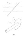
- Figure 4 shows a cut-away perspective view of an end of a roll mantle 28 in which the outermost parts of the coolant channels 32 may be seen.
- coolant will flow along a coolant channel 21 in a direction out of the plane of the paper towards part 32a of the coolant channel, and then in a direction along the plane of the paper to part 32b of the coolant channel, before it is returned via the coolant channel 21 in a direction into the plane of the paper to the coolant line 30 in the rotatable shaft 24.
- FIGS 5 and 6 show how coolant may be arranged to flow though a roll mantle 28.
- Coolant from a coolant line 30 in a rotatable shaft 24 may be made to flow, by means of a blocking element 25 according to the present invention, into a plurality of fluid inlets 32 that may be arranged around the inner surface 40 of the roll mantle 28 in the central region thereof. Coolant then flows along coolant channels 32 in the roll mantle 28 and is returned to the coolant line 30 in the rotatable shaft 24 via at least one fluid outlet 42 that may also be arranged around the inner surface 40 of the roll mantle 28 in the central region thereof.
- the fluid inlet 36 and the coolant outlet 42 are arranged adjacent to one another and preferably as close as possible.
- a fluid inlet 36 may for example be arranged at a distance from a coolant outlet 42 which is less than the maximum cross-sectional dimension of a coolant channel 32, for example less than the maximum diameter of a coolant channel 32 having a circular cross-section.
- the distance between a fluid inlet 36 and a coolant outlet 42 may for example be 0.5-10.0 mm to facilitate the supply of coolant thereto and the return of coolant therefrom respectively.
- Figure 6 shows two coolant channels 32 arranged of the same size and shape; a roll mantle 28 according to the present invention may however be arranged to comprise any number of coolant channels 32, such as 1 to 12 coolant channels 32, each of any size or shape.
- FIGS 7 and 8 show a blocking element 25 according to an embodiment of the invention.
- the blocking element 25 comprises at least one coolant line-coolant supplying channel 27 arranged at the perimeter, i.e. the periphery if the blocking element 25 has a circular cross section.
- the at least one coolant line-coolant supplying channel 27 supplies coolant from the coolant line 30 in the rotatable shaft 24 to at least one fluid inlet 36 of a coolant channel 32 of a roll mantle 28.
- the blocking element 25 also comprises at least one coolant channel-coolant receiving channel 29 at the perimeter of the blocking element 25 to receive coolant from at least one coolant outlet 42 of a coolant channel 32 of a roll mantle 28.
- the coolant line-coolant supplying channels 27 and the coolant channel-coolant receiving channels 29 are provided alternately around the periphery of the blocking element 25. Such channels 27 and 29 may however be arranged in any suitable manner.
- Figure 9 shows a cut-away perspective view of a roll mantle 28 comprising a blocking element 25 according to an embodiment of the invention.
- the blocking element 25 is located in the coolant line 30 of the rotatable shaft. 24 supporting the roll mantle 28 aligned with a radial coolant channel in the rotatable shaft 24 and at least one fluid inlet 32 in the roll mantle 28. Once a blocking element 25 has been aligned 25 it may be provided with locking means to lock the blocking element 25 in position in the coolant line 30.
- Figure 10 shows how coolant in the coolant line 30 flows through a blocking element 25 according to an embodiment of the invention.
- FIGS 11 and 12 schematically show a blocking element 25 according to an embodiment of the invention viewed from the side and in perspective.
- the blocking element 25 comprises a disc 40, such as an oval disc, that may be placed in a coolant line 30.
- the disc 40 may be of any shape.
- FIGS 13 and 14 schematically show a blocking element 25 according to another embodiment of the invention viewed in perspective and from the side.
- the blocking element 25 comprises a contoured disc 40 that may be placed in a coolant line 30,
- the contoured disc 40 in the illustrated embodiment creates two inlets and two outlets.
- a blocking element 25 according to the present invention may however be arranged to create any number of inlets and outlets.
- Figure 15 schematically shows show a blocking element 25 according to a further embodiment of the invention viewed in perspective.
- the blocking element 25 may be manufactured from any suitable material using any suitable method, such as a turning, milling or casting.
- a blocking element 25 according to an embodiment of the invention may be arranged to comprise at least one inlet and outlet that are axially or radially displaced with respect to each other.
- Figure 16 schematically shows a blocking element 25 according to another embodiment of the invention viewed in perspective.
- a blocking element 25 according to an embodiment of the invention may be arranged to be placed in a groove in a roll mantle 28 for example, in contact with the roll mantle 28 and a rotatable shaft 24.
- the roll mantles 28 in the illustrated embodiments have been shown as hollow cylinders having a continuous and smooth outer surface 28a. It should however be noted that the at least one roll mantle 28 of a roll line 20 according to the present invention need not necessarily be a cylinder or of a symmetric shape of uniform cross section, and its outer surface need not necessarily be continuous or smooth, but may be of any shape, size and design depending on their function and/or location in a continuous casting plant.
- the present invention concerns a roll mantle comprising at least one coolant channel that is arranged to be in fluid communication with a coolant line in a rotatable shaft when in use
- the so-called coolant channels in the roll mantle may be utilized for any purpose, i.e, they are not only suitable for transporting coolant through at least part of the roll mantle.
Landscapes
- Engineering & Computer Science (AREA)
- Mechanical Engineering (AREA)
- Continuous Casting (AREA)
- Rolls And Other Rotary Bodies (AREA)
- Furnace Details (AREA)
Applications Claiming Priority (1)
| Application Number | Priority Date | Filing Date | Title |
|---|---|---|---|
| SE1200410 | 2012-07-04 |
Publications (3)
| Publication Number | Publication Date |
|---|---|
| EP2682204A2 true EP2682204A2 (de) | 2014-01-08 |
| EP2682204A3 EP2682204A3 (de) | 2017-11-01 |
| EP2682204B1 EP2682204B1 (de) | 2020-11-04 |
Family
ID=48740797
Family Applications (1)
| Application Number | Title | Priority Date | Filing Date |
|---|---|---|---|
| EP13003268.3A Active EP2682204B1 (de) | 2012-07-04 | 2013-06-27 | Sperrelement, Rollleitung und Stranggießvorrichtung |
Country Status (5)
| Country | Link |
|---|---|
| EP (1) | EP2682204B1 (de) |
| KR (1) | KR101505306B1 (de) |
| CN (1) | CN103521729B (de) |
| BR (1) | BR102013017093A2 (de) |
| RU (1) | RU2553139C2 (de) |
Cited By (2)
| Publication number | Priority date | Publication date | Assignee | Title |
|---|---|---|---|---|
| US11285530B2 (en) * | 2019-09-16 | 2022-03-29 | Aktiebolaget Skf | Roll mantle, roll body and method of forming same |
| WO2023169747A1 (de) * | 2022-03-09 | 2023-09-14 | Sms Group Gmbh | Bogensegment einer strangführungseinrichtung |
Families Citing this family (3)
| Publication number | Priority date | Publication date | Assignee | Title |
|---|---|---|---|---|
| RU2553140C2 (ru) * | 2012-07-04 | 2015-06-10 | Актиеболагет Скф | Распределяющий элемент, роликовая линия и устройство для непрерывной разливки |
| KR102308295B1 (ko) * | 2019-11-18 | 2021-10-06 | 주식회사 포스코 | 연속주조용 가이드롤 |
| DE102020200001A1 (de) * | 2020-01-01 | 2021-07-01 | Aktiebolaget Skf | Rollenlinieneinheit & Stranggießanlage |
Citations (1)
| Publication number | Priority date | Publication date | Assignee | Title |
|---|---|---|---|---|
| EP1646463A1 (de) | 2003-07-18 | 2006-04-19 | Voest-Alpine Industrieanlagenbau GmbH & Co. | Innengek hlte strangf hrungsrolle |
Family Cites Families (17)
| Publication number | Priority date | Publication date | Assignee | Title |
|---|---|---|---|---|
| FR2258235B1 (de) * | 1974-01-21 | 1981-02-06 | Voest Ag | |
| DE2552969A1 (de) * | 1975-11-26 | 1977-06-02 | Kloeckner Werke Ag | Fuehrungsrolle fuer stranggussanlagen, mit auf einer mehrfach gelagerten achse angeordneten rollenabschnitten |
| DE2707907A1 (de) * | 1976-02-24 | 1977-08-25 | Trimay Engineering Co | Walze bzw. welle |
| SU850283A1 (ru) * | 1979-12-07 | 1981-07-30 | Днепропетровский Ордена Трудовогокрасного Знамени Металлургический Ин-Ститут | Ролик дл направлени и поддержани СлиТКА |
| US4603729A (en) * | 1983-06-17 | 1986-08-05 | Kabushiki Kaisha Kobe Seiko Sho | Piping assembly for use in roll section of continuous casting line |
| FR2587247B1 (fr) * | 1985-09-17 | 1988-08-12 | Siderurgie Fse Inst Rech | Cylindre pour coulee continue entre cylindres, a circulation de fluide de refroidissement |
| SU1502176A1 (ru) * | 1987-07-17 | 1989-08-23 | Уральский научно-исследовательский институт черных металлов | Ролик зоны вторичного охлаждени машины непрерывного лить заготовок |
| IT1276656B1 (it) * | 1995-04-03 | 1997-11-03 | Innocenti Eng Spa | Rullo per lingottiera di colata continua a rulli controrotanti per spessori sottili |
| KR19990055900A (ko) * | 1997-12-29 | 1999-07-15 | 이구택 | 연속주조기의 냉각대 롤 |
| FR2799399B1 (fr) * | 1999-10-06 | 2002-02-08 | Pechiney Rhenalu | Cylindre de coulee continue de bande metallique comprenant un circuit de refroidissement |
| DE10006630C1 (de) * | 2000-02-14 | 2001-07-19 | Thyssenkrupp Stahl Ag | Drehdurchführung an einer flüssigkeitsgekühlten Rolle, insbesondere einer Transportrolle eines Rollenherdofens |
| AT412327B (de) * | 2003-04-23 | 2005-01-25 | Voest Alpine Ind Anlagen | Strangführungsrolle |
| AT502694B1 (de) * | 2005-10-20 | 2007-10-15 | Voest Alpine Industrienanlagen | Strangführungsrolle |
| DE102006040011A1 (de) * | 2006-04-21 | 2007-10-25 | Sms Demag Ag | Strangführungsrolle |
| KR20080058086A (ko) * | 2006-12-21 | 2008-06-25 | 주식회사 포스코 | 연속주조기의 냉각대 연주롤 |
| DE102008029944A1 (de) * | 2008-06-26 | 2009-12-31 | Sms Siemag Aktiengesellschaft | Modulare Strangführungsrolle |
| CN201791936U (zh) * | 2010-09-17 | 2011-04-13 | 中国重型机械研究院有限公司 | 一种板坯连铸机导辊 |
-
2013
- 2013-06-20 RU RU2013128350/02A patent/RU2553139C2/ru active
- 2013-06-27 EP EP13003268.3A patent/EP2682204B1/de active Active
- 2013-07-02 KR KR1020130076879A patent/KR101505306B1/ko not_active IP Right Cessation
- 2013-07-02 BR BR102013017093A patent/BR102013017093A2/pt not_active IP Right Cessation
- 2013-07-04 CN CN201310394720.6A patent/CN103521729B/zh active Active
Patent Citations (1)
| Publication number | Priority date | Publication date | Assignee | Title |
|---|---|---|---|---|
| EP1646463A1 (de) | 2003-07-18 | 2006-04-19 | Voest-Alpine Industrieanlagenbau GmbH & Co. | Innengek hlte strangf hrungsrolle |
Cited By (3)
| Publication number | Priority date | Publication date | Assignee | Title |
|---|---|---|---|---|
| US11285530B2 (en) * | 2019-09-16 | 2022-03-29 | Aktiebolaget Skf | Roll mantle, roll body and method of forming same |
| US11766714B2 (en) | 2019-09-16 | 2023-09-26 | Aktiebolaget Skf | Method of forming a roll body or roll mantle |
| WO2023169747A1 (de) * | 2022-03-09 | 2023-09-14 | Sms Group Gmbh | Bogensegment einer strangführungseinrichtung |
Also Published As
| Publication number | Publication date |
|---|---|
| CN103521729A (zh) | 2014-01-22 |
| KR20140005094A (ko) | 2014-01-14 |
| EP2682204A3 (de) | 2017-11-01 |
| RU2013128350A (ru) | 2014-12-27 |
| RU2553139C2 (ru) | 2015-06-10 |
| EP2682204B1 (de) | 2020-11-04 |
| CN103521729B (zh) | 2016-04-06 |
| BR102013017093A2 (pt) | 2016-09-13 |
| KR101505306B1 (ko) | 2015-03-23 |
Similar Documents
| Publication | Publication Date | Title |
|---|---|---|
| EP2682204B1 (de) | Sperrelement, Rollleitung und Stranggießvorrichtung | |
| CN107000043B (zh) | 用于通过控制辊凸度而连续地铸造铸带的方法和装置 | |
| KR20060035768A (ko) | 내부 냉각식 빌레트 안내 롤러 | |
| US5279535A (en) | Internally cooled roller | |
| KR101189517B1 (ko) | 내부 냉각식 가이드 롤 | |
| EP2682203A2 (de) | Sperrelement, Rollleitung und Stranggießvorrichtung | |
| EP2682202B1 (de) | Rollleitung und Stranggießvorrichtung | |
| KR20090067620A (ko) | 롤 냉각 장치 | |
| US11305339B2 (en) | Roll line unit and continuous casting apparatus | |
| US11766714B2 (en) | Method of forming a roll body or roll mantle | |
| US20070017651A1 (en) | Twin roll caster, and equipment and method for operating the same | |
| KR101449253B1 (ko) | 연속 주조용 가이드 롤 | |
| EP2680990B1 (de) | Verfahren zur verlängerung der lebensdauer einer walzlinie | |
| EP4006369B1 (de) | Lagergehäuse für eine rotierende walze, kühlverfahren für dieses lagergehäuse, stahlstranggussmaschine und -verfahren | |
| AU711139B2 (en) | Method and device for guiding strands in a continuous casting installation | |
| SE1651347A1 (sv) | Roller for a continuous casting machine | |
| CN114364471B (zh) | 用于连续浇铸金属产品的结晶器以及相应的浇铸方法 | |
| KR20130075277A (ko) | 연속주조장치의 가이드롤러 조립체 |
Legal Events
| Date | Code | Title | Description |
|---|---|---|---|
| PUAI | Public reference made under article 153(3) epc to a published international application that has entered the european phase |
Free format text: ORIGINAL CODE: 0009012 |
|
| AK | Designated contracting states |
Kind code of ref document: A2 Designated state(s): AL AT BE BG CH CY CZ DE DK EE ES FI FR GB GR HR HU IE IS IT LI LT LU LV MC MK MT NL NO PL PT RO RS SE SI SK SM TR |
|
| AX | Request for extension of the european patent |
Extension state: BA ME |
|
| PUAL | Search report despatched |
Free format text: ORIGINAL CODE: 0009013 |
|
| AK | Designated contracting states |
Kind code of ref document: A3 Designated state(s): AL AT BE BG CH CY CZ DE DK EE ES FI FR GB GR HR HU IE IS IT LI LT LU LV MC MK MT NL NO PL PT RO RS SE SI SK SM TR |
|
| AX | Request for extension of the european patent |
Extension state: BA ME |
|
| RIC1 | Information provided on ipc code assigned before grant |
Ipc: B22D 11/128 20060101AFI20170927BHEP |
|
| STAA | Information on the status of an ep patent application or granted ep patent |
Free format text: STATUS: REQUEST FOR EXAMINATION WAS MADE |
|
| 17P | Request for examination filed |
Effective date: 20171220 |
|
| RBV | Designated contracting states (corrected) |
Designated state(s): AL AT BE BG CH CY CZ DE DK EE ES FI FR GB GR HR HU IE IS IT LI LT LU LV MC MK MT NL NO PL PT RO RS SE SI SK SM TR |
|
| STAA | Information on the status of an ep patent application or granted ep patent |
Free format text: STATUS: EXAMINATION IS IN PROGRESS |
|
| 17Q | First examination report despatched |
Effective date: 20181018 |
|
| GRAP | Despatch of communication of intention to grant a patent |
Free format text: ORIGINAL CODE: EPIDOSNIGR1 |
|
| STAA | Information on the status of an ep patent application or granted ep patent |
Free format text: STATUS: GRANT OF PATENT IS INTENDED |
|
| INTG | Intention to grant announced |
Effective date: 20200605 |
|
| GRAS | Grant fee paid |
Free format text: ORIGINAL CODE: EPIDOSNIGR3 |
|
| GRAA | (expected) grant |
Free format text: ORIGINAL CODE: 0009210 |
|
| STAA | Information on the status of an ep patent application or granted ep patent |
Free format text: STATUS: THE PATENT HAS BEEN GRANTED |
|
| AK | Designated contracting states |
Kind code of ref document: B1 Designated state(s): AL AT BE BG CH CY CZ DE DK EE ES FI FR GB GR HR HU IE IS IT LI LT LU LV MC MK MT NL NO PL PT RO RS SE SI SK SM TR |
|
| REG | Reference to a national code |
Ref country code: GB Ref legal event code: FG4D |
|
| REG | Reference to a national code |
Ref country code: CH Ref legal event code: EP |
|
| REG | Reference to a national code |
Ref country code: AT Ref legal event code: REF Ref document number: 1330147 Country of ref document: AT Kind code of ref document: T Effective date: 20201115 |
|
| REG | Reference to a national code |
Ref country code: IE Ref legal event code: FG4D |
|
| REG | Reference to a national code |
Ref country code: DE Ref legal event code: R096 Ref document number: 602013073729 Country of ref document: DE |
|
| REG | Reference to a national code |
Ref country code: NL Ref legal event code: MP Effective date: 20201104 |
|
| PG25 | Lapsed in a contracting state [announced via postgrant information from national office to epo] |
Ref country code: FI Free format text: LAPSE BECAUSE OF FAILURE TO SUBMIT A TRANSLATION OF THE DESCRIPTION OR TO PAY THE FEE WITHIN THE PRESCRIBED TIME-LIMIT Effective date: 20201104 Ref country code: RS Free format text: LAPSE BECAUSE OF FAILURE TO SUBMIT A TRANSLATION OF THE DESCRIPTION OR TO PAY THE FEE WITHIN THE PRESCRIBED TIME-LIMIT Effective date: 20201104 Ref country code: PT Free format text: LAPSE BECAUSE OF FAILURE TO SUBMIT A TRANSLATION OF THE DESCRIPTION OR TO PAY THE FEE WITHIN THE PRESCRIBED TIME-LIMIT Effective date: 20210304 Ref country code: NO Free format text: LAPSE BECAUSE OF FAILURE TO SUBMIT A TRANSLATION OF THE DESCRIPTION OR TO PAY THE FEE WITHIN THE PRESCRIBED TIME-LIMIT Effective date: 20210204 Ref country code: GR Free format text: LAPSE BECAUSE OF FAILURE TO SUBMIT A TRANSLATION OF THE DESCRIPTION OR TO PAY THE FEE WITHIN THE PRESCRIBED TIME-LIMIT Effective date: 20210205 |
|
| PG25 | Lapsed in a contracting state [announced via postgrant information from national office to epo] |
Ref country code: BG Free format text: LAPSE BECAUSE OF FAILURE TO SUBMIT A TRANSLATION OF THE DESCRIPTION OR TO PAY THE FEE WITHIN THE PRESCRIBED TIME-LIMIT Effective date: 20210204 Ref country code: ES Free format text: LAPSE BECAUSE OF FAILURE TO SUBMIT A TRANSLATION OF THE DESCRIPTION OR TO PAY THE FEE WITHIN THE PRESCRIBED TIME-LIMIT Effective date: 20201104 Ref country code: SE Free format text: LAPSE BECAUSE OF FAILURE TO SUBMIT A TRANSLATION OF THE DESCRIPTION OR TO PAY THE FEE WITHIN THE PRESCRIBED TIME-LIMIT Effective date: 20201104 Ref country code: LV Free format text: LAPSE BECAUSE OF FAILURE TO SUBMIT A TRANSLATION OF THE DESCRIPTION OR TO PAY THE FEE WITHIN THE PRESCRIBED TIME-LIMIT Effective date: 20201104 Ref country code: IS Free format text: LAPSE BECAUSE OF FAILURE TO SUBMIT A TRANSLATION OF THE DESCRIPTION OR TO PAY THE FEE WITHIN THE PRESCRIBED TIME-LIMIT Effective date: 20210304 Ref country code: PL Free format text: LAPSE BECAUSE OF FAILURE TO SUBMIT A TRANSLATION OF THE DESCRIPTION OR TO PAY THE FEE WITHIN THE PRESCRIBED TIME-LIMIT Effective date: 20201104 |
|
| REG | Reference to a national code |
Ref country code: LT Ref legal event code: MG9D |
|
| PG25 | Lapsed in a contracting state [announced via postgrant information from national office to epo] |
Ref country code: HR Free format text: LAPSE BECAUSE OF FAILURE TO SUBMIT A TRANSLATION OF THE DESCRIPTION OR TO PAY THE FEE WITHIN THE PRESCRIBED TIME-LIMIT Effective date: 20201104 |
|
| PG25 | Lapsed in a contracting state [announced via postgrant information from national office to epo] |
Ref country code: LT Free format text: LAPSE BECAUSE OF FAILURE TO SUBMIT A TRANSLATION OF THE DESCRIPTION OR TO PAY THE FEE WITHIN THE PRESCRIBED TIME-LIMIT Effective date: 20201104 Ref country code: SK Free format text: LAPSE BECAUSE OF FAILURE TO SUBMIT A TRANSLATION OF THE DESCRIPTION OR TO PAY THE FEE WITHIN THE PRESCRIBED TIME-LIMIT Effective date: 20201104 Ref country code: RO Free format text: LAPSE BECAUSE OF FAILURE TO SUBMIT A TRANSLATION OF THE DESCRIPTION OR TO PAY THE FEE WITHIN THE PRESCRIBED TIME-LIMIT Effective date: 20201104 Ref country code: EE Free format text: LAPSE BECAUSE OF FAILURE TO SUBMIT A TRANSLATION OF THE DESCRIPTION OR TO PAY THE FEE WITHIN THE PRESCRIBED TIME-LIMIT Effective date: 20201104 Ref country code: CZ Free format text: LAPSE BECAUSE OF FAILURE TO SUBMIT A TRANSLATION OF THE DESCRIPTION OR TO PAY THE FEE WITHIN THE PRESCRIBED TIME-LIMIT Effective date: 20201104 Ref country code: SM Free format text: LAPSE BECAUSE OF FAILURE TO SUBMIT A TRANSLATION OF THE DESCRIPTION OR TO PAY THE FEE WITHIN THE PRESCRIBED TIME-LIMIT Effective date: 20201104 |
|
| REG | Reference to a national code |
Ref country code: DE Ref legal event code: R097 Ref document number: 602013073729 Country of ref document: DE |
|
| REG | Reference to a national code |
Ref country code: AT Ref legal event code: UEP Ref document number: 1330147 Country of ref document: AT Kind code of ref document: T Effective date: 20201104 |
|
| PG25 | Lapsed in a contracting state [announced via postgrant information from national office to epo] |
Ref country code: DK Free format text: LAPSE BECAUSE OF FAILURE TO SUBMIT A TRANSLATION OF THE DESCRIPTION OR TO PAY THE FEE WITHIN THE PRESCRIBED TIME-LIMIT Effective date: 20201104 |
|
| PLBE | No opposition filed within time limit |
Free format text: ORIGINAL CODE: 0009261 |
|
| STAA | Information on the status of an ep patent application or granted ep patent |
Free format text: STATUS: NO OPPOSITION FILED WITHIN TIME LIMIT |
|
| 26N | No opposition filed |
Effective date: 20210805 |
|
| PG25 | Lapsed in a contracting state [announced via postgrant information from national office to epo] |
Ref country code: NL Free format text: LAPSE BECAUSE OF FAILURE TO SUBMIT A TRANSLATION OF THE DESCRIPTION OR TO PAY THE FEE WITHIN THE PRESCRIBED TIME-LIMIT Effective date: 20201104 Ref country code: AL Free format text: LAPSE BECAUSE OF FAILURE TO SUBMIT A TRANSLATION OF THE DESCRIPTION OR TO PAY THE FEE WITHIN THE PRESCRIBED TIME-LIMIT Effective date: 20201104 |
|
| PG25 | Lapsed in a contracting state [announced via postgrant information from national office to epo] |
Ref country code: SI Free format text: LAPSE BECAUSE OF FAILURE TO SUBMIT A TRANSLATION OF THE DESCRIPTION OR TO PAY THE FEE WITHIN THE PRESCRIBED TIME-LIMIT Effective date: 20201104 |
|
| PG25 | Lapsed in a contracting state [announced via postgrant information from national office to epo] |
Ref country code: MC Free format text: LAPSE BECAUSE OF FAILURE TO SUBMIT A TRANSLATION OF THE DESCRIPTION OR TO PAY THE FEE WITHIN THE PRESCRIBED TIME-LIMIT Effective date: 20201104 |
|
| REG | Reference to a national code |
Ref country code: CH Ref legal event code: PL |
|
| GBPC | Gb: european patent ceased through non-payment of renewal fee |
Effective date: 20210627 |
|
| REG | Reference to a national code |
Ref country code: BE Ref legal event code: MM Effective date: 20210630 |
|
| PG25 | Lapsed in a contracting state [announced via postgrant information from national office to epo] |
Ref country code: LU Free format text: LAPSE BECAUSE OF NON-PAYMENT OF DUE FEES Effective date: 20210627 |
|
| PG25 | Lapsed in a contracting state [announced via postgrant information from national office to epo] |
Ref country code: LI Free format text: LAPSE BECAUSE OF NON-PAYMENT OF DUE FEES Effective date: 20210630 Ref country code: IE Free format text: LAPSE BECAUSE OF NON-PAYMENT OF DUE FEES Effective date: 20210627 Ref country code: GB Free format text: LAPSE BECAUSE OF NON-PAYMENT OF DUE FEES Effective date: 20210627 Ref country code: CH Free format text: LAPSE BECAUSE OF NON-PAYMENT OF DUE FEES Effective date: 20210630 |
|
| PG25 | Lapsed in a contracting state [announced via postgrant information from national office to epo] |
Ref country code: IS Free format text: LAPSE BECAUSE OF FAILURE TO SUBMIT A TRANSLATION OF THE DESCRIPTION OR TO PAY THE FEE WITHIN THE PRESCRIBED TIME-LIMIT Effective date: 20210304 Ref country code: FR Free format text: LAPSE BECAUSE OF NON-PAYMENT OF DUE FEES Effective date: 20210630 |
|
| PG25 | Lapsed in a contracting state [announced via postgrant information from national office to epo] |
Ref country code: BE Free format text: LAPSE BECAUSE OF NON-PAYMENT OF DUE FEES Effective date: 20210630 |
|
| PG25 | Lapsed in a contracting state [announced via postgrant information from national office to epo] |
Ref country code: HU Free format text: LAPSE BECAUSE OF FAILURE TO SUBMIT A TRANSLATION OF THE DESCRIPTION OR TO PAY THE FEE WITHIN THE PRESCRIBED TIME-LIMIT; INVALID AB INITIO Effective date: 20130627 |
|
| P01 | Opt-out of the competence of the unified patent court (upc) registered |
Effective date: 20230513 |
|
| PG25 | Lapsed in a contracting state [announced via postgrant information from national office to epo] |
Ref country code: CY Free format text: LAPSE BECAUSE OF FAILURE TO SUBMIT A TRANSLATION OF THE DESCRIPTION OR TO PAY THE FEE WITHIN THE PRESCRIBED TIME-LIMIT Effective date: 20201104 |
|
| PGFP | Annual fee paid to national office [announced via postgrant information from national office to epo] |
Ref country code: IT Payment date: 20230620 Year of fee payment: 11 |
|
| PG25 | Lapsed in a contracting state [announced via postgrant information from national office to epo] |
Ref country code: MK Free format text: LAPSE BECAUSE OF FAILURE TO SUBMIT A TRANSLATION OF THE DESCRIPTION OR TO PAY THE FEE WITHIN THE PRESCRIBED TIME-LIMIT Effective date: 20201104 |
|
| PG25 | Lapsed in a contracting state [announced via postgrant information from national office to epo] |
Ref country code: TR Free format text: LAPSE BECAUSE OF FAILURE TO SUBMIT A TRANSLATION OF THE DESCRIPTION OR TO PAY THE FEE WITHIN THE PRESCRIBED TIME-LIMIT Effective date: 20201104 |
|
| PGFP | Annual fee paid to national office [announced via postgrant information from national office to epo] |
Ref country code: DE Payment date: 20240627 Year of fee payment: 12 |
|
| PGFP | Annual fee paid to national office [announced via postgrant information from national office to epo] |
Ref country code: AT Payment date: 20240618 Year of fee payment: 12 |