EP2682016A1 - Ornamental component with gripping element - Google Patents
Ornamental component with gripping element Download PDFInfo
- Publication number
- EP2682016A1 EP2682016A1 EP20130154843 EP13154843A EP2682016A1 EP 2682016 A1 EP2682016 A1 EP 2682016A1 EP 20130154843 EP20130154843 EP 20130154843 EP 13154843 A EP13154843 A EP 13154843A EP 2682016 A1 EP2682016 A1 EP 2682016A1
- Authority
- EP
- European Patent Office
- Prior art keywords
- tubular element
- hole
- ornamental component
- self
- gripping
- Prior art date
- Legal status (The legal status is an assumption and is not a legal conclusion. Google has not performed a legal analysis and makes no representation as to the accuracy of the status listed.)
- Granted
Links
Images


Classifications
-
- A—HUMAN NECESSITIES
- A44—HABERDASHERY; JEWELLERY
- A44C—PERSONAL ADORNMENTS, e.g. JEWELLERY; COINS
- A44C11/00—Watch chains; Ornamental chains
- A44C11/002—Ornamental chains composed of pearls
-
- A—HUMAN NECESSITIES
- A44—HABERDASHERY; JEWELLERY
- A44C—PERSONAL ADORNMENTS, e.g. JEWELLERY; COINS
- A44C25/00—Miscellaneous fancy ware for personal wear, e.g. pendants, crosses, crucifixes, charms
-
- A—HUMAN NECESSITIES
- A44—HABERDASHERY; JEWELLERY
- A44C—PERSONAL ADORNMENTS, e.g. JEWELLERY; COINS
- A44C11/00—Watch chains; Ornamental chains
-
- A—HUMAN NECESSITIES
- A44—HABERDASHERY; JEWELLERY
- A44C—PERSONAL ADORNMENTS, e.g. JEWELLERY; COINS
- A44C15/00—Other forms of jewellery
- A44C15/0045—Jewellery specially adapted to be worn on a specific part of the body not fully provided for in groups A44C1/00 - A44C9/00
- A44C15/005—Necklaces
-
- A—HUMAN NECESSITIES
- A44—HABERDASHERY; JEWELLERY
- A44C—PERSONAL ADORNMENTS, e.g. JEWELLERY; COINS
- A44C25/00—Miscellaneous fancy ware for personal wear, e.g. pendants, crosses, crucifixes, charms
- A44C25/001—Pendants
-
- A—HUMAN NECESSITIES
- A44—HABERDASHERY; JEWELLERY
- A44C—PERSONAL ADORNMENTS, e.g. JEWELLERY; COINS
- A44C27/00—Making jewellery or other personal adornments
-
- A—HUMAN NECESSITIES
- A44—HABERDASHERY; JEWELLERY
- A44C—PERSONAL ADORNMENTS, e.g. JEWELLERY; COINS
- A44C5/00—Bracelets; Wrist-watch straps; Fastenings for bracelets or wrist-watch straps
-
- Y—GENERAL TAGGING OF NEW TECHNOLOGICAL DEVELOPMENTS; GENERAL TAGGING OF CROSS-SECTIONAL TECHNOLOGIES SPANNING OVER SEVERAL SECTIONS OF THE IPC; TECHNICAL SUBJECTS COVERED BY FORMER USPC CROSS-REFERENCE ART COLLECTIONS [XRACs] AND DIGESTS
- Y10—TECHNICAL SUBJECTS COVERED BY FORMER USPC
- Y10T—TECHNICAL SUBJECTS COVERED BY FORMER US CLASSIFICATION
- Y10T24/00—Buckles, buttons, clasps, etc.
- Y10T24/39—Cord and rope holders
-
- Y—GENERAL TAGGING OF NEW TECHNOLOGICAL DEVELOPMENTS; GENERAL TAGGING OF CROSS-SECTIONAL TECHNOLOGIES SPANNING OVER SEVERAL SECTIONS OF THE IPC; TECHNICAL SUBJECTS COVERED BY FORMER USPC CROSS-REFERENCE ART COLLECTIONS [XRACs] AND DIGESTS
- Y10—TECHNICAL SUBJECTS COVERED BY FORMER USPC
- Y10T—TECHNICAL SUBJECTS COVERED BY FORMER US CLASSIFICATION
- Y10T29/00—Metal working
- Y10T29/49—Method of mechanical manufacture
- Y10T29/49588—Jewelry or locket making
- Y10T29/4959—Human adornment device making
- Y10T29/49591—Bracelet making
Definitions
- the present invention relates to an ornamental component for a bracelet or necklace, to a bracelet or necklace comprising such an ornamental component, to a method of manufacturing an ornamental component, and a tubular element for securing a gripping element inside a through hole of an ornamental component.
- Jewellery such as necklaces and bracelets, often consists of a plurality of freely movable ornamental components e.g. beads strung on an elongated member e.g. chain, wire, or string.
- an ornamental component provided with a stopping mechanism configured to grip the necklace or bracelet may be used.
- Such stopping mechanisms are known from the prior art in a variety of forms.
- the invention relates to an ornamental component for a bracelet and / or a necklace, said ornamental component having a through hole allowing said ornamental component to be strung on an elongated member of a bracelet and / or necklace, said through hole defining a through hole axis; said ornamental component comprising:
- the production costs may be lowered.
- the gripping element may be more efficiently protected from damage.
- An ornamental component may be any component that can be strung on a bracelet and / or necklace for ornamental purposes such as a bead.
- An ornamental component according to the first aspect of the invention may be used to organize freely movable beads on a bracelet or necklace, e.g. two ornamental components may be pulled to a desired position on an elongated member of a bracelet or necklace and released, whereby they resiliently grip the elongated member. Consequently, the bracelet or necklace is divided into three distinct zones for freely movable beads. This may be used to prevent all the freely movable beads from grouping together.
- the self-supporting housing may constitute the outer surface of the ornamental component or may be covered with another layer or element constituting the outer surface of the ornamental component.
- the self-supporting housing may have any shape such as approximately spherical, cylindrical or cubical.
- the self-supporting housing has a structural strength allowing it to be securely handled during the manufacturing process of the ornamental component.
- the self-supporting housing may provide the primary structural strength of the ornamental component.
- the self-supporting housing may be made of metal, glass, wood, plastic or a combination thereof.
- the trough hole of the self-supporting housing may have a constant width or may have a varying width (measured in planes being perpendicular to the through hole axis), e.g.
- the through hole of the self-supporting housing may be wider in the central part of self-supporting housing than at the first opening and the second opening.
- the inner surface of the through hole of the self-supporting housing may be spaced apart from the insert assembly by another element or a fluid e.g. air.
- At least a part of the self-supporting housing may be transparent or semi-transparent.
- the individual element of the insert assembly may be permanently attached or non-permanently attached.
- the insert assembly may be inserted into the through hole of the housing through the first opening of the housing, i.e. the insert assembly may have a size and shape allowing it to be insertable through the first opening of the self-supporting housing.
- the first tubular element may have any outer shape such as round or rectangular.
- the through hole of the first tubular element may have any shape such as round or rectangular.
- the first tubular element may be integrally molded, i.e. made from a single mold.
- the first tubular element may be made of metal and / or plastic.
- the gripping element may be made of a material configured to establish a high frictional connection with an elongated member of a bracelet and / or necklace, e.g. a chain, band, or strand of a necklace or bracelet.
- the gripping element may be made of a deformable material such as a silicone material.
- said gripping element is made of a first material and said first tubular element is made of a second material, wherein said coefficient of friction of said first material is higher than said coefficient of friction of said second material relative to sterling silver.
- the coefficient of friction of the first material may be at least 10%, 20%, 40% or 60% higher than the coefficient of friction of the second material relative to sterling silver.
- the gripping element is positioned in a central part of the ornamental component and have a width along the through hole axis of less than 95%, 90%, 80%, 70%, 60% or 50% of the width of the self-supporting housing along the through hole axis.
- said first tubular element comprises a first circumferential opening extending along the through hole axis
- said gripping element comprises a first gripping portion for frictionally gripping said elongated member of said bracelet and / or necklace, wherein said first gripping part extends through said first circumferential opening
- said gripping element comprises a tubular portion, said first gripping portion protrudes from an interior surface of said tubular portion, and wherein said tubular portion of said gripping element surrounds a part of said first tubular element.
- tubular element may in an efficient manner secure said gripping element inside said through hole of said ornamental component.
- the entire gripping element may be integrally molded, i.e. made from a single mold.
- said first tubular element comprises a second circumferential opening extending along the through hole axis and said gripping element comprises a second gripping portion protruding from an interior surface of said tubular portion of said gripping element, wherein said second gripping portion extends through said second circumferential opening.
- said first tubular element comprises a third circumferential opening extending along the through hole axis and said gripping element comprises a third gripping portion protruding from an interior surface of said tubular potion of said gripping element, and wherein said third gripping portion extends through said third circumferential opening.
- the first circumferential opening, the second circumferential opening and / or the third circumferential opening have a width along the through hole axis of less than 95%, 90%, 80%, 70%, 60% or 50% of the width of the first tubular element along the through hole axis.
- each of the first circumferential opening, the second circumferential opening and / or the third circumferential opening extends between 5% and 33% of the circumference of the first tubular element in a plane being perpendicular to the through hole axis.
- the first tubular element comprises a first portion and a second portion, wherein the second potion has a lower widest width than the widest width of the first portion, and wherein the tubular portion of the gripping element is arranged to fit snugly around the second portion of the first tubular element, and abutting the first portion of the first tubular element whereby the gripping element is prevented from moving in a first direction along the through hole axis relative to the first tubular element.
- the first tubular element further comprises a third portion, and wherein the second potion has a lower widest width than the widest width of the first portion and the third portion, and wherein the tubular portion of the gripping element further abuts the third portion of the first tubular element thereby preventing the gripping element from moving in any direction along the through hole axis relative to the first tubular element.
- the widest width is measured in a plane being perpendicular to the through hole axis.
- said tubular portion of said gripping element has a widest width approximately equal to the widest width of the first portion and /or third portion of the first tubular element.
- the ornamental component further comprises a second tubular element, and wherein said first tubular element is positioned inside said second tubular element.
- the second tubular element may additionally hide non-decorative elements of the ornamental component, when the self-supporting housing is transparent or semi-transparent.
- the second tubular element may have a width along the through hole axis being approximately equal to the width of the self-supporting housing.
- the second tubular element may be fully inserted into the through hole of the self-supporting housing.
- said first tubular element of said insert assembly at a first end further comprises a collar, wherein said collar is positioned outside said self-supporting housing at the first opening of said self-supporting housing and comprises a surface abutting an outer surface of said self-supporting housing thereby preventing said first tubular element of said insert assembly from moving in a first direction along said through hole axis relative to said ornamental component.
- the outer surface may be an outer surface of said self-supporting housing.
- the collar may be an integral portion of the first tubular element or may be attached to the first tubular element.
- said ornamental component further comprises a locking element having a through hole wherein said locking element comprises an engagement portion positioned inside said self-supporting housing and a collar positioned outside said self-supporting housing at the second opening of said self-supporting housing, wherein said engagement portion is attached to said first tubular element and said collar comprises a surface abutting an outer surface of said self-supporting housing thereby preventing said first tubular element of said insert assembly from moving in a second direction along said through hole axis relative to said ornamental component.
- the insert assembly is in an effective manner secured to the self-supporting housing.
- the outer surface may be an outer surface of said self-supporting housing.
- the engagement portion and the collar of the locking element may be integrally formed.
- the locking element may be attached to the first tubular element by the use of glue or a mechanical locking mechanism.
- said engagement part of said locking element is inserted into said first tubular element whereby said through hole of said locking element and said through hole of said first tubular element together forms the through hole of said ornamental component.
- said engagement portion is attached to said first tubular element by a male / female locking mechanism, wherein the male part comprises a protruding portion and the female part comprises a recess and / or opening.
- the engagement portion may be the male part and the first tubular element may be the female part, i.e. the engagement portion may comprise a protruding portion configured to engage with recess and / or opening in the first tubular element.
- the first tubular element may be the male part and the engagement portion may be the female part.
- the male / female locking mechanism is of the snap lock type wherein a translation and / or rotation from a free rotational orientation and / or position of the male and female part to a locked rotational orientation and / or position of the male and female part requires less force than a translation and / or rotation from a locked rotational orientation and / or position of the male and female part to a free rotational orientation and / or position of the male and female part.
- the male / female locking mechanism may be of the rotational lock type, wherein the female part (the engagement portion or the first tubular element) comprises a recess and / or opening configured to allow the protruding portion of the male part to translate inside the recess and / or opening along the through hole axis when the locking element is in a free rotational orientation relative to the first tubular element, and to be prevented from moving in at least a first direction along the through hole axis when the locking element is in a locked position relative to the first tubular element and the locking element is in a locked rotational orientation relative to the first tubular element.
- the male part comprises a plurality of protruding portions and the female part comprises a plurality of recess and / or openings.
- the locking element may be attached to the first tubular element by firstly rotationally orienting the locking element in the free rotational orientation relative to the first tubular element, next translating the first tubular element and / or the locking element along the through hole axis until the locking element is in the locked position relative to the first tubular element, and finally rotating the first tubular element and / or the locking element from the free rotational orientation to the locked rotational orientation.
- the protruding portion of the male part and / or the recess and / or opening of the female part may be configured so that a rotation from the free rotational orientation to the locked rotational orientation requires less force than a rotation from the locked rotational orientation to the free rotational orientation.
- the male part (the engagement portion or the first tubular element) comprises a flexible member configured to deform from a first shape to a second shape when the male part comes into contact with the female part, and further to snap back into approximately the first shape when the flexible member is aligned with the recess and / or opening of the female part, whereby the flexible member engages with the recess and / or opening and locks the male part to the female part, allowing the locking element to be attached to the first tubular element by a pure translation between the two.
- the male part comprises two flexible members, and the female part comprises two recesses and / or openings.
- the two flexible members may be arranged at opposite sides of the male part.
- the two recesses and / or openings may be arranged at opposite sides of the female part.
- the ornamental component has a length along the through hole axis between 2 mm and 5 cm.
- the invention relates to a bracelet or a necklace comprising:
- the elongated member may be any elongated member suitable for jewellery such as a metal chain, leather string, a fabric string, or an anchor type chain.
- the particular force is higher than the maximum gravitational force gravity acting on the ornamental component.
- the bracelet or necklace further comprises at least one freely movable ornamental component strung on said elongated member.
- the bracelet or necklace further comprises a plurality of freely movable ornamental components strung on said elongated member.
- the bracelet or necklace further comprises a second ornamental component as disclosed in relation to the first aspect of the invention strung on said elongated member; wherein the second ornamental component is configured so that the gripping element resiliently grips the elongated member to fix the second ornamental component along the elongated member until a particular force is acting on said second ornamental component, whereby the second ornamental component can be moved along the elongated member.
- the invention relates to a method for manufacturing an ornamental component, said ornamental component having a through hole allowing said ornamental component to be strung on an elongated member of a bracelet and / or necklace, said through hole defining a through hole axis, comprising the steps of:
- the insert assembly is inserted in said through hole of said self-supporting housing through said first opening of said self-supporting housing.
- the ornamental component is an ornamental component as disclosed in relation to the first aspect of the invention.
- said insert assembly is assembled before it is inserted into said through hole of said self-supporting housing.
- said first tubular element comprises a first circumferential opening extending along the through hole axis
- said gripping element comprises a first gripping portion, for frictionally gripping said elongated member of said bracelet and / or necklace, and a tubular portion, wherein said first gripping portion is protruding from an inner surface of said tubular portion
- the step of assembling said insert assembly comprises pulling said gripping element around said first tubular element until said first gripping portion is aligned with said first circumferential opening, whereby said first gripping portion extends through said first circumferential opening and a part of said inner surface of said tubular portion rests upon a part of the outer surface of said first tubular element thereby securing said gripping element to said first tubular element.
- said first tubular element further comprises a second circumferential opening extending along the through hole axis
- said gripping element further comprises a second gripping portion for frictionally gripping said elongated member of said bracelet and / or necklace, wherein said second gripping portion is protruding from an inner surface of said tubular portion
- the step of assembling said insert assembly comprises pulling said gripping element around said first tubular element until said first gripping portion is aligned with said firsts circumferential opening and said second gripping portion is aligned with said second circumferential opening, whereby said first gripping portion extends through said first circumferential opening, said second gripping portion extends through said second circumferential opening, and a part of said inner surface of said tubular portion rests upon a part of the outer surface of said first tubular element thereby attaching said gripping element to said first tubular element.
- said first tubular element further comprises a third circumferential opening extending along the through hole axis
- said gripping element further comprises a third gripping portion for frictionally gripping said elongated member of said bracelet and / or necklace, wherein said third gripping portion is protruding from an inner surface of said tubular portion
- the step of assembling said insert assembly comprises pulling said gripping element around said first tubular element until said first gripping portion is aligned with said first circumferential opening, said second gripping portion is aligned with said second circumferential opening, and said third gripping portion is aligned with said third circumferential opening, whereby said first gripping portion extends through said first circumferential opening, said second gripping portion extends through said second circumferential opening, said third gripping portion extends through said third circumferential opening, and a part of said inner surface of said tubular portion rests upon a part of the outer surface of said first tubular element thereby attaching said gripping element to said first tubular element.
- said ornamental component further comprises a locking element having a through hole, wherein said locking element comprises an engagement part for engaging with said insert assembly and a collar for being positioned outside said self-supporting housing, said method further comprising the step of:
- said engagement part is attached to said insert assembly by a male / female locking mechanism.
- the invention relates to a tubular element for securing a griping element, for gripping an elongated member of a bracelet and / necklace, in a through hole of an ornamental component, said tubular element having a through hole defining a tubular element through hole axis, wherein said tubular element comprises a first circumferential opening extending along the tubular element through hole axis for receiving a first gripping portion of said gripping element allowing said first gripping portion to extend through said first circumferential opening.
- said tubular element further comprises a second circumferential opening extending along the tubular element through hole axis for receiving a second gripping portion of said gripping element allowing said second gripping portion to extend through said second circumferential opening.
- said tubular element further comprises a third circumferential opening extending along the tubular element through hole axis for receiving a third gripping portion of said gripping element allowing said third gripping portion to extend through said third circumferential opening.
- the first circumferential opening, the second circumferential opening and / or the third circumferential opening have a width along the tubular element through hole axis of less than 95%, 90%, 80%, 70%, 60% or 50% of the width of the tubular element along the tubular element through hole axis.
- each of the first circumferential opening, the second circumferential opening and / or the third circumferential opening extends between 5% and 33% of the circumference of the tubular element in a plane being perpendicular to the tubular element through hole axis.
- said tubular element is insertable in a through hole of a self-supporting housing of said ornamental component through a first opening of said through hole of said self-supporting housing.
- the tubular element comprises a first portion and a second portion, wherein the first portion is positioned next to the second portion, the second potion has a lower widest width than the widest width of the first portion measured in a plane being perpendicular to the tubular element through hole axis, and wherein the first circumferential opening is positioned at the second portion of the tubular element.
- the second circumferential opening is positioned at the second portion of the tubular element.
- the third circumferential opening is positioned at the second portion of the tubular element.
- the tubular element further comprises a third portion positioned next to the second portion, and wherein the second portion has a lower widest width than the widest width of the first portion and the third portion, measured in a plane being perpendicular to the tubular element through hole axis.
- the first circumferential opening extends approximately the entire length, along the tubular element through hole axis, of the second portion of the tubular element.
- the second circumferential opening extends approximately the entire length, along the tubular element through hole axis, of the second portion of the tubular element.
- the third circumferential opening extends approximately the entire length, along the tubular element through hole axis, of the second portion of the tubular element.
- said tubular element further comprises a collar for being positioned outside said self-supporting housing said collar comprising a surface for abutting an outer surface of said self-supporting housing for preventing said tubular element from moving in a first direction along said tubular element through hole axis relative to said self-supporting housing.
- the collar may be an integral portion of the first tubular element or may be attached to the first tubular element.
- the collar may be arranged at a first opening of the through hole of the tubular element.
- said engagement portion is attached to said first tubular element by a male / female locking mechanism, wherein the male part comprises a protruding portion and the female part comprises a recess and / or opening.
- the engagement portion may be the male part and the first tubular element may be the female part, i.e. the engagement portion may comprise a protruding portion configured to engage with recess and / or opening in the first tubular element.
- the first tubular element may be the male part and the engagement portion may be the female part.
- the male / female locking mechanism is of the snap lock type wherein a translation and / or rotation from a free rotational orientation and / or position of the male and female part to a locked rotational orientation and / or position of the male and female part requires less force than a translation and / or rotation from a locked rotational orientation and / or position of the male and female part to a free rotational orientation and / or position of the male and female part.
- the male / female locking mechanism may be of the rotational lock type, wherein the female part (locking element or the tubular element) comprises a recess and / or opening configured to allow the protruding portion of the male part to translate inside the recess and / or opening along the tubular element through hole axis when the locking element is in a free rotational orientation relative to the first tubular element, and to be prevented from moving in at least a first direction along the tubular element through hole axis when the locking element is in a locked position relative to the first tubular element and the locking element is in a locked rotational orientation relative to the first tubular element.
- the male part comprises a plurality of protruding portions and the female part comprises a plurality of recesses and / or openings.
- the protruding portion of the male part and / or the recess and / or opening of the female part may be configured so that a rotation from the free rotational orientation to the locked rotational orientation requires less force than a rotation from the locked rotational orientation to the free rotational orientation.
- the tubular element has a length along the tubular element through hole axis between 2 mm and 3 cm.
- the invention relates to an ornamental component for a bracelet and / or a necklace said ornamental component having a through hole allowing said ornamental component to be strung on an elongated member of a bracelet and / or necklace, said through hole defining a through hole axis; said ornamental component comprising:
- the lining (the first tubular element and the locking element) may be attached to the bead without deforming it. This allows more complex insert elements to be used such as pre decorated linings and lining composed of a plurality of elements.
- An ornamental component may be any component that can be strung on a bracelet and / or necklace for ornamental purposes such as a bead.
- An ornamental component according to the fifth aspect of the invention may be an freely movable ornamental component or an ornamental component used to organize freely movable beads on a bracelet or necklace
- the self-supporting housing may constitute the outer surface of the ornamental component or may be covered with another layer or element constituting the outer surface of the ornamental component.
- the self supporting housing may have any shape such as approximately spherical, cylindrical or cubical.
- the self-supporting housing has a structural strength allowing it to be securely handled during the manufacturing process of the ornamental component.
- the self-supporting housing may provide the primary structural strength of the ornamental component.
- the self-supporting housing may be made of metal, glass, wood, plastic or a combination thereof.
- the through hole of the self-supporting housing may have a constant width or may have a varying width (measured in planes being perpendicular to the through hole axis), e.g. the through hole of the self-supporting housing may be wider in the central part of self-supporting housing than at the first opening and the second opening.
- the inner surface of the through hole of the self-supporting housing may be spaced apart from the insert assembly by another element or a fluid e.g. air. At least a part of the self-supporting housing may be transparent or semi-transparent.
- the engagement portion and the first tubular element may be permanently attached or non-permanently attached.
- the first tubular element may have any outer shape such as round or rectangular.
- the through hole of the first tubular element may have any shape such as round or rectangular.
- the first tubular element may be integrally molded, i.e. made from a single mold.
- the first tubular element may be made of metal and / or plastic.
- the engagement portion of the locking element may be attached to the first tubular element by the use of an adhesive or a mechanical locking mechanism.
- said engagement portion is attached to said first tubular element by a male / female locking mechanism, wherein the male part comprises a protruding portion and the female part comprises a recess and / or opening.
- the engagement portion may be the male part and the first tubular element may be the female part, i.e. the engagement portion may comprise a protruding portion configured to engage with recess and / or opening in the first tubular element.
- the first tubular element may be the male part and the engagement portion may be the female part.
- the ornamental component further comprises a second tubular element, and wherein said first tubular element and said engagement portion of said locking element is positioned inside said second tubular element.
- the second tubular element may additionally hide non-decorative elements of the ornamental component, when the self-supporting housing is transparent or semi-transparent.
- the second tubular element may additionally protect the attachment between the first tubular element and the engagement portion.
- the second tubular element may have a length along the through hole axis being approximately equal to the length of the self-supporting housing.
- the second tubular element may be fully inserted into the through hole of the self-supporting housing.
- the engagement portion of the locking element may be fully inserted into the second tubular element.
- the male / female locking mechanism is of the snap lock type wherein a translation and / or rotation from a free rotational orientation and / or position of the male and female part, to a locked rotational orientation and / or position of the male and female part, requires less force than a translation and / or rotation from a locked rotational orientation and / or position of the male and female part to a free rotational orientation and / or position of the male and female part.
- the male / female locking mechanism is of the rotational lock type, wherein the female part (the engagement portion or the first tubular element) comprises a recess and / or opening configured to allow the protruding portion of the male part to translate inside the recess and / or opening along the through hole axis when the locking element is in a free rotational orientation relative to the first tubular element, and to be prevented from moving in at least a first direction along the through hole axis when the locking element is in a locked position relative to the first tubular element and the locking element is in a locked rotational orientation relative to the first tubular element.
- the male part comprises a plurality of protruding portions and the female part comprises a plurality of recesses and / or openings.
- the locking element may be attached to the first tubular element by firstly rotationally orienting the locking element in the free rotational orientation relative to the first tubular element, next translating the first tubular element and / or the locking element along the through hole axis until the locking element is in the locked position relative to the first tubular element, and finally rotating the first tubular element and / or the locking element from the free rotational orientation to the locked rotational orientation.
- the protruding portion of the male part and / or the recess and / or opening of the female part may be configured so that a rotation from the free rotational orientation to the locked rotational orientation requires less force than a rotation from the locked rotational orientation to the free rotational orientation.
- the male part (the engagement portion or the first tubular element) comprises a flexible member configured to deform from a first shape to a second shape when the male part comes into contact with the female part, and further to snap back into approximately the first shape when the flexible member is aligned with the recess and / or opening of the female part, whereby the flexible member engages with the recess and / or opening and locks the male part to the female part, allowing the locking element to be attached to the first tubular element by a pure translation between the two.
- the male part comprises two flexible members, and the female part comprises two recesses and / or openings.
- the two flexible members may be arranged at opposite sides of the male part.
- the two recesses and / or openings may be arranged at opposite sides of the female part.
- said engagement part of said locking element is inserted into said first tubular element whereby said through hole of said locking element and said through hole of said first tubular element together forms the through hole of said ornamental component.
- said first tubular element at a first end further comprises a collar, wherein said collar is positioned outside said self-supporting housing at the first opening of said self-supporting housing and comprises a surface abutting an outer surface of said self-supporting housing thereby preventing said first tubular element from moving in a first direction along said through hole axis relative to said ornamental component.
- said locking element further comprises a collar positioned outside said self-supporting housing at the second opening of said self-supporting housing, said collar comprising a surface abutting an outer surface of said self-supporting housing thereby preventing said first tubular element from moving in a second direction along said through hole axis relative to said ornamental component.
- the first tubular element is part of an insert assembly inserted in said through hole of said self-supporting housing through said first opening of said self-supporting housing, wherein said insert assembly is assembled from said first tubular element and a gripping element for frictionally gripping a part of said bracelet and / or necklace; wherein said first tubular element is configured to secure said gripping element inside said through hole of said ornamental component.
- the invention relates to a method for manufacturing an ornamental component, said ornamental component having a through hole allowing said ornamental component to be strung on an elongated member of a bracelet and / or necklace, said through hole defining a through hole axis, the method comprising the steps of:
- the lining (the first tubular element and the locking element) may be attached to the bead without deforming it. This allows more complex insert elements to be used such as pre decorated linings and linings composed of a plurality of elements.
- the engagement portion is attached to said tubular element by a by a male / female locking mechanism.
- the method further comprises the step of inserting a second tubular element into the through hole of the self-supporting housing, either through said first opening or said second opening of said self-supporting housing, wherein said first tubular element and said engagement portion of said locking element is inserted into said second tubular element.
- the ornamental component is an ornamental component as disclosed in relation to the fifth aspect of the invention.
- the different aspects of the present invention can be implemented in different ways including as ornamental components, bracelets or necklaces comprising ornamental components, tubular elements for ornamental components, and methods for manufacturing ornamental components described above and in the following, each yielding one or more of the benefits and advantages described in connection with at least one of the aspects described above, and each having one or more preferred embodiments corresponding to the preferred embodiments described in connection with at least one of the aspects described above and / or disclosed in the dependant claims.
- aspects described in connection with one of the aspects described herein may equally be applied to the other aspects.
- aspects of the first tubular element disclosed in relation to the first aspect of the invention may be applied to the tubular element disclosed in relation to the fourth aspect of the invention and vice versa.
- aspects disclosed in relation to the ornamental component disclosed in relation to the first aspect of the invention may be applied to the method disclosed in relation to the third aspect of the invention and vice versa.
- Further aspects disclosed in relation to the ornamental component disclosed in relation to the fifth aspect of the invention may be applied to the method disclosed in relation to the sixth aspect of the invention and vice versa.
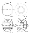
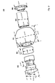
- Figs. 1a-c show an ornamental component 100 for a bracelet and / or a necklace having a through hole defining a through hole axis 104, according to an embodiment of the present invention.
- Fig. 1a shows a side view
- Fig. 1b shows a front view
- Fig. 1c shows a cross-section along the line A shown in Fig. 1b .
- the ornamental component 100 comprises a self-supporting housing 101 having a through hole 150 comprising a first opening at a first side of the self-supporting housing 151 and a second opening at a second side of the self-supporting housing 152, and an insert assembly 102 103 inserted in said through hole 150 of said self-supporting housing 101.
- the insert assembly 102 103 comprises a first tubular element 102 and a gripping element 103 (only schematically shown).
- the gripping element 103 is configured for frictionally gripping a part of a bracelet and / or necklace.
- the first tubular element 102 has a through hole 140 which in this embodiment forms the full through hole of the ornamental component 100.
- the through hole of the first tubular element 140 forms only a limited part of the through hole of the ornamental component 100.
- the through hole of the ornamental component allows it to be strung on an elongated member of a bracelet and / or necklace.
- the trough hole of the self-supporting housing 150 has a varying width (measured in planes being perpendicular to the through hole axis), i.e. the through hole of the self-supporting housing 150 is wider in the central part of self-supporting housing than at the first opening 151 and the second opening 152.
- the inner surface of the through hole of the self-supporting housing 150 is spaced apart from the insert assembly 102 103 by a fluid e.g. air.
- the first tubular element 102 is configured to secure said gripping element 103 inside the through hole 150 of said ornamental component. This may be achieved by attaching said gripping element 103 to the first tubular element 102 e.g.
- the first tubular element 102 may alternatively secure the gripping element 103 inside the through hole 150 of said ornamental component by having a part of the gripping element wrapped around its outer surface as disclosed in relation to Figs. 3-5 .
- Fig. 2 shows a cross-section of an ornamental component 200 for a bracelet and / or a necklace having a through hole defining a through hole axis 204 according to an embodiment of the present invention.
- the ornamental component 200 comprises a self-supporting housing 201 having a through hole 250 comprising a first opening at a first side of the self-supporting housing 251 and a second opening at a second side of the self-supporting housing 252, and an insert assembly 202 203 inserted in said through hole 250 of said self-supporting housing 201.
- the insert assembly 202 203 comprises a first tubular element 202 and a gripping element 203.
- the gripping element 203 is configured for frictionally gripping a part of a bracelet and / or necklace.
- the gripping element 203 has a tubular shape.
- the first tubular element 202 is configured to secure said gripping element 203 in said through hole of said ornamental component by having recess 290 in the central part of the inner wall of its through hole 240, where the gripping element 203 is positioned.
- the gripping element 203 may further be adhered to the inner wall of the first tubular element 202.
- the through hole of the first tubular element 240 forms the full through hole of the ornamental component 200.
- Fig. 3 shows an exploded view of an ornamental component 300 according to an embodiment of the present invention.
- the ornamental component 300 comprises an insert assembly 370, a second tubular element 305, a self-supporting housing 301, and a locking element 306.
- the insert assembly 370 comprises a first tubular element 302 and a gripping element 303. Shown is also the through hole axis 304.
- the first tubular element 302 has a through hole and comprises a collar 324, a first part 321, a second part 322, and a third part 323, as will be more detailed explained in relation to Figs. 4a-d .
- the locking element 306 has a through hole, and comprises an engagement part 361 for engaging with the insert assembly 370 and a collar 362 for being positioned outside the self-supporting housing 301.
- the ornamental component 300 may be manufactured / assembled by firstly assembling the insert assembly 370.
- the insert assembly 370 may be assembled by arranging the gripping element 303 around the second portion 322 of the first tubular element 302, so that gripping portions of the gripping element 303 (not shown) extends through circumferential openings of the first tubular element 302.
- the insert assembly 370 may be inserted into the second tubular element 305. Then the insert assembly 370 with the second tubular element may be inserted into a through hole of the self-supporting housing 350 in a manner so that the collar 324 is positioned outside the self-supporting housing 301.
- the second tubular element 305 may alternatively be inserted into the through hole of the self-supporting housing 350 before the insert assembly 370 is inserted.
- the insert assembly 370 and / or the second tubular element 305 may be inserted into the through hole of the self-supporting housing 350 through a first opening 351.
- the insert assembly 370 and / or the second tubular element 305 may alternatively be inserted into the through hole of the self-supporting housing 350 before the self-supporting housing 301 is fully formed / assembled e.g. the insert assembly 370 and / or the second tubular element may be inserted into a first half of the self supporting housing 301, whereafter a second half of the self-supporting housing 301 is attached to the first half, thereby forming the finished self-supporting housing 301 with the insert assembly 370 inserted in its through hole 350. Finally, the locking element 306 is inserted in a second opening 352 of the through hole of the self-supporting housing 350, and the engagement part 361 is attached to the first tubular element 302.
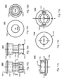
- Figs. 4a-d show a first tubular element comprising a through hole according to an embodiment of the present invention.
- the first tubular element shown in Fig. 4-d may correspond to the first tubular element 302 shown in Fig. 3 .
- Fig. 4a shows a side view
- Fig. 4b shows a cross-section along the line A
- Fig. 4c shows a front view
- Fig. 4d shows a back view.
- the first tubular element 402 comprises a through hole 474 defining a tubular element through hole axis 404.
- the first tubular element 402 comprises a first portion 421, a second portion 422, and a third portion 423.
- the width of the second portion 422 is lower than the widest width of the first potion 421 and the third portion 423.
- the first tubular element 402 further comprises a collar 424, a first circumferential opening 426, a second circumferential opening 427, and a third circumferential opening 428.
- Each of the circumferential openings 426 427 428 extends along the tubular element through hole axis 404.
- the circumferential openings 426 427 428 are spaced apart by walls 471 472 473 extending along to tubular element through hole axis 404.
- Each of the circumferential openings 426 427 428 extends B percentage of the circumference of the first tubular element. In the embodiment shown B is equal to 20.8%, i.e. 75 degrees. Correspondingly, each of the walls 471 472 473 extends C percentage of the circumference of the first tubular element. In the embodiment shown C is equal to 12.5%.
- the circumferential openings 426 427 428 are used to allow griping parts of the gripping element to extend through, into the through hole 474 of the first tubular element 402, thereby allowing the gripping parts to grip an elongated member of a bracelet and / or necklace.
- the collar 424 comprises a surface 474 for abutting an outer surface of a self-supporting housing for preventing the first tubular element 402 from moving in a first direction along the through hole axis relative to the self-supporting housing.
- the width of the through hole 474 is slightly extended in a part of the third portion 423, as illustrated by the broken line in Fig. 4a . This may allow an engagement portion of a locking element to be received, whereby a through hole of the locking element and the through hole 474 of the first tubular element 402 together can form a through hole of an ornamental component.
- the first tubular element 402 may optionally further comprise mechanical locking means 425 for mechanically attaching the first tubular element 402 with an engagement portion of a locking element e.g. a male / female locking mechanism.
- the first tubular element 402 has a length along the tubular element through hole axis 404 between 1 mm and 3 cm.
- Figs. 5a-b show a gripping element according to an embodiment of the present invention.
- Fig. 5a shows a side view
- Fig. 5b shows a front view.
- the gripping element 503 shown in Fig 5a-b may correspond to the gripping element 303 shown in Fig. 3 .
- the gripping element comprises a tubular portion 531 having an outer surface 532 and an inner surface 536.
- the gripping element 503 further comprises a first gripping portion 533, a second gripping portion 534, and a third gripping portion 535 protruding from the inner surface 536 of the tubular portion 531.
- Each of the gripping portions 533 534 535 protrudes from A percentage of the inner surface 536 of the tubular portion 531.
- A is equal to 19.4%, i.e. 70 degrees.
- the gripping portions 533 534 535 are used to resiliently grip an elongated member of a bracelet and / or necklace.
- the gripping element 503 may be made of a flexible material e.g. a silicone like material.
- the gripping element 503 may be attached with a first tubular element 402 as shown in Fig.
- the gripping element 503 may have a length C along the through hole axis, being approximately equal to the length of the circumferential openings of a first tubular element.
- Figs. 6a-b show a self-supporting housing according to an embodiment of the present invention.
- Fig. 6a shows a side view
- Fig. 6b shows a front view.
- the self-supporting housing 601 shown in Figs. 6a-b may correspond to the self-supporting housing 301 shown in Fig. 3 .
- the self-supporting housing 601 has a through hole 650 comprising a first opening at a first side of the self-supporting housing 651 and a second opening at a second side of the self-supporting housing 652.
- the trough hole of the self-supporting housing 650 has a varying width (measured in planes being perpendicular to the through hole axis), i.e.
- the self-supporting housing 601 comprises a planar surface 653 at the first opening 651 for abutting a surface of a collar of a first tubular element.
- the self supporting housing 601 comprises a planar surface 654 for abutting a surface of a collar of a locking element.
- Figs. 7a-b show a second tubular element according to an embodiment of the present invention.
- Fig. 7a shows a side view and
- Fig. 7b shows a front view.
- the second tubular element 705 shown in Figs. 7a-b may correspond to the second tubular element 305 shown in Fig. 3 .
- the second tubular element comprises a through hole 755, wherein a first tubular element with a gripping element attached may be positioned.
- Figs. 8a-b show a locking element according to an embodiment of the present invention.
- Fig. 8a shows a top view
- Fig. 8b shows a back view
- Fig. 8c shows a front view.
- the locking element 806 shown in Figs 8a-c may correspond to the locking element 306 shown in Fig. 3 .
- the locking element 806 comprises an engagement portion 861 for being attached with a part of a first tubular element, a collar for being positioned outside a self-supporting housing, and a through hole 865.
- the engagement portion 861 may optionally comprise mechanical locking means 864 for mechanically attaching the engagement portion 861 with a first tubular element 402 e.g. a male / female locking mechanism.
- the collar 862 comprises a planar surface 863 for abutting with a surface of a self-supporting housing.
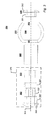
- Fig. 9 shows an exploded perspective view of an ornamental component with possible dimensions according to an embodiment of the present invention.
- the ornamental component 900 comprises a first tubular element 902, a gripping element 903, a self-supporting housing 901, a second tubular element 905, and a locking element 906.
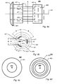
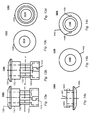
- Fig. 10a-d show a first tubular element according to an embodiment of the present invention.
- Fig. 10a shows a top view
- Fig. 10b shows a side view
- Fig. 10c shows a front view
- Fig. 10d shows a back view.
- the first tubular element 1002 has a through hole 1074 and comprises a collar 1024, a first portion 1021, a second portion 1022, and a third portion 1023.
- the collar 1024, the first portion 1021, and the second portion 1022 may be identical to the corresponding parts of the first tubular element shown in Fig. 4a-d .
- the third portion 1023 comprises mechanical locking means in the form of a female part of male / female locking mechanism 1075 1076.
- the female part 1075 1076 comprises a first opening 1075 and a second opening 1076 extending along the through hole axis.
- the first opening 1075 and the second opening 1076 are positioned opposite to each other.
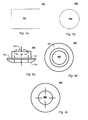
- Fig. 11a-d show a locking element 1106 according to an embodiment of the present invention.
- Fig. 11a shows a top view
- Fig. 11b shows a front view
- Fig. 11c shows a back view.
- the locking element 1106 has a through hole 1165 and comprises a collar 1162 and an engagement portion 1161.
- the collar 1162 may be identical to the collar of the locking element shown in
- the engagement portion 1161 comprises mechanical locking means in the form of the male part 1166 1167 of a male / female locking mechanism.
- the male part 1166 1167 comprises a first flexible member 1166 and a second flexible member 1167.
- the first and second flexible member 1166 1167 each comprises a protruding portion 1168 1169.
- the male / female locking mechanisms shown in Figs. 10a-c and Figs. 11a-c are configured to function together, thus the protruding portions 1168 1169 are configured to fit the openings 1075 1076.
- the locking element 1106 may be attached to the first tubular element 1002 by moving the two elements together until the male part comes into contact with the female part, whereby the first and second flexible member 1166 1167 are deformed from a first shape to a second shape, i.e. the first and second flexible member 1166 1167 are both progressively bent inwards. This is a result of an interaction between the rounded front surface of the two flexible members 1166 1167 and the rim 1077 of the through hole 1074 of the first tubular element 1002.
- the two flexible members 1166 1667 When the two flexible members 1166 1667 are aligned with the two openings 1075 1076 of the first tubular element 1002, the two flexible members 1166 1667 snap back into approximately the first shape, whereby the protruding portions of the two flexible members 1168 1669 engages with the openings 1075 1076 and locks the locking element 1106 to the first tubular element 1002.
- the locking element 1106 can be attached to the first tubular element 1002 by a pure translation between the two.
- the male / female locking mechanism 1075 1076 1166 1167 is of the snap lock type wherein a translation from a free position of the male and female part, to a locked position of the male and female part, requires less force than a translation from a locked position of the male and female part to a free position of the male and female part. This is a result of the special shape of the protruding potions 1168 1669 and the openings 1075 1076. This may be beneficial as the locking element 1106 and the first tubular element 1002 typically are permanently attached.
- Fig. 12 shows a central cross-section of a fully assembled ornamental component comprising a first tubular element and a locking element as disclosed in relation to Figs. 10a-d and Figs. 11a-c according to an embodiment of the present invention.
- the ornamental component 1200 comprises a self-supporting housing 1201, a first tubular element 1202, a gripping element 1203, a locking element 1206 and a second tubular element 1205.
- the ornamental component 1200 has a through hole 1250 defining a through hole axis 1204.
- the gripping element 1203 may be identical to the gripping element shown in Figs. 5a-b
- the self-supporting housing 1201 may be identical to the self-supporting housing shown in Figs.
- the second tubular element 1205 may be identical to the second tubular element shown in Figs. 7a-b . It can be seen how gripping portions of the gripping element 1203 protrudes into the through hole 1250 of the ornamental component 1200 allowing the gripping portions to frictionally grip an elongated member of an bracelet and / or necklace e.g. a chain of a bracelet and / or necklace.
- Fig. 13a-d show a first tubular element according to an embodiment of the present invention.
- Fig. 13a shows a top view
- Fig. 13b shows a side view
- Fig. 13c shows a front view
- Fig. 13d shows a back view.
- the first tubular element 1302 has a through hole 1374 and comprises a collar 1324, a first portion 1321, a second portion 1322, and a third portion 1323.
- the collar 1324, the first portion 1321, and the second portion 1322 may be identical to the corresponding parts of the first tubular element shown in Fig. 4a-d .
- the third portion 1323 comprises mechanical locking means in the form of a female part of male / female locking mechanism 1375 1376.
- the female part 1075 1076 comprises a first opening / or recess 1375 and a second opening or recess 1376.
- the first opening 1375 and the second opening 1376 are positioned opposite to each other.
- Fig. 14a-d show a locking element 1406 according to an embodiment of the present invention.
- Fig. 14a shows a top view
- Fig. 14b shows a front view
- Fig. 14c shows a back view.
- the locking element 1406 has a through hole 1465, and comprises a collar 1462 and an engagement portion 1461.
- the collar 1462 may be identical to the collar of the locking element shown in Fig. 8 .
- the engagement portion 1461 comprises mechanical locking means in the form of the male part 1468 1469 of a male / female locking mechanism.
- the male part 1468 1469 comprises a first protruding portion 1468 and a second protruding portion 1169.
- the locking element 1406 may be attached to the first tubular element 1302 by firstly rotationally orienting the locking element 1406 in a free rotational orientation relative to the first tubular element 1302(with the protruding portions 1468 1469 aligned with the openings 1375 1376), next translating the locking element 1406 along the through hole axis, and finally rotating the locking element 1406 from the free rotational orientation to a locked rotational orientation.
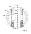
- Fig. 15 shows a central cross-section of a fully assembled ornamental component comprising a first tubular element and a locking element as disclosed in relation to Fig13a-d and Fig. 14a-c , according to an embodiment of the present invention.
- the ornamental component 1500 comprises a self-supporting housing 1501, a first tubular element 1502, a gripping element 1503, a locking element 1506, and a second tubular element 1505.
- the ornamental component 1500 has a through hole 1550 defining a through hole axis 1504.
- the gripping element 1503 may be identical to the gripping element shown in Fig. 5a-b
- the self-supporting housing 1501 may be identical to the self-supporting housing shown in Fig. 6a-b
- the second tubular element 1505 may be identical to the second tubular element shown in Fig. 7a-b .
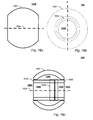
- Fig. 16a-c show an ornamental component according to an embodiment of the present invention.
- Fig. 16a shows a side view
- Fig. 16b shows a front view
- Fig. 16c shows a cross-section along the line A shown in Fig. 16b .
- the ornamental component 1600 is an ornamental component for use with a bracelet and / or necklace e.g. a bead.
- the ornamental component 1600 has a through hole 1698 allowing the ornamental component 1600 to be strung on an elongated member of a bracelet and / or necklace, the through hole 1698 defines a through hole axis 1604.
- the ornamental component 1600 comprises a self-supporting housing 1601, a first tubular element 1602, and a locking element 1606.
- the self-supporting housing 1601 has a through hole 1650 comprising a first opening 1651 at a first side of the housing, and a second opening 1652 at a second side of the housing.
- the first tubular element 1602 has a through hole 1640, and is inserted in the through hole of said self-supporting housing 1650 through the first opening of said self-supporting housing 1651.
- the locking element 1606 has a through hole 1655 and is inserted in the through hole of the self-supporting housing 1650 through the second opening of said self-supporting housing 1652.
- the locking element 1606 and the first tubular element 1602 are attached as schematically shown by the box 1699.
- the ornamental component 1600 may be a freely movable ornamental component or an ornamental component configured to resiliently grips an elongated member of a bracelet and / or necklace.
- Fig. 17a-b show an first tubular element for a freely movable ornamental component according to an embodiment of the present invention.
- Fig. 17a shows a top view and Fig. 17b shows a side view.
- the first tubular element 1702 has a through hole 1774.
- the first tubular element comprises a collar 1724 for being positioned outside a self-supporting housing, and mechanical locking means in the form of a female part of male / female locking mechanism 1775 1776.
- the female part 1775 1776 comprises a first opening 1775 and a second opening 1776 extending along the through hole axis.
- the first opening 1775 and the second opening 1776 are positioned opposite to each other.
- the male / female locking mechanism may be configured to function together with the male / female locking mechanism of the locking element 1106 shown in Fig. 11a-d i.e. the locking 1106 may be attached to the first tubular element 1702 by their respective male / female locking mechanisms.
- Fig. 18 shows a central cross-section of a fully assembled ornamental component configured to be freely movable, according to an embodiment of the present invention.
- the ornamental component 1800 comprises a self-supporting housing 1801, a first tubular element 1802, a locking element 1806, and a second tubular element 1505.
- the ornamental component 1800 has a through hole 1850 defining a through hole axis 1804.
- the second tubular element 1805 may be identical to the second tubular element shown in Fig. 7a-b .
- the first tubular element 1802 is a first tubular element as disclosed in relation to Figs. 17a-b
- the locking element 1806 is a locking element as disclosed in relation to Figs. 11a-c .
- the openings of the first tubular element 1802 and / or the openings of the locking element 1806 may optionally be pre-decorated e.g. comprise decorative engravings as schematically illustrated by the circles 1897.
Abstract
Description
- The present invention relates to an ornamental component for a bracelet or necklace, to a bracelet or necklace comprising such an ornamental component, to a method of manufacturing an ornamental component, and a tubular element for securing a gripping element inside a through hole of an ornamental component.
- Jewellery, such as necklaces and bracelets, often consists of a plurality of freely movable ornamental components e.g. beads strung on an elongated member e.g. chain, wire, or string. To prevent all the freely movable beads from grouping together at the bottom of the necklace or bracelet, an ornamental component provided with a stopping mechanism configured to grip the necklace or bracelet may be used. Such stopping mechanisms are known from the prior art in a variety of forms.
- An example of a prior art variation of a stopping mechanism is disclosed in
US 2003/0154742 , in which a jewel is produced with an elastic body inside configured to provide a frictional force on an elongated member. A similar solution is disclosed inUS 2002/0148250 , in which the jewel itself is provided with a flexible resilient tube with an inside diameter slightly smaller than the outer diameter of an elongated member, as to fix said jewel on said elongated member. - Another prior art variation is disclosed in
WO 2006/125155 . - It may, however, be difficult to produce such prior art ornamental components. Additionally, the stopping mechanisms may be vulnerable to damage.
- Thus, it remains a problem to provide a robust ornamental component provided with a stopping mechanism that can be easily manufactured.
- According to a first aspect, the invention relates to an ornamental component for a bracelet and / or a necklace, said ornamental component having a through hole allowing said ornamental component to be strung on an elongated member of a bracelet and / or necklace, said through hole defining a through hole axis; said ornamental component comprising:
- a self-supporting housing having a through hole comprising a first opening at a first side of the self-supporting housing and a second opening at a second side of the self-supporting housing; and
- an insert assembly inserted in said through hole of said self-supporting housing;
- Consequently, by using an insert assembly to provide an ornamental component with a gripping element, the production costs may be lowered. Additionally, by using a tubular element to secure the gripping element inside the self-supporting housing, the gripping element may be more efficiently protected from damage.
- An ornamental component may be any component that can be strung on a bracelet and / or necklace for ornamental purposes such as a bead. An ornamental component according to the first aspect of the invention may be used to organize freely movable beads on a bracelet or necklace, e.g. two ornamental components may be pulled to a desired position on an elongated member of a bracelet or necklace and released, whereby they resiliently grip the elongated member. Consequently, the bracelet or necklace is divided into three distinct zones for freely movable beads. This may be used to prevent all the freely movable beads from grouping together.
- The self-supporting housing may constitute the outer surface of the ornamental component or may be covered with another layer or element constituting the outer surface of the ornamental component. The self-supporting housing may have any shape such as approximately spherical, cylindrical or cubical. The self-supporting housing has a structural strength allowing it to be securely handled during the manufacturing process of the ornamental component. The self-supporting housing may provide the primary structural strength of the ornamental component. The self-supporting housing may be made of metal, glass, wood, plastic or a combination thereof. The trough hole of the self-supporting housing may have a constant width or may have a varying width (measured in planes being perpendicular to the through hole axis), e.g. the through hole of the self-supporting housing may be wider in the central part of self-supporting housing than at the first opening and the second opening. The inner surface of the through hole of the self-supporting housing may be spaced apart from the insert assembly by another element or a fluid e.g. air. At least a part of the self-supporting housing may be transparent or semi-transparent.
- The individual element of the insert assembly may be permanently attached or non-permanently attached. The insert assembly may be inserted into the through hole of the housing through the first opening of the housing, i.e. the insert assembly may have a size and shape allowing it to be insertable through the first opening of the self-supporting housing.
- The first tubular element may have any outer shape such as round or rectangular. Correspondingly, the through hole of the first tubular element may have any shape such as round or rectangular. The first tubular element may be integrally molded, i.e. made from a single mold. The first tubular element may be made of metal and / or plastic.
- The gripping element may be made of a material configured to establish a high frictional connection with an elongated member of a bracelet and / or necklace, e.g. a chain, band, or strand of a necklace or bracelet. The gripping element may be made of a deformable material such as a silicone material.
- In some embodiments, said gripping element is made of a first material and said first tubular element is made of a second material, wherein said coefficient of friction of said first material is higher than said coefficient of friction of said second material relative to sterling silver.
- The coefficient of friction of the first material may be at least 10%, 20%, 40% or 60% higher than the coefficient of friction of the second material relative to sterling silver.
- In some embodiments of the invention, the gripping element is positioned in a central part of the ornamental component and have a width along the through hole axis of less than 95%, 90%, 80%, 70%, 60% or 50% of the width of the self-supporting housing along the through hole axis.
- Consequently, the gripping element is better protected. Thus, a more robust ornamental component is provided.
- In some embodiments, said first tubular element comprises a first circumferential opening extending along the through hole axis, and wherein said gripping element comprises a first gripping portion for frictionally gripping said elongated member of said bracelet and / or necklace, wherein said first gripping part extends through said first circumferential opening.
- In some embodiments, said gripping element comprises a tubular portion, said first gripping portion protrudes from an interior surface of said tubular portion, and wherein said tubular portion of said gripping element surrounds a part of said first tubular element.
- Consequently, said tubular element may in an efficient manner secure said gripping element inside said through hole of said ornamental component.
- The entire gripping element may be integrally molded, i.e. made from a single mold.
- In some embodiments, said first tubular element comprises a second circumferential opening extending along the through hole axis and said gripping element comprises a second gripping portion protruding from an interior surface of said tubular portion of said gripping element, wherein said second gripping portion extends through said second circumferential opening.
- In some embodiments, said first tubular element comprises a third circumferential opening extending along the through hole axis and said gripping element comprises a third gripping portion protruding from an interior surface of said tubular potion of said gripping element, and wherein said third gripping portion extends through said third circumferential opening.
- In some embodiments, the first circumferential opening, the second circumferential opening and / or the third circumferential opening have a width along the through hole axis of less than 95%, 90%, 80%, 70%, 60% or 50% of the width of the first tubular element along the through hole axis.
- In some embodiments, each of the first circumferential opening, the second circumferential opening and / or the third circumferential opening extends between 5% and 33% of the circumference of the first tubular element in a plane being perpendicular to the through hole axis.
- In some embodiments, the first tubular element comprises a first portion and a second portion, wherein the second potion has a lower widest width than the widest width of the first portion, and wherein the tubular portion of the gripping element is arranged to fit snugly around the second portion of the first tubular element, and abutting the first portion of the first tubular element whereby the gripping element is prevented from moving in a first direction along the through hole axis relative to the first tubular element.
- In some embodiments, the first tubular element further comprises a third portion, and wherein the second potion has a lower widest width than the widest width of the first portion and the third portion, and wherein the tubular portion of the gripping element further abuts the third portion of the first tubular element thereby preventing the gripping element from moving in any direction along the through hole axis relative to the first tubular element.
- The widest width is measured in a plane being perpendicular to the through hole axis.
- In some embodiments, said tubular portion of said gripping element has a widest width approximately equal to the widest width of the first portion and /or third portion of the first tubular element.
- In some embodiments, the ornamental component further comprises a second tubular element, and wherein said first tubular element is positioned inside said second tubular element.
- This may make it easier to insert the insert assembly into the self-supporting housing. The second tubular element may additionally hide non-decorative elements of the ornamental component, when the self-supporting housing is transparent or semi-transparent.
- The second tubular element may have a width along the through hole axis being approximately equal to the width of the self-supporting housing. The second tubular element may be fully inserted into the through hole of the self-supporting housing.
- In some embodiments, said first tubular element of said insert assembly at a first end further comprises a collar, wherein said collar is positioned outside said self-supporting housing at the first opening of said self-supporting housing and comprises a surface abutting an outer surface of said self-supporting housing thereby preventing said first tubular element of said insert assembly from moving in a first direction along said through hole axis relative to said ornamental component.
- The outer surface may be an outer surface of said self-supporting housing. The collar may be an integral portion of the first tubular element or may be attached to the first tubular element.
- In some embodiments, said ornamental component further comprises a locking element having a through hole wherein said locking element comprises an engagement portion positioned inside said self-supporting housing and a collar positioned outside said self-supporting housing at the second opening of said self-supporting housing, wherein said engagement portion is attached to said first tubular element and said collar comprises a surface abutting an outer surface of said self-supporting housing thereby preventing said first tubular element of said insert assembly from moving in a second direction along said through hole axis relative to said ornamental component.
- Consequently, the insert assembly is in an effective manner secured to the self-supporting housing.
- The outer surface may be an outer surface of said self-supporting housing.
- The engagement portion and the collar of the locking element may be integrally formed. The locking element may be attached to the first tubular element by the use of glue or a mechanical locking mechanism.
- In some embodiments, said engagement part of said locking element is inserted into said first tubular element whereby said through hole of said locking element and said through hole of said first tubular element together forms the through hole of said ornamental component.
- In some embodiments, said engagement portion is attached to said first tubular element by a male / female locking mechanism, wherein the male part comprises a protruding portion and the female part comprises a recess and / or opening.
- The engagement portion may be the male part and the first tubular element may be the female part, i.e. the engagement portion may comprise a protruding portion configured to engage with recess and / or opening in the first tubular element. Alternatively, the first tubular element may be the male part and the engagement portion may be the female part.
- In some embodiments, the male / female locking mechanism is of the snap lock type wherein a translation and / or rotation from a free rotational orientation and / or position of the male and female part to a locked rotational orientation and / or position of the male and female part requires less force than a translation and / or rotation from a locked rotational orientation and / or position of the male and female part to a free rotational orientation and / or position of the male and female part.
- This may be beneficial as the locking element and the first tubular element typically are permanently attached.
- In some embodiments, the male / female locking mechanism may be of the rotational lock type, wherein the female part (the engagement portion or the first tubular element) comprises a recess and / or opening configured to allow the protruding portion of the male part to translate inside the recess and / or opening along the through hole axis when the locking element is in a free rotational orientation relative to the first tubular element, and to be prevented from moving in at least a first direction along the through hole axis when the locking element is in a locked position relative to the first tubular element and the locking element is in a locked rotational orientation relative to the first tubular element.
- In some embodiments, the male part comprises a plurality of protruding portions and the female part comprises a plurality of recess and / or openings.
- When the male / female locking mechanism is of the rotational type the locking element may be attached to the first tubular element by firstly rotationally orienting the locking element in the free rotational orientation relative to the first tubular element, next translating the first tubular element and / or the locking element along the through hole axis until the locking element is in the locked position relative to the first tubular element, and finally rotating the first tubular element and / or the locking element from the free rotational orientation to the locked rotational orientation.
- The protruding portion of the male part and / or the recess and / or opening of the female part may be configured so that a rotation from the free rotational orientation to the locked rotational orientation requires less force than a rotation from the locked rotational orientation to the free rotational orientation.
- In some embodiments, the male part (the engagement portion or the first tubular element) comprises a flexible member configured to deform from a first shape to a second shape when the male part comes into contact with the female part, and further to snap back into approximately the first shape when the flexible member is aligned with the recess and / or opening of the female part, whereby the flexible member engages with the recess and / or opening and locks the male part to the female part, allowing the locking element to be attached to the first tubular element by a pure translation between the two.
- In some embodiments, the male part comprises two flexible members, and the female part comprises two recesses and / or openings.
- The two flexible members may be arranged at opposite sides of the male part. Correspondingly, the two recesses and / or openings may be arranged at opposite sides of the female part.
- In some embodiments, the ornamental component has a length along the through hole axis between 2 mm and 5 cm.
- According to a second aspect, the invention relates to a bracelet or a necklace comprising:
- an elongated member; and
- a first ornamental component as disclosed in relation to the first aspect of the invention, strung on said elongated member;
- The elongated member may be any elongated member suitable for jewellery such as a metal chain, leather string, a fabric string, or an anchor type chain.
- In some embodiments, the particular force is higher than the maximum gravitational force gravity acting on the ornamental component.
- In some embodiments, the bracelet or necklace further comprises at least one freely movable ornamental component strung on said elongated member.
- In some embodiments, the bracelet or necklace further comprises a plurality of freely movable ornamental components strung on said elongated member.
- In some embodiments, the bracelet or necklace further comprises a second ornamental component as disclosed in relation to the first aspect of the invention strung on said elongated member; wherein the second ornamental component is configured so that the gripping element resiliently grips the elongated member to fix the second ornamental component along the elongated member until a particular force is acting on said second ornamental component, whereby the second ornamental component can be moved along the elongated member.
- According to a third aspect, the invention relates to a method for manufacturing an ornamental component, said ornamental component having a through hole allowing said ornamental component to be strung on an elongated member of a bracelet and / or necklace, said through hole defining a through hole axis, comprising the steps of:
- providing a self-supporting housing, having a through hole, wherein said through hole comprises a first opening at a first side of the self-supporting housing and a second opening at a second side of the self-supporting housing;
- assembling an insert assembly comprising a first tubular element having a through hole that at least partly forms said through hole of said ornamental component, and a gripping element for frictionally gripping said elongated member of a bracelet and / or a necklace; and
- inserting said insert assembly in said through hole of said housing.
- Consequently, an efficient method of producing an ornamental component comprising a gripping element is provided.
- In some embodiments, the insert assembly is inserted in said through hole of said self-supporting housing through said first opening of said self-supporting housing.
- In some embodiments, the ornamental component is an ornamental component as disclosed in relation to the first aspect of the invention.
- In some embodiments, said insert assembly is assembled before it is inserted into said through hole of said self-supporting housing.
- In some embodiments, said first tubular element comprises a first circumferential opening extending along the through hole axis, and wherein said gripping element comprises a first gripping portion, for frictionally gripping said elongated member of said bracelet and / or necklace, and a tubular portion, wherein said first gripping portion is protruding from an inner surface of said tubular portion, and wherein the step of assembling said insert assembly comprises pulling said gripping element around said first tubular element until said first gripping portion is aligned with said first circumferential opening, whereby said first gripping portion extends through said first circumferential opening and a part of said inner surface of said tubular portion rests upon a part of the outer surface of said first tubular element thereby securing said gripping element to said first tubular element.
- In some embodiments, said first tubular element further comprises a second circumferential opening extending along the through hole axis, and wherein said gripping element further comprises a second gripping portion for frictionally gripping said elongated member of said bracelet and / or necklace, wherein said second gripping portion is protruding from an inner surface of said tubular portion, and wherein the step of assembling said insert assembly comprises pulling said gripping element around said first tubular element until said first gripping portion is aligned with said firsts circumferential opening and said second gripping portion is aligned with said second circumferential opening, whereby said first gripping portion extends through said first circumferential opening, said second gripping portion extends through said second circumferential opening, and a part of said inner surface of said tubular portion rests upon a part of the outer surface of said first tubular element thereby attaching said gripping element to said first tubular element.
- In some embodiments, said first tubular element further comprises a third circumferential opening extending along the through hole axis, and wherein said gripping element further comprises a third gripping portion for frictionally gripping said elongated member of said bracelet and / or necklace, wherein said third gripping portion is protruding from an inner surface of said tubular portion, and wherein the step of assembling said insert assembly comprises pulling said gripping element around said first tubular element until said first gripping portion is aligned with said first circumferential opening, said second gripping portion is aligned with said second circumferential opening, and said third gripping portion is aligned with said third circumferential opening, whereby said first gripping portion extends through said first circumferential opening, said second gripping portion extends through said second circumferential opening, said third gripping portion extends through said third circumferential opening, and a part of said inner surface of said tubular portion rests upon a part of the outer surface of said first tubular element thereby attaching said gripping element to said first tubular element.
- In some embodiments, said ornamental component further comprises a locking element having a through hole, wherein said locking element comprises an engagement part for engaging with said insert assembly and a collar for being positioned outside said self-supporting housing, said method further comprising the step of:
- inserting said engagement part of said locking element into said second opening of said self-supporting housing, and
- attaching said engagement part to said insert assembly.
- In some embodiments, said engagement part is attached to said insert assembly by a male / female locking mechanism.
- According to a fourth aspect, the invention relates to a tubular element for securing a griping element, for gripping an elongated member of a bracelet and / necklace, in a through hole of an ornamental component, said tubular element having a through hole defining a tubular element through hole axis, wherein said tubular element comprises a first circumferential opening extending along the tubular element through hole axis for receiving a first gripping portion of said gripping element allowing said first gripping portion to extend through said first circumferential opening.
- In some embodiments, said tubular element further comprises a second circumferential opening extending along the tubular element through hole axis for receiving a second gripping portion of said gripping element allowing said second gripping portion to extend through said second circumferential opening.
- In some embodiments, said tubular element further comprises a third circumferential opening extending along the tubular element through hole axis for receiving a third gripping portion of said gripping element allowing said third gripping portion to extend through said third circumferential opening.
- In some embodiments, the first circumferential opening, the second circumferential opening and / or the third circumferential opening have a width along the tubular element through hole axis of less than 95%, 90%, 80%, 70%, 60% or 50% of the width of the tubular element along the tubular element through hole axis.
- In some embodiments, each of the first circumferential opening, the second circumferential opening and / or the third circumferential opening extends between 5% and 33% of the circumference of the tubular element in a plane being perpendicular to the tubular element through hole axis.
- In some embodiments, said tubular element is insertable in a through hole of a self-supporting housing of said ornamental component through a first opening of said through hole of said self-supporting housing.
- In some embodiments, the tubular element comprises a first portion and a second portion, wherein the first portion is positioned next to the second portion, the second potion has a lower widest width than the widest width of the first portion measured in a plane being perpendicular to the tubular element through hole axis, and wherein the first circumferential opening is positioned at the second portion of the tubular element.
- In some embodiments, the second circumferential opening is positioned at the second portion of the tubular element.
- In some embodiments, the third circumferential opening is positioned at the second portion of the tubular element.
- In some embodiments, the tubular element further comprises a third portion positioned next to the second portion, and wherein the second portion has a lower widest width than the widest width of the first portion and the third portion, measured in a plane being perpendicular to the tubular element through hole axis.
- In some embodiments, the first circumferential opening extends approximately the entire length, along the tubular element through hole axis, of the second portion of the tubular element.
- In some embodiments, the second circumferential opening extends approximately the entire length, along the tubular element through hole axis, of the second portion of the tubular element.
- In some embodiments, the third circumferential opening extends approximately the entire length, along the tubular element through hole axis, of the second portion of the tubular element.
- In some embodiments, said tubular element further comprises a collar for being positioned outside said self-supporting housing said collar comprising a surface for abutting an outer surface of said self-supporting housing for preventing said tubular element from moving in a first direction along said tubular element through hole axis relative to said self-supporting housing.
- The collar may be an integral portion of the first tubular element or may be attached to the first tubular element. The collar may be arranged at a first opening of the through hole of the tubular element.
- In some embodiments, said engagement portion is attached to said first tubular element by a male / female locking mechanism, wherein the male part comprises a protruding portion and the female part comprises a recess and / or opening.
- The engagement portion may be the male part and the first tubular element may be the female part, i.e. the engagement portion may comprise a protruding portion configured to engage with recess and / or opening in the first tubular element. Alternatively, the first tubular element may be the male part and the engagement portion may be the female part.
- In some embodiments, the male / female locking mechanism is of the snap lock type wherein a translation and / or rotation from a free rotational orientation and / or position of the male and female part to a locked rotational orientation and / or position of the male and female part requires less force than a translation and / or rotation from a locked rotational orientation and / or position of the male and female part to a free rotational orientation and / or position of the male and female part.
- This may be beneficial as the locking element and the first tubular element typically are permanently attached.
- In some embodiments, the male / female locking mechanism may be of the rotational lock type, wherein the female part (locking element or the tubular element) comprises a recess and / or opening configured to allow the protruding portion of the male part to translate inside the recess and / or opening along the tubular element through hole axis when the locking element is in a free rotational orientation relative to the first tubular element, and to be prevented from moving in at least a first direction along the tubular element through hole axis when the locking element is in a locked position relative to the first tubular element and the locking element is in a locked rotational orientation relative to the first tubular element.
- In some embodiments, the male part comprises a plurality of protruding portions and the female part comprises a plurality of recesses and / or openings.
- The protruding portion of the male part and / or the recess and / or opening of the female part may be configured so that a rotation from the free rotational orientation to the locked rotational orientation requires less force than a rotation from the locked rotational orientation to the free rotational orientation.
- In some embodiments, the tubular element has a length along the tubular element through hole axis between 2 mm and 3 cm.
- According to a fifth aspect, the invention relates to an ornamental component for a bracelet and / or a necklace said ornamental component having a through hole allowing said ornamental component to be strung on an elongated member of a bracelet and / or necklace, said through hole defining a through hole axis; said ornamental component comprising:
- a self-supporting housing having a through hole comprising a first opening at a first side of the housing and a second opening at a second side of the housing; and
- a first tubular element having a through hole inserted in said through hole of said self-supporting housing through said first opening of said self-supporting housing; and
- Consequently, by providing an ornamental component with a lining by using two parts inserted from two sides of the ornamental component, the lining (the first tubular element and the locking element) may be attached to the bead without deforming it. This allows more complex insert elements to be used such as pre decorated linings and lining composed of a plurality of elements.
- An ornamental component may be any component that can be strung on a bracelet and / or necklace for ornamental purposes such as a bead. An ornamental component according to the fifth aspect of the invention may be an freely movable ornamental component or an ornamental component used to organize freely movable beads on a bracelet or necklace The self-supporting housing may constitute the outer surface of the ornamental component or may be covered with another layer or element constituting the outer surface of the ornamental component. The self supporting housing may have any shape such as approximately spherical, cylindrical or cubical. The self-supporting housing has a structural strength allowing it to be securely handled during the manufacturing process of the ornamental component. The self-supporting housing may provide the primary structural strength of the ornamental component. The self-supporting housing may be made of metal, glass, wood, plastic or a combination thereof. The through hole of the self-supporting housing may have a constant width or may have a varying width (measured in planes being perpendicular to the through hole axis), e.g. the through hole of the self-supporting housing may be wider in the central part of self-supporting housing than at the first opening and the second opening. The inner surface of the through hole of the self-supporting housing may be spaced apart from the insert assembly by another element or a fluid e.g. air. At least a part of the self-supporting housing may be transparent or semi-transparent.
- The engagement portion and the first tubular element may be permanently attached or non-permanently attached.
- The first tubular element may have any outer shape such as round or rectangular. Correspondingly, the through hole of the first tubular element may have any shape such as round or rectangular. The first tubular element may be integrally molded, i.e. made from a single mold. The first tubular element may be made of metal and / or plastic.
- The engagement portion of the locking element may be attached to the first tubular element by the use of an adhesive or a mechanical locking mechanism.
- In some embodiments, said engagement portion is attached to said first tubular element by a male / female locking mechanism, wherein the male part comprises a protruding portion and the female part comprises a recess and / or opening.
- The engagement portion may be the male part and the first tubular element may be the female part, i.e. the engagement portion may comprise a protruding portion configured to engage with recess and / or opening in the first tubular element. Alternatively, the first tubular element may be the male part and the engagement portion may be the female part.
- In some embodiments, the ornamental component further comprises a second tubular element, and wherein said first tubular element and said engagement portion of said locking element is positioned inside said second tubular element.
- This may make it easier to insert the insert assembly into the self-supporting housing. The second tubular element may additionally hide non-decorative elements of the ornamental component, when the self-supporting housing is transparent or semi-transparent. The second tubular element may additionally protect the attachment between the first tubular element and the engagement portion.
- The second tubular element may have a length along the through hole axis being approximately equal to the length of the self-supporting housing. The second tubular element may be fully inserted into the through hole of the self-supporting housing. The engagement portion of the locking element may be fully inserted into the second tubular element.
- In some embodiments, the male / female locking mechanism is of the snap lock type wherein a translation and / or rotation from a free rotational orientation and / or position of the male and female part, to a locked rotational orientation and / or position of the male and female part, requires less force than a translation and / or rotation from a locked rotational orientation and / or position of the male and female part to a free rotational orientation and / or position of the male and female part.
- This may be beneficial as the locking element and the first tubular element typically are permanently attached.
- In some embodiments, the male / female locking mechanism is of the rotational lock type, wherein the female part (the engagement portion or the first tubular element) comprises a recess and / or opening configured to allow the protruding portion of the male part to translate inside the recess and / or opening along the through hole axis when the locking element is in a free rotational orientation relative to the first tubular element, and to be prevented from moving in at least a first direction along the through hole axis when the locking element is in a locked position relative to the first tubular element and the locking element is in a locked rotational orientation relative to the first tubular element.
- In some embodiments, the male part comprises a plurality of protruding portions and the female part comprises a plurality of recesses and / or openings.
- When the male / female locking mechanism is of the rotational type the locking element may be attached to the first tubular element by firstly rotationally orienting the locking element in the free rotational orientation relative to the first tubular element, next translating the first tubular element and / or the locking element along the through hole axis until the locking element is in the locked position relative to the first tubular element, and finally rotating the first tubular element and / or the locking element from the free rotational orientation to the locked rotational orientation.
- The protruding portion of the male part and / or the recess and / or opening of the female part may be configured so that a rotation from the free rotational orientation to the locked rotational orientation requires less force than a rotation from the locked rotational orientation to the free rotational orientation.
- In some embodiments, the male part (the engagement portion or the first tubular element) comprises a flexible member configured to deform from a first shape to a second shape when the male part comes into contact with the female part, and further to snap back into approximately the first shape when the flexible member is aligned with the recess and / or opening of the female part, whereby the flexible member engages with the recess and / or opening and locks the male part to the female part, allowing the locking element to be attached to the first tubular element by a pure translation between the two.
- In some embodiments, the male part comprises two flexible members, and the female part comprises two recesses and / or openings.
- The two flexible members may be arranged at opposite sides of the male part. Correspondingly, the two recesses and / or openings may be arranged at opposite sides of the female part.
- In some embodiments, said engagement part of said locking element is inserted into said first tubular element whereby said through hole of said locking element and said through hole of said first tubular element together forms the through hole of said ornamental component.
- In some embodiments, said first tubular element at a first end further comprises a collar, wherein said collar is positioned outside said self-supporting housing at the first opening of said self-supporting housing and comprises a surface abutting an outer surface of said self-supporting housing thereby preventing said first tubular element from moving in a first direction along said through hole axis relative to said ornamental component.
- In some embodiments, said locking element further comprises a collar positioned outside said self-supporting housing at the second opening of said self-supporting housing, said collar comprising a surface abutting an outer surface of said self-supporting housing thereby preventing said first tubular element from moving in a second direction along said through hole axis relative to said ornamental component.
- In some embodiments, the first tubular element is part of an insert assembly inserted in said through hole of said self-supporting housing through said first opening of said self-supporting housing, wherein said insert assembly is assembled from said first tubular element and a gripping element for frictionally gripping a part of said bracelet and / or necklace; wherein said first tubular element is configured to secure said gripping element inside said through hole of said ornamental component.
- According to a sixth aspect, the invention relates to a method for manufacturing an ornamental component, said ornamental component having a through hole allowing said ornamental component to be strung on an elongated member of a bracelet and / or necklace, said through hole defining a through hole axis, the method comprising the steps of:
- providing a self-supporting housing, having an through hole, wherein said through hole comprises a first opening at a first side of the self-supporting housing and a second opening at a second side of the self-supporting housing;
- inserting through said first opening of said self-supporting housing a first tubular element having a through hole;
- inserting through said second opening of said self-supporting housing a locking element having a through hole, said locking element comprising an engagement portion for being positioned inside said through hole of said self-supporting housing; and
- attaching said engagement portion of said locking element to said first tubular element.
- Consequently, by using two parts inserted from two sides of the ornamental component, the lining (the first tubular element and the locking element) may be attached to the bead without deforming it. This allows more complex insert elements to be used such as pre decorated linings and linings composed of a plurality of elements.
- In some embodiments, the engagement portion is attached to said tubular element by a by a male / female locking mechanism.
- In some embodiments, the method further comprises the step of inserting a second tubular element into the through hole of the self-supporting housing, either through said first opening or said second opening of said self-supporting housing, wherein said first tubular element and said engagement portion of said locking element is inserted into said second tubular element.
- In some embodiments, the ornamental component is an ornamental component as disclosed in relation to the fifth aspect of the invention.
- The different aspects of the present invention can be implemented in different ways including as ornamental components, bracelets or necklaces comprising ornamental components, tubular elements for ornamental components, and methods for manufacturing ornamental components described above and in the following, each yielding one or more of the benefits and advantages described in connection with at least one of the aspects described above, and each having one or more preferred embodiments corresponding to the preferred embodiments described in connection with at least one of the aspects described above and / or disclosed in the dependant claims.
- Furthermore, it will be appreciated that embodiments described in connection with one of the aspects described herein may equally be applied to the other aspects. Aspects of the first tubular element disclosed in relation to the first aspect of the invention may be applied to the tubular element disclosed in relation to the fourth aspect of the invention and vice versa. Similarly, aspects disclosed in relation to the ornamental component disclosed in relation to the first aspect of the invention may be applied to the method disclosed in relation to the third aspect of the invention and vice versa. Further aspects disclosed in relation to the ornamental component disclosed in relation to the fifth aspect of the invention may be applied to the method disclosed in relation to the sixth aspect of the invention and vice versa.
- The above and / or additional objects, features and advantages of the present invention will be further elucidated by the following illustrative and non-limiting detailed description of embodiments of the present invention, with reference to the appended drawings, wherein:
-
Figs. 1a-c show an ornamental component according to an embodiment of the present invention. -
Fig. 2 shows an ornamental component according to an embodiment of the present invention. -
Fig. 3 shows an ornamental component according to an embodiment of the present invention. -
Figs. 4a-d show a first tubular element according to an embodiment of the present invention. -
Fig. 5a-b show a gripping element according to an embodiment of the present invention. -
Fig. 6a-b show a self-supporting housing according to an embodiment of the present invention. -
Fig. 7a-b show a second tubular element according to an embodiment of the present invention. -
Fig. 8a-c show a locking element according to an embodiment of the present invention. -
Fig. 9 shows an ornamental component according to an embodiment of the present invention. -
Figs. 10a-d show a first tubular element according to an embodiment of the present invention. -
Fig. 11a-c show a locking element according to an embodiment of the present invention. -
Fig. 12 shows an ornamental component according to an embodiment of the present invention. -
Figs. 13a-d show a first tubular element according to an embodiment of the present invention. -
Fig. 14a-c show a locking element according to an embodiment of the present invention. -
Fig. 15 shows an ornamental component according to an embodiment of the present invention. -
Fig. 16 a-c show an ornamental component according to an embodiment of the present invention. -
Figs. 17a-b show a first tubular element according to an embodiment of the present invention. -
Fig. 18 shows an ornamental component according to an embodiment of the present invention. - In the following description, reference is made to the accompanying figures, which show by way of illustration how the invention may be practiced.
-
Figs. 1a-c show anornamental component 100 for a bracelet and / or a necklace having a through hole defining a throughhole axis 104, according to an embodiment of the present invention.Fig. 1a shows a side view,Fig. 1b shows a front view, andFig. 1c shows a cross-section along the line A shown inFig. 1b . Theornamental component 100 comprises a self-supportinghousing 101 having a throughhole 150 comprising a first opening at a first side of the self-supportinghousing 151 and a second opening at a second side of the self-supportinghousing 152, and aninsert assembly 102 103 inserted in said throughhole 150 of said self-supportinghousing 101. Theinsert assembly 102 103 comprises a firsttubular element 102 and a gripping element 103 (only schematically shown). Thegripping element 103 is configured for frictionally gripping a part of a bracelet and / or necklace. The firsttubular element 102 has a throughhole 140 which in this embodiment forms the full through hole of theornamental component 100. However, in other embodiments of the invention the through hole of the firsttubular element 140 forms only a limited part of the through hole of theornamental component 100. The through hole of the ornamental component allows it to be strung on an elongated member of a bracelet and / or necklace. The trough hole of the self-supportinghousing 150 has a varying width (measured in planes being perpendicular to the through hole axis), i.e. the through hole of the self-supportinghousing 150 is wider in the central part of self-supporting housing than at thefirst opening 151 and thesecond opening 152. The inner surface of the through hole of the self-supportinghousing 150 is spaced apart from theinsert assembly 102 103 by a fluid e.g. air. The firsttubular element 102 is configured to secure saidgripping element 103 inside the throughhole 150 of said ornamental component. This may be achieved by attaching saidgripping element 103 to the firsttubular element 102 e.g. by adhering the two elements together or by positioning thegripping element 103 in a recess of the firsttubular element 102 e.g. as shown inFig. 2 . The firsttubular element 102 may alternatively secure thegripping element 103 inside the throughhole 150 of said ornamental component by having a part of the gripping element wrapped around its outer surface as disclosed in relation toFigs. 3-5 . -
Fig. 2 shows a cross-section of anornamental component 200 for a bracelet and / or a necklace having a through hole defining a throughhole axis 204 according to an embodiment of the present invention. Theornamental component 200 comprises a self-supportinghousing 201 having a throughhole 250 comprising a first opening at a first side of the self-supportinghousing 251 and a second opening at a second side of the self-supportinghousing 252, and aninsert assembly 202 203 inserted in said throughhole 250 of said self-supportinghousing 201. Theinsert assembly 202 203 comprises a firsttubular element 202 and agripping element 203. Thegripping element 203 is configured for frictionally gripping a part of a bracelet and / or necklace. Thegripping element 203 has a tubular shape. The firsttubular element 202 is configured to secure saidgripping element 203 in said through hole of said ornamental component by havingrecess 290 in the central part of the inner wall of its throughhole 240, where thegripping element 203 is positioned. Optionally, thegripping element 203 may further be adhered to the inner wall of the firsttubular element 202. The through hole of the firsttubular element 240 forms the full through hole of theornamental component 200. -
Fig. 3 shows an exploded view of anornamental component 300 according to an embodiment of the present invention. Theornamental component 300 comprises aninsert assembly 370, a secondtubular element 305, a self-supportinghousing 301, and alocking element 306. Theinsert assembly 370 comprises a firsttubular element 302 and agripping element 303. Shown is also the throughhole axis 304. The firsttubular element 302 has a through hole and comprises acollar 324, afirst part 321, asecond part 322, and athird part 323, as will be more detailed explained in relation toFigs. 4a-d . The lockingelement 306 has a through hole, and comprises anengagement part 361 for engaging with theinsert assembly 370 and acollar 362 for being positioned outside the self-supportinghousing 301. Theornamental component 300 may be manufactured / assembled by firstly assembling theinsert assembly 370. Theinsert assembly 370 may be assembled by arranging thegripping element 303 around thesecond portion 322 of the firsttubular element 302, so that gripping portions of the gripping element 303 (not shown) extends through circumferential openings of the firsttubular element 302. Next, theinsert assembly 370 may be inserted into the second tubular element 305.Then theinsert assembly 370 with the second tubular element may be inserted into a through hole of the self-supportinghousing 350 in a manner so that thecollar 324 is positioned outside the self-supportinghousing 301. The secondtubular element 305 may alternatively be inserted into the through hole of the self-supportinghousing 350 before theinsert assembly 370 is inserted. Theinsert assembly 370 and / or the secondtubular element 305 may be inserted into the through hole of the self-supportinghousing 350 through afirst opening 351. Theinsert assembly 370 and / or the secondtubular element 305 may alternatively be inserted into the through hole of the self-supportinghousing 350 before the self-supportinghousing 301 is fully formed / assembled e.g. theinsert assembly 370 and / or the second tubular element may be inserted into a first half of theself supporting housing 301, whereafter a second half of the self-supportinghousing 301 is attached to the first half, thereby forming the finished self-supportinghousing 301 with theinsert assembly 370 inserted in its throughhole 350. Finally, the lockingelement 306 is inserted in asecond opening 352 of the through hole of the self-supportinghousing 350, and theengagement part 361 is attached to the firsttubular element 302. -
Figs. 4a-d show a first tubular element comprising a through hole according to an embodiment of the present invention. The first tubular element shown inFig. 4-d may correspond to the firsttubular element 302 shown inFig. 3 .Fig. 4a shows a side view,Fig. 4b shows a cross-section along the line A,Fig. 4c shows a front view, andFig. 4d shows a back view. The firsttubular element 402 comprises a throughhole 474 defining a tubular element throughhole axis 404. When the firsttubular element 402 is positioned in a ornamental component according the invention, the tubular element throughhole axis 404 and the ornamental component through hole axis will be coincident. The firsttubular element 402 comprises afirst portion 421, asecond portion 422, and athird portion 423. The width of thesecond portion 422 is lower than the widest width of thefirst potion 421 and thethird portion 423. The firsttubular element 402 further comprises acollar 424, a firstcircumferential opening 426, a secondcircumferential opening 427, and a thirdcircumferential opening 428. Each of thecircumferential openings 426 427 428 extends along the tubular element throughhole axis 404. Thecircumferential openings 426 427 428 are spaced apart bywalls 471 472 473 extending along to tubular element throughhole axis 404. Each of thecircumferential openings 426 427 428 extends B percentage of the circumference of the first tubular element. In the embodiment shown B is equal to 20.8%, i.e. 75 degrees. Correspondingly, each of thewalls 471 472 473 extends C percentage of the circumference of the first tubular element. In the embodiment shown C is equal to 12.5%. Thecircumferential openings 426 427 428 are used to allow griping parts of the gripping element to extend through, into the throughhole 474 of the firsttubular element 402, thereby allowing the gripping parts to grip an elongated member of a bracelet and / or necklace. Thecollar 424 comprises asurface 474 for abutting an outer surface of a self-supporting housing for preventing the firsttubular element 402 from moving in a first direction along the through hole axis relative to the self-supporting housing. The width of the throughhole 474 is slightly extended in a part of thethird portion 423, as illustrated by the broken line inFig. 4a . This may allow an engagement portion of a locking element to be received, whereby a through hole of the locking element and the throughhole 474 of the firsttubular element 402 together can form a through hole of an ornamental component. The firsttubular element 402 may optionally further comprise mechanical locking means 425 for mechanically attaching the firsttubular element 402 with an engagement portion of a locking element e.g. a male / female locking mechanism. In some embodiments, the firsttubular element 402 has a length along the tubular element throughhole axis 404 between 1 mm and 3 cm. -
Figs. 5a-b show a gripping element according to an embodiment of the present invention.Fig. 5a shows a side view, andFig. 5b shows a front view. Thegripping element 503 shown inFig 5a-b may correspond to thegripping element 303 shown inFig. 3 . The gripping element comprises atubular portion 531 having anouter surface 532 and aninner surface 536. Thegripping element 503 further comprises a firstgripping portion 533, a secondgripping portion 534, and a thirdgripping portion 535 protruding from theinner surface 536 of thetubular portion 531. Each of thegripping portions 533 534 535 protrudes from A percentage of theinner surface 536 of thetubular portion 531. In the embodiment shown A is equal to 19.4%, i.e. 70 degrees. The grippingportions 533 534 535 are used to resiliently grip an elongated member of a bracelet and / or necklace. Thegripping element 503 may be made of a flexible material e.g. a silicone like material. Thegripping element 503 may be attached with a firsttubular element 402 as shown inFig. 4a-d by pulling thegripping element 503 around the firsttubular element 402 until the firstgripping portion 533 is aligned with the firstcircumferential opening 426, the secondgripping portion 534 is aligned with the secondcircumferential opening 427, and the thirdgripping portion 535 is aligned with the thirdcircumferential opening 428, whereby the firstgripping portion 533 extends through the firstcircumferential opening 426, the secondgripping portion 534 extends through the secondcircumferential opening 427, the thirdgripping portion 535 extends through the thirdcircumferential opening 428, and a part of theinner surface 536 of thetubular portion 531 rests upon a part of theouter surface 471 472 473 of the firsttubular element 402 thereby attaching thegripping element 503 to the first tubular element 502. - The
gripping element 503 may have a length C along the through hole axis, being approximately equal to the length of the circumferential openings of a first tubular element. -
Figs. 6a-b show a self-supporting housing according to an embodiment of the present invention.Fig. 6a shows a side view andFig. 6b shows a front view. The self-supportinghousing 601 shown inFigs. 6a-b may correspond to the self-supportinghousing 301 shown inFig. 3 . The self-supportinghousing 601 has a throughhole 650 comprising a first opening at a first side of the self-supportinghousing 651 and a second opening at a second side of the self-supporting housing 652. The trough hole of the self-supportinghousing 650 has a varying width (measured in planes being perpendicular to the through hole axis), i.e. the through hole of the self-supportinghousing 650 is wider in the central part of self-supporting housing than at thefirst opening 651 and the second opening 652. The self-supportinghousing 601 comprises aplanar surface 653 at thefirst opening 651 for abutting a surface of a collar of a first tubular element. Correspondingly, theself supporting housing 601 comprises aplanar surface 654 for abutting a surface of a collar of a locking element. -
Figs. 7a-b show a second tubular element according to an embodiment of the present invention.Fig. 7a shows a side view andFig. 7b shows a front view. The secondtubular element 705 shown inFigs. 7a-b may correspond to the secondtubular element 305 shown inFig. 3 . The second tubular element comprises a throughhole 755, wherein a first tubular element with a gripping element attached may be positioned. -
Figs. 8a-b show a locking element according to an embodiment of the present invention.Fig. 8a shows a top view,Fig. 8b shows a back view andFig. 8c shows a front view. The lockingelement 806 shown inFigs 8a-c may correspond to thelocking element 306 shown inFig. 3 . The lockingelement 806 comprises anengagement portion 861 for being attached with a part of a first tubular element, a collar for being positioned outside a self-supporting housing, and a throughhole 865. Theengagement portion 861 may optionally comprise mechanical locking means 864 for mechanically attaching theengagement portion 861 with a firsttubular element 402 e.g. a male / female locking mechanism. Thecollar 862 comprises aplanar surface 863 for abutting with a surface of a self-supporting housing. -
Fig. 9 shows an exploded perspective view of an ornamental component with possible dimensions according to an embodiment of the present invention. Theornamental component 900 comprises a firsttubular element 902, agripping element 903, a self-supportinghousing 901, a secondtubular element 905, and alocking element 906. -
Fig. 10a-d show a first tubular element according to an embodiment of the present invention.Fig. 10a shows a top view,Fig. 10b shows a side view,Fig. 10c shows a front view andFig. 10d shows a back view. The firsttubular element 1002 has a throughhole 1074 and comprises acollar 1024, afirst portion 1021, asecond portion 1022, and athird portion 1023. Thecollar 1024, thefirst portion 1021, and thesecond portion 1022 may be identical to the corresponding parts of the first tubular element shown inFig. 4a-d . Thethird portion 1023 comprises mechanical locking means in the form of a female part of male /female locking mechanism 1075 1076. Thefemale part 1075 1076 comprises afirst opening 1075 and asecond opening 1076 extending along the through hole axis. Thefirst opening 1075 and thesecond opening 1076 are positioned opposite to each other. -
Fig. 11a-d show alocking element 1106 according to an embodiment of the present invention.Fig. 11a shows a top view,Fig. 11b shows a front view andFig. 11c shows a back view. Thelocking element 1106 has a throughhole 1165 and comprises acollar 1162 and anengagement portion 1161. Thecollar 1162 may be identical to the collar of the locking element shown in -
Fig. 8 . Theengagement portion 1161 comprises mechanical locking means in the form of themale part 1166 1167 of a male / female locking mechanism. Themale part 1166 1167 comprises a firstflexible member 1166 and a secondflexible member 1167. The first and secondflexible member 1166 1167 each comprises a protrudingportion 1168 1169. The male / female locking mechanisms shown inFigs. 10a-c and Figs. 11a-c are configured to function together, thus the protrudingportions 1168 1169 are configured to fit theopenings 1075 1076. Thelocking element 1106 may be attached to the firsttubular element 1002 by moving the two elements together until the male part comes into contact with the female part, whereby the first and secondflexible member 1166 1167 are deformed from a first shape to a second shape, i.e. the first and secondflexible member 1166 1167 are both progressively bent inwards. This is a result of an interaction between the rounded front surface of the twoflexible members 1166 1167 and therim 1077 of the throughhole 1074 of the firsttubular element 1002. When the twoflexible members 1166 1667 are aligned with the twoopenings 1075 1076 of the firsttubular element 1002, the twoflexible members 1166 1667 snap back into approximately the first shape, whereby the protruding portions of the twoflexible members 1168 1669 engages with theopenings 1075 1076 and locks thelocking element 1106 to the firsttubular element 1002. Thus, thelocking element 1106 can be attached to the firsttubular element 1002 by a pure translation between the two. The male /female locking mechanism 1075 1076 1166 1167 is of the snap lock type wherein a translation from a free position of the male and female part, to a locked position of the male and female part, requires less force than a translation from a locked position of the male and female part to a free position of the male and female part. This is a result of the special shape of the protrudingpotions 1168 1669 and theopenings 1075 1076. This may be beneficial as thelocking element 1106 and the firsttubular element 1002 typically are permanently attached. -
Fig. 12 shows a central cross-section of a fully assembled ornamental component comprising a first tubular element and a locking element as disclosed in relation toFigs. 10a-d and Figs. 11a-c according to an embodiment of the present invention. Theornamental component 1200 comprises a self-supportinghousing 1201, a firsttubular element 1202, agripping element 1203, alocking element 1206 and a secondtubular element 1205. Theornamental component 1200 has a throughhole 1250 defining a throughhole axis 1204. Thegripping element 1203 may be identical to the gripping element shown inFigs. 5a-b , the self-supportinghousing 1201 may be identical to the self-supporting housing shown inFigs. 6a-b , and the secondtubular element 1205 may be identical to the second tubular element shown inFigs. 7a-b . It can be seen how gripping portions of thegripping element 1203 protrudes into the throughhole 1250 of theornamental component 1200 allowing the gripping portions to frictionally grip an elongated member of an bracelet and / or necklace e.g. a chain of a bracelet and / or necklace. -
Fig. 13a-d show a first tubular element according to an embodiment of the present invention.Fig. 13a shows a top view,Fig. 13b shows a side view,Fig. 13c shows a front view, andFig. 13d shows a back view. The firsttubular element 1302 has a throughhole 1374 and comprises acollar 1324, afirst portion 1321, asecond portion 1322, and athird portion 1323. Thecollar 1324, thefirst portion 1321, and thesecond portion 1322 may be identical to the corresponding parts of the first tubular element shown inFig. 4a-d . Thethird portion 1323 comprises mechanical locking means in the form of a female part of male /female locking mechanism 1375 1376. Thefemale part 1075 1076 comprises a first opening / orrecess 1375 and a second opening orrecess 1376. Thefirst opening 1375 and thesecond opening 1376 are positioned opposite to each other. -
Fig. 14a-d show alocking element 1406 according to an embodiment of the present invention.Fig. 14a shows a top view,Fig. 14b shows a front view, andFig. 14c shows a back view. Thelocking element 1406 has a throughhole 1465, and comprises acollar 1462 and anengagement portion 1461. Thecollar 1462 may be identical to the collar of the locking element shown inFig. 8 . Theengagement portion 1461 comprises mechanical locking means in the form of themale part 1468 1469 of a male / female locking mechanism. Themale part 1468 1469 comprises a first protrudingportion 1468 and asecond protruding portion 1169. The male / female locking mechanisms shown inFig. 13a-c and Fig. 114-c are configured to function together, thus the protrudingportions 1468 1469 are configured to fit theopenings 1375 1376. The male / female locking mechanism is of the rotational type. Thelocking element 1406 may be attached to the firsttubular element 1302 by firstly rotationally orienting thelocking element 1406 in a free rotational orientation relative to the first tubular element 1302(with the protrudingportions 1468 1469 aligned with theopenings 1375 1376), next translating thelocking element 1406 along the through hole axis, and finally rotating thelocking element 1406 from the free rotational orientation to a locked rotational orientation. -
Fig. 15 shows a central cross-section of a fully assembled ornamental component comprising a first tubular element and a locking element as disclosed in relation toFig13a-d andFig. 14a-c , according to an embodiment of the present invention. The ornamental component 1500 comprises a self-supportinghousing 1501, a firsttubular element 1502, agripping element 1503, a locking element 1506, and a second tubular element 1505. The ornamental component 1500 has a throughhole 1550 defining a throughhole axis 1504. Thegripping element 1503 may be identical to the gripping element shown inFig. 5a-b , the self-supportinghousing 1501 may be identical to the self-supporting housing shown inFig. 6a-b , and the second tubular element 1505 may be identical to the second tubular element shown inFig. 7a-b . -
Fig. 16a-c show an ornamental component according to an embodiment of the present invention.Fig. 16a shows a side view,Fig. 16b shows a front view, andFig. 16c shows a cross-section along the line A shown inFig. 16b . Theornamental component 1600 is an ornamental component for use with a bracelet and / or necklace e.g. a bead. Theornamental component 1600 has a throughhole 1698 allowing theornamental component 1600 to be strung on an elongated member of a bracelet and / or necklace, the throughhole 1698 defines a throughhole axis 1604. Theornamental component 1600 comprises a self-supportinghousing 1601, a firsttubular element 1602, and alocking element 1606. The self-supportinghousing 1601 has a throughhole 1650 comprising afirst opening 1651 at a first side of the housing, and asecond opening 1652 at a second side of the housing. The firsttubular element 1602 has a throughhole 1640, and is inserted in the through hole of said self-supportinghousing 1650 through the first opening of said self-supportinghousing 1651. Thelocking element 1606 has a through hole 1655 and is inserted in the through hole of the self-supportinghousing 1650 through the second opening of said self-supportinghousing 1652. Thelocking element 1606 and the firsttubular element 1602 are attached as schematically shown by thebox 1699. The through hole of the firsttubular element 1640 and the through hole of thelocking element 1665 together form the through hole of theornamental component 1698. Theornamental component 1600 may be a freely movable ornamental component or an ornamental component configured to resiliently grips an elongated member of a bracelet and / or necklace. -
Fig. 17a-b show an first tubular element for a freely movable ornamental component according to an embodiment of the present invention.Fig. 17a shows a top view andFig. 17b shows a side view. The firsttubular element 1702 has a throughhole 1774. The first tubular element comprises acollar 1724 for being positioned outside a self-supporting housing, and mechanical locking means in the form of a female part of male /female locking mechanism 1775 1776. Thefemale part 1775 1776 comprises afirst opening 1775 and asecond opening 1776 extending along the through hole axis. Thefirst opening 1775 and thesecond opening 1776 are positioned opposite to each other. The male / female locking mechanism may be configured to function together with the male / female locking mechanism of thelocking element 1106 shown inFig. 11a-d i.e. the locking 1106 may be attached to the firsttubular element 1702 by their respective male / female locking mechanisms. -
Fig. 18 shows a central cross-section of a fully assembled ornamental component configured to be freely movable, according to an embodiment of the present invention. Theornamental component 1800 comprises a self-supportinghousing 1801, a firsttubular element 1802, alocking element 1806, and a second tubular element 1505. Theornamental component 1800 has a throughhole 1850 defining a throughhole axis 1804. The secondtubular element 1805 may be identical to the second tubular element shown inFig. 7a-b . The firsttubular element 1802 is a first tubular element as disclosed in relation toFigs. 17a-b , and thelocking element 1806 is a locking element as disclosed in relation toFigs. 11a-c . The openings of the firsttubular element 1802 and / or the openings of thelocking element 1806 may optionally be pre-decorated e.g. comprise decorative engravings as schematically illustrated by thecircles 1897. - Although some embodiments have been described and shown in detail, the invention is not restricted to them, but may also be embodied in other ways within the scope of the subject matter defined in the following claims. In particular, it is to be understood that other embodiments may be utilised and structural and functional modifications may be made without departing from the scope of the present invention.
- In device claims enumerating several means, several of these means can be embodied by one and the same item of hardware. The mere fact that certain measures are recited in mutually different dependent claims or described in different embodiments does not indicate that a combination of these measures cannot be used to advantage.
- It should be emphasized that the term "comprises/comprising" when used in this specification is taken to specify the presence of stated features, integers, steps or components but does not preclude the presence or addition of one or more other features, integers, steps, components or groups thereof.
Claims (15)
- An ornamental component (100) for a bracelet and / or a necklace, said ornamental component (100) having a through hole (140) allowing said ornamental component (100) to be strung on an elongated member of a bracelet and / or necklace, said through hole defining a through hole axis (104); said ornamental component comprising:• a self-supporting housing (101) having a through hole (150) comprising a first opening at a first side of the self-supporting housing (151) and a second opening at a second side of the self-supporting housing (152); and• an insert assembly (102, 103) inserted in said through hole of said self-supporting housing;wherein said insert assembly (102, 103) is assembled from a first tubular element (102) having a through hole (140) that forms at least a part of said through hole of said ornamental component and a gripping element (103) for frictionally gripping a part of said bracelet and / or necklace; wherein said first tubular element (102) is configured to secure said gripping element (103) inside said through hole of said ornamental component.
- An ornamental component according to claim 1, wherein the insert assembly is inserted into the through hole of the self-supporting housing through the first opening of the self-supporting housing.
- An ornamental component according to claim 1 or 2, wherein said first tubular element comprises a first circumferential opening extending along the through hole axis, and wherein said gripping element comprises a first gripping portion for frictionally gripping said elongated member of said bracelet and / or necklace, wherein said first gripping part extends through said first circumferential opening.
- An ornamental component according to claim 3, wherein said gripping element comprises a tubular portion, said first gripping portion protrudes from an interior surface of said tubular portion, and wherein said tubular portion of said gripping element surrounds a part of said first tubular element.
- An ornamental component according to claim 3 or 4, wherein said first tubular element comprises a second circumferential opening extending along the through hole axis and said gripping element comprises a second gripping portion protruding from an interior surface of said tubular portion of said gripping element, wherein said second gripping portion extends through said second circumferential opening.
- An ornamental component according to claim 5, wherein said first tubular element comprises a third circumferential opening extending along the through hole axis and said gripping element comprises a third gripping portion protruding from an interior surface of said tubular potion of said gripping element, and wherein said third gripping portion extends through said third circumferential opening.
- An ornamental component according to any one of claims 1 to 6, wherein the first tubular element comprises a first portion and a second portion, wherein the second potion has a lower widest width than the widest width of the first portion, and wherein the tubular portion of the gripping element is arranged to fit snugly around the second portion of the first tubular element, and abutting the first portion of the first tubular element whereby the gripping element is prevented from moving in a first direction along the through hole axis relative to the first tubular element.
- An ornamental component according to claim 7, wherein the first tubular element further comprises a third portion, and wherein the second potion has a lower widest width than the widest width of the first portion and the third portion, and wherein the tubular portion of the gripping element further abuts the third portion of the first tubular element thereby preventing the gripping element from moving in any direction along the through hole axis relative to the first tubular element.
- An ornamental component according to any one of claims 1 to 8, wherein the ornamental component further comprises a second tubular element, and wherein said first tubular element is positioned inside said second tubular element.
- An ornamental component according to any one of claims 1 to 9, wherein said first tubular element of said insert assembly at a first end further comprises a collar, wherein said collar is positioned outside said self-supporting housing at the first opening of said self-supporting housing and comprises a surface abutting an outer surface of said self-supporting housing thereby preventing said first tubular element of said insert assembly from moving in a first direction along said through hole axis relative to said ornamental component.
- An ornamental component according to any one of claims 1 to 10, wherein said ornamental component further comprises a locking element having a through hole wherein said locking element comprises an engagement portion positioned inside said self-supporting housing and a collar positioned outside said self-supporting housing at the second opening of said self-supporting housing, wherein said engagement portion is attached to said first tubular element and said collar comprises a surface abutting an outer surface of said self-supporting housing thereby preventing said first tubular element of said insert assembly from moving in a second direction along said through hole axis relative to said ornamental component.
- An ornamental component according to claim 11, wherein said engagement portion is attached to said first tubular element by a male /female locking mechanism, wherein the male part comprises a protruding portion and the female part comprises a recess and / or opening.
- A bracelet or a necklace comprising:• an elongated member; and• a first ornamental component according to any one of claims 1 to 12, strung on said elongated member;wherein the first ornamental component is configured so that the gripping element resiliently grips the elongated member to fix the first ornamental component along the elongated member until a particular force is acting on said first ornamental component, whereby the first ornamental component can be moved along the elongated member.
- A method for manufacturing an ornamental component, said ornamental component having a through hole allowing said ornamental component to be strung on an elongated member of a bracelet and / or necklace, said through hole defining a through hole axis, comprising the steps of:• providing a self-supporting housing, having a through hole, wherein said through hole comprises a first opening at a first side of the self-supporting housing and a second opening at a second side of the self-supporting housing;• assembling an insert assembly comprising a first tubular element having a through hole that at least partly forms said through hole of said ornamental component, and a gripping element for frictionally gripping said elongated member of a bracelet and / or a necklace; and• inserting said insert assembly in said through hole of said housing.
- A method according to claim 14, wherein the insert assembly is inserted in said through hole of said self-supporting housing through said first opening of said self-supporting housing.
Priority Applications (22)
| Application Number | Priority Date | Filing Date | Title |
|---|---|---|---|
| EP13154843.0A EP2682016B1 (en) | 2013-02-11 | 2013-02-11 | Ornamental component with gripping element |
| AU2013257507A AU2013257507B1 (en) | 2013-02-11 | 2013-11-15 | Ornamental component with gripping element |
| CN201610657367.XA CN106263321B (en) | 2013-02-11 | 2013-12-13 | Decorative element with novel lining |
| CN201310684697.4A CN104082923B (en) | 2013-02-11 | 2013-12-13 | Decorative element with clamping element |
| CN201320825132.9U CN203828224U (en) | 2013-02-11 | 2013-12-13 | Decorative component with clamping element |
| US14/135,487 US20140223962A1 (en) | 2013-02-11 | 2013-12-19 | Ornamental Component With Gripping Element |
| US14/146,893 US8950214B2 (en) | 2013-02-11 | 2014-01-03 | Component with gripping element |
| CA2898104A CA2898104A1 (en) | 2013-02-11 | 2014-02-03 | Ornamental component with lining |
| PCT/DK2014/050024 WO2014121798A1 (en) | 2013-02-11 | 2014-02-03 | Ornamental component with gripping element |
| KR1020157024638A KR20150119098A (en) | 2013-02-11 | 2014-02-03 | Ornamental component with gripping element |
| CA2898075A CA2898075A1 (en) | 2013-02-11 | 2014-02-03 | Ornamental component with gripping element |
| EP14703765.9A EP2953497B1 (en) | 2013-02-11 | 2014-02-03 | Ornamental component with lining |
| JP2015556396A JP2016506798A (en) | 2013-02-11 | 2014-02-03 | Decorative parts with grip members |
| ES14703766.7T ES2632968T3 (en) | 2013-02-11 | 2014-02-03 | Ornamental component with grip element |
| EP14703766.7A EP2953498B1 (en) | 2013-02-11 | 2014-02-03 | Ornamental component with gripping element |
| BR112015019010A BR112015019010A2 (en) | 2013-02-11 | 2014-02-03 | ornamental component for a bracelet and / or cord, bracelet or cord, and method for making an ornamental component |
| NZ709902A NZ709902A (en) | 2013-02-11 | 2014-02-03 | Ornamental component with gripping element |
| PCT/DK2014/050023 WO2014121797A1 (en) | 2013-02-11 | 2014-02-03 | Ornamental component with lining |
| MX2015010330A MX2015010330A (en) | 2013-02-11 | 2014-02-03 | Ornamental component with gripping element. |
| EA201591372A EA028731B9 (en) | 2013-02-11 | 2014-02-03 | Ornamental component with gripping element |
| HK14106693.1A HK1193009A1 (en) | 2013-02-11 | 2014-07-02 | Ornamental component with gripping element |
| US14/585,042 US9839266B2 (en) | 2013-02-11 | 2014-12-29 | Component with gripping element |
Applications Claiming Priority (1)
| Application Number | Priority Date | Filing Date | Title |
|---|---|---|---|
| EP13154843.0A EP2682016B1 (en) | 2013-02-11 | 2013-02-11 | Ornamental component with gripping element |
Publications (2)
| Publication Number | Publication Date |
|---|---|
| EP2682016A1 true EP2682016A1 (en) | 2014-01-08 |
| EP2682016B1 EP2682016B1 (en) | 2015-08-12 |
Family
ID=47739095
Family Applications (1)
| Application Number | Title | Priority Date | Filing Date |
|---|---|---|---|
| EP13154843.0A Not-in-force EP2682016B1 (en) | 2013-02-11 | 2013-02-11 | Ornamental component with gripping element |
Country Status (5)
| Country | Link |
|---|---|
| US (3) | US20140223962A1 (en) |
| EP (1) | EP2682016B1 (en) |
| CN (3) | CN104082923B (en) |
| AU (1) | AU2013257507B1 (en) |
| HK (1) | HK1193009A1 (en) |
Cited By (3)
| Publication number | Priority date | Publication date | Assignee | Title |
|---|---|---|---|---|
| CN104257045A (en) * | 2014-07-16 | 2015-01-07 | 周生生珠宝金行有限公司 | Chain bead capable of freely positioning |
| GB2553593A (en) * | 2016-09-22 | 2018-03-14 | Shri Shubham Hk Ltd | Improvements in customisable jewellery articles |
| GB2554031A (en) * | 2016-09-22 | 2018-03-21 | Shri Shubham Hk Ltd | Improvements in customisable jewellery articles |
Families Citing this family (7)
| Publication number | Priority date | Publication date | Assignee | Title |
|---|---|---|---|---|
| EP2682016B1 (en) * | 2013-02-11 | 2015-08-12 | Pandora A/S | Ornamental component with gripping element |
| AU2015311322A1 (en) * | 2014-09-02 | 2017-04-13 | Pandora A/S | An ornamental component for a bracelet and/or necklace |
| CA2988832A1 (en) * | 2015-07-17 | 2017-01-26 | Pandora A/S | Silicone clip |
| US10207437B2 (en) * | 2015-12-18 | 2019-02-19 | Troy Lewis | Closed cell foam article and manufacturing method |
| CN110545691B (en) * | 2017-04-07 | 2022-07-01 | 潘多拉公司 | Ornament for stringing on long member |
| US11234498B2 (en) | 2019-09-05 | 2022-02-01 | Pandora A/S | Jewelry clips |
| ES2959088T3 (en) * | 2019-09-10 | 2024-02-20 | Taurum Tech Sl | Device for wearing bindis on the forehead |
Citations (6)
| Publication number | Priority date | Publication date | Assignee | Title |
|---|---|---|---|---|
| DE20021250U1 (en) * | 2000-12-15 | 2002-01-03 | Niessing Gmbh & Co Kg Geb | Device for increasing the friction in the through hole of a jewelry body |
| US20020148250A1 (en) | 2001-04-13 | 2002-10-17 | Ronald Pratt | Adjustable self-stopping strung beads and method of making same |
| US20030154742A1 (en) | 2002-02-21 | 2003-08-21 | Planet Co. | Jewel and personal ornament |
| JP2005143851A (en) * | 2003-11-17 | 2005-06-09 | Sakae:Kk | Connecting structure of accessory |
| WO2006125155A1 (en) | 2005-05-19 | 2006-11-23 | Chamilia Llc | Apparatus for adjustable bead retention on bracelets and necklaces |
| US20060277945A1 (en) * | 2005-06-10 | 2006-12-14 | The Swatch Group Management Services Ag | Necklace or bracelet with regularly spaced links on a flexible connecting member |
Family Cites Families (69)
| Publication number | Priority date | Publication date | Assignee | Title |
|---|---|---|---|---|
| GB812568A (en) | 1956-07-31 | 1959-04-29 | Chelton Poppits Ltd | Improvements in or relating to ornamental beads |
| US1124518A (en) | 1913-12-15 | 1915-01-12 | Carter Qvarnstrom & Remington | Adjustable neck-chain. |
| US1176631A (en) | 1915-06-29 | 1916-03-21 | Richard O Wells | Fishing-bob. |
| US1510421A (en) | 1922-04-15 | 1924-09-30 | Charles H Sherman | Bead bracelet or earring and method of making same |
| FR596245A (en) | 1925-01-16 | 1925-10-19 | Clip for epaulettes of shirts or the like | |
| US1746054A (en) | 1927-02-09 | 1930-02-04 | Ridabock Alice Budd | Holding device for necklaces |
| US2462425A (en) | 1946-04-23 | 1949-02-22 | Pratt Irwin | Article of jewelry and clasp therefor |
| US2521589A (en) | 1949-03-08 | 1950-09-05 | Livingston Benita | Shortener |
| US2714269A (en) | 1954-04-29 | 1955-08-02 | Joseph H Meyer Bros | Ornamental beaded necklace |
| US2861313A (en) | 1954-05-24 | 1958-11-25 | Forstner Inc | Key chain construction |
| GB784877A (en) | 1955-04-04 | 1957-10-16 | Chelton Poppits Ltd | Improvements in or relating to ornamental beads |
| GB797704A (en) | 1955-12-24 | 1958-07-09 | John Prior | Improvements in jewellery for personal wear |
| US2942318A (en) | 1956-05-31 | 1960-06-28 | Chelton Poppits Ltd | Ornamental beads |
| GB848083A (en) | 1956-08-31 | 1960-09-14 | Llewellyn Raymond Wheeler | Improvements in or relating to necklaces and the like |
| GB807655A (en) | 1956-09-05 | 1959-01-21 | Chelton Poppits Ltd | Improvements in or relating to ornamental beads |
| US2947053A (en) | 1956-09-20 | 1960-08-02 | Chelton Poppits Ltd | Plastic beads |
| GB848932A (en) | 1956-11-26 | 1960-09-21 | Llewellyn Raymond Wheeler | Improvements in or relating to plastic jewellery |
| GB833700A (en) | 1957-02-01 | 1960-04-27 | Edmonds Packer & Turner Patent | Improvements in or relating to detachably interconnectable members |
| GB851834A (en) | 1958-05-05 | 1960-10-19 | Chelton Poppits Ltd | Improvements in or relating to interlocking beads |
| GB854666A (en) | 1958-12-04 | 1960-11-23 | Chelton Poppits Ltd | Improvements in or relating to ornamental beads and like bodies |
| US3066501A (en) | 1958-12-04 | 1962-12-04 | Chelton Hong Kong Ltd | Stringless necklace beads having rigid bodies with resilient sockets therein |
| US3481155A (en) | 1966-10-18 | 1969-12-02 | Robert E Cook | Combined necklace and wristband including loop shortening means |
| US3983716A (en) | 1973-12-22 | 1976-10-05 | Heinrich Kuhn | Jewelry lock with at least one hitch for suspending pieces of jewelry |
| US4246679A (en) | 1978-10-23 | 1981-01-27 | Roller Corporation Of America | Releasable clasp for a necklace or the like |
| US4237702A (en) | 1979-05-24 | 1980-12-09 | Richard Caverly | Necklace |
| US4286360A (en) | 1980-03-10 | 1981-09-01 | Laurel Enterprises | Jewelry clasp |
| DE3028470A1 (en) | 1980-07-26 | 1982-03-04 | Fa. Reinhold Hoffmann, 7500 Karlsruhe | Decorative bead made of plastics material - is hinged at one side in two parts, and has central hole and locking hook |
| US4321804A (en) | 1980-09-02 | 1982-03-30 | Margaret Borofsky | Adjustable necklace or bracelet |
| US4393552A (en) | 1981-01-05 | 1983-07-19 | Laurel Enterprises | Jewelry clasp retaining member |
| US4377078A (en) | 1981-08-04 | 1983-03-22 | Intimate Jewels, Inc. | Chain and end attachment means |
| US4590649A (en) | 1982-06-16 | 1986-05-27 | Bailey & Wasson Trading Company | Jewelry catch |
| US4530221A (en) | 1983-03-07 | 1985-07-23 | Joshua Weinberg | Attachment adapted for use with different necklaces |
| US4494279A (en) | 1983-05-24 | 1985-01-22 | Excell Manufacturing Company | Jewelry chain clasp assembly |
| US4562704A (en) | 1984-05-16 | 1986-01-07 | Elegant Merchandising Inc. | Jewelry clasp |
| JPH0544347Y2 (en) | 1986-07-08 | 1993-11-10 | ||
| US4754534A (en) | 1987-01-15 | 1988-07-05 | Helwick Carol S | Jewelry clip |
| IT1219523B (en) | 1987-04-06 | 1990-05-18 | Kiyohiro Kanno | PEARL CONNECTION DEVICE OR OTHER JEWELERY ITEMS TO FORM NECKLACES OR SIMILAR |
| JP2801630B2 (en) | 1988-08-18 | 1998-09-21 | 三井化学株式会社 | Heat-resistant tray for IC |
| JPH0336651A (en) * | 1989-07-03 | 1991-02-18 | Nec Corp | Control memory read inspecting system |
| JP2867441B2 (en) | 1989-07-31 | 1999-03-08 | 日本電気株式会社 | List processing method |
| US5123645A (en) | 1991-03-18 | 1992-06-23 | Macdonald Richard A | Projectile with interiorly weighted flow passage insert |
| JP3036651B2 (en) | 1991-04-26 | 2000-04-24 | 株式会社島津製作所 | Sample injection device for capillary electrophoresis device |
| US5398391A (en) | 1992-07-31 | 1995-03-21 | Yokochi; Tokio | Wire connection member for strung beads ornaments |
| US5279132A (en) | 1992-08-20 | 1994-01-18 | Swaim Penny E | Holding device |
| US5440900A (en) | 1993-06-22 | 1995-08-15 | Omega Casting Corp. | Add-on jewelry item for flexible jewelry chains |
| US5588190A (en) | 1995-06-30 | 1996-12-31 | Murao Co., Ltd. | Accessories |
| ATE193808T1 (en) | 1996-03-27 | 2000-06-15 | Friedrich Zettl Gmbh | JEWELRY TO APPLY TO A CHAIN |
| US5881736A (en) | 1997-02-10 | 1999-03-16 | Turner; Pamela J. | Apparatus and method for decorating hair |
| JPH1146826A (en) | 1997-08-05 | 1999-02-23 | Namiki Seisakusho:Kk | Accessory |
| JP3619018B2 (en) | 1998-06-25 | 2005-02-09 | キヤノン株式会社 | Sheet supply apparatus and image forming apparatus provided with the apparatus |
| JP2971453B1 (en) | 1998-08-10 | 1999-11-08 | 株式会社プラネット | Stopper and strapping device |
| JP2000225009A (en) | 1999-02-04 | 2000-08-15 | Lucky Shokai:Kk | Chain accessory and manufacture of hollow body for use for the same |
| JP3134224B2 (en) | 1999-03-02 | 2001-02-13 | 株式会社並木製作所 | Method of manufacturing decorative chain design parts |
| JP3063739U (en) | 1999-05-11 | 1999-11-26 | 中川装身具工業株式会社 | String accessories |
| DE29909292U1 (en) | 1999-05-27 | 1999-08-12 | Kuo Shun Lung | Hula hoop |
| EP1080653A3 (en) | 1999-09-01 | 2001-10-17 | MURAO Co. Ltd. | Structure for adjusting length of ornament chains |
| US20070000283A1 (en) | 1999-09-01 | 2007-01-04 | Murao Co., Ltd. | Structure for adjusting length of ornament chains |
| JP3367651B2 (en) * | 1999-10-06 | 2003-01-14 | 株式会社プラネット | Stopper and strapping device |
| JP2001120315A (en) | 1999-10-25 | 2001-05-08 | Hideyuki Kobayashi | Mechanism for attaching finger ring to necklace or the like |
| JP3384558B2 (en) | 2000-06-08 | 2003-03-10 | 株式会社プラネット | Jewelry and jewelry |
| US6357261B1 (en) | 2000-06-13 | 2002-03-19 | Howard Cheng | Invisible connector for jewelry strand |
| DK174354B1 (en) | 2000-07-13 | 2002-12-23 | Lego As | Ornament part for a jewelry system and a jewelry system comprising such an ornamental part |
| JP3493185B2 (en) | 2001-03-29 | 2004-02-03 | 株式会社桑山 | Accessory chain / string body stopper |
| US6675611B2 (en) | 2001-07-16 | 2004-01-13 | Rebecca Kay Hunter | Necklace mount |
| US6698238B1 (en) | 2002-11-01 | 2004-03-02 | Howard S. Cheng | Beaded necklace enhancer |
| US7007507B2 (en) | 2003-07-21 | 2006-03-07 | Pandora Jewelry, Llc | Necklaces and bracelets with keepers |
| AU2009100851A4 (en) | 2008-08-27 | 2009-10-08 | Scarcella, Catherine Ms | Improved bead |
| US8375586B2 (en) | 2010-11-05 | 2013-02-19 | Chi Huynh | Method of manufacturing an article of jewelry having repulsive magnetic elements |
| EP2682016B1 (en) * | 2013-02-11 | 2015-08-12 | Pandora A/S | Ornamental component with gripping element |
-
2013
- 2013-02-11 EP EP13154843.0A patent/EP2682016B1/en not_active Not-in-force
- 2013-11-15 AU AU2013257507A patent/AU2013257507B1/en not_active Ceased
- 2013-12-13 CN CN201310684697.4A patent/CN104082923B/en active Active
- 2013-12-13 CN CN201320825132.9U patent/CN203828224U/en not_active Withdrawn - After Issue
- 2013-12-13 CN CN201610657367.XA patent/CN106263321B/en active Active
- 2013-12-19 US US14/135,487 patent/US20140223962A1/en not_active Abandoned
-
2014
- 2014-01-03 US US14/146,893 patent/US8950214B2/en active Active
- 2014-07-02 HK HK14106693.1A patent/HK1193009A1/en not_active IP Right Cessation
- 2014-12-29 US US14/585,042 patent/US9839266B2/en active Active
Patent Citations (6)
| Publication number | Priority date | Publication date | Assignee | Title |
|---|---|---|---|---|
| DE20021250U1 (en) * | 2000-12-15 | 2002-01-03 | Niessing Gmbh & Co Kg Geb | Device for increasing the friction in the through hole of a jewelry body |
| US20020148250A1 (en) | 2001-04-13 | 2002-10-17 | Ronald Pratt | Adjustable self-stopping strung beads and method of making same |
| US20030154742A1 (en) | 2002-02-21 | 2003-08-21 | Planet Co. | Jewel and personal ornament |
| JP2005143851A (en) * | 2003-11-17 | 2005-06-09 | Sakae:Kk | Connecting structure of accessory |
| WO2006125155A1 (en) | 2005-05-19 | 2006-11-23 | Chamilia Llc | Apparatus for adjustable bead retention on bracelets and necklaces |
| US20060277945A1 (en) * | 2005-06-10 | 2006-12-14 | The Swatch Group Management Services Ag | Necklace or bracelet with regularly spaced links on a flexible connecting member |
Cited By (6)
| Publication number | Priority date | Publication date | Assignee | Title |
|---|---|---|---|---|
| CN104257045A (en) * | 2014-07-16 | 2015-01-07 | 周生生珠宝金行有限公司 | Chain bead capable of freely positioning |
| GB2553593A (en) * | 2016-09-22 | 2018-03-14 | Shri Shubham Hk Ltd | Improvements in customisable jewellery articles |
| GB2554031A (en) * | 2016-09-22 | 2018-03-21 | Shri Shubham Hk Ltd | Improvements in customisable jewellery articles |
| GB2553593B (en) * | 2016-09-22 | 2018-10-24 | Shri Shubham Hk Ltd | Improvements in customisable jewellery articles |
| GB2554031B (en) * | 2016-09-22 | 2018-12-12 | Shri Shubham Hk Ltd | Ornamental Component for Customisable Jewellery |
| US11178942B2 (en) | 2016-09-22 | 2021-11-23 | Shri Shubham Limited | Customizable jewellery articles |
Also Published As
| Publication number | Publication date |
|---|---|
| CN104082923A (en) | 2014-10-08 |
| US20150114039A1 (en) | 2015-04-30 |
| US9839266B2 (en) | 2017-12-12 |
| US20140223962A1 (en) | 2014-08-14 |
| US20140230488A1 (en) | 2014-08-21 |
| CN106263321A (en) | 2017-01-04 |
| CN203828224U (en) | 2014-09-17 |
| CN104082923B (en) | 2017-07-04 |
| CN106263321B (en) | 2018-09-21 |
| EP2682016B1 (en) | 2015-08-12 |
| US8950214B2 (en) | 2015-02-10 |
| HK1193009A1 (en) | 2014-09-12 |
| AU2013257507B1 (en) | 2014-04-03 |
Similar Documents
| Publication | Publication Date | Title |
|---|---|---|
| EP2682016B1 (en) | Ornamental component with gripping element | |
| EP2953498B1 (en) | Ornamental component with gripping element | |
| KR101618139B1 (en) | 360 Degree Rotation Type accessories | |
| US20150013385A1 (en) | Methods and apparatus for jewelry | |
| EP3324777B1 (en) | Silicone clip | |
| EP2764792A1 (en) | Ornamental component with lining | |
| US20170280838A1 (en) | An ornamental component for a bracelet and/or necklace | |
| WO2015006533A1 (en) | Methods and apparatus for jewelry | |
| US20150013383A1 (en) | Methods and apparatus for jewelry | |
| KR101618149B1 (en) | 360 Degree Rotation Type accessories | |
| US9468267B2 (en) | Cap for beaded jewelry | |
| KR200294186Y1 (en) | End cap for perventing falling off magnetic | |
| JP5819720B2 (en) | Jewelry | |
| KR200274383Y1 (en) | Accessory chain | |
| JP5193504B2 (en) | Decorative fasteners | |
| US20190090599A1 (en) | Clasps for joining jewelry elements together in a string | |
| KR200274201Y1 (en) | Jewelry setting | |
| JP2021029468A (en) | Clasp of core material for accessory | |
| JP2019054904A (en) | Magnetic treatment device and its manufacturing method | |
| JP2019088459A (en) | necklace | |
| KR20140004472U (en) | A chain | |
| KR20160003453U (en) | Accessory |
Legal Events
| Date | Code | Title | Description |
|---|---|---|---|
| PUAI | Public reference made under article 153(3) epc to a published international application that has entered the european phase |
Free format text: ORIGINAL CODE: 0009012 |
|
| 17P | Request for examination filed |
Effective date: 20131122 |
|
| AK | Designated contracting states |
Kind code of ref document: A1 Designated state(s): AL AT BE BG CH CY CZ DE DK EE ES FI FR GB GR HR HU IE IS IT LI LT LU LV MC MK MT NL NO PL PT RO RS SE SI SK SM TR |
|
| AX | Request for extension of the european patent |
Extension state: BA ME |
|
| REG | Reference to a national code |
Ref country code: HK Ref legal event code: DE Ref document number: 1193009 Country of ref document: HK |
|
| GRAP | Despatch of communication of intention to grant a patent |
Free format text: ORIGINAL CODE: EPIDOSNIGR1 |
|
| INTG | Intention to grant announced |
Effective date: 20141008 |
|
| GRAS | Grant fee paid |
Free format text: ORIGINAL CODE: EPIDOSNIGR3 |
|
| GRAP | Despatch of communication of intention to grant a patent |
Free format text: ORIGINAL CODE: EPIDOSNIGR1 |
|
| INTG | Intention to grant announced |
Effective date: 20150306 |
|
| GRAA | (expected) grant |
Free format text: ORIGINAL CODE: 0009210 |
|
| AK | Designated contracting states |
Kind code of ref document: B1 Designated state(s): AL AT BE BG CH CY CZ DE DK EE ES FI FR GB GR HR HU IE IS IT LI LT LU LV MC MK MT NL NO PL PT RO RS SE SI SK SM TR |
|
| REG | Reference to a national code |
Ref country code: GB Ref legal event code: FG4D |
|
| REG | Reference to a national code |
Ref country code: CH Ref legal event code: EP |
|
| REG | Reference to a national code |
Ref country code: AT Ref legal event code: REF Ref document number: 741339 Country of ref document: AT Kind code of ref document: T Effective date: 20150815 |
|
| REG | Reference to a national code |
Ref country code: IE Ref legal event code: FG4D |
|
| REG | Reference to a national code |
Ref country code: DE Ref legal event code: R096 Ref document number: 602013002553 Country of ref document: DE |
|
| REG | Reference to a national code |
Ref country code: LT Ref legal event code: MG4D |
|
| REG | Reference to a national code |
Ref country code: AT Ref legal event code: MK05 Ref document number: 741339 Country of ref document: AT Kind code of ref document: T Effective date: 20150812 |
|
| REG | Reference to a national code |
Ref country code: NL Ref legal event code: MP Effective date: 20150812 |
|
| PG25 | Lapsed in a contracting state [announced via postgrant information from national office to epo] |
Ref country code: GR Free format text: LAPSE BECAUSE OF FAILURE TO SUBMIT A TRANSLATION OF THE DESCRIPTION OR TO PAY THE FEE WITHIN THE PRESCRIBED TIME-LIMIT Effective date: 20151113 Ref country code: FI Free format text: LAPSE BECAUSE OF FAILURE TO SUBMIT A TRANSLATION OF THE DESCRIPTION OR TO PAY THE FEE WITHIN THE PRESCRIBED TIME-LIMIT Effective date: 20150812 Ref country code: LV Free format text: LAPSE BECAUSE OF FAILURE TO SUBMIT A TRANSLATION OF THE DESCRIPTION OR TO PAY THE FEE WITHIN THE PRESCRIBED TIME-LIMIT Effective date: 20150812 Ref country code: LT Free format text: LAPSE BECAUSE OF FAILURE TO SUBMIT A TRANSLATION OF THE DESCRIPTION OR TO PAY THE FEE WITHIN THE PRESCRIBED TIME-LIMIT Effective date: 20150812 Ref country code: NO Free format text: LAPSE BECAUSE OF FAILURE TO SUBMIT A TRANSLATION OF THE DESCRIPTION OR TO PAY THE FEE WITHIN THE PRESCRIBED TIME-LIMIT Effective date: 20151112 |
|
| REG | Reference to a national code |
Ref country code: HK Ref legal event code: GR Ref document number: 1193009 Country of ref document: HK |
|
| PG25 | Lapsed in a contracting state [announced via postgrant information from national office to epo] |
Ref country code: PT Free format text: LAPSE BECAUSE OF FAILURE TO SUBMIT A TRANSLATION OF THE DESCRIPTION OR TO PAY THE FEE WITHIN THE PRESCRIBED TIME-LIMIT Effective date: 20151214 Ref country code: RS Free format text: LAPSE BECAUSE OF FAILURE TO SUBMIT A TRANSLATION OF THE DESCRIPTION OR TO PAY THE FEE WITHIN THE PRESCRIBED TIME-LIMIT Effective date: 20150812 Ref country code: PL Free format text: LAPSE BECAUSE OF FAILURE TO SUBMIT A TRANSLATION OF THE DESCRIPTION OR TO PAY THE FEE WITHIN THE PRESCRIBED TIME-LIMIT Effective date: 20150812 Ref country code: HR Free format text: LAPSE BECAUSE OF FAILURE TO SUBMIT A TRANSLATION OF THE DESCRIPTION OR TO PAY THE FEE WITHIN THE PRESCRIBED TIME-LIMIT Effective date: 20150812 Ref country code: SE Free format text: LAPSE BECAUSE OF FAILURE TO SUBMIT A TRANSLATION OF THE DESCRIPTION OR TO PAY THE FEE WITHIN THE PRESCRIBED TIME-LIMIT Effective date: 20150812 Ref country code: AT Free format text: LAPSE BECAUSE OF FAILURE TO SUBMIT A TRANSLATION OF THE DESCRIPTION OR TO PAY THE FEE WITHIN THE PRESCRIBED TIME-LIMIT Effective date: 20150812 Ref country code: IS Free format text: LAPSE BECAUSE OF FAILURE TO SUBMIT A TRANSLATION OF THE DESCRIPTION OR TO PAY THE FEE WITHIN THE PRESCRIBED TIME-LIMIT Effective date: 20151212 Ref country code: ES Free format text: LAPSE BECAUSE OF FAILURE TO SUBMIT A TRANSLATION OF THE DESCRIPTION OR TO PAY THE FEE WITHIN THE PRESCRIBED TIME-LIMIT Effective date: 20150812 |
|
| PG25 | Lapsed in a contracting state [announced via postgrant information from national office to epo] |
Ref country code: NL Free format text: LAPSE BECAUSE OF FAILURE TO SUBMIT A TRANSLATION OF THE DESCRIPTION OR TO PAY THE FEE WITHIN THE PRESCRIBED TIME-LIMIT Effective date: 20150812 |
|
| PG25 | Lapsed in a contracting state [announced via postgrant information from national office to epo] |
Ref country code: EE Free format text: LAPSE BECAUSE OF FAILURE TO SUBMIT A TRANSLATION OF THE DESCRIPTION OR TO PAY THE FEE WITHIN THE PRESCRIBED TIME-LIMIT Effective date: 20150812 Ref country code: SK Free format text: LAPSE BECAUSE OF FAILURE TO SUBMIT A TRANSLATION OF THE DESCRIPTION OR TO PAY THE FEE WITHIN THE PRESCRIBED TIME-LIMIT Effective date: 20150812 Ref country code: IT Free format text: LAPSE BECAUSE OF FAILURE TO SUBMIT A TRANSLATION OF THE DESCRIPTION OR TO PAY THE FEE WITHIN THE PRESCRIBED TIME-LIMIT Effective date: 20150812 Ref country code: DK Free format text: LAPSE BECAUSE OF FAILURE TO SUBMIT A TRANSLATION OF THE DESCRIPTION OR TO PAY THE FEE WITHIN THE PRESCRIBED TIME-LIMIT Effective date: 20150812 Ref country code: CZ Free format text: LAPSE BECAUSE OF FAILURE TO SUBMIT A TRANSLATION OF THE DESCRIPTION OR TO PAY THE FEE WITHIN THE PRESCRIBED TIME-LIMIT Effective date: 20150812 |
|
| REG | Reference to a national code |
Ref country code: DE Ref legal event code: R097 Ref document number: 602013002553 Country of ref document: DE |
|
| PG25 | Lapsed in a contracting state [announced via postgrant information from national office to epo] |
Ref country code: RO Free format text: LAPSE BECAUSE OF FAILURE TO SUBMIT A TRANSLATION OF THE DESCRIPTION OR TO PAY THE FEE WITHIN THE PRESCRIBED TIME-LIMIT Effective date: 20150812 Ref country code: BE Free format text: LAPSE BECAUSE OF NON-PAYMENT OF DUE FEES Effective date: 20160229 |
|
| PLBE | No opposition filed within time limit |
Free format text: ORIGINAL CODE: 0009261 |
|
| STAA | Information on the status of an ep patent application or granted ep patent |
Free format text: STATUS: NO OPPOSITION FILED WITHIN TIME LIMIT |
|
| 26N | No opposition filed |
Effective date: 20160513 |
|
| PG25 | Lapsed in a contracting state [announced via postgrant information from national office to epo] |
Ref country code: SI Free format text: LAPSE BECAUSE OF FAILURE TO SUBMIT A TRANSLATION OF THE DESCRIPTION OR TO PAY THE FEE WITHIN THE PRESCRIBED TIME-LIMIT Effective date: 20150812 |
|
| REG | Reference to a national code |
Ref country code: DE Ref legal event code: R119 Ref document number: 602013002553 Country of ref document: DE |
|
| PG25 | Lapsed in a contracting state [announced via postgrant information from national office to epo] |
Ref country code: MC Free format text: LAPSE BECAUSE OF FAILURE TO SUBMIT A TRANSLATION OF THE DESCRIPTION OR TO PAY THE FEE WITHIN THE PRESCRIBED TIME-LIMIT Effective date: 20150812 Ref country code: LU Free format text: LAPSE BECAUSE OF FAILURE TO SUBMIT A TRANSLATION OF THE DESCRIPTION OR TO PAY THE FEE WITHIN THE PRESCRIBED TIME-LIMIT Effective date: 20160211 |
|
| REG | Reference to a national code |
Ref country code: CH Ref legal event code: PL |
|
| PG25 | Lapsed in a contracting state [announced via postgrant information from national office to epo] |
Ref country code: CH Free format text: LAPSE BECAUSE OF NON-PAYMENT OF DUE FEES Effective date: 20160229 Ref country code: LI Free format text: LAPSE BECAUSE OF NON-PAYMENT OF DUE FEES Effective date: 20160229 |
|
| REG | Reference to a national code |
Ref country code: FR Ref legal event code: ST Effective date: 20161028 |
|
| REG | Reference to a national code |
Ref country code: IE Ref legal event code: MM4A |
|
| PG25 | Lapsed in a contracting state [announced via postgrant information from national office to epo] |
Ref country code: BE Free format text: LAPSE BECAUSE OF FAILURE TO SUBMIT A TRANSLATION OF THE DESCRIPTION OR TO PAY THE FEE WITHIN THE PRESCRIBED TIME-LIMIT Effective date: 20150812 |
|
| PG25 | Lapsed in a contracting state [announced via postgrant information from national office to epo] |
Ref country code: FR Free format text: LAPSE BECAUSE OF NON-PAYMENT OF DUE FEES Effective date: 20160229 Ref country code: DE Free format text: LAPSE BECAUSE OF NON-PAYMENT OF DUE FEES Effective date: 20160901 Ref country code: IE Free format text: LAPSE BECAUSE OF NON-PAYMENT OF DUE FEES Effective date: 20160211 |
|
| PG25 | Lapsed in a contracting state [announced via postgrant information from national office to epo] |
Ref country code: MT Free format text: LAPSE BECAUSE OF FAILURE TO SUBMIT A TRANSLATION OF THE DESCRIPTION OR TO PAY THE FEE WITHIN THE PRESCRIBED TIME-LIMIT Effective date: 20150812 |
|
| GBPC | Gb: european patent ceased through non-payment of renewal fee |
Effective date: 20170211 |
|
| PG25 | Lapsed in a contracting state [announced via postgrant information from national office to epo] |
Ref country code: GB Free format text: LAPSE BECAUSE OF NON-PAYMENT OF DUE FEES Effective date: 20170211 |
|
| PG25 | Lapsed in a contracting state [announced via postgrant information from national office to epo] |
Ref country code: HU Free format text: LAPSE BECAUSE OF FAILURE TO SUBMIT A TRANSLATION OF THE DESCRIPTION OR TO PAY THE FEE WITHIN THE PRESCRIBED TIME-LIMIT; INVALID AB INITIO Effective date: 20130211 Ref country code: CY Free format text: LAPSE BECAUSE OF FAILURE TO SUBMIT A TRANSLATION OF THE DESCRIPTION OR TO PAY THE FEE WITHIN THE PRESCRIBED TIME-LIMIT Effective date: 20150812 Ref country code: SM Free format text: LAPSE BECAUSE OF FAILURE TO SUBMIT A TRANSLATION OF THE DESCRIPTION OR TO PAY THE FEE WITHIN THE PRESCRIBED TIME-LIMIT Effective date: 20150812 |
|
| PG25 | Lapsed in a contracting state [announced via postgrant information from national office to epo] |
Ref country code: MT Free format text: LAPSE BECAUSE OF FAILURE TO SUBMIT A TRANSLATION OF THE DESCRIPTION OR TO PAY THE FEE WITHIN THE PRESCRIBED TIME-LIMIT Effective date: 20160229 Ref country code: MK Free format text: LAPSE BECAUSE OF FAILURE TO SUBMIT A TRANSLATION OF THE DESCRIPTION OR TO PAY THE FEE WITHIN THE PRESCRIBED TIME-LIMIT Effective date: 20150812 Ref country code: TR Free format text: LAPSE BECAUSE OF FAILURE TO SUBMIT A TRANSLATION OF THE DESCRIPTION OR TO PAY THE FEE WITHIN THE PRESCRIBED TIME-LIMIT Effective date: 20150812 |
|
| PG25 | Lapsed in a contracting state [announced via postgrant information from national office to epo] |
Ref country code: BG Free format text: LAPSE BECAUSE OF FAILURE TO SUBMIT A TRANSLATION OF THE DESCRIPTION OR TO PAY THE FEE WITHIN THE PRESCRIBED TIME-LIMIT Effective date: 20150812 |
|
| PG25 | Lapsed in a contracting state [announced via postgrant information from national office to epo] |
Ref country code: AL Free format text: LAPSE BECAUSE OF FAILURE TO SUBMIT A TRANSLATION OF THE DESCRIPTION OR TO PAY THE FEE WITHIN THE PRESCRIBED TIME-LIMIT Effective date: 20150812 |