EP2680936B1 - Filterelement für die filtrierung eines fluids und daraus gebildete filtereinheit - Google Patents
Filterelement für die filtrierung eines fluids und daraus gebildete filtereinheit Download PDFInfo
- Publication number
- EP2680936B1 EP2680936B1 EP12709037.1A EP12709037A EP2680936B1 EP 2680936 B1 EP2680936 B1 EP 2680936B1 EP 12709037 A EP12709037 A EP 12709037A EP 2680936 B1 EP2680936 B1 EP 2680936B1
- Authority
- EP
- European Patent Office
- Prior art keywords
- filter
- filter element
- elements
- ring
- flow channel
- Prior art date
- Legal status (The legal status is an assumption and is not a legal conclusion. Google has not performed a legal analysis and makes no representation as to the accuracy of the status listed.)
- Active
Links
Images


Classifications
-
- B—PERFORMING OPERATIONS; TRANSPORTING
- B01—PHYSICAL OR CHEMICAL PROCESSES OR APPARATUS IN GENERAL
- B01D—SEPARATION
- B01D29/00—Filters with filtering elements stationary during filtration, e.g. pressure or suction filters, not covered by groups B01D24/00 - B01D27/00; Filtering elements therefor
- B01D29/50—Filters with filtering elements stationary during filtration, e.g. pressure or suction filters, not covered by groups B01D24/00 - B01D27/00; Filtering elements therefor with multiple filtering elements, characterised by their mutual disposition
- B01D29/56—Filters with filtering elements stationary during filtration, e.g. pressure or suction filters, not covered by groups B01D24/00 - B01D27/00; Filtering elements therefor with multiple filtering elements, characterised by their mutual disposition in series connection
-
- B—PERFORMING OPERATIONS; TRANSPORTING
- B01—PHYSICAL OR CHEMICAL PROCESSES OR APPARATUS IN GENERAL
- B01D—SEPARATION
- B01D29/00—Filters with filtering elements stationary during filtration, e.g. pressure or suction filters, not covered by groups B01D24/00 - B01D27/00; Filtering elements therefor
- B01D29/39—Filters with filtering elements stationary during filtration, e.g. pressure or suction filters, not covered by groups B01D24/00 - B01D27/00; Filtering elements therefor with hollow discs side by side on, or around, one or more tubes, e.g. of the leaf type
- B01D29/41—Filters with filtering elements stationary during filtration, e.g. pressure or suction filters, not covered by groups B01D24/00 - B01D27/00; Filtering elements therefor with hollow discs side by side on, or around, one or more tubes, e.g. of the leaf type mounted transversely on the tube
-
- B—PERFORMING OPERATIONS; TRANSPORTING
- B29—WORKING OF PLASTICS; WORKING OF SUBSTANCES IN A PLASTIC STATE IN GENERAL
- B29C—SHAPING OR JOINING OF PLASTICS; SHAPING OF MATERIAL IN A PLASTIC STATE, NOT OTHERWISE PROVIDED FOR; AFTER-TREATMENT OF THE SHAPED PRODUCTS, e.g. REPAIRING
- B29C48/00—Extrusion moulding, i.e. expressing the moulding material through a die or nozzle which imparts the desired form; Apparatus therefor
- B29C48/25—Component parts, details or accessories; Auxiliary operations
- B29C48/254—Sealing means
- B29C48/2545—Sealing means for filters
-
- B—PERFORMING OPERATIONS; TRANSPORTING
- B29—WORKING OF PLASTICS; WORKING OF SUBSTANCES IN A PLASTIC STATE IN GENERAL
- B29C—SHAPING OR JOINING OF PLASTICS; SHAPING OF MATERIAL IN A PLASTIC STATE, NOT OTHERWISE PROVIDED FOR; AFTER-TREATMENT OF THE SHAPED PRODUCTS, e.g. REPAIRING
- B29C48/00—Extrusion moulding, i.e. expressing the moulding material through a die or nozzle which imparts the desired form; Apparatus therefor
- B29C48/25—Component parts, details or accessories; Auxiliary operations
- B29C48/27—Cleaning; Purging; Avoiding contamination
- B29C48/2725—Cleaning; Purging; Avoiding contamination of filters
-
- B—PERFORMING OPERATIONS; TRANSPORTING
- B29—WORKING OF PLASTICS; WORKING OF SUBSTANCES IN A PLASTIC STATE IN GENERAL
- B29C—SHAPING OR JOINING OF PLASTICS; SHAPING OF MATERIAL IN A PLASTIC STATE, NOT OTHERWISE PROVIDED FOR; AFTER-TREATMENT OF THE SHAPED PRODUCTS, e.g. REPAIRING
- B29C48/00—Extrusion moulding, i.e. expressing the moulding material through a die or nozzle which imparts the desired form; Apparatus therefor
- B29C48/25—Component parts, details or accessories; Auxiliary operations
- B29C48/36—Means for plasticising or homogenising the moulding material or forcing it through the nozzle or die
- B29C48/50—Details of extruders
- B29C48/69—Filters or screens for the moulding material
- B29C48/693—Substantially flat filters mounted at the end of an extruder screw perpendicular to the feed axis
-
- B—PERFORMING OPERATIONS; TRANSPORTING
- B29—WORKING OF PLASTICS; WORKING OF SUBSTANCES IN A PLASTIC STATE IN GENERAL
- B29B—PREPARATION OR PRETREATMENT OF THE MATERIAL TO BE SHAPED; MAKING GRANULES OR PREFORMS; RECOVERY OF PLASTICS OR OTHER CONSTITUENTS OF WASTE MATERIAL CONTAINING PLASTICS
- B29B7/00—Mixing; Kneading
- B29B7/30—Mixing; Kneading continuous, with mechanical mixing or kneading devices
- B29B7/58—Component parts, details or accessories; Auxiliary operations
-
- B—PERFORMING OPERATIONS; TRANSPORTING
- B29—WORKING OF PLASTICS; WORKING OF SUBSTANCES IN A PLASTIC STATE IN GENERAL
- B29C—SHAPING OR JOINING OF PLASTICS; SHAPING OF MATERIAL IN A PLASTIC STATE, NOT OTHERWISE PROVIDED FOR; AFTER-TREATMENT OF THE SHAPED PRODUCTS, e.g. REPAIRING
- B29C48/00—Extrusion moulding, i.e. expressing the moulding material through a die or nozzle which imparts the desired form; Apparatus therefor
- B29C48/03—Extrusion moulding, i.e. expressing the moulding material through a die or nozzle which imparts the desired form; Apparatus therefor characterised by the shape of the extruded material at extrusion
-
- B—PERFORMING OPERATIONS; TRANSPORTING
- B29—WORKING OF PLASTICS; WORKING OF SUBSTANCES IN A PLASTIC STATE IN GENERAL
- B29C—SHAPING OR JOINING OF PLASTICS; SHAPING OF MATERIAL IN A PLASTIC STATE, NOT OTHERWISE PROVIDED FOR; AFTER-TREATMENT OF THE SHAPED PRODUCTS, e.g. REPAIRING
- B29C48/00—Extrusion moulding, i.e. expressing the moulding material through a die or nozzle which imparts the desired form; Apparatus therefor
- B29C48/25—Component parts, details or accessories; Auxiliary operations
- B29C48/36—Means for plasticising or homogenising the moulding material or forcing it through the nozzle or die
- B29C48/50—Details of extruders
- B29C48/69—Filters or screens for the moulding material
- B29C48/694—Cylindrical or conical filters
Definitions
- the invention relates to a filter element for the filtration of a fluid and a filter unit formed therefrom with the features of the preamble of claim 1.
- the effective filter surface is essentially limited to the opening cross section of the screen cavity and is directly related to the size of the filter device, such as a Siebbolzenwechslers.
- filter elements are successfully used, as in the DE 42 12 928 A1 are described and consist of filter discs in the form of multi-layer discs having at least one filter layer and a support layer, which are preferably overlapped by a cover layer.
- These Filter discs in turn have an annular base, and their inner edge zones are each connected to the two end faces of a ring.
- the outer edge zones of the filter disks can be connected to one another via end faces of rings. Due to the disc shape and the plurality of stacked individual disc filter elements, the effective filter area can be significantly increased in such a filter unit.
- the filter units are used in particular in the filtration of plastic melt in a Siebkavmaschine a so-called Siebbolzenwechslers.
- Siebbolzenwechslers it has been observed that the individual filter elements can bend away in the pending fluid pressure, as a result of which individual flow paths can be shut off as well as damage and consequent leakage of the filter element.
- the melt stream is redirected to another Siebkavmaschine with another filter element. While the production flow is maintained via the latter, the contaminated filter unit can be freed from the adhering particles by a backwashing process. For this purpose, a portion of the melt is passed through the filter elements of the filter unit in a flow direction reversed to normal operation, so that the particles adhering to the filter media of the filter elements are released and rinsed away.
- Object of the present invention is therefore to develop a filter element of the type mentioned so that bending of the filter elements in the production operation avoided and thus backwashing is possible.
- a "ring” not only circular shapes, but also other shaped, closed lines, such as ellipses, oblong-shaped contours or polygonal polylines understood.
- the inner support plates support the filter cloth against the preferably acting in production from the outside fluid pressure.
- the filter blanks lie with a part of their outer edge region, the fluid or the plastic melt passes from the outside to the fabric of the filter blank, and dirt is retained on the outside. The flow continues through the recesses of the inner support plates and into the cavity of the filter element.
- outer support plates are provided so that the filter blanks are covered both inside and on the outer sides of the filter element and can be supported flat.
- a backwash in which by reversing the flow direction adhesions are rinsed from the filter blanks.
- the construction of a filter element according to the invention is very robust.
- the filter element can be very easily disassembled and cleaned, in particular, it can be subjected to a thermal treatment without being damaged, for example, to burn residues of plastic melt.
- the support plates are additionally held by at least one inner spacer element at a distance from each other, so that even at high pressure, an inner cavity is kept open, which serves as a flow channel and which is open to the edge of the central bore of the filter element.
- the spacer elements can spider web-shaped or wagenradiano structures that are to be placed separately. But they can also be formed by protruding paragraphs on the housing ring, clamping ring or outer ring.
- the spacer elements may further be formed by curved support plates which extend concavely or convexly in the direction of production flow, the convexities facing one another in such a way that they partially contact one another, for example in the case of concave shapes in the center and in convex shapes in the peripheral edge region the remaining surface areas of the support plates are kept at a distance from each other.
- the filter fabric can adapt well to the three-dimensional shape of the support plates due to its flexibility, so that it remains supported, even if the support surface is not in a plane.
- the outer support plates may be curved, once on the inside to follow the shape of the inner support plates so that excessive strains in the filter fabric therebetween are prevented and this remains fully supported in both flow directions.
- an outwardly protruding curvature can support an outer flow channel in the same way by the curvature of at least one filter element is applied to an adjacent filter element.
- the respective domed inner and outer surfaces of the inner and outer support plates need not necessarily be parallel, that is, the support plate may not necessarily be formed in the manner of a deep-drawn sheet, but may also form a bulbous body on both sides.
- the connecting elements are preferably screws with screw heads and nuts, so that disassembly and assembly is easily possible with tools that are available everywhere.
- the outer support plates can each be integrated into the clamping ring. But they can also be placed as separate plates under the clamping ring.
- the support plates are formed as perforated plates, which are easy to manufacture and allow by their grid structure a small-area support of filter fabric.
- the filter blanks have an inner ring and an outer ring, which preferably consist of a non-ferrous metal, in particular of copper.
- a metallic seal is created, once on the inner circumference as a seal to an inner support tube on which the filter elements are stacked, and once on the outer circumference as a seal against the outer ring.
- annular disk-shaped filter blanks with excess on the inner and / or outer edge relative to the adjacent components and then to press them accordingly to the adjacent components.
- the outer ring may be formed integrally with the clamping ring or the inner support plate.
- a preferred embodiment of the invention provides to use similar inner support plates which open at the outer periphery in each case centrally on a part outer ring. It then results in a T-shaped cross-section at the edge of each inner support plate. It can be used to form a filter element per two pieces of a total of three similar parts, namely two identical inner support plates with part outer ring, two equal filter blanks and two same outer support plates, which at the same time integrally integrate the clamping ring. For a cost-effective production and storage is possible as well as easy handling.
- a filter unit formed from a plurality of filter elements according to the invention according to claim 12 is easy to assemble and just as easy to disassemble for cleaning purposes, since the filter elements according to the invention by their massive outer housing, consisting of outer ring, support plates and clamping rings are insensitive to shocks and blows.
- the connecting elements protrude at the end faces of the finished filter element, the supernatants can simultaneously serve as spacers, whereby flow channels are formed between adjacent filter elements. Stacked filter elements are thus supported against each other, and can not be bent away from the fluid pressure.
- a preferred embodiment provides an additional coarse filter element enclosing the filter elements and extending between a bottom of the filter unit or the bottom of a screen cavity into which the filter unit is inserted and its top plate.
- FIG. 1 shows a filter element 100 with its components in the correct position prior to assembly.
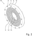
- FIG. 2 It is visible that where the spacer element 50 has been arranged in the middle, in the finished filter element 100, a flow channel 102 is formed, which is open to the edge of the inner receiving bore 101.
- a stack of a total of three filter elements 100 is shown, which are mounted on a support tube 130 indicated only schematically.
- the inner rings 31 of the filter blanks 30 are tight against the outer jacket of the support tube 130.
- the outer rings 32 By the outer rings 32, a seal against the inner shell of the outer ring 14 is effected.
- Adjacent filter elements 100 hold each other by the screw heads and screw shank projections or the nuts at a distance, whereby an outer flow channel 103 is formed between two filter elements 100.
- the flow direction in the production operation runs as indicated by the arrows: from the outer periphery of the filter unit 100 into the outer flow channels 103, from there through the filter blanks 30 to the inner Flow channels 102.
- the latter are, as from the Figures 2 and 4 recognizable, the central receiving bore 101 in the filter elements 100 open.
- the fluid can flow through bores 131 in the tube jacket of the support tube 130 into its interior 130.
- Fig. 4 shows a section of the edge region of a filter element 100 'according to a second embodiment.
- the inner support plate 40 ' here merges seamlessly into a partial outer ring 14', so that a T-shaped cross-section results for this unit in the edge region.
- two identical support plates 40 ' can be used with partial outer ring 14' for both sides.
- a spacer ring 50 ' is clamped therebetween and provides a seal of the inner cavity 102' to the outer periphery. To allow the seal, the spacer ring 50 'has a greater height than the two inwardly facing projections of the part outer rings 14' together.
- an air gap 13 ' remains between the partial outer rings 14'.
- outer support plates 12 ' are in this case formed in their outer edge region as clamping rings 10', that is, they have in this area no openings to the inner cavity out, but only recesses for receiving screws and other fasteners.
- FIG. 5 shows a third embodiment of a filter element 100 ", which is peripherally formed as the previously described second embodiment of a filter element 100", namely with partial outer rings 14 ", which adjoin the outside of the inner support plates 40".
- the support plates 40 '' are concavely curved with respect to the flow direction from the outside in.
- the protruding portions abut each other, but the concave portions are preferably not formed annularly over the entire pitch circle but consist of a plurality of individual bosses. so that radial flow paths from the outer regions of the cavity 102 'to the outlet opening at the inner edge remain open.
- outer support plates 12 "with the integrated clamping rings are flat on the outer surface in this embodiment, being parallel to the contour of the inner support plate, thereby supporting an interposed, also three-dimensionally curved filter element 30" in both flow directions without overstretching.
Landscapes
- Engineering & Computer Science (AREA)
- Mechanical Engineering (AREA)
- Chemical & Material Sciences (AREA)
- Chemical Kinetics & Catalysis (AREA)
- Filtering Of Dispersed Particles In Gases (AREA)
- Filtration Of Liquid (AREA)
- Filtering Materials (AREA)
Description
- Die Erfindung betrifft ein Filterelement für die Filtrierung eines Fluids und eine daraus gebildete Filtereinheit mit den Merkmalen des Oberbegriffs des Anspruchs 1.
- Zur Filtration von hochviskosen Medien wie Kunststoffschmelze werden üblicherweise flächige Siebelemente verwendet. Verunreinigungen in der Kunststoffschmelze wie beispielsweise Aluminiumpartikel oder Papierreste setzen sich an den Filtermedien der Filterelemente ab. Die wirksame Filterfläche ist dabei im Wesentlichen auf den Öffnungsquerschnitt der Siebkavität begrenzt und steht in direktem Zusammenhang mit der Baugröße der Filtriervorrichtung, beispielsweise eines Siebbolzenwechslers.
- Um diesem Nachteil zu begegnen, werden mit Erfolg Filterelemente eingesetzt, wie sie in der
DE 42 12 928 A1 beschrieben sind und die aus Filterscheiben in Form von mehrschichtigen Scheiben bestehen, die mindestens eine Filterschicht und eine Stützschicht aufweisen, die vorzugsweise von einer Deckschicht übergriffen werden. Diese Filterscheiben weisen wiederum eine ringförmige Grundfläche auf, und ihre inneren Randzonen sind jeweils mit den beiden Stirnflächen eines Ringes verbunden. Die äußeren Randzonen der Filterscheiben können dabei über Stirnflächen von Ringen miteinander verbunden sein. Durch die Scheibenform und die Vielzahl der übereinander gestapelten einzelnen Scheibenfilterelemente kann die wirksame Filterfläche bei einer solchen Filtereinheit deutlich vergrößert werden. - Die Filtereinheiten werden insbesondere bei der Filtration von Kunststoffschmelze in eine Siebkavität eines so genannten Siebbolzenwechslers eingesetzt. Dabei wurde jedoch beobachtet, dass sich die einzelnen Filterelemente im anstehenden Fluiddruck wegbiegen können, wodurch es zur Absperrung einzelner Fließwege ebenso kommen kann wie zu Beschädigungen und daraus folgenden Undichtigkeiten des Filterelements.
- Bei zunehmender Verschmutzung ist bei vielen Siebbolzenwechslern vorgesehen, dass der Schmelzestrom auf eine andere Siebkavität mit einem anderen Filterelement umgeleitet wird. Während über letztere der Produktionsstrom aufrecht erhalten wird, kann die verschmutzte Filtereinheit durch einen Rückspülvorgang von den anhaftenden Partikeln befreit werden. Hierzu wird ein Teil der Schmelze in einer zum Normalbetrieb umgekehrtem Fließrichtung durch die Filterelemente der Filtereinheit geleitet, so dass die an den Filtermedien der Filterelemente haftenden Partikel gelöst und weg gespült werden.
- Allerdings ist der bei normalen, flächigen Siebelementen mögliche Rückspülvorgang bei den gattungsgemäßen Filterelementen mit einer Vielzahl von Scheibenfiltern nicht möglich, da das feine metallische Filtergewebe der Filterelemente in der umgekehrten Fließrichtung nicht abgestützt ist und daher bei einer Rückspülung reißen könnte.
- Aufgabe der vorliegenden Erfindung ist es somit, ein Filterelement der eingangs genannten Art so weiter zu entwickeln, dass ein Verbiegen der Filterelemente im Produktionsbetrieb vermieden und somit eine Rückspülung ermöglicht wird.
- Diese Aufgabe wird durch ein Filterelement mit den Merkmalen des Anspruchs 1 gelöst.
- Im Sinne der Erfindung werden unter einem "Ring" nicht nur kreisrunde Formen, sondern auch anders geformte, geschlossene Linien, wie Ellipsen, langlochförmige Konturen oder polygonale Linienzüge verstanden.
- Die inneren Stützplatten stützen die Filtergewebe gegen den im Produktionsbetrieb vorzugsweise von außen einwirkenden Fluiddruck ab. Bei Fließrichtung im Produktionsbetrieb liegen die Filterronden mit einem Teil ihres Außenkantenbereichs gelangt das Fluid bzw. die Kunststoffschmelze von außen auf das Gewebe der Filterronde, und Schmutz wird an der Außenseite zurückgehalten. Der Fluss geht weiter durch die Ausnehmungen der inneren Stützplatten und in den Hohlraum des Filterelements hinein.
- Zusätzlich sind mit Ausnehmungen versehene äußere Stützplatten vorgesehen, so dass die Filterronden sowohl nach innen hin wie auch an den Außenseiten des Filterelements abgedeckt sind bzw. flächig abgestützt werden kann. Damit ist ein Wechsel der Fließrichtung möglich, also auch ein Rückspülbetrieb, bei dem durch Umkehrung der Fließrichtung Anhaftungen von den Filterronden abgespült werden.
- Der Aufbau eines erfindungsgemäßen Filterelements ist sehr robust. Das Filterelement kann sehr einfach zerlegt und gereinigt werden, insbesondere kann es einer thermischen Behandlung unterzogen werden, ohne beschädigt zu werden, um beispielsweise Reste von Kunststoffschmelze auszubrennen.
- Bevorzugt werden die Stützplatten zusätzlich durch wenigstens ein innen liegendes Distanzhalterelement auf Abstand zueinander gehalten, so dass auch bei hohem Druck ein innerer Hohlraum offen gehalten wird, der als Fließkanal dient und der zum Rand der zentralen Bohrung des Filterelements hin offen ist.
- Die Distanzhalterelemente können spinnennetzförmige oder wagenradartige Gebilde, die gesondert einzulegen sind. Sie können aber auch durch vorspringende Absätze am Gehäusering, Spannring oder Außenring gebildet sein.
- Die Distanzhalterelemente können weiterhin durch gewölbte Stützplatten gebildet sein, die sich in Produktionsfließrichtung gesehen konkav oder konvex nach ausdehnen, wobei die Wölbungen so zueinander gewandt sind, dass sie sich partiell berühren, z.B. bei konkaven Formen im Zentrum und bei konvexen Formen im peripheren Randbereich, wodurch die übrigen Flächenbereiche der Stützplatten auf Abstand zueinander gehalten sind.
- Das Filtergewebe kann sich aufgrund seiner Flexibilität gut an die dreidimensionale Form der Stützplatten anpassen, so dass es abgestützt bleibt, auch wenn die Abstützfläche nicht in einer Ebene liegt.
- Auch die äußeren Stützplatten können gewölbt sein, und zwar einmal an der Innenseite, um der Form der inneren Stützplatten zu folgen, damit zu große Dehnungen im dazwischen liegenden Filtergewebes verhindert werden und dieses in beiden Fließrichtungen vollflächig abgestützt bleibt. Zudem kann eine nach außen ragende Wölbung in gleicher Weise einen äußeren Fließkanal abstützen, indem sich die Wölbung wenigstens eines Filterelements an ein benachbartes Filterelement anlegt.
- Die jeweiligen gewölbten inneren und äußeren Oberflächen der inneren und äußeren Stützplatten müssen nicht unbedingt parallel sein, das heißt, die Stützplatte muss nicht unbedingt nach Art eines tiefgezogenen Bleches ausgebildet sein, sondern kann auch einen beidseitig bauchigen Körper bilden.
- Bei den Verbindungselementen handelt es sich vorzugsweise um Schrauben mit Schraubenköpfen und Muttern, so dass mit überall vorhandenen Werkzeugen ein Zerlegen und Zusammensetzen leicht möglich ist.
- Ale einzige Verschleißteile müssen nur die Filterronden ausgetauscht werden, wenn deren metallisches, gegebenenfalls mehrlagiges Filtergewebe zu stark beschädigt ist.
- Die äußeren Stützplatten können jeweils in den Spannring integriert sein. Sie können aber auch als separate Platten unter den Spannring gelegt werden.
- Vorzugsweise sind die Stützplatten als Lochplatten ausgebildet, die einfach zu fertigen sind und durch ihre Gitterstruktur eine kleinflächige Abstützung von Filtergewebe ermöglichen.
- Vorzugsweise besitzen die Filterronden einen Innenring und einen Außenring, welche vorzugsweise aus einem Nicht-Eisen-Metall, insbesondere aus Kupfer, bestehen. Damit wird eine metallische Dichtung geschaffen, einmal am Innenumfang als Abdichtung zu einem innen liegenden Stützrohr, auf dem die Filterelemente gestapelt sind, und einmal am Außenumfang als Abdichtung gegenüber dem Außenring.
- Möglich ist aber auch, die ringscheibenförmigen Filterronden mit Übermaß am Innen- und/oder Außenrand gegenüber den angrenzenden Bauteilen zu fertigen und diese dann entsprechend auf die angrenzenden Bauteile anzupressen.
- Der Außenring kann einteilig mit dem Spannring oder der inneren Stützplatte ausgebildet sein.
- Eine bevorzugte Ausführungsform der Erfindung sieht vor, gleichartige innere Stützplatten zu verwenden, die am Außenumfang jeweils mittig auf einem Teil-Außenring münden. Es ergibt sich dann ein T-förmiger Querschnitt am Rand jeder inneren Stützplatte. Es können zur Bildung eines Filterelements je zwei Stück von insgesamt drei gleichartigen Teilen verwendet werden, nämlich zwei gleiche innere Stützplatten mit Teil-Außenring, zwei gleiche Filterronden und zwei gleiche äußere Stützplatten, die zugleich randseitig den Spannring integrieren. Damit ist eine kostengünstige Herstellung und Lagerhaltung ebenso möglich wie eine einfache Handhabung.
- Eine aus mehreren erfindungsgemäßen Filterelementen gebildete Filtereinheit gemäß Anspruch 12 ist einfach aufzubauen und zu Reinigungszwecken ebenso leicht zu demontieren, da die erfindungsgemäßen Filterelemente durch ihr massives äußeres Gehäuse, bestehend aus Außenring, Stützplatten und Spannringen unempfindlich gegenüber Stößen und Schlägen sind.
- Dadurch, dass die Verbindungselemente an den Stirnseiten des fertigen Filterelements überstehen, können die Überstände gleichzeitig als Abstandshalter dienen, wodurch Fließkanäle zwischen benachbarten Filterelementen ausgebildet werden. Aufeinander gestapelte Filterelemente stützen sich somit gegeneinander ab, und können vom Fluiddruck nicht weggebogen werden.
- Eine bevorzugte Ausführungsform sieht ein zusätzliches Grobfilterelement vor, das die Filterelemente umschließt und das sich zwischen einem Boden der Filtereinheit oder dem Boden einer Siebkavität, in welche die Filtereinheit eingesetzt ist, und deren Kopfplatte erstreckt.
- An dem Grobfilterelement werden beispielsweise Partikel wie Aluminium- oder Papierreste zurückgehalten, die gerade beim Kunststoffrecycling anfallen und die teilweise so groß sind, dass sie durch eine Rückspülung aus dem Fließkanal zwischen den Filterelementen nicht mehr oder nur schwer entfernbar wären. Damit wird eine Kaskadenfiltration erreicht, bei der grobe Partikel gar nicht mehr in das Innere der eigentlichen Filtereinheit gelangen. Deren Aufgabe ist somit auf die Abscheidung feiner Artikel oder Agglomerate beschränkt, was zu einer deutlich erhöhten Standzeit führt.
- Die Erfindung wird nachfolgend mit Bezug auf die Zeichnung näher erläutert. Die Figuren zeigen im Einzelnen:
- Fig. 1
- ein Filterelement gemäß einer ersten Ausführungsform in Explosionsdarstellung;
- Fig. 2
- ein montiertes Filterelement gemäß der ersten Ausführungsform in perspektivischer Darstellung;
- Fig. 3
- mehrere auf einem Stützrohr gestapelte Filterelemente im Schnitt und
- Fig. 4
- einen randseitigen Ausschnitt einer Schnittansicht einer zweiten Ausführungsform eines Filterelements; und
- Fig. 4
- einen randseitigen Ausschnitt einer Schnittansicht einer dritten Ausführungsform eines Filterelements.
-
Figur 1 zeigt ein Filterelement 100 mit seinen Bestandteilen in lagerichtiger Anordnung vor der Montage. - Wesentliche Bestandteile sind in der Montagereihenfolge von links nach rechts:
- Ein Spannring 10 mit Durchgangsbohrungen 11 zur Aufnahme von Schrauben, mit einem integrierten zylindrischen Außenring 14 und mit einer integrierten Stützplatte 12.
- Eine erste ringscheibenförmige Filterronde 30, welche an ihrem Innenrand mit einem Innenring 31 und an ihrem Außenrand mit einem Außenring 32 eingefasst ist, welche Ringe 31, 32 aus einem Kupferprofil bestehen.
- Eine als Lochscheibe ausgebildete, innen liegende, erste Stützplatte 40.
- Ein Distanzhalterelement 50, welches die erste innere Stützplatte 40 in einem Abstand zu einer zweiten inneren Stützplatte 40 hält.
- Eine zweite Filterronde 30.
- Ein Spannring 20 mit Durchgangsbohrungen zur Aufnahme von Schrauben 21. Der Spannring 20 besitzt bei dieser Ausführungsform, wie der Spannring 10 auch, eine integrierte zentrale Stützplatte 22.
-
Figur 2 zeigt das fertig montierte Filterelement 100. Sichtbar ist darin, dass dort, wo das Distanzhalterelement 50 in der Mitte angeordnet worden ist, beim fertigen Filterelement 100 ein Fließkanal 102 ausgebildet ist, der zum Rand der inneren Aufnahmebohrung 101 hin offen liegt. - In
Fig. 3 ist ein Stapel von insgesamt drei Filterelementen 100 gezeigt, die auf ein nur schematisch angedeutetes Stützrohr 130 aufgezogen sind. Dabei liegen die Innenringe 31 der Filterronden 30 dicht am Außenmantel des Stützrohrs 130 an. Durch die Außenringe 32 wird eine Abdichtung gegenüber dem Innenmantel des Außenrings 14 bewirkt. Benachbarte Filterelemente 100 halten sich durch die Schraubenköpfe und Schraubenschaftüberstände bzw. die Muttern gegenseitig auf Abstand, wodurch sich zwischen zwei Filterelementen 100 ein äußerer Fließkanal 103 ausbildet. - Die Fließrichtung im Produktionsbetrieb verläuft wie durch die Pfeile angedeutet: vom Außenumfang der Filtereinheit 100 in die äußeren Fließkanäle 103 hinein, von dort durch die Filterronden 30 hindurch bis in die inneren Fließkanäle 102. Letztere sind, wie aus den
Figuren 2 und4 erkennbar, zur zentralen Aufnahmebohrung 101 in den Filterelementen 100 hin offen. Dadurch kann das Fluid durch Bohrungen 131 im Rohrmantel des Stützrohrs 130 in dessen Innenraum 130 abfließen. -
Fig. 4 zeigt einen Ausschnitt aus dem Randbereich eines Filterelements 100' gemäß einer zweiten Ausführungsform. Die innere Stützplatte 40' geht hier jeweils nahtlos in einen Teil-Außenring 14' über, so dass sich für diese Einheit im Randbereich ein T-förmiger Querschnitt ergibt. Durch die vorzugsweise spiegelsymmetrische Ausbildung können zwei identische Stützplatten 40' mit Teil-Außenring 14' für beide Seiten verwendet werden. Ein Distanzring 50' wird dazwischen eingeklemmt und sorgt für eine Abdichtung des inneren Hohlraums 102' zum Außenumfang hin. Um die Abdichtung zu ermöglichen, hat der Distanzring 50' eine größere Höhe als die beiden nach innen weisenden Überstände der Teil-Außenringe 14' zusammen. Somit verbleibt zwischen den Teil-Außenringen 14' ein Luftspalt 13'. Möglicht wird dadurch, mit einer Verschraubung, die hier nur angedeutet ist, zwei identische Einheiten aus äußeren Stützplatten 12', Filterelementen 30' und inneren Stützplatten 40' unter Einschluss des Distanzrings 50' gegeneinander zu verspannen, so dass sich insgesamt ein Filterelement 100' ergibt, das eine nach außen abgedichtete Einheit ist. Die äußeren Stützplatten 12' sind hierbei in ihrem äußeren Randbereich als Spannringe 10' ausgebildet, das heißt, sie besitzen in diesem Bereich keine Durchbrechungen zum inneren Hohlraum hin, sondern nur Ausnehmungen zur Aufnahme von Schrauben und andere Verbindungselementen. -
Figur 5 zeigt eine dritte Ausführungsform eines Filterelements 100", die randseitig so ausgebildet ist wie die zuvor beschrieben zweite Ausführungsform eines Filterelements 100", nämlich mit Teil-Außenringen 14", die sich außen an die inneren Stützplatten 40" anschließen. Bei dem Ausführungsbeispiel sind die Stützplatten 40" jedoch - in Bezug auf die Fließrichtung von außen nach innen - konkav gewölbt. Die vorstehenden Bereiche stoßen aneinander, jedoch sind die konkaven Bereiche vorzugsweise nicht ringförmig über den gesamten Teilkreis ausgebildet, sondern bestehen aus mehrerer einzelnen Buckel, so dass auch radiale Fließwege von den äußeren Bereichen des Hohlraums 102' zur Austrittsöffnung am Innenrand offen bleiben. - Die äußeren Stützplatten 12" mit den integrierten Spannringen sind bei diesem Ausführungsbeispiel an der Außenoberfläche eben, wobei sie innen parallel zur Kontur der inneren Stützplatte sind. Dadurch wird ein dazwischen eingelegtes, ebenfalls dreidimensional gewölbtes Filterelement 30" in beiden Fließrichtungen abgestützt ohne zu überstrecken.
Claims (14)
- Filterelement (100; 100'; 100") für die Filtrierung eines Fluids, das wenigstens folgende, in dieser Reihenfolge entlang einer Mittelachse angeordnete Einzelteile umfasst:- einen an einer Stirnseite des Filterelements (100;100') angeordneten ersten Spannring (10; 10') ;- eine erste Filterronde (30; 30'; 30"),- eine erste mit Ausnehmungen versehene innere Stützplatte (40; 40'; 40") zur Abstützung der ersten Filterronde (30; 30'; 30");- eine zweite mit Ausnehmungen versehene, innere Stützplatte (40; 40'; 40");- eine zweite, an der zweiten inneren Stützplatte (40; 40'; 40") angeordnete Filterronde (30; 30'; 30"), und- einen an der anderen Stirnseite angeordneten zweiten Spannring (20; 10'), der über Verbindungselemente (21) mit dem ersten Spannring (10) verbunden ist,- wobei zwischen der ersten und zweiten inneren Stützplatte (40; 40'; 40") ein innerer Fließkanal (102; 102') gebildet ist,dadurch gekennzeichnet, dass die Filterronden (30; 30'; 30") und die inneren Stützplatten (40; 40'; 40") innerhalb eines Gehäuses angeordnet sind, das durch die Spannringe (10, 20; 10'), wenigstens einen Außenring (14; 14'; 14"), und durch mit Ausnehmungen versehene äußere Stützplatten (12, 22; 12', 12") gebildet ist, welche die Filterronden (30; 30'; 30") jeweils außen abdecken.
- Filterelement (100; 100') nach Anspruch 1, dadurch gekennzeichnet, dass zwischen den inneren Stützplatten (40, 40') wenigstens ein Distanzhalterelement (50, 50') zur Ausbildung des inneren Fließkanals (102; 102') angeordnet ist.
- Filterelement (100") nach Anspruch 1, dadurch gekennzeichnet, dass wenigstens eine innere Stützplatte (40") durch an zur Abstützung des inneren Fließkanals (102') zumindest an ihrer Innenseite gewölbt ausgebildet ist.
- Filterelement (100") nach wenigstens einem der Ansprüche 1 bis 3, dadurch gekennzeichnet, dass wenigstens eine äußeren Stützplatte (12") an ihrer inneren Oberfläche gewölbt sind.
- Filterelement nach wenigstens einem der Ansprüche 1 bis 4, dadurch gekennzeichnet, dass wenigstens eine äußere Stützplatte an ihrer äußeren Oberfläche gewölbt ist.
- Filterelement (100; 100'; 100") nach wenigstens einem der Ansprüche 1 bis 5, dadurch gekennzeichnet, dass wenigstens eine äußere Stützplatte (12, 22; 12'; 12") in den Spannring (10, 20; 10') integriert ist.
- Filterelement (100) nach wenigstens einem der Ansprüche 1 bis 6, dadurch gekennzeichnet, dass die Filterronde (30) einen Innenring (31) und einen Außenring (32) umfasst, zwischen denen wenigstens ein ringförmiges Filtermedium (33) gehalten ist.
- Filterelement (100) nach Anspruch 7, dadurch gekennzeichnet, dass der Innenring (31) und/oder der Außenring (32) der Filterronden (30) aus einem Nicht-Eisen-Metall besteht/bestehen.
- Filterelement nach wenigstens einem der Ansprüche 1 bis 8, dadurch gekennzeichnet, dass dem Filterelement (100) ein Stützrohr zugeordnet und die Filterronde ringscheibenförmig ist und an ihrem Innenrand ein Untermaß gegenüber dem Außendurchmesser eines innen anzuordnenden Stützrohrs und/oder an ihrem Außenrand ein Übermaß gegenüber dem Innendurchmesser des Außenrings aufweist.
- Filterelement (100) nach wenigstens einem der Ansprüche 1 bis 9, dadurch gekennzeichnet, dass der Außenring (14) einteilig mit einem Spannring (10) ausgebildet ist.
- Filterelement (100'; 100") nach wenigstens einem der Ansprüche 1 bis 10, dadurch gekennzeichnet, dass das Filterelement zwei gleichartige innere Stützplatten(40'; 40") umfasst, die am Außenumfang jeweils mittig auf einem Teil-Außenring (14'; 14") münden, wobei sich ein T-förmiger Querschnitt im jeweiligen Randbereich der inneren Stützplatte (40'; 14") ergibt.
- Filterelement (100'; 100") nach einem der vorstehenden Ansprüche,
dadurch gekennzeichnet, dass die Verbindungselemente (21) als Schrauben mit Schraubenköpfen und Muttern ausgebildet sind. - Filtereinheit für eine Filtriereinrichtung, wenigstens umfassend:- ein Stützrohr (130) mit einem Rohrmantel, das mehrere Ausnehmungen (131) im Rohrmantel aufweist,- mehrere gestapelte Filterelemente (100; 100') nach wenigstens einem der vorhergehenden Ansprüche, die auf dem Stützrohr (130) zentriert sind,
wobei die Verbindungselemente (21) über den Spannring (20) nach außen vorstehen und wobei durch deren Überstand zwischen benachbarten Filterelementen (100; 100') ein Eintrittsfließkanal (103) ausgebildet ist, welcher sich in einem Fließkanal fortsetzt, welcher durch die Filterronden (30) hindurch in den inneren Fließkanal (102) der Filterelemente (100, 100') bis zu jeweils wenigstens einer Ausnehmung (131) im Stützrohr (130) führt;- und eine am Stützrohr (30) angebrachte und den Stapel von Filterelementen (100; 100') überdeckende Kopfplatte. - Filtereinheit nach Anspruch 13, gekennzeichnet durch ein zusätzliches Grobfilterelement, das die Filterelemente (100) umschließt und das sich zwischen einem Boden der Filtereinheit oder dem Boden einer Siebkavität, in welche die Filtereinheit eingesetzt ist, und der Kopfplatte der Filtereinheit erstreckt.
Applications Claiming Priority (2)
| Application Number | Priority Date | Filing Date | Title |
|---|---|---|---|
| DE102011001015.7A DE102011001015B4 (de) | 2011-03-02 | 2011-03-02 | Filterelement für die Filtrierung eines Fluids und daraus gebildete Filtereinheit |
| PCT/EP2012/053690 WO2012117114A1 (de) | 2011-03-02 | 2012-03-02 | Filterelement für die filtrierung eines fluids und daraus gebildete filtereinheit |
Publications (2)
| Publication Number | Publication Date |
|---|---|
| EP2680936A1 EP2680936A1 (de) | 2014-01-08 |
| EP2680936B1 true EP2680936B1 (de) | 2017-02-01 |
Family
ID=45841455
Family Applications (1)
| Application Number | Title | Priority Date | Filing Date |
|---|---|---|---|
| EP12709037.1A Active EP2680936B1 (de) | 2011-03-02 | 2012-03-02 | Filterelement für die filtrierung eines fluids und daraus gebildete filtereinheit |
Country Status (6)
| Country | Link |
|---|---|
| US (1) | US11491424B2 (de) |
| EP (1) | EP2680936B1 (de) |
| JP (1) | JP6101639B2 (de) |
| CN (1) | CN103582516B (de) |
| DE (1) | DE102011001015B4 (de) |
| WO (1) | WO2012117114A1 (de) |
Families Citing this family (11)
| Publication number | Priority date | Publication date | Assignee | Title |
|---|---|---|---|---|
| JP6243747B2 (ja) * | 2014-02-04 | 2017-12-06 | Nok株式会社 | 押出機用ストレーナ |
| CN104289023B (zh) * | 2014-10-31 | 2016-01-13 | 茆正伟 | 一种污泥滤压脱水机 |
| CN106541556A (zh) * | 2016-12-14 | 2017-03-29 | 泗县鸿盛塑业有限公司 | 挤塑机过滤装置 |
| DE102017100032B3 (de) * | 2017-01-02 | 2018-05-24 | Gneuss Gmbh | Siebrad-Filtriervorrichtung für mittel- bis hochviskose Fluide und Abdicht- und Montageverfahren dafür |
| CN109126253B (zh) * | 2018-09-01 | 2020-11-06 | 华迪钢业集团有限公司 | 单面中空不锈钢过滤板 |
| AT521976B1 (de) * | 2019-05-21 | 2020-07-15 | Mag Katharina Schulz | Schmelzefilter |
| EP4211222A4 (de) | 2020-09-08 | 2024-10-16 | Sunflower Therapeutics, PBC | Zellrückhaltevorrichtung |
| CN112807772A (zh) * | 2021-03-03 | 2021-05-18 | 联合滤洁过滤技术(武汉)有限公司 | 一种蝶式水过滤反洗滤芯 |
| US12220657B2 (en) * | 2021-04-30 | 2025-02-11 | Pall Corporation | Filter disk segments |
| CN113698021B (zh) * | 2021-09-13 | 2026-01-13 | 上海知楚实业有限公司 | 一种生物仪器冷凝水循环利用装置 |
| CN119303374B (zh) * | 2024-12-16 | 2025-05-23 | 洛阳德锐环保科技有限公司 | 一种熔体过滤器 |
Family Cites Families (26)
| Publication number | Priority date | Publication date | Assignee | Title |
|---|---|---|---|---|
| FR780398A (fr) * | 1934-10-27 | 1935-04-25 | Algerienne Des App Gasquet Soc | Filtre |
| US3019905A (en) * | 1959-12-15 | 1962-02-06 | Swimquip Inc | Filter element and assembly |
| JPS5220705B2 (de) | 1974-10-29 | 1977-06-06 | ||
| US3919533A (en) | 1974-11-08 | 1975-11-11 | Westinghouse Electric Corp | Electrical fault indicator |
| JPS5343824Y2 (de) * | 1974-11-29 | 1978-10-20 | ||
| US3905787A (en) * | 1974-12-23 | 1975-09-16 | Monsanto Co | Filter |
| EP0163742A4 (de) * | 1983-12-05 | 1988-01-21 | Keiichi Murakami | Filteranordnung für polymere. |
| JPS6198517A (ja) | 1984-10-22 | 1986-05-16 | Toray Ind Inc | 溶融ポリマ用濾材 |
| JPS6275813A (ja) | 1985-09-30 | 1987-04-07 | Mitsubishi Electric Corp | 速度制御装置 |
| JPS6275813U (de) * | 1985-10-31 | 1987-05-15 | ||
| EP0267108A1 (de) | 1986-10-31 | 1988-05-11 | Digital Equipment Corporation | Miniaturisierter Transformator |
| DE3644489C1 (de) * | 1986-12-24 | 1988-08-18 | Filtan Gmbh | Vorrichtung zur Abscheidung von Verunreinigungen |
| EP0284404B1 (de) | 1987-03-27 | 1994-05-18 | Pall Corporation | Filterscheibe |
| JPH064893Y2 (ja) * | 1987-04-30 | 1994-02-09 | 株式会社土屋製作所 | 精密フィルタユニット |
| US4881313A (en) | 1988-02-03 | 1989-11-21 | Cuno, Incorporated | Method of forming a cell filter with an exposed surface |
| JPH0354719A (ja) | 1989-07-24 | 1991-03-08 | Matsushita Electric Ind Co Ltd | 磁気記録媒体 |
| JPH0354719U (de) * | 1989-09-25 | 1991-05-27 | ||
| US5637213A (en) * | 1990-08-30 | 1997-06-10 | Henry Filters, Inc. | Immersible filter drum unit and method for assembling thereof |
| DE4212928A1 (de) | 1992-04-21 | 1993-10-28 | Gneuss Kunststofftechnik Gmbh | Filter für Kunststoffschmelzen |
| FI92289C (fi) * | 1993-05-06 | 1994-10-25 | Ahlstroem Oy | Kiekkosuodattimen sektori |
| JPH0810522A (ja) * | 1994-06-30 | 1996-01-16 | Fuji Filter Kogyo Kk | 高粘度流体用フィルター |
| US20030213742A1 (en) * | 2001-04-27 | 2003-11-20 | Decoste David | Filter cartrdiges and methods of manufacturing same |
| US6866777B2 (en) * | 2001-10-19 | 2005-03-15 | Joseph Kuo | Laminated modular water filter |
| JP2003290610A (ja) | 2002-04-02 | 2003-10-14 | Kyuno Kk | 積層型フィルタモジュール |
| JP2007537444A (ja) | 2004-05-14 | 2007-12-20 | コンティニューム ダイナミクス,インコーポレイテッド | 輪郭付け構造の面を有する低水頭損失のモジュール式吸込ストレーナ |
| MX2011002835A (es) * | 2008-09-18 | 2011-08-17 | Norbert Assion | Montaje de filtro. |
-
2011
- 2011-03-02 DE DE102011001015.7A patent/DE102011001015B4/de not_active Expired - Fee Related
-
2012
- 2012-03-02 EP EP12709037.1A patent/EP2680936B1/de active Active
- 2012-03-02 CN CN201280011206.3A patent/CN103582516B/zh active Active
- 2012-03-02 WO PCT/EP2012/053690 patent/WO2012117114A1/de not_active Ceased
- 2012-03-02 US US14/002,384 patent/US11491424B2/en active Active
- 2012-03-02 JP JP2013555896A patent/JP6101639B2/ja active Active
Also Published As
| Publication number | Publication date |
|---|---|
| WO2012117114A1 (de) | 2012-09-07 |
| EP2680936A1 (de) | 2014-01-08 |
| US11491424B2 (en) | 2022-11-08 |
| CN103582516B (zh) | 2016-10-12 |
| JP2014506833A (ja) | 2014-03-20 |
| DE102011001015A1 (de) | 2012-12-27 |
| DE102011001015B4 (de) | 2016-03-03 |
| CN103582516A (zh) | 2014-02-12 |
| JP6101639B2 (ja) | 2017-03-22 |
| US20140291231A1 (en) | 2014-10-02 |
Similar Documents
| Publication | Publication Date | Title |
|---|---|---|
| EP2680936B1 (de) | Filterelement für die filtrierung eines fluids und daraus gebildete filtereinheit | |
| EP2754476B1 (de) | Kreissegment zur Aufnahme eines Filtersegments | |
| EP1506048B1 (de) | Filtervorrichtung in segmentbauweise | |
| DE68908179T2 (de) | Wellensiebplatte und verfahren zu deren herstellung. | |
| DE102018105586A1 (de) | Rotor eines Zentrifugalabscheiders und Zentrifugalabscheider | |
| DE3333589A1 (de) | Filterkassette | |
| EP0885044B1 (de) | Konischer fluidfilter | |
| DE69905251T2 (de) | Filterelement zur verwendung in einer filtervorrichtung | |
| DE102011001021B4 (de) | Filtereinheit für ein Siebträgerelement für eine Filtriereinrichtung | |
| DE102014108935B4 (de) | Abdeckung für eine Bremse oder einen Bereich einer Bremse oder ein Rad eines Fahrzeuges, insbesondere Bremsabdeckblech | |
| EP1231996B1 (de) | Pressmembran aus einem gummielastischen material | |
| WO2011138271A1 (de) | Filterplatte für eine filterpresse und filterpaket | |
| AT363407B (de) | Trennvorrichtung | |
| EP0872280B1 (de) | Verschleissfeste Oberflächenpanzerung für die Walzen von Walzenmühlen zur Druckzerkleinerung körnigen Gutes | |
| DE102011001017B4 (de) | Rückspülbare Filtereinheit für ein Siebträgerelement für eine Filtriereinrichtung | |
| EP1159997B1 (de) | Membranfilterplatte für eine Filterpresse sowie Trägerplatte und Membran für eine solche Membranfilterplatte | |
| DE2705560C3 (de) | Filter für Polymerschmelzen und Polymerlösungen | |
| EP3342471B1 (de) | Filter mit verstärkter deckelbefestigung | |
| DE3409036A1 (de) | Rueckspuelfilter, insbesondere brauchwasserfilter mit wenigstens einer filterkerze aus uebereinander angeordneten ringscheiben | |
| EP0754891A1 (de) | Dichtungsring | |
| WO2024251487A1 (de) | Filtersystem mit wenigstens zwei filterelementen | |
| DE3007883A1 (de) | Trennvorrichtung | |
| DE1461474A1 (de) | Filter | |
| DE4408388A1 (de) | Membranfilterpresse und Verfahren zur Herstellung ihrer Membranträgerplatten | |
| DE1761325B2 (de) | Filtereinsatz für Flüssigkeitsfilter |
Legal Events
| Date | Code | Title | Description |
|---|---|---|---|
| PUAI | Public reference made under article 153(3) epc to a published international application that has entered the european phase |
Free format text: ORIGINAL CODE: 0009012 |
|
| 17P | Request for examination filed |
Effective date: 20131001 |
|
| AK | Designated contracting states |
Kind code of ref document: A1 Designated state(s): AL AT BE BG CH CY CZ DE DK EE ES FI FR GB GR HR HU IE IS IT LI LT LU LV MC MK MT NL NO PL PT RO RS SE SI SK SM TR |
|
| DAX | Request for extension of the european patent (deleted) | ||
| RAP1 | Party data changed (applicant data changed or rights of an application transferred) |
Owner name: NORDSON HOLDINGS S.A R.L. & CO. KG |
|
| GRAP | Despatch of communication of intention to grant a patent |
Free format text: ORIGINAL CODE: EPIDOSNIGR1 |
|
| INTG | Intention to grant announced |
Effective date: 20160310 |
|
| GRAS | Grant fee paid |
Free format text: ORIGINAL CODE: EPIDOSNIGR3 |
|
| GRAJ | Information related to disapproval of communication of intention to grant by the applicant or resumption of examination proceedings by the epo deleted |
Free format text: ORIGINAL CODE: EPIDOSDIGR1 |
|
| GRAL | Information related to payment of fee for publishing/printing deleted |
Free format text: ORIGINAL CODE: EPIDOSDIGR3 |
|
| INTC | Intention to grant announced (deleted) | ||
| GRAR | Information related to intention to grant a patent recorded |
Free format text: ORIGINAL CODE: EPIDOSNIGR71 |
|
| STAA | Information on the status of an ep patent application or granted ep patent |
Free format text: STATUS: GRANT OF PATENT IS INTENDED |
|
| INTG | Intention to grant announced |
Effective date: 20161115 |
|
| GRAA | (expected) grant |
Free format text: ORIGINAL CODE: 0009210 |
|
| STAA | Information on the status of an ep patent application or granted ep patent |
Free format text: STATUS: THE PATENT HAS BEEN GRANTED |
|
| AK | Designated contracting states |
Kind code of ref document: B1 Designated state(s): AL AT BE BG CH CY CZ DE DK EE ES FI FR GB GR HR HU IE IS IT LI LT LU LV MC MK MT NL NO PL PT RO RS SE SI SK SM TR |
|
| REG | Reference to a national code |
Ref country code: GB Ref legal event code: FG4D Free format text: NOT ENGLISH |
|
| REG | Reference to a national code |
Ref country code: CH Ref legal event code: EP Ref country code: AT Ref legal event code: REF Ref document number: 865059 Country of ref document: AT Kind code of ref document: T Effective date: 20170215 |
|
| REG | Reference to a national code |
Ref country code: IE Ref legal event code: FG4D Free format text: LANGUAGE OF EP DOCUMENT: GERMAN |
|
| REG | Reference to a national code |
Ref country code: DE Ref legal event code: R096 Ref document number: 502012009435 Country of ref document: DE |
|
| REG | Reference to a national code |
Ref country code: CH Ref legal event code: NV Representative=s name: WEINMANN ZIMMERLI AG, CH |
|
| REG | Reference to a national code |
Ref country code: NL Ref legal event code: MP Effective date: 20170201 |
|
| REG | Reference to a national code |
Ref country code: LT Ref legal event code: MG4D |
|
| PG25 | Lapsed in a contracting state [announced via postgrant information from national office to epo] |
Ref country code: HR Free format text: LAPSE BECAUSE OF FAILURE TO SUBMIT A TRANSLATION OF THE DESCRIPTION OR TO PAY THE FEE WITHIN THE PRESCRIBED TIME-LIMIT Effective date: 20170201 Ref country code: GR Free format text: LAPSE BECAUSE OF FAILURE TO SUBMIT A TRANSLATION OF THE DESCRIPTION OR TO PAY THE FEE WITHIN THE PRESCRIBED TIME-LIMIT Effective date: 20170502 Ref country code: IS Free format text: LAPSE BECAUSE OF FAILURE TO SUBMIT A TRANSLATION OF THE DESCRIPTION OR TO PAY THE FEE WITHIN THE PRESCRIBED TIME-LIMIT Effective date: 20170601 Ref country code: LT Free format text: LAPSE BECAUSE OF FAILURE TO SUBMIT A TRANSLATION OF THE DESCRIPTION OR TO PAY THE FEE WITHIN THE PRESCRIBED TIME-LIMIT Effective date: 20170201 Ref country code: FI Free format text: LAPSE BECAUSE OF FAILURE TO SUBMIT A TRANSLATION OF THE DESCRIPTION OR TO PAY THE FEE WITHIN THE PRESCRIBED TIME-LIMIT Effective date: 20170201 Ref country code: NO Free format text: LAPSE BECAUSE OF FAILURE TO SUBMIT A TRANSLATION OF THE DESCRIPTION OR TO PAY THE FEE WITHIN THE PRESCRIBED TIME-LIMIT Effective date: 20170501 |
|
| PG25 | Lapsed in a contracting state [announced via postgrant information from national office to epo] |
Ref country code: NL Free format text: LAPSE BECAUSE OF FAILURE TO SUBMIT A TRANSLATION OF THE DESCRIPTION OR TO PAY THE FEE WITHIN THE PRESCRIBED TIME-LIMIT Effective date: 20170201 Ref country code: RS Free format text: LAPSE BECAUSE OF FAILURE TO SUBMIT A TRANSLATION OF THE DESCRIPTION OR TO PAY THE FEE WITHIN THE PRESCRIBED TIME-LIMIT Effective date: 20170201 Ref country code: SE Free format text: LAPSE BECAUSE OF FAILURE TO SUBMIT A TRANSLATION OF THE DESCRIPTION OR TO PAY THE FEE WITHIN THE PRESCRIBED TIME-LIMIT Effective date: 20170201 Ref country code: PL Free format text: LAPSE BECAUSE OF FAILURE TO SUBMIT A TRANSLATION OF THE DESCRIPTION OR TO PAY THE FEE WITHIN THE PRESCRIBED TIME-LIMIT Effective date: 20170201 Ref country code: ES Free format text: LAPSE BECAUSE OF FAILURE TO SUBMIT A TRANSLATION OF THE DESCRIPTION OR TO PAY THE FEE WITHIN THE PRESCRIBED TIME-LIMIT Effective date: 20170201 Ref country code: BG Free format text: LAPSE BECAUSE OF FAILURE TO SUBMIT A TRANSLATION OF THE DESCRIPTION OR TO PAY THE FEE WITHIN THE PRESCRIBED TIME-LIMIT Effective date: 20170501 Ref country code: LV Free format text: LAPSE BECAUSE OF FAILURE TO SUBMIT A TRANSLATION OF THE DESCRIPTION OR TO PAY THE FEE WITHIN THE PRESCRIBED TIME-LIMIT Effective date: 20170201 Ref country code: PT Free format text: LAPSE BECAUSE OF FAILURE TO SUBMIT A TRANSLATION OF THE DESCRIPTION OR TO PAY THE FEE WITHIN THE PRESCRIBED TIME-LIMIT Effective date: 20170601 |
|
| PG25 | Lapsed in a contracting state [announced via postgrant information from national office to epo] |
Ref country code: SK Free format text: LAPSE BECAUSE OF FAILURE TO SUBMIT A TRANSLATION OF THE DESCRIPTION OR TO PAY THE FEE WITHIN THE PRESCRIBED TIME-LIMIT Effective date: 20170201 Ref country code: RO Free format text: LAPSE BECAUSE OF FAILURE TO SUBMIT A TRANSLATION OF THE DESCRIPTION OR TO PAY THE FEE WITHIN THE PRESCRIBED TIME-LIMIT Effective date: 20170201 Ref country code: CZ Free format text: LAPSE BECAUSE OF FAILURE TO SUBMIT A TRANSLATION OF THE DESCRIPTION OR TO PAY THE FEE WITHIN THE PRESCRIBED TIME-LIMIT Effective date: 20170201 Ref country code: EE Free format text: LAPSE BECAUSE OF FAILURE TO SUBMIT A TRANSLATION OF THE DESCRIPTION OR TO PAY THE FEE WITHIN THE PRESCRIBED TIME-LIMIT Effective date: 20170201 |
|
| REG | Reference to a national code |
Ref country code: DE Ref legal event code: R097 Ref document number: 502012009435 Country of ref document: DE |
|
| PG25 | Lapsed in a contracting state [announced via postgrant information from national office to epo] |
Ref country code: DK Free format text: LAPSE BECAUSE OF FAILURE TO SUBMIT A TRANSLATION OF THE DESCRIPTION OR TO PAY THE FEE WITHIN THE PRESCRIBED TIME-LIMIT Effective date: 20170201 Ref country code: SM Free format text: LAPSE BECAUSE OF FAILURE TO SUBMIT A TRANSLATION OF THE DESCRIPTION OR TO PAY THE FEE WITHIN THE PRESCRIBED TIME-LIMIT Effective date: 20170201 Ref country code: MC Free format text: LAPSE BECAUSE OF FAILURE TO SUBMIT A TRANSLATION OF THE DESCRIPTION OR TO PAY THE FEE WITHIN THE PRESCRIBED TIME-LIMIT Effective date: 20170201 |
|
| PLBE | No opposition filed within time limit |
Free format text: ORIGINAL CODE: 0009261 |
|
| STAA | Information on the status of an ep patent application or granted ep patent |
Free format text: STATUS: NO OPPOSITION FILED WITHIN TIME LIMIT |
|
| REG | Reference to a national code |
Ref country code: IE Ref legal event code: MM4A |
|
| REG | Reference to a national code |
Ref country code: FR Ref legal event code: ST Effective date: 20171130 |
|
| 26N | No opposition filed |
Effective date: 20171103 |
|
| GBPC | Gb: european patent ceased through non-payment of renewal fee |
Effective date: 20170501 |
|
| PG25 | Lapsed in a contracting state [announced via postgrant information from national office to epo] |
Ref country code: LU Free format text: LAPSE BECAUSE OF NON-PAYMENT OF DUE FEES Effective date: 20170302 Ref country code: FR Free format text: LAPSE BECAUSE OF NON-PAYMENT OF DUE FEES Effective date: 20170403 |
|
| PG25 | Lapsed in a contracting state [announced via postgrant information from national office to epo] |
Ref country code: SI Free format text: LAPSE BECAUSE OF FAILURE TO SUBMIT A TRANSLATION OF THE DESCRIPTION OR TO PAY THE FEE WITHIN THE PRESCRIBED TIME-LIMIT Effective date: 20170201 Ref country code: IE Free format text: LAPSE BECAUSE OF NON-PAYMENT OF DUE FEES Effective date: 20170302 |
|
| REG | Reference to a national code |
Ref country code: BE Ref legal event code: MM Effective date: 20170331 |
|
| PG25 | Lapsed in a contracting state [announced via postgrant information from national office to epo] |
Ref country code: GB Free format text: LAPSE BECAUSE OF NON-PAYMENT OF DUE FEES Effective date: 20170501 |
|
| PG25 | Lapsed in a contracting state [announced via postgrant information from national office to epo] |
Ref country code: BE Free format text: LAPSE BECAUSE OF NON-PAYMENT OF DUE FEES Effective date: 20170331 |
|
| PG25 | Lapsed in a contracting state [announced via postgrant information from national office to epo] |
Ref country code: MT Free format text: LAPSE BECAUSE OF FAILURE TO SUBMIT A TRANSLATION OF THE DESCRIPTION OR TO PAY THE FEE WITHIN THE PRESCRIBED TIME-LIMIT Effective date: 20170201 |
|
| PG25 | Lapsed in a contracting state [announced via postgrant information from national office to epo] |
Ref country code: HU Free format text: LAPSE BECAUSE OF FAILURE TO SUBMIT A TRANSLATION OF THE DESCRIPTION OR TO PAY THE FEE WITHIN THE PRESCRIBED TIME-LIMIT; INVALID AB INITIO Effective date: 20120302 |
|
| PG25 | Lapsed in a contracting state [announced via postgrant information from national office to epo] |
Ref country code: CY Free format text: LAPSE BECAUSE OF NON-PAYMENT OF DUE FEES Effective date: 20170201 |
|
| PG25 | Lapsed in a contracting state [announced via postgrant information from national office to epo] |
Ref country code: MK Free format text: LAPSE BECAUSE OF FAILURE TO SUBMIT A TRANSLATION OF THE DESCRIPTION OR TO PAY THE FEE WITHIN THE PRESCRIBED TIME-LIMIT Effective date: 20170201 |
|
| PG25 | Lapsed in a contracting state [announced via postgrant information from national office to epo] |
Ref country code: TR Free format text: LAPSE BECAUSE OF FAILURE TO SUBMIT A TRANSLATION OF THE DESCRIPTION OR TO PAY THE FEE WITHIN THE PRESCRIBED TIME-LIMIT Effective date: 20170201 |
|
| PG25 | Lapsed in a contracting state [announced via postgrant information from national office to epo] |
Ref country code: AL Free format text: LAPSE BECAUSE OF FAILURE TO SUBMIT A TRANSLATION OF THE DESCRIPTION OR TO PAY THE FEE WITHIN THE PRESCRIBED TIME-LIMIT Effective date: 20170201 |
|
| P01 | Opt-out of the competence of the unified patent court (upc) registered |
Effective date: 20230527 |
|
| PGFP | Annual fee paid to national office [announced via postgrant information from national office to epo] |
Ref country code: DE Payment date: 20250319 Year of fee payment: 14 |
|
| PGFP | Annual fee paid to national office [announced via postgrant information from national office to epo] |
Ref country code: AT Payment date: 20250320 Year of fee payment: 14 |
|
| PGFP | Annual fee paid to national office [announced via postgrant information from national office to epo] |
Ref country code: IT Payment date: 20250325 Year of fee payment: 14 |
|
| PGFP | Annual fee paid to national office [announced via postgrant information from national office to epo] |
Ref country code: CH Payment date: 20250401 Year of fee payment: 14 |