EP2680544A1 - Mobile electronic device - Google Patents
Mobile electronic device Download PDFInfo
- Publication number
- EP2680544A1 EP2680544A1 EP12748962.3A EP12748962A EP2680544A1 EP 2680544 A1 EP2680544 A1 EP 2680544A1 EP 12748962 A EP12748962 A EP 12748962A EP 2680544 A1 EP2680544 A1 EP 2680544A1
- Authority
- EP
- European Patent Office
- Prior art keywords
- mobile electronic
- electronic apparatus
- casing
- deformed
- hollow section
- Prior art date
- Legal status (The legal status is an assumption and is not a legal conclusion. Google has not performed a legal analysis and makes no representation as to the accuracy of the status listed.)
- Withdrawn
Links
Images


Classifications
-
- G—PHYSICS
- G06—COMPUTING; CALCULATING OR COUNTING
- G06F—ELECTRIC DIGITAL DATA PROCESSING
- G06F1/00—Details not covered by groups G06F3/00 - G06F13/00 and G06F21/00
- G06F1/16—Constructional details or arrangements
- G06F1/1613—Constructional details or arrangements for portable computers
- G06F1/1633—Constructional details or arrangements of portable computers not specific to the type of enclosures covered by groups G06F1/1615 - G06F1/1626
- G06F1/1637—Details related to the display arrangement, including those related to the mounting of the display in the housing
-
- H—ELECTRICITY
- H05—ELECTRIC TECHNIQUES NOT OTHERWISE PROVIDED FOR
- H05K—PRINTED CIRCUITS; CASINGS OR CONSTRUCTIONAL DETAILS OF ELECTRIC APPARATUS; MANUFACTURE OF ASSEMBLAGES OF ELECTRICAL COMPONENTS
- H05K7/00—Constructional details common to different types of electric apparatus
- H05K7/14—Mounting supporting structure in casing or on frame or rack
-
- G—PHYSICS
- G06—COMPUTING; CALCULATING OR COUNTING
- G06F—ELECTRIC DIGITAL DATA PROCESSING
- G06F1/00—Details not covered by groups G06F3/00 - G06F13/00 and G06F21/00
- G06F1/16—Constructional details or arrangements
- G06F1/1613—Constructional details or arrangements for portable computers
- G06F1/1633—Constructional details or arrangements of portable computers not specific to the type of enclosures covered by groups G06F1/1615 - G06F1/1626
- G06F1/1656—Details related to functional adaptations of the enclosure, e.g. to provide protection against EMI, shock, water, or to host detachable peripherals like a mouse or removable expansions units like PCMCIA cards, or to provide access to internal components for maintenance or to removable storage supports like CDs or DVDs, or to mechanically mount accessories
-
- H—ELECTRICITY
- H04—ELECTRIC COMMUNICATION TECHNIQUE
- H04M—TELEPHONIC COMMUNICATION
- H04M1/00—Substation equipment, e.g. for use by subscribers
- H04M1/02—Constructional features of telephone sets
- H04M1/18—Telephone sets specially adapted for use in ships, mines, or other places exposed to adverse environment
- H04M1/185—Improving the rigidity of the casing or resistance to shocks
-
- G—PHYSICS
- G02—OPTICS
- G02F—OPTICAL DEVICES OR ARRANGEMENTS FOR THE CONTROL OF LIGHT BY MODIFICATION OF THE OPTICAL PROPERTIES OF THE MEDIA OF THE ELEMENTS INVOLVED THEREIN; NON-LINEAR OPTICS; FREQUENCY-CHANGING OF LIGHT; OPTICAL LOGIC ELEMENTS; OPTICAL ANALOGUE/DIGITAL CONVERTERS
- G02F1/00—Devices or arrangements for the control of the intensity, colour, phase, polarisation or direction of light arriving from an independent light source, e.g. switching, gating or modulating; Non-linear optics
- G02F1/01—Devices or arrangements for the control of the intensity, colour, phase, polarisation or direction of light arriving from an independent light source, e.g. switching, gating or modulating; Non-linear optics for the control of the intensity, phase, polarisation or colour
- G02F1/13—Devices or arrangements for the control of the intensity, colour, phase, polarisation or direction of light arriving from an independent light source, e.g. switching, gating or modulating; Non-linear optics for the control of the intensity, phase, polarisation or colour based on liquid crystals, e.g. single liquid crystal display cells
- G02F1/133—Constructional arrangements; Operation of liquid crystal cells; Circuit arrangements
- G02F1/1333—Constructional arrangements; Manufacturing methods
- G02F1/133308—Support structures for LCD panels, e.g. frames or bezels
- G02F1/13332—Front frames
-
- G—PHYSICS
- G02—OPTICS
- G02F—OPTICAL DEVICES OR ARRANGEMENTS FOR THE CONTROL OF LIGHT BY MODIFICATION OF THE OPTICAL PROPERTIES OF THE MEDIA OF THE ELEMENTS INVOLVED THEREIN; NON-LINEAR OPTICS; FREQUENCY-CHANGING OF LIGHT; OPTICAL LOGIC ELEMENTS; OPTICAL ANALOGUE/DIGITAL CONVERTERS
- G02F2201/00—Constructional arrangements not provided for in groups G02F1/00 - G02F7/00
- G02F2201/50—Protective arrangements
- G02F2201/503—Arrangements improving the resistance to shock
-
- H—ELECTRICITY
- H04—ELECTRIC COMMUNICATION TECHNIQUE
- H04M—TELEPHONIC COMMUNICATION
- H04M1/00—Substation equipment, e.g. for use by subscribers
- H04M1/02—Constructional features of telephone sets
- H04M1/0202—Portable telephone sets, e.g. cordless phones, mobile phones or bar type handsets
- H04M1/026—Details of the structure or mounting of specific components
- H04M1/0266—Details of the structure or mounting of specific components for a display module assembly
-
- H—ELECTRICITY
- H04—ELECTRIC COMMUNICATION TECHNIQUE
- H04M—TELEPHONIC COMMUNICATION
- H04M1/00—Substation equipment, e.g. for use by subscribers
- H04M1/02—Constructional features of telephone sets
- H04M1/23—Construction or mounting of dials or of equivalent devices; Means for facilitating the use thereof
Definitions
- This application is based upon and claims the benefit of the priority of Japanese patent application No. 2011-036528 filed on February 23, 2011 , the disclosure of which is incorporated herein in its entirety by reference thereto.
- This invention relates to a mobile electronic apparatus and, more particularly, to a packaging structure thereof that will evade destruction of a display part against the shock exerted from outside.
- modules such as LD modules
- Patent Literature 1 shows a technique in which a metallic frame is provided within a casing to increase its rigidity so the shock from outside will not be directly imparted to inner components such as LCD or substrate. As a result, it is possible to protect the LCD or the like arranged within the casing of the mobile electronic apparatus.
- Patent Literatures 2 through to 4 show a technique which takes advantage of a void spacing provided within a casing in order to moderate the shock that may be exerted from outside.
- the mobile electronic apparatuses are becoming advanced in their functions, whilst display picture surfaces thereof are becoming larger in the picture size format.
- the mobile electronic apparatuses per se are becoming smaller in size as well as in weight. It is because the mobile electronic apparatuses are carried about during use which accounts for the reason that their size and weight are decreased. Since the function amelioration and the picture image size enhancement proceed at the same time as reduction in size and weight of the mobile electronic apparatuses, the relative space the casing occupies in the mobile electronic apparatus in its entirety tends to be decreased. Thus, even if the technique disclosed in Patent Literature 1 is used, sufficient casing rigidity may not be acquired since the area as well as the capacity of the casing per se is decreased. As a result, the probability is high that, in case the mobile electronic apparatuses are inadvertently dropped, the LCDs, as an example, are fractured.
- the conventional technique suffers from problems that are to be solved, as discussed above.
- such mobile electronic apparatus having a packaging structure that protects its display part from a force of impact exerted from outside, is a desideratum.
- a mobile electronic apparatus comprising a casing having an open part in a first surface thereof, an elastic member arranged in the open part, and a display part disposed adjacent to a second surface of the casing.
- the casing and the elastic member together delimit a hollow section. In case an impact is applied to a third surface opposite to the second surface, the elastic member becomes deformed to follow deformation of the hollow section.
- a mobile electronic apparatus may be provided which is provided with a packaging structure that protects a display part from a shock applied from outside.
- the mobile electronic apparatus in which the function amelioration and the picture image size enhancement proceed at the same time as reduction in size and weight of the apparatus, it is becoming difficult to secure sufficient rigidity of the casing. As a result, the probability is high that an LCD, for example, is fractured in case the apparatus is inadvertently dropped. It is therefore desirable that the mobile electronic apparatus has a packaging structure that protects the display part from the shock applied from outside.
- the present disclosure thus proposes a mobile electronic apparatus 200 having a packaging structure shown in Fig.1 .
- the mobile electronic apparatus 200 shown in Fig.1 , includes a casing 201, having an open part in its first surface, an elastic member 202 mounted in the open part, and a display part 203 disposed adjacent to a second surface of the casing 201.
- a hollow section 204 is delimited on putting together the casing 201 and the elastic member 202.
- the hollow section 204 is a void spacing delimited within the casing including the open part 201 by the casing and by the elastic member 202.
- the hollow section provides a space allowance for the casing 201 to become deformed in case a force of impact is applied to the casing 201.
- the hollow section 204 may comprise a component(s) that is flexibly changed in shape to permit the casing 201 to be deformed when a force of impact is applied to the casing 201 from outside.
- the hollow section 204 becomes deformed at the same time as the casing 201 becomes deformed.
- the elastic member 202 becomes deformed to follow the hollow section 204 becoming deformed, so as to alleviate the force of impact.
- the force of impact applied to the third surface is not transmitted to the display part 203, located adjacent to the second surface, thus protecting the display part 203.
- the mode is the same as the mobile electronic apparatus according to the first aspect.
- the elastic member includes a protuberance contacted with a circuit configured to transform a user actuation into an electrical signal.
- the protuberance is disposed within the hollow section.
- the circuit is mounted on a substrate which is resilient and deformable, and the circuit is disposed within the hollow section.
- the third surface of the casing has a raised center portion.
- the display part includes a screen or a substrate on which to display a picture image.
- the display part is an LCD module.
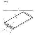
- Fig.2 depicts a perspective view showing an example overall appearance of a mobile electronic apparatus 1 according to the exemplary embodiment 1.
- the mobile electronic apparatus 1 of the present exemplary embodiment it is assumed that a main body part and a display part are combined together to form a single unit.
- the mobile electronic apparatus 1 may be of a collapsible type or a rotative bi-axial hinged type.
- the mobile electronic apparatus 1 includes a screen 10, on which to display a picture image, a bottom cover 20 and a key rubber 30 accepting key actuation.
- This key rubber is equivalent to the above mentioned elastic component 202.
- Fig.3 is a cross-sectional view taken in a direction as shown by arrows A, A to show components around the key rubber 30 of the mobile electronic apparatus 1 shown in Fig.2 .
- the cross-sectional view of Fig.3 illustrates a screen 10, a bottom cover 20, a key rubber 30, an LCD module 40, casing sections 50, 51, cover sections 60, 61, a basement 70 and a flexible substrate 80.
- the LCD module 40 is a display module including an LCD, and is equivalent to the above mentioned display part 203.
- the casing sections 50, 51 compose a casing of the mobile electronic apparatus 1.
- the basement 70 sustains a load exerted on key actuation.
- the flexible substrate 80 includes a circuit that transforms actuations performed by a user via the key rubber 30 into an electrical signal.
- a zone that is delimited by a broken line corresponds to such area, and which is herein termed a hollow section 100.
- the hollow section 100 includes a protuberance of the key rubber 30 and the flexible substrate 80. Note that Fig.3 shows a state of the mobile electronic apparatus 1 in which an impact is not exerted thereto from outside.
- Fig.4 depicts a plan view showing the casing sections 50, 51.
- the key rubber 30 is mounted in the hollow section 100 shown in Fig.4 .
- the casing section 51 is arched in shape.
- the casing section 51 need not be arched in shape, such that it may also be protuberant at its mid portion, for example, it may be frusto-conical in shape.
- a force of impact is applied to the mobile electronic apparatus 1 of the above described configuration from a direction B in Fig.2 , Fig.3 .
- the mobile electronic apparatus 1, shown in Fig.2 is shown in Fig.5 , a cross-sectional view taken along the direction indicated by arrows A, A, in a state in which a force of impact has been applied to the apparatus from the direction B.
- the subject to be protected in case the force of impact is applied from outside the mobile electronic apparatus 1 is the LCD module 40.
- the subject to be protected may also be a component vulnerable against impact, such as the screen 10 or the substrate.
- the shape of the component parts, inclusive of the casing sections 50, 51 or the cover section 60, is not be limited to that shown in the present exemplary embodiment.
- the flexible substrate 80 may also be a rigid- flexible substrate obtained by depositing an ACF (anisotropic conductive film) on a rigid substrate to unify the so deposited film to the rigid substrate.
- ACF anisotropic conductive film
- the hollow section 100 is provided within the inside of the mobile electronic apparatus 1.
- the casing bottom cover 20, casing section 51 and cover section 60
- the hollow section 100 becomes deformed under the force of impact applied from outside the mobile electronic apparatus 1.
- the key rubber 30 becomes deformed, as a result of which the force of impact acting on the LCD module 40 may be moderated to prevent the LCD module from being fractured.
- a flexible member such as a rubber component, which is soft and flaccid, is arranged within the hollow section 100, such that component parts as needed for configuring the mobile electronic apparatus 1 are arranged as the room for the flexible member to become deformed is left in the hollow section 100. This improves the packaging efficiency of the mobile electronic apparatus 1.
- the mobile electronic apparatus may further be reduced in size, thickness and weight.
- the mobile electronic apparatus has a key on its display surface.
- Fig.6 depicts a cross-sectional view showing an example case where parts of the key rubber 30 and the flexible substrate 80, such as those shown in the cross-sectional view of Fig.3 , are lacking.
- the same symbols are used to denote component parts which are the same as those shown in Fig.3 , and the corresponding explanation is dispensed with
- the hollow section 100 is composed by a void spacing and flexible components.
- a hollow section 101 may be composed by solely a void spacing. Even in such case, the bottom cover 20, a key rubber 30a, a casing section 51 and a cover section 60 become deformed to prevent the LCD module 40 from being fractured by impact applied from outside.
- the key rubber corresponds to the key rubber 30 a part of which has been removed. Since there is no key on the display surface of a mobile electronic apparatus 2 of the present exemplary embodiment, it is an elastic member shaped equivalently to the key rubber 30a that is actually used.
- Patent Literatures are to be incorporated herein by reference.
- the particular exemplary embodiments may be modified or improved within the gamut of the entire disclosure of the present invention, inclusive of claims, based on the fundamental technical concept of the invention.
- variegated combinations, substitutions or selections of the elements disclosed inclusive of various elements of the claims, exemplary embodiments or the drawings may be made within the context of the claims.
- the present invention may comprise a variety of modification or adjustments that may readily be made by those skilled in the art based on the total of the disclosures and technical concepts inclusive of the claims.
- the display system may be organic EL in place of LCD.
Landscapes
- Engineering & Computer Science (AREA)
- Computer Hardware Design (AREA)
- Theoretical Computer Science (AREA)
- General Engineering & Computer Science (AREA)
- Signal Processing (AREA)
- Human Computer Interaction (AREA)
- Physics & Mathematics (AREA)
- General Physics & Mathematics (AREA)
- Microelectronics & Electronic Packaging (AREA)
- Casings For Electric Apparatus (AREA)
- Telephone Set Structure (AREA)
- Devices For Indicating Variable Information By Combining Individual Elements (AREA)
Applications Claiming Priority (2)
| Application Number | Priority Date | Filing Date | Title |
|---|---|---|---|
| JP2011036528 | 2011-02-23 | ||
| PCT/JP2012/054313 WO2012115164A1 (ja) | 2011-02-23 | 2012-02-22 | 携帯電子機器 |
Publications (1)
| Publication Number | Publication Date |
|---|---|
| EP2680544A1 true EP2680544A1 (en) | 2014-01-01 |
Family
ID=46720939
Family Applications (1)
| Application Number | Title | Priority Date | Filing Date |
|---|---|---|---|
| EP12748962.3A Withdrawn EP2680544A1 (en) | 2011-02-23 | 2012-02-22 | Mobile electronic device |
Country Status (5)
| Country | Link |
|---|---|
| US (1) | US20130335901A1 (ja) |
| EP (1) | EP2680544A1 (ja) |
| JP (1) | JPWO2012115164A1 (ja) |
| CN (1) | CN103404115A (ja) |
| WO (1) | WO2012115164A1 (ja) |
Families Citing this family (9)
| Publication number | Priority date | Publication date | Assignee | Title |
|---|---|---|---|---|
| USD735704S1 (en) * | 2013-02-18 | 2015-08-04 | Samsung Electronics Co., Ltd. | Portable terminal |
| USD753622S1 (en) * | 2013-09-26 | 2016-04-12 | Lg Electronics Inc. | Mobile phone |
| USD767521S1 (en) * | 2014-03-14 | 2016-09-27 | Lg Electronics Inc. | Cellular phone |
| JP2016032017A (ja) * | 2014-07-29 | 2016-03-07 | Necプラットフォームズ株式会社 | 部品収容装置および電子装置 |
| USD798255S1 (en) * | 2014-09-02 | 2017-09-26 | Isaac S. Daniel | Mobile communication device with a plurality of biometric verification means |
| USD794588S1 (en) * | 2014-09-02 | 2017-08-15 | Isaac S. Daniel | Mobile communication device |
| USD794589S1 (en) * | 2014-09-02 | 2017-08-15 | Isaac S. Daniel | Mobile communication device with biometric verification means |
| USD789318S1 (en) * | 2015-04-08 | 2017-06-13 | Lg Electronics Inc. | Mobile phone |
| USD807315S1 (en) * | 2015-07-01 | 2018-01-09 | Lg Electronics Inc. | Mobile phone |
Family Cites Families (6)
| Publication number | Priority date | Publication date | Assignee | Title |
|---|---|---|---|---|
| US6031524A (en) * | 1995-06-07 | 2000-02-29 | Intermec Ip Corp. | Hand-held portable data terminal having removably interchangeable, washable, user-replaceable components with liquid-impervious seal |
| JPH11195884A (ja) * | 1997-12-26 | 1999-07-21 | Kokusai Electric Co Ltd | 携帯用電子機器 |
| JP3952567B2 (ja) * | 1998-01-05 | 2007-08-01 | 日産自動車株式会社 | 樹脂製ケース |
| JP2000069135A (ja) * | 1998-08-17 | 2000-03-03 | Sony Corp | 衝撃緩和筐体及びそれを備えた携帯型情報端末装置 |
| KR100420279B1 (ko) * | 2001-06-07 | 2004-03-02 | 삼성전자주식회사 | 전자파 발생을 최소화한 휴대용 통신 장치 |
| CN101529488B (zh) * | 2006-10-24 | 2012-10-31 | 松下电器产业株式会社 | 具有显示装置的电子设备和移动电话 |
-
2012
- 2012-02-22 US US14/001,079 patent/US20130335901A1/en not_active Abandoned
- 2012-02-22 WO PCT/JP2012/054313 patent/WO2012115164A1/ja active Application Filing
- 2012-02-22 CN CN2012800099637A patent/CN103404115A/zh active Pending
- 2012-02-22 JP JP2013501105A patent/JPWO2012115164A1/ja active Pending
- 2012-02-22 EP EP12748962.3A patent/EP2680544A1/en not_active Withdrawn
Non-Patent Citations (1)
| Title |
|---|
| See references of WO2012115164A1 * |
Also Published As
| Publication number | Publication date |
|---|---|
| WO2012115164A1 (ja) | 2012-08-30 |
| US20130335901A1 (en) | 2013-12-19 |
| JPWO2012115164A1 (ja) | 2014-07-07 |
| CN103404115A (zh) | 2013-11-20 |
Similar Documents
| Publication | Publication Date | Title |
|---|---|---|
| EP2680544A1 (en) | Mobile electronic device | |
| US8639303B2 (en) | Mobile electronic device with an enhanced antenna farm | |
| US9124676B2 (en) | Mobile electronic device with enhanced impact mitigation | |
| US8797749B2 (en) | Electronic apparatus including bumper portion protecting housing | |
| US9350840B2 (en) | Mobile electronic device with enhanced tolerance accumulator | |
| US8922980B2 (en) | Mobile electronic device with enhanced chassis | |
| US20150038199A1 (en) | Portable terminal device | |
| US20130156233A1 (en) | Mobile terminal | |
| US9143586B2 (en) | Mobile electronic device with enhanced laminate construction | |
| MX2013008183A (es) | Aparato, sistema y procedimiento de accionador sin bastidor. | |
| EP2827564A1 (en) | Portable terminal device | |
| EP2806419A1 (en) | Mobile terminal device | |
| US8115886B2 (en) | Flexible display apparatus | |
| EP2571231B1 (en) | Cushion for a folding handheld electronic device and waterproofing structure for a folding handheld electronic device | |
| JP2006293926A (ja) | 表示装置、および携帯型電子機器 | |
| JP2013205551A (ja) | 透光性パネル取付構造及び携帯型電子機器 | |
| US20220149337A1 (en) | Method for manufacturing a display device | |
| JP2010026255A (ja) | 携帯型電子機器 | |
| JP2005189512A (ja) | 電子機器における背面lcdの衝撃吸収構造および該構造を備えた電子機器 | |
| KR102606085B1 (ko) | 전자 기기 | |
| JP2011109289A (ja) | 携帯端末装置 | |
| US20060187143A1 (en) | Dual type LCD module for mobile phone | |
| US8400571B2 (en) | Television and electronic apparatus | |
| JP2006126832A (ja) | ディスプレー装置およびそれを備えた携帯電話機 | |
| JP2009130121A (ja) | 携帯型電子機器、およびその製造方法 |
Legal Events
| Date | Code | Title | Description |
|---|---|---|---|
| PUAI | Public reference made under article 153(3) epc to a published international application that has entered the european phase |
Free format text: ORIGINAL CODE: 0009012 |
|
| 17P | Request for examination filed |
Effective date: 20130911 |
|
| AK | Designated contracting states |
Kind code of ref document: A1 Designated state(s): AL AT BE BG CH CY CZ DE DK EE ES FI FR GB GR HR HU IE IS IT LI LT LU LV MC MK MT NL NO PL PT RO RS SE SI SK SM TR |
|
| DAX | Request for extension of the european patent (deleted) | ||
| STAA | Information on the status of an ep patent application or granted ep patent |
Free format text: STATUS: THE APPLICATION HAS BEEN WITHDRAWN |
|
| 18W | Application withdrawn |
Effective date: 20160229 |