EP2680415A1 - Ensemble générateur d'énergie sans noyau, magnétique à aimant permanent aux terres rares - Google Patents
Ensemble générateur d'énergie sans noyau, magnétique à aimant permanent aux terres rares Download PDFInfo
- Publication number
- EP2680415A1 EP2680415A1 EP11859132.0A EP11859132A EP2680415A1 EP 2680415 A1 EP2680415 A1 EP 2680415A1 EP 11859132 A EP11859132 A EP 11859132A EP 2680415 A1 EP2680415 A1 EP 2680415A1
- Authority
- EP
- European Patent Office
- Prior art keywords
- generator
- magnetism stopper
- rare earth
- earth permanent
- engine
- Prior art date
- Legal status (The legal status is an assumption and is not a legal conclusion. Google has not performed a legal analysis and makes no representation as to the accuracy of the status listed.)
- Withdrawn
Links
Images
Classifications
-
- H—ELECTRICITY
- H02—GENERATION; CONVERSION OR DISTRIBUTION OF ELECTRIC POWER
- H02K—DYNAMO-ELECTRIC MACHINES
- H02K7/00—Arrangements for handling mechanical energy structurally associated with dynamo-electric machines, e.g. structural association with mechanical driving motors or auxiliary dynamo-electric machines
- H02K7/18—Structural association of electric generators with mechanical driving motors, e.g. with turbines
- H02K7/1807—Rotary generators
-
- F—MECHANICAL ENGINEERING; LIGHTING; HEATING; WEAPONS; BLASTING
- F02—COMBUSTION ENGINES; HOT-GAS OR COMBUSTION-PRODUCT ENGINE PLANTS
- F02B—INTERNAL-COMBUSTION PISTON ENGINES; COMBUSTION ENGINES IN GENERAL
- F02B63/00—Adaptations of engines for driving pumps, hand-held tools or electric generators; Portable combinations of engines with engine-driven devices
- F02B63/04—Adaptations of engines for driving pumps, hand-held tools or electric generators; Portable combinations of engines with engine-driven devices for electric generators
- F02B63/042—Rotating electric generators
-
- H—ELECTRICITY
- H02—GENERATION; CONVERSION OR DISTRIBUTION OF ELECTRIC POWER
- H02K—DYNAMO-ELECTRIC MACHINES
- H02K21/00—Synchronous motors having permanent magnets; Synchronous generators having permanent magnets
- H02K21/12—Synchronous motors having permanent magnets; Synchronous generators having permanent magnets with stationary armatures and rotating magnets
- H02K21/24—Synchronous motors having permanent magnets; Synchronous generators having permanent magnets with stationary armatures and rotating magnets with magnets axially facing the armatures, e.g. hub-type cycle dynamos
-
- H—ELECTRICITY
- H02—GENERATION; CONVERSION OR DISTRIBUTION OF ELECTRIC POWER
- H02K—DYNAMO-ELECTRIC MACHINES
- H02K7/00—Arrangements for handling mechanical energy structurally associated with dynamo-electric machines, e.g. structural association with mechanical driving motors or auxiliary dynamo-electric machines
- H02K7/18—Structural association of electric generators with mechanical driving motors, e.g. with turbines
- H02K7/1807—Rotary generators
- H02K7/1815—Rotary generators structurally associated with reciprocating piston engines
Definitions
- the present invention relates to an engine-driven generator set, and more particularly to a rare earth permanent magnet coreless generator set.
- a generator stator of a conventional engine-driven generator set is mounted coaxially with an engine crankshaft, and the generator stator is mounted directly on a casing or a side cover of the engine.
- An outer rotor with a shell structure is mounted on a power output end of the crankshaft of the engine, and a shell mouth is provided toward the engine and the generator stator.
- a cooling fan is mounted on a back of a shell body of the outer rotor for cooling the generator stator, rotor, etc.
- the generator stator of the generator is located between the engine and the shell body, therefore, although an insulation space is provided between the engine and the stator, heat generated by the running generator will radiate to the generator stator and lead to technical problems such as decrease of an output efficiency of the generator, rapidly aging of an output cable of the generator due to the heat and complex maintenance of the generator stator.
- a rare earth permanent magnet coreless generator set comprising:
- a generator comprising:
- stator mounted on the generator casing, comprising disc windings and a shell made of polymer covering the disc windings;
- a first magnetism stopper mounted on the output shaft by a flat key, wherein the first magnetism stopper is provided between the stator and the generator holder for defining a suction chamber and an exhaust chamber; a first diversion tunnel communicating the suction chamber to the exhaust chamber is provided on the first magnetism stopper and is close to the output shaft;
- a second magnetism stopper mounted on the output shaft by the flat key, wherein the second magnetism stopper is provided on the stator and is away from the first magnetism stopper;
- a rib leaf mounted on the first magnetism stopper and close to the generator holder;
- an output power box mounted on the frame and electrically connected to the inverter.
- the engine is embodied as a diesel engine, a gasoline engine, a turbine, a hydraulic engine or a wind engine.
- a second diversion tunnel is provided on the second magnetism stopper and is close to the output shaft.
- the disc windings comprise radial and circumferential cross-wound copper wires.
- the first magnetism stopper and the second magnetism stopper are embodied as concave-convex discs.
- a sectional shape of each of the rare earth permanent magnets is trapezoidal, and the rare earth permanent magnets are symmetrical provided on the first magnetism stopper and the second magnetism stopper.
- the rib leaf can stir air flow in the generator, and a pressure difference is generated in a radial direction in such a manner that the air flows from the suction chamber to the exhaust chamber through the first diversion tunnel.
- a part of the heat generated by the stator is taken to the exhaust chamber for cooling, and the air flows in such a manner that transfer of the heat to an outer wall is more sufficiently provided for reducing an operating temperature of the generator and increasing an output power of the engine.
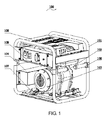
- Fig. 1 is a perspective assembly view of a rare earth permanent magnetic coreless generator set according to the preferred embodiment of the present invention.
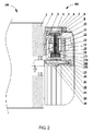
- Fig. 2 is a sectional view of the engine and the generator showed in the Fig. 1 according to the preferred embodiment of the present invention.
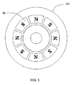
- Fig. 3 is a side view of the first magnetism stopper and the rare earth permanent magnets showed in the Fig. 2 according to the preferred embodiment of the present invention.
- a rare earth permanent magnet coreless generator set 100 comprising: a frame 101, an engine 102, a generator 103, an inverter 104, an output power box 105, a handle 106, a vibration damping cushion 107 and a cover panel 108.
- the frame 101 is made of a bent metal tube.
- the engine 102 is mounted on the frame 101 with the vibration damping cushion 107 and screw bolts.
- the engine 102 is embodied as a diesel engine. It should be noticed that the engine 102 can also be embodied as a gasoline engine, a turbine, a hydraulic engine or a wind engine.
- the generator 103 is mounted on the engine 102 by the screw bolts.
- the inverter 104 and the output power box 105 are mounted on the frame 101 by the screw bolts and are electrically connected to the generator 103 through a wire (not shown in the drawings) for stabilizing an output current.
- the handle 106 is rotatably mounted on the frame 101 for providing an overall transport.
- the cover panel 108 is provided at a top of the frame 101 for covering below components such as the engine 102.
- the engine 102 comprises an end cap 1 and an output shaft 22 rotatably provided through the end cap 1.
- the generator 103 comprises a generator holder 2, a first screw 3, a generator casing 4, a second screw 5, a third screw 6, an air deflector 7, a fourth screw 8, a stator 9, a permanent magnet clamp 10, a plurality of rare earth permanent magnets 11, a fifth screw 12, a rib leaf 13, a cooling fan 14, disc windings 15, a shell 16, a first magnetism stopper 171, a second magnetism stopper 172, a gland 19, a sixth screw 20, a flat key 21, the diesel engine output shaft 22 and a separating casing 23.
- the generator holder 2 is mounted on the end cap 1 of the engine 102 by the first screw 3.
- the generator casing 4 is substantially a ring tube mounted on the generator holder 2 by the third screws 6, wherein the stator 9 is mounted in the generator casing 4.
- the air deflector 7 is mounted on the generator casing 4 by the fourth screw 8, and forms a space for accommodating a rotor and a stator 9.
- any section along an axis of the stator 9 are substantially H-shaped, wherein the stator 9 comprises the disc windings 15 and the shell 16 made of polymer covering the disc windings 15.
- the shell 16 is utilized for mounting the disc windings 15 with polymer materials having good thermal conductivity and high strength, and forming a stable disc stator structure.
- the disc windings 15 are connected to the inverter 104 through a wire.
- the disc windings 15 comprise radial and circumferential cross-wound copper wires in such a manner that the radial copper wires effectively cut perpendicular axial magnetic field lines.
- the first magnetism stopper 171 is made of a magnetically permeable material, and is a concave-convex disc.
- the first magnetism stopper 171 is mounted on the output shaft 22 by the flat key 21, and is provided between the stator 9 and the generator holder 2.
- the first magnetism stopper 171 divides a space between the stator 9 and the generator holder 2 as a suction chamber 24 close to the stator 9 and an exhaust chamber 25 close to the generator holder 2.
- a first diversion tunnel 181 communicating the suction chamber 24 to the exhaust chamber 25 is provided on the first magnetism stopper 171 and is close to the output shaft 22.
- the rib leaf 13 is mounted on the first magnetism stopper 171 by a screw and is close to the generator holder 2, that is to say, the rib leaf 13 is provided in the exhaust chamber 25.
- the leaf rib 13 is made of a metallic or a non-metallic material and has a fan blade structure with a certain area.
- the rib leaf 13 can stir air flow in the generator 103, and a pressure difference is generated in a radial direction in such a manner that the air flows from the suction chamber 24 to the exhaust chamber 25 through the first diversion tunnel 181.
- a part of the heat generated by the stator 9 is taken to the exhaust chamber 25 for cooling, and the air flows in such a manner that transfer of the heat to an outer wall is more sufficiently provided for reducing an operating temperature of the generator 103 and increasing an output power of the engine 102.
- a structure of the second magnetism stopper 172 is similar to a structure of the first magnetism stopper 171, wherein the second magnetism stopper 172 is mounted on the output shaft 22 by the flat key 21, the separating casing 23, the gland 19 and the sixth screw 20, and is provided on the stator 9 and is away from the first magnetism stopper 171.
- a second diversion tunnel is provided on the second magnetism stopper 172 and is close to the output shaft 22.
- the cooling fan 14 is mounted on the second magnetism stopper 172 by the fifth screw 12 and is away from the permanent magnet clamp 10, and the cooling fan 14 has a similar function as the rib leaf 13.
- the rare earth permanent magnets 11 are mounted on the first magnetism stopper 171 and the second magnetism stopper 172 by the permanent magnet clamp 10 and the second screw 5, and the rare earth permanent magnets 11 correspond to the stator 9.
- the permanent magnet clamp 10 is made of a non-magnetically permeable material. Referring to Fig. 3 , a sectional shape of each of the rare earth permanent magnets 11 is trapezoidal.
- the rare earth permanent magnets 11 are symmetrical provided on the first magnetism stopper 171 and the second magnetism stopper 172, and polarities of adjacent magnets is opposite in such a manner that the magnetic field lines are more concentrated.
- the rare earth permanent magnet 11 is a permanent magnet material made of an alloy of rare earth metals and transition metals with certain procedures, and neodymium ferrum boron (NdFeB), for example, is one of the permanent magnet materials.
- the engine 102 drives the output shaft 22 to rotate in such a manner that the rare earth permanent magnets 11 rotate with the first magnetism stopper 171 and the second magnetism stopper 172.
- the disc windings 15 in the stator 9 cut the magnetic field lines for generating an electromotive force.
- the current generated by the disc winding 15 is transmitted to the inverter 104 by the wire for appropriate transformation; finally, the current is inputted into the output power box 105 for subsequent utilization.
- the above rare earth permanent magnet coreless generator set has advantages as follows:
- the rare earth permanent magnets 11 are firmly mounted on the first magnetism stopper 171 and second magnetism stopper 172;
- the stator 9 comprises the disc windings 15, and is coreless in such a manner that less heat is generated;
- the generator 103 has a high efficiency
- the generator 103 has no slot effect and has a steady speed
Landscapes
- Engineering & Computer Science (AREA)
- Power Engineering (AREA)
- Chemical & Material Sciences (AREA)
- Combustion & Propulsion (AREA)
- Mechanical Engineering (AREA)
- General Engineering & Computer Science (AREA)
- Permanent Magnet Type Synchronous Machine (AREA)
- Permanent Field Magnets Of Synchronous Machinery (AREA)
- Connection Of Motors, Electrical Generators, Mechanical Devices, And The Like (AREA)
- Motor Or Generator Cooling System (AREA)
Applications Claiming Priority (1)
| Application Number | Priority Date | Filing Date | Title |
|---|---|---|---|
| PCT/CN2011/071329 WO2012113159A1 (fr) | 2011-02-25 | 2011-02-25 | Ensemble générateur d'énergie sans noyau, magnétique à aimant permanent aux terres rares |
Publications (2)
| Publication Number | Publication Date |
|---|---|
| EP2680415A1 true EP2680415A1 (fr) | 2014-01-01 |
| EP2680415A4 EP2680415A4 (fr) | 2016-10-19 |
Family
ID=46720104
Family Applications (1)
| Application Number | Title | Priority Date | Filing Date |
|---|---|---|---|
| EP11859132.0A Withdrawn EP2680415A4 (fr) | 2011-02-25 | 2011-02-25 | Ensemble générateur d'énergie sans noyau, magnétique à aimant permanent aux terres rares |
Country Status (4)
| Country | Link |
|---|---|
| US (1) | US20130328321A1 (fr) |
| EP (1) | EP2680415A4 (fr) |
| JP (1) | JP2014511098A (fr) |
| WO (1) | WO2012113159A1 (fr) |
Families Citing this family (3)
| Publication number | Priority date | Publication date | Assignee | Title |
|---|---|---|---|---|
| CN104467243B (zh) * | 2014-12-29 | 2017-03-15 | 中国科学院电工研究所 | 一种盘式电机定子冷却结构 |
| CN110460193A (zh) * | 2019-08-09 | 2019-11-15 | 泰安阳光动力电机有限公司 | 一种发电机与油机一体式机组 |
| CN113027603A (zh) * | 2021-04-25 | 2021-06-25 | 江苏常发农业装备股份有限公司 | 一种发电机组 |
Family Cites Families (30)
| Publication number | Priority date | Publication date | Assignee | Title |
|---|---|---|---|---|
| US4451749A (en) * | 1981-09-11 | 1984-05-29 | Nippondenso Co., Ltd. | AC Generator |
| US4484097A (en) * | 1982-06-08 | 1984-11-20 | Nippondenso Co., Ltd. | Flat coil for an electric machine |
| JPS6039336A (ja) * | 1983-08-12 | 1985-03-01 | Nippon Denso Co Ltd | 扁平型回転電機の冷却構造 |
| DE3510228A1 (de) * | 1985-03-21 | 1986-09-25 | Robert Bosch Gmbh, 7000 Stuttgart | Buerstenlose axialluftspalt-synchronmaschine |
| JP3612807B2 (ja) * | 1995-07-28 | 2005-01-19 | 株式会社デンソー | ウォータポンプ一体型車両用回転電機 |
| US5744896A (en) * | 1996-05-21 | 1998-04-28 | Visual Computing Systems Corp. | Interlocking segmented coil array |
| US5962942A (en) * | 1996-05-31 | 1999-10-05 | The Turbo Genset Company Limited | Rotary electrical machines |
| US6064121A (en) * | 1998-02-27 | 2000-05-16 | Hamilton Sundstrand Corporation | Axially compact generator set and refrigeration system employing the same |
| US6404097B1 (en) * | 1998-04-23 | 2002-06-11 | The Turbo Genset Company, Ltd. | Rotary electrical machines |
| US5977684A (en) * | 1998-06-12 | 1999-11-02 | Lin; Ted T. | Rotating machine configurable as true DC generator or motor |
| KR20000012296A (ko) * | 1998-11-23 | 2000-03-06 | 이정훈 | 휴대용 소형 판형 발전기 |
| JP2000328956A (ja) * | 1999-05-20 | 2000-11-28 | Honda Motor Co Ltd | エンジン発電機 |
| JP2002262495A (ja) * | 2001-02-28 | 2002-09-13 | Isuzu Ceramics Res Inst Co Ltd | 磁石式発電機 |
| JP2004173343A (ja) * | 2002-11-18 | 2004-06-17 | Fuji Heavy Ind Ltd | エンジン発電機 |
| CA2436369A1 (fr) * | 2003-08-05 | 2005-02-05 | Tecobim Inc. | Alternateur a aimants permanents |
| JP4543709B2 (ja) * | 2004-03-09 | 2010-09-15 | 株式会社エクォス・リサーチ | アキシャルギャップ回転電機 |
| JP2006188982A (ja) * | 2005-01-06 | 2006-07-20 | Yamaha Motor Co Ltd | エンジン式発電機 |
| TWM299219U (en) * | 2005-12-02 | 2006-10-11 | Ming-Huang Lin | Improved electricity generator structure |
| KR100870738B1 (ko) * | 2007-01-25 | 2008-11-26 | 태창엔이티 주식회사 | 에이에프피엠 코어리스형 멀티 발전기 및 모터 |
| JP4940469B2 (ja) * | 2007-01-31 | 2012-05-30 | A−Wingインターナショナル株式会社 | 発電機 |
| JP2008245356A (ja) * | 2007-03-26 | 2008-10-09 | Moriyama Denki Seisakusho:Kk | アキシャルギャップ型エンジン駆動発電機 |
| TW200903956A (en) * | 2007-07-05 | 2009-01-16 | Chuan-Sheng Chen | Thin flat generator |
| JP5033552B2 (ja) * | 2007-09-14 | 2012-09-26 | 信越化学工業株式会社 | アキシャルギャップ型コアレス回転機 |
| CN201273212Y (zh) * | 2008-08-28 | 2009-07-15 | 上海扬科发动机进出口有限公司 | 一种小功率风冷二冲程汽油变频发电机组 |
| JP2010110166A (ja) * | 2008-10-31 | 2010-05-13 | Daikin Ind Ltd | アキシャルギャップ型回転電機 |
| CN201288604Y (zh) * | 2008-11-24 | 2009-08-12 | 济南吉美乐电源技术有限公司 | 小型化柴油发电机组 |
| CN101873029B (zh) * | 2009-04-23 | 2014-10-22 | 深圳市安托山特种机电有限公司 | 一种无铁芯永磁柴油发电机 |
| CN101705864B (zh) * | 2009-04-27 | 2012-01-04 | 上海扬科进出口有限公司 | 一种汽油发电机 |
| US20130049512A1 (en) * | 2011-08-26 | 2013-02-28 | Undustry-Academic Cooperation Foundation Of Kyungnam University | Axial flux permanent magnet synchronous generator and motor |
| JP2013058658A (ja) * | 2011-09-09 | 2013-03-28 | Seiko Epson Corp | 電磁コイル、コアレス電気機械装置、移動体、ロボット、及び、電磁コイルの製造方法 |
-
2011
- 2011-02-25 JP JP2013554775A patent/JP2014511098A/ja active Pending
- 2011-02-25 WO PCT/CN2011/071329 patent/WO2012113159A1/fr active Application Filing
- 2011-02-25 EP EP11859132.0A patent/EP2680415A4/fr not_active Withdrawn
- 2011-02-25 US US14/000,180 patent/US20130328321A1/en not_active Abandoned
Also Published As
| Publication number | Publication date |
|---|---|
| WO2012113159A1 (fr) | 2012-08-30 |
| EP2680415A4 (fr) | 2016-10-19 |
| JP2014511098A (ja) | 2014-05-01 |
| US20130328321A1 (en) | 2013-12-12 |
Similar Documents
| Publication | Publication Date | Title |
|---|---|---|
| CN105305749B (zh) | 定子无铁心Halbach永磁阵列轴向磁通电机 | |
| CN202034855U (zh) | 一种同步发电机永磁转子的混合式冷却散热结构 | |
| CN101873043A (zh) | 异步起动永磁同步潜油泵电动机 | |
| HUE026324T2 (en) | Electric machine with reduced weight design in magnetically active parts | |
| CN101127469A (zh) | 一种永磁发电机的冷却系统 | |
| EP2680415A1 (fr) | Ensemble générateur d'énergie sans noyau, magnétique à aimant permanent aux terres rares | |
| CN111614220A (zh) | 低转矩脉动高速轴向磁通表贴式永磁电机 | |
| CN107508440B (zh) | 一种轴向多单元定子电励磁双极性感应子电机 | |
| CN208386261U (zh) | 一种永磁直驱电机 | |
| CN205846905U (zh) | 冷藏车用稀土永磁同步发电机 | |
| CN109347222A (zh) | 一种lng泵用低温高速永磁电机设计方法及电机结构 | |
| Li et al. | Assessment of high-speed multi-megawatt electric machines | |
| CN113162297A (zh) | 一种防爆电动机 | |
| CN202004590U (zh) | 稀土永磁无铁芯发电机组 | |
| CN106803710A (zh) | 一种体积超小高功率密度永磁外转子电机装置 | |
| CN102386732A (zh) | 一种嵌套式低速外转子永磁电机 | |
| CN105790467A (zh) | 混合励磁盘式电机 | |
| CN206727858U (zh) | 一种体积超小高功率密度永磁外转子电机装置 | |
| CN112260505A (zh) | 一种复合式同心双端口双动力电动机 | |
| CN104917349A (zh) | 新能源汽车专用助力转向高效高可靠自冷永磁同步电机 | |
| CN205336003U (zh) | 一种具有新型永磁体转子磁路的永磁发电机 | |
| CN208904781U (zh) | 一种用于提高电机散热能力的定子结构 | |
| CN201336624Y (zh) | 一种轴向电机结构 | |
| CN215817867U (zh) | 一种三相自启动永磁同步电机 | |
| CN108696086B (zh) | 一种径向磁通电机 |
Legal Events
| Date | Code | Title | Description |
|---|---|---|---|
| PUAI | Public reference made under article 153(3) epc to a published international application that has entered the european phase |
Free format text: ORIGINAL CODE: 0009012 |
|
| 17P | Request for examination filed |
Effective date: 20130826 |
|
| AK | Designated contracting states |
Kind code of ref document: A1 Designated state(s): AL AT BE BG CH CY CZ DE DK EE ES FI FR GB GR HR HU IE IS IT LI LT LU LV MC MK MT NL NO PL PT RO RS SE SI SK SM TR |
|
| DAX | Request for extension of the european patent (deleted) | ||
| RA4 | Supplementary search report drawn up and despatched (corrected) |
Effective date: 20160921 |
|
| RIC1 | Information provided on ipc code assigned before grant |
Ipc: F02B 63/04 20060101ALI20160915BHEP Ipc: H02K 9/04 20060101ALI20160915BHEP Ipc: H02K 21/12 20060101AFI20160915BHEP Ipc: H02K 7/18 20060101ALI20160915BHEP Ipc: H02K 21/24 20060101ALI20160915BHEP |
|
| STAA | Information on the status of an ep patent application or granted ep patent |
Free format text: STATUS: THE APPLICATION IS DEEMED TO BE WITHDRAWN |
|
| 18D | Application deemed to be withdrawn |
Effective date: 20170421 |