EP2679893A1 - Beleuchtungsvorrichtung - Google Patents
Beleuchtungsvorrichtung Download PDFInfo
- Publication number
- EP2679893A1 EP2679893A1 EP12749517.4A EP12749517A EP2679893A1 EP 2679893 A1 EP2679893 A1 EP 2679893A1 EP 12749517 A EP12749517 A EP 12749517A EP 2679893 A1 EP2679893 A1 EP 2679893A1
- Authority
- EP
- European Patent Office
- Prior art keywords
- installation cover
- illumination
- main body
- illumination panel
- illumination device
- Prior art date
- Legal status (The legal status is an assumption and is not a legal conclusion. Google has not performed a legal analysis and makes no representation as to the accuracy of the status listed.)
- Granted
Links
Images


Classifications
-
- F—MECHANICAL ENGINEERING; LIGHTING; HEATING; WEAPONS; BLASTING
- F21—LIGHTING
- F21V—FUNCTIONAL FEATURES OR DETAILS OF LIGHTING DEVICES OR SYSTEMS THEREOF; STRUCTURAL COMBINATIONS OF LIGHTING DEVICES WITH OTHER ARTICLES, NOT OTHERWISE PROVIDED FOR
- F21V19/00—Fastening of light sources or lamp holders
- F21V19/001—Fastening of light sources or lamp holders the light sources being semiconductors devices, e.g. LEDs
- F21V19/003—Fastening of light source holders, e.g. of circuit boards or substrates holding light sources
-
- F—MECHANICAL ENGINEERING; LIGHTING; HEATING; WEAPONS; BLASTING
- F21—LIGHTING
- F21V—FUNCTIONAL FEATURES OR DETAILS OF LIGHTING DEVICES OR SYSTEMS THEREOF; STRUCTURAL COMBINATIONS OF LIGHTING DEVICES WITH OTHER ARTICLES, NOT OTHERWISE PROVIDED FOR
- F21V19/00—Fastening of light sources or lamp holders
-
- F—MECHANICAL ENGINEERING; LIGHTING; HEATING; WEAPONS; BLASTING
- F21—LIGHTING
- F21S—NON-PORTABLE LIGHTING DEVICES; SYSTEMS THEREOF; VEHICLE LIGHTING DEVICES SPECIALLY ADAPTED FOR VEHICLE EXTERIORS
- F21S8/00—Lighting devices intended for fixed installation
- F21S8/04—Lighting devices intended for fixed installation intended only for mounting on a ceiling or the like overhead structures
-
- F—MECHANICAL ENGINEERING; LIGHTING; HEATING; WEAPONS; BLASTING
- F21—LIGHTING
- F21Y—INDEXING SCHEME ASSOCIATED WITH SUBCLASSES F21K, F21L, F21S and F21V, RELATING TO THE FORM OR THE KIND OF THE LIGHT SOURCES OR OF THE COLOUR OF THE LIGHT EMITTED
- F21Y2105/00—Planar light sources
-
- F—MECHANICAL ENGINEERING; LIGHTING; HEATING; WEAPONS; BLASTING
- F21—LIGHTING
- F21Y—INDEXING SCHEME ASSOCIATED WITH SUBCLASSES F21K, F21L, F21S and F21V, RELATING TO THE FORM OR THE KIND OF THE LIGHT SOURCES OR OF THE COLOUR OF THE LIGHT EMITTED
- F21Y2115/00—Light-generating elements of semiconductor light sources
- F21Y2115/10—Light-emitting diodes [LED]
- F21Y2115/15—Organic light-emitting diodes [OLED]
-
- H—ELECTRICITY
- H10—SEMICONDUCTOR DEVICES; ELECTRIC SOLID-STATE DEVICES NOT OTHERWISE PROVIDED FOR
- H10K—ORGANIC ELECTRIC SOLID-STATE DEVICES
- H10K2102/00—Constructional details relating to the organic devices covered by this subclass
- H10K2102/301—Details of OLEDs
- H10K2102/311—Flexible OLED
-
- H—ELECTRICITY
- H10—SEMICONDUCTOR DEVICES; ELECTRIC SOLID-STATE DEVICES NOT OTHERWISE PROVIDED FOR
- H10K—ORGANIC ELECTRIC SOLID-STATE DEVICES
- H10K50/00—Organic light-emitting devices
- H10K50/80—Constructional details
- H10K50/84—Passivation; Containers; Encapsulations
Definitions
- the present invention relates to an illumination device, and in particular relates to an illumination device provided with a sheet-shaped illumination panel.
- Japanese Patent Laid-Open No. 2004-055535 discloses an illumination device which is provided with an organic EL (OLED: Organic Light Emitting Diode) as the illumination panel.
- the illumination panel In the illumination device of Japanese Patent Laid-Open No. 2004-055535 (PTD 1), the illumination panel (OLED) is formed into a sheet shape.
- the sheet-shaped illumination panel is installed on an obverse face of a main body (supporting body).
- the sheet-shaped illumination panel shapes in accordance with the superficial shape of the main body and thereafter is installed on the obverse face of the main body through the use of an adhesive agent, a clip or the like.
- An object of the present invention is to provide an illumination device including a sheet-shaped illumination panel and capable of achieving desired light distribution characteristics of the illumination panel.
- the illumination device includes a sheet-shaped, flexible illumination panel including on its surface a light emitting face, the light emitting face being configured to emit light when supplied with electrical power; a main body including a mounting face whereon the illumination panel is to be mounted; and an installation cover which to be installed on the main body and including a pressing region pressing the light emitting face of the illumination panel against the mounting face of the main body.
- the illumination device including a sheet-shaped illumination panel and capable of achieving desired light distribution characteristics of the illumination panel.
- FIG. 1 is a perspective view illustrating an illumination device 100 according to the present embodiment in an exploded state (prior to assembly).
- Illumination device 100 includes a main body 10, an installation cover 20 and an illumination panel 30.
- installation cover 20 is installed on main body 10, sandwiching both main body 10 and illumination panel 30 (the details will be given later).
- Fig. 2 is a cross sectional view taken along a line II-II in Fig. 1
- Fig. 3 is a cross sectional view taken along a line III-III in Fig. 1
- main body 10 is formed into a plate shape, and includes ends 11 to 14 and a mounting face 15.
- Main body 10 can be fixed on a ceiling (not shown), a wall surface (not shown) or the like through the intermediary of a rear face (opposite to mounting face 15).
- Main body 10 is made of, for example, aluminum or stainless steel through a pressing operation or a cutting operation.
- the thickness of main body 10 is, for example, from 2 cm to 10 cm.
- Main body 10 is disposed with an annular groove 16 (see Figs. 1 to 3 ) having a predetermined depth along a peripheral edge of mounting face 15. To be described in detail hereinafter, the shape of annular groove 16 fits with the shape of an embedding portion 23 (see Figs. 1 and 4 ) disposed on installation cover 20. When illumination device 100 is in the assembled state, embedding portion 23 of installation cover 20 is embedded in annular groove 16 of main body 10.
- two cutouts 19 are carved side by side at predetermined positions on mounting face 15.
- a pair of electrical contacts 41 (first electrical contact) are disposed inside cutouts 19, respectively. Electrical contacts 41 are positioned in such a way that they can have a contact with electrical contacts 42 (see Fig. 6 ) of illumination panel 30 when illumination panel 30 is installed on main body 10.
- electrical contacts 41 disposed inside cutouts 19 may be fixed therein with a portion thereof protruding out of mounting face 15 like a plate spring. According to this configuration, when illumination panel 30 is installed on main body 10, a good electrical connection is achieved between electrical contacts 42 (see Fig. 6 ) of illumination panel 30 and electrical contacts 41 of main body 10. Electrical contacts 41 penetrate through main body 10 (see Fig. 3 ), and are connected to a predetermined power source (not shown).
- two supporting units 18 are disposed side by side at end 11 and end 12 facing each other, respectively.
- An L-shaped retaining member 17 is rotatably installed at supporting unit 18.
- a biasing unit such as a coil spring or the like is built inside supporting unit 18. Due to the action from the biasing unit such as a coil spring or the like, retaining member 17 installed at supporting unit 18 is biased to rotate toward mounting face 15 in the direction of an arrow AR2 (see Fig. 2 ).
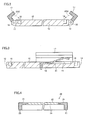
- Fig. 4 is a cross sectional view taken along a line IV-IV in Fig. 1 .
- installation cover 20 includes a plate member 21 and embedding portion 23.
- Embedding portion 23 is erected circularly around the outer periphery of plate member 21.
- the shape of embedding portion 23 fits with the shape of annular groove 16 (see Fig. 1 ) disposed on main body 10.
- the inner peripheral side of plate member 21 is disposed with a rectangular transparent plate 22 (transparent region) made of glass, acryl resin or the like.
- the thickness of transparent plate 22 is, for example, from 2 mm to 3 mm.
- the rear face (where embedding portion 23 is erected) of transparent plate 22 defines a pressing region 25.
- the surface shape of pressing region 25 (the shape of the rear face of transparent plate 22) fits with the surface shape of mounting face 15.
- Fig. 5 is a top view of illumination panel 30, and Fig. 6 is a bottom view of illumination panel 30.
- Illumination panel 30 is formed into a shape of a flexible sheet (see Figs. 1 , 5 and 6 ).
- the thickness of illumination panel 30 is, for example, about 1 mm.
- a sheet represents a planar sheet having a thickness from about 0.5 mm to about 10 mm, preferably having a substantially uniform thickness from about 0.5 mm to about 1 mm, and also includes such a sheet of a thickness as those referred to as a film sheet or a thin-plate sheet.
- the rectangular light emitting face 33 which emits light when supplied with electrical power is formed on an obverse face 31 of illumination panel 30.
- Light emitting face 33 may be constructed from, for example, organic EL (OLED: Organic Light Emitting Diode) elements.
- a rear face 32 of illumination panel 30 is disposed with a pair of electrical contacts 42 (second electrical contact) for supplying electrical power to light emitting face 33.
- light emitting face 33 is constructed from organic EL elements
- electrical power is supplied to both sides of an organic light emitting layer inside light emitting face 33.
- the organic light emitting layer emits visible light.
- a transparent electrode layer (such as ITO) is disposed on the organic light emitting layer at the side of light emitting face 33 (the side of obverse face 31), and the transparent electrode layer is sealed by a sealing layer.
- An electrode layer for example an aluminum electrode layer configured to reflect the emitted light, is disposed underneath the organic light emitting layer (at the side of rear face 32). Underneath the electrode layer (the side of rear face 32), a base layer is disposed.
- the electrode layers on both sides of the organic light emitting layer are wired, according to a predetermined pattern, to the pair of electrical contacts 42 disposed on rear face 32, respectively.
- Fig. 7 is a perspective view illustrating illumination device 100 in an assembled state (after being assembled).
- main body 10 and installation cover 20 are arranged opposite to each other, sandwiching illumination panel 30 therebetween (see Figs. 1 and 7 ).
- Retaining member 17 of main body 10 is rotated in the direction opposite to arrow AR2 (see Fig. 2 ) so as to be erected.
- Retaining member 17 may be kept at an erected state against the biasing force of a coil spring or the like through hooking by using, for example, a latch mechanism (not shown).
- illumination device 100 As illustrated in Fig. 7 is obtained.
- electrical power is supplied to light emitting face 33 of illumination panel 30 from an external power source (not shown) through the intermediary of electrical contacts 41 (see Fig. 1 ) disposed on main body 10 and electrical contacts 42 (see Fig. 6 ) disposed on illumination panel 30.
- electrical contacts 41 see Fig. 1
- electrical contacts 42 see Fig. 6
- retaining member 17 is rotated in the direction opposite to arrow AR2. While retaining member 17 is in the erected state according to the hooking by the latch mechanism, illumination panel 30 is installed on main body 10. Thereafter, the hooking by the latch mechanism is released, and illumination panel 30 is fixed on main body 10 by a biasing force in the direction of arrow AR2 by a coil spring or the like.
- the approach of installing illumination panel 30 on main body 10 is not limited to that illustrated in Fig. 2 and the like as mentioned in the above, and it is acceptable to adopt a configuration using a retaining member 17A as illustrated in Fig. 8 to do the same.
- a tip end 17T of retaining member 17A is made inclined so as to accept embedding portion 23 of installation cover 20.
- the sheet-shaped illumination panel 30 may bend in the direction of gravity due to initial distortions (such as a warp or the like resulting from manufacture or transportation) and/or due to the weight (dead weight) of illumination panel 30 itself according to an installation manner thereof.
- illumination device 100 of the present embodiment light emitting face 33 of illumination panel 30 is pressed against mounting face 15 by pressing region 25 of installation cover 20.
- pressing region 25 and mounting face 15 are sandwiched by pressing region 25 and mounting face 15, and thereby the shape thereof is retained.
- the sheet-shaped illumination panel is installed on the obverse face of the main body (supporting body).
- One face of the sheet-shaped illumination panel in PTD 1 is in contact with the main body, and the other face thereof is not in contact with any members but exposed as the light emitting face (the so-called "single face-contacting installation structure").
- the illumination panel may bend due to its dead weight. Since the illumination device in PTD 1 adopts the so-called single face-contacting installation structure, the bending of the illumination panel remains even after the installation.
- the retaining members for pre-installing the illumination panel on the main body (supporting body) are designed to have a predetermined distance therebetween.
- both ends of the illumination panel each is disposed preliminarily with a clip or the like.
- the distance between the retaining members may not fit with the distance between the clips disposed at both ends of the illumination panel.
- manufacturing error is easy to occur.
- the distance between the retaining members is different from the distance between the clips, such problem may occur that the illumination panel may have to be crinkled in order to be installed on the main body.
- illumination panel 30 is fixed through the way of being sandwiched by main body 10 and installation cover 20. Even in the case where illumination panel 30 is manufactured with dimensions different from the initially designed dimensions along, for example, the longitudinal direction, since illumination panel 30 is being fixed against main body 10 and installation cover 20 according to the pressing from both the obverse face and the rear face, no crinkles will occur. Even at this viewpoint, it is possible for illumination device 100 to achieve the desired light distribution characteristics.
- retaining member 17 and supporting unit 18 are installed at positions deviated 90° from the positions illustrated in Fig. 1 .
- the installation positions of retaining member 17 and supporting unit 18 may be at the positions illustrated in Fig. 1 (retaining member 17 and supporting unit 18 are configured to be installed on ends 11 and 12) or may be at the positions illustrated in Figs. 9 and 10 (retaining member 17 and supporting unit 18 are configured to be installed on ends 13 and 14).
- main body 10 is fixed on ceiling 50 through bolts and nuts or the like. Thereafter, illumination panel 30 is mounted on pressing region 25 of installation cover 20, with light emitting face 33 facing downward. Under this condition, as illustrated by an arrow AR3, embedding portion 23 of installation cover 20 is embedded into annular groove 16 of main body 10. At this time, as illustrated in Fig. 9 , a warp may occur in the sheet-shaped illumination panel 30 due to the residual stress or the like resulting from the manufacture.
- illumination panel 30 is fixed through the way of being sandwiched by main body 10 and installation cover 20. Even though a warp has occurred on illumination panel 30, when illumination device 100 is in the assembled state, illumination panel 30 will be pressed by pressing region 25 and mounting face 15 and thereby the warp will be corrected. Light emitting face 33 will be shaped (corrected) in correspondence with the shapes of mounting face 15 and pressing region 15 (transparent plate 22). As a result, it is possible to keep light emitting face 33 in the initially designed shape, making it possible to achieve desired light distribution characteristics.
- Fig. 11 is a perspective view illustrating an installation cover 20A used in an illumination device according to a first modification of the above Embodiment 1.
- a plurality of through holes 22A may be disposed in an inner periphery of plate member 21.
- installation cover 20A does not include transparent plate 22.
- Each through hole 22A is formed by perforating plate member 21, and through holes 22A are arranged in a lattice pattern, for example.
- Pressing region 25 is defined by the remaining part without being perforated on the rear face of plate member 21. Thereby, pressing region 25 of the present modification is formed into the lattice pattern defmed by the shape of each through hole 22A. For the purpose of correcting a warp on illumination panel 30, it is desirable that pressing region 25 is arranged uniformly relative to the entire part of light emitting face 33, like installation cover 20A having the lattice-patterned portion according to the present modification.
- pressing region 25 may not have to be arranged uniformly relative to the entire part of light emitting face 33; it is acceptable that pressing region 25 is formed somewhat non-uniformly as long as pressing region 25 can press a part of light emitting face 33 so as to correct the warp on illumination panel 30 to some extent, and it is also acceptable that pressing region 25 is formed into the other shapes from the viewpoint of design or the like.
- Fig. 12 is a plan view illustrating an installation cover 20B used in an illumination device according to a second modification of the above Embodiment 1.
- wires 22B are disposed in the inner periphery of plate member 21.
- installation cover 20B does not include transparent plate 22.
- wires 22B are disposed in a lattice pattern, for example, as illustrated in Fig. 12 .
- Pressing region 25 is defined by a rear face of wires 22B.
- pressing region 25 (wires 22B) may be formed into the other shapes from the viewpoint of design on a condition that it is possible for it to press a part of light emitting face 33.
- light emitting face 33 (see Fig. 1 ) of illumination panel 30 (see Fig. 1 ) is exposed directly through the spaces between wires 22B.
- a part of light emitting face 33 is pressed by pressing region 25 against mounting face 15 through the lattice pattern, it is possible for light emitting face 33 to keep the initially designed shape.
- light emitting face 33 it is also possible for light emitting face 33 to achieve the initially designed light distribution characteristics without causing the problem that the intensity of light from light emitting face 33 may become irregular (uneven) depending on the direction of illumination.
- Fig. 13 is a cross sectional view illustrating an illumination device according to a third modification of the above Embodiment 1.
- An installation cover 20C used in the illumination device according to the present modification has a part thereof (herein, one end of installation cover 20C) preliminarily fixed at main body 10 through the intermediary of a supporting unit 18A.
- Installation cover 20C is rotatable about supporting unit 18A.
- Embedding portion 23 at the other end of installation cover 20C can be embedded into annular groove 16, as illustrated by an arrow AR4.
- preliminary (permanent) installation of installation cover 20C on main body 10 makes it possible to improve the working convenience of a worker in installing or replacing illumination panel 30.
- a restraint member 24 may be disposed between installation cover 20C1 and main body 10. Restraint member 24 is constructed by joining two thin plate members. Restraint member 24 may be a string-like member. As illustrated in Fig. 14 , restraint member 24 may be disposed along the side surfaces of main body 10 and installation cover 20C1. Restraint member 24 is configured to restrain installation cover 20C1 from being opened too wide from main body 10 when installation cover 20C1 is rotated about supporting unit 18A. Due to the disposition of restraint member 24, the angle of installation cover 20C1 relative to main body 10 can be kept at a predetermined value, which makes it possible to easily mount illumination panel 30 onto installation cover 20C1.
- a restraint member 24A may be disposed as a unit for restraining installation cover 20C2 from being opened too wide from main body 10. Restraint member 24A is disposed at the end of installation cover 20C2 where installation cover 20C2 is installed on supporting unit 18A. As illustrated in Fig 17 , as installation cover 20C2 is rotated about supporting unit 18A, restraint member 24A contacts ceiling 50, which thereby restrains installation cover 20C2 from being opened too wide from main body 10. According to this configuration, it is also possible to obtain the same effects as the abovementioned restraint member 24 (see Figs. 14 and 15 ).
- Fig. 18 is a bottom view of an illumination panel 30A used in an illumination device according to a fourth modification of the above Embodiment 1.
- Fig. 18 corresponds to Fig. 6 in the above Embodiment 1.
- a pair of electrical contacts 42 are disposed on rear face 32 of illumination panel 30 by extending with a predetermined length along the peripheral edges thereof.
- electrical contacts 41 (not shown) disposed on main body 10 (not shown) are arranged at predetermined positions on mounting face 15 (not shown) in accordance with the positions of electrical contacts 42. Since electrical contacts 42 are sufficiently long relative to electrical contacts 41 on mounting face 15, even in the case where illumination panel 30A is fixed with a deviation to some extent, it is possible to obtain a good electrical connection between electrical contacts 41 and electrical contacts 42.
- Fig. 19 is a bottom view of an illumination panel 30B used in an illumination device according to a fifth modification of the above Embodiment 1.
- Fig. 19 corresponds to Fig. 6 in the above Embodiment 1.
- a pair of positive electrical contacts 42 (42A) are disposed on rear face 32 of illumination panel 30B by extending with a predetermined length along the opposing peripheral edges thereof.
- a pair of negative electrical contacts 42 are disposed on rear face 32 of illumination panel 30B by extending with a predetermined length along the other opposing peripheral edges thereof. It is acceptable that illumination panel 30B has two positive electrical contacts 42 (42A) and two negative electrical contacts 42 (42B) disposed on rear face 32.
- electrical contacts 41 (not shown) disposed on main body 10 (not shown) are arranged at predetermined positions on mounting face 15 (not shown) in respective accordance with the positions of positive electrical contacts 42 (42A) and the position of negative electrical contacts 42 (42B). Since positive electrical contacts 42 (42A) and negative electrical contacts 42 (42B) are sufficiently long relative to electrical contacts 41 on mounting face 15, even in the case where illumination panel 30A is fixed with a deviation to some extent, it is possible to obtain a good electrical connection from electrical contacts 41 to electrical contacts 42 (42A) and to electrical contacts 42 (42B).
- FIG. 20 is a bottom view illustrating an installation cover 20D used in the illumination device according to the present modification.
- Fig. 21 is a cross sectional view taken along a line XXI-XXI in Fig. 20.
- Fig. 22 is a bottom view illustrating a state where illumination panel 30 is mounted on pressing region 25 of installation cover 20D.
- Fig. 23 is a cross sectional view taken along a line XXIII-XXIII in Fig. 22 .
- prefixing portions 26 are disposed at a peripheral edge (herein, the top end of embedding portion 23 in the erecting direction) of installation cover 20D.
- Prefixing portions 26 of installation cover 20D are disposed side by side on one end of the annular-shaped embedding portion 23 in rectangular form, extending with a predetermined length so as to have a partial overlap with pressing region 25 in planar view.
- Each prefixing portion 26 is separated from pressing region 25 by a distance L1 (see Fig. 21 ). It should be noted that along with the disposition of prefixing portion 26, the shape of annular groove 16 (not shown) disposed in mounting face 15 (not shown) of main body 10 (not shown) may be changed in accordance with the shape of prefixing portion 26.
- each end portion (having a thickness L2) of illumination panel 30 is inserted between prefixing portions 26 and pressing region 25 (thickness L2 ⁇ distance L1). Thereby, illumination panel 30 is prefixed relative to installation cover 20D. Due to the prefixing, illumination panel 30 is prevented from dropping (being disengaged) away from installation cover 20D, which makes it possible to improve the working convenience of a worker in installing or replacing illumination panel 30.
- FIG. 24 is a bottom view illustrating an installation cover 20E used in the illumination device according to the present modification.
- Fig. 25 is a cross sectional view taken along a line XXV-XXV in Fig. 24 .
- Fig. 26 is a bottom view illustrating a state where illumination panel 30 is mounted on pressing region 25 of installation cover 20E.
- Fig. 27 is a cross sectional view taken along a line XXVII-XXVII in Fig. 26 .
- prefixing portions 26 are disposed at peripheral edges (herein, the top ends of embedding portion 23 in the erecting direction) of installation cover 20E.
- Two prefixing portions 26 of installation cover 20E are disposed side by side on each of two opposing ends of the annular-shaped embedding portion 23 in rectangular form, extending with a predetermined length so as to have a partial overlap with pressing region 25 in planar view.
- Each prefixing portion 26 is separated from pressing region 25 by distance L1 (see Fig. 25 ). It should be noted that along with the disposition of prefixing portion 26, the shape of annular groove 16 (not shown) disposed on mounting face 15 (not shown) of main body 10 (not shown) may be changed in accordance with the shape of prefixing portion 26.
- each end portion (having thickness L2) of illumination panel 30 is inserted between prefixing portions 26 and pressing region 25 (thickness L2 ⁇ distance L1).
- illumination panel 30 is prefixed relative to installation cover 20E. Due to the prefixing, illumination panel 30 is prevented from dropping (being disengaged) away from installation cover 20E, which makes it possible to improve the working convenience of a worker in installing or replacing illumination panel 30.
- prefixing portion 26 may be configured as being rotatable in the direction of an arrow in Fig. 28 about the top end of embedding portion 23 in the erecting direction toward illumination panel 30.
- illumination panel 30 In mounting illumination panel 30 on the installation cover (installation cover 20E), by erecting prefixing portions 26 (to the state illustrated in Fig. 28 ), it is possible to easily mount illumination panel 30 on the installation cover (installation cover 20E). After illumination panel 30 is mounted, illumination panel 30 is prefixed by rotating prefixing portion 26 toward illumination panel 30.
- prefixing portion 26 may be configured as being rotatable about the top end of embedding portion 23 in the erecting direction toward illumination panel 30.
- FIG. 29 is a bottom view illustrating an installation cover 20F used in the illumination device according to the present modification.
- Fig. 30 is a perspective view illustrating a portion nearby a guide member 27 (the detail thereof will be described hereinafter) of installation cover 20F.
- Fig. 31 is a bottom view illustrating an illumination panel 30C used in the illumination device according to the present modification.
- guide member 27 (first guide portion) is formed at a peripheral edge (herein, a corner of the annular-shaped embedding portion 23 in rectangular form) of installation cover 20F.
- Guide member 27 is formed into a substantially triangular prism shape by extending from the top end of embedding portion 23 in the erecting direction to reach plate member 21 (in the direction orthogonal to the plane of paper in Fig. 29 ) and bulging from the corner of embedding portion 23 toward pressing region 25.
- a guide member 37 (first guide portion) is formed at a peripheral edge (herein, a corner of illumination panel 30C in rectangular form) of illumination panel 30C.
- Guide member 37 is formed by chamfering the corner.
- Guide member 37 fits with guide member 27 of installation cover 20F in shape and position.
- illumination panel 30C is mounted on pressing region 25 of installation cover 20F in such a way that guide member 27 and guide member 37 fit each other (i.e., face each other). Illumination panel 30C cannot be mounted on pressing region 25 of installation cover 20F from another geometric angle (phase). Thereby, the so-called reverse insertion of illumination panel 30C into installation cover 20F is prevented, which in turn prevents electrical contacts 41 (not shown) on main body 10 (not shown) from being connected to electrical contacts 42 on illumination panel 30C in wrong polarity, making it possible to improve the working convenience of a worker in installing or replacing illumination panel 30C.
- FIG. 32 is a bottom view illustrating an installation cover 20G used in the illumination device according to the present modification.
- Fig. 33 is a bottom view illustrating an illumination panel 30D used in the illumination device according to the present modification.
- guide member 27 (second guide portion) is formed at a peripheral edge (herein, one end of the annular-shaped embedding portion 23 in rectangular form) of installation cover 20G.
- Guide member 27 is formed into a cuboid shape by extending from the top end of embedding portion 23 in the erecting direction to reach plate member 21 (in the direction orthogonal to the plane of paper in Fig. 32 ) and bulging from one end of embedding portion 23 toward pressing region 25.
- guide member 37 (first guide member) is formed at a peripheral edge (herein, one end of illumination panel 30D in rectangular form) of illumination panel 30D.
- Guide member 37 is formed by cutting out a part of the edge, fitting with guide member 27 of installation cover 20G in shape and position.
- illumination panel 30D is mounted on pressing region 25 of installation cover 20G in such a way that guide member 27 and guide member 37 fit each other (i.e., face each other). Illumination panel 30D cannot be mounted on pressing region 25 of installation cover 20G from another geometric angle (phase). Thereby, the so-called reverse insertion of illumination panel 30D into installation cover 20G is prevented, which in turn prevents electrical contacts 41 (not shown) on main body 10 (not shown) from being connected to electrical contacts 42 on illumination panel 30D in wrong polarity, making it possible to improve the working convenience of a worker in installing or replacing illumination panel 30D.
- FIG. 34 is a bottom view illustrating an installation cover 20H used in the illumination device according to the present modification.
- Fig. 35 is a bottom view illustrating an illumination panel 30E used in the illumination device according to the present modification.
- guide member 27 (first guide portion) is formed at a peripheral edge (herein, one end of the annular-shaped embedding portion 23 in rectangular form) of installation cover 20H.
- Guide member 27 is formed into a cuboid shape by extending from the top end of embedding portion 23 in the erecting direction to reach plate member 21 (in the direction orthogonal to the plane of paper in Fig. 34 ) and being cut away from one end of embedding portion 23 toward the opposite side of pressing region 25.
- guide member 37 (second guide portion) is formed at a peripheral edge (herein, one end of illumination panel 30E in rectangular form) of illumination panel 30E.
- Guide member 37 is formed by bulging from the end, fitting with guide member 27 of installation cover 20H in shape and position.
- illumination panel 30E is mounted on pressing region 25 of installation cover 20H in such a way that guide member 27 and guide member 37 fit each other (i.e., face each other). Illumination panel 30E cannot be mounted on pressing region 25 of installation cover 20H from another geometric angle (phase).
- illumination panel 30E is prevented, which in turn prevents electrical contacts 41 (not shown) on main body 10 (not shown) from being connected to electrical contacts 42 on illumination panel 30E in wrong polarity, making it possible to improve the working convenience of a worker in installing or replacing illumination panel 30E.
- FIG. 36 is a front view illustrating a main body 10M and an installation cover 20M used in illumination device 200 according to the present embodiment.
- Fig. 37 is a cross sectional view taken along a line XXXVII-XXXVII in Fig. 36 .
- Fig. 38 is a front view illustrating illumination device 200 in an assembled state (a state in which illumination panel 30 is installed between main body 10M and installation cover 20M).
- Fig. 39 is a cross sectional view taken along a line XXXIX-XXXIX in Fig. 38 .
- main body 10M is formed into a substantially triangular prism shape having two ends 11 (first end) and 12 (second end) facing each other.
- Main body 10M can be fixed on ceiling 50 and a side wall 51 through the intermediary of its rear face.
- Main body 10M is made of, for example, aluminum or stainless steel.
- Mounting face 15 of main body 10M is formed into an arc shape curving inward from end 11 toward end 12.
- a pair of electrical contacts 41 (first electrical contact) are disposed at predetermined positions on mounting face 15. Electrical contacts 41 are positioned in such a way that they can have a contact with electrical contacts (not shown) (corresponding to electrical contacts 42 in the above Embodiment 1) of illumination panel 30 when illumination panel 30 (see Figs. 38 and 39 ) is installed on main body 10M. As illustrated in Fig. 18 of the above Embodiment 1, the electrical contacts of illumination panel 30 may be disposed on the rear face of illumination panel 30 by extending with a predetermined length along the peripheral edges thereof. Since the electrical contacts of illumination panel 30 are sufficiently long relative to electrical contacts 41 on mounting face 15, even in the case where illumination panel 30 is fixed with a deviation to some extent, it is possible to obtain a good electrical connection between the electrical contacts of illumination panel 30 and electrical contacts 41.
- Electrical contacts 41 may be fixed on mounting face 15 with a portion thereof protruding therefrom like a plate spring. Thus, when illumination panel 30 is installed on main body 10M, a good electrical connection is achieved between the electrical contacts of illumination panel 30 and electrical contacts 41 of main body 10M. Electrical contacts 41 penetrate through main body 10M and are connected to a predetermined power source (not shown). End 11 is disposed with a plurality of supporting units 28 side by side, and end 12 is disposed with a plurality of supporting units 29 side by side at positions facing supporting units 28, respectively.
- Installation cover 20M is made of a transparent and elastically deformable material such as transparent acryl resin or polycarbonate having a rectangular shape, and is disposed across each facing pair of supporting units 28 and 29 like a bridge. Installation cover 20M is rotatably supported by supporting unit 28 and also by supporting unit 29.
- the thickness of installation cover 20M is, for example, 2 mm to 3 mm.
- the length of installation cover 20M in the longitudinal direction is longer than the direct distance between supporting unit 28 and supporting unit 29.
- the length of installation cover 20M in the longitudinal direction is roughly equal to the arc length of mounting face 15 in the same direction.
- a rear face of installation cover 20M defines pressing region 25 (see Fig. 37 ).
- illumination panel 30 is constructed in a similar manner to the above Embodiment 1.
- illumination panel 30 is inserted between installation cover 20M and mounting face 15 from a transverse direction. Thereafter, installation cover 20M is elastically deformed along mounting face 15 between end 11 and end 12 in the direction of an arrow AR5 (see Fig. 37 ).
- illumination device 200 illustrated in Figs. 38 and 39 is obtained.
- electrical power is supplied to light emitting face 33 of illumination panel 30 from an external power source (not shown) through the intermediary of electrical contacts 41 (see Fig. 36 ) disposed on main body 10M and the electrical contacts (not shown) disposed on illumination panel 30.
- electrical contacts 41 see Fig. 36
- light emitting face 33 emits light, which makes illumination device 200 ready for illumination.
- a plurality of installation covers 20M disposed across each facing pair of supporting units 28 and 29 like a bridge are separated from each other by a predetermined distance, and are configured to retain light emitting face 33 by pressing the corresponding portions on light emitting face 33 against mounting face 15 of main body 10M; however, the width, the number, the disposing positions, the shape and the like of installation covers 20M relative to light emitting face 33 may be appropriately defined in such a range capable of pressing light emitting face 33 so as to maintain the shape thereof.
- installation cover 20M may be formed into one piece as illustrated in Fig. 1 of the above Embodiment 1 so as to press the entire part of light emitting face 33, or may be formed into a lattice pattern as illustrated in Fig. 11 of the first modification of the above
- the sheet-shaped illumination panel 30 may bend in the direction of gravity due to the weight (dead weight) of illumination panel 30 itself.
- illumination device 200 in the present embodiment light emitting face 33 of illumination panel 30 is being pressed against mounting face 15 by pressing region 25 of installation cover 20M.
- pressing region 25 and mounting face 15 are being sandwiched by pressing region 25 and mounting face 15, and thereby the shape thereof is maintained.
- light emitting face 33 Due to the pressing by pressing region 25, light emitting face 33 will not bend, and thus, it is possible for it to maintain the initially designed shape. Thereby, it is possible for light emitting face 33 to achieve the initially designed light distribution characteristics without causing the problem that the intensity of light from light emitting face 33 may become irregular (uneven) depending on the direction of illumination.
- illumination panel 30 is fixed through the way of being sandwiched by main body 10M and installation cover 20M. Even in the case where illumination panel 30 is manufactured in dimensions different from the initially designed dimensions in, for example, the longitudinal direction, since illumination panel 30 is being fixed against main body 10M and installation cover 20M according to the pressing from both the obverse face and the rear face, no crinkles will occur.
- a warp may occur in illumination panel 30 due to the residual stress or the like resulting from the manufacture. Even in this situation, when illumination device 200 is in the assembled state, illumination panel 30 will be pressed by pressing region 25 and mounting face 15 to have the warp corrected.
- Light emitting face 33 is shaped (corrected) in correspondence with the shapes of mounting face 15 and pressing region 25. As a result, it is possible to keep light emitting face 33 in the initially designed shape, making it possible to achieve desired light distribution characteristics.
- FIG. 40 is a front view illustrating illumination device 201.
- Fig. 41 is a cross sectional view taken along a line XLI-XLI in Fig. 40 .
- illumination device 201 only one end of an installation cover 20N is fixed at supporting unit 28 permanently, and a part of installation cover 20N (i.e., the other end of installation cover 20N) is detachable from supporting unit 29A. As illustrated by an arrow AR6 (see Fig. 41 ), the other end of installation cover 20N can be detachably embedded into a recess 29K disposed in supporting unit 29A.
- illumination panel 30 In installing or replacing illumination panel 30, the other end of installation cover 20N is detached from supporting unit 29A. Since only one end of installation cover 20N is fixed at main body 10 (supporting unit 28), installation cover 20N hangs from supporting unit 28 (see dotted lines in Fig. 41 ). In this state, illumination panel 30 can be installed from the front side relative to mounting face 15.
- illumination panel 30 in the present modification may not be necessarily inserted from a traverse direction relative to mounting face 15. According to illumination device 201, it is possible to improve the working convenience of a worker in installing or replacing illumination panel 30.
Applications Claiming Priority (2)
| Application Number | Priority Date | Filing Date | Title |
|---|---|---|---|
| JP2011035710 | 2011-02-22 | ||
| PCT/JP2012/052949 WO2012114887A1 (ja) | 2011-02-22 | 2012-02-09 | 照明装置 |
Publications (3)
| Publication Number | Publication Date |
|---|---|
| EP2679893A1 true EP2679893A1 (de) | 2014-01-01 |
| EP2679893A4 EP2679893A4 (de) | 2014-07-09 |
| EP2679893B1 EP2679893B1 (de) | 2018-03-28 |
Family
ID=46720672
Family Applications (1)
| Application Number | Title | Priority Date | Filing Date |
|---|---|---|---|
| EP12749517.4A Active EP2679893B1 (de) | 2011-02-22 | 2012-02-09 | Beleuchtungsvorrichtung |
Country Status (4)
| Country | Link |
|---|---|
| US (1) | US20130329438A1 (de) |
| EP (1) | EP2679893B1 (de) |
| JP (1) | JP5630558B2 (de) |
| WO (1) | WO2012114887A1 (de) |
Cited By (3)
| Publication number | Priority date | Publication date | Assignee | Title |
|---|---|---|---|---|
| FR3027096A1 (fr) * | 2014-10-13 | 2016-04-15 | Saint-Gobain Placo | Panneau lumineux |
| FR3056283A1 (fr) * | 2016-09-21 | 2018-03-23 | Valeo Vision | Dispositif lumineux comportant une source lumineuse surfacique |
| EP3640527A4 (de) * | 2018-06-26 | 2020-09-09 | Kilt Planning Office Inc. | Beleuchtungsvorrichtung |
Families Citing this family (15)
| Publication number | Priority date | Publication date | Assignee | Title |
|---|---|---|---|---|
| US9062836B2 (en) * | 2011-05-16 | 2015-06-23 | Abl Ip Holding, Llc | Cassette for receiving a planar light source |
| DE102012109158B4 (de) * | 2012-09-27 | 2017-08-03 | Osram Oled Gmbh | Leuchtelement |
| WO2014103010A1 (ja) * | 2012-12-28 | 2014-07-03 | パイオニア株式会社 | 発光装置 |
| JP6083527B2 (ja) | 2013-02-13 | 2017-02-22 | パナソニックIpマネジメント株式会社 | 発光モジュール及びそれを用いた照明器具 |
| JP2015022872A (ja) * | 2013-07-18 | 2015-02-02 | パイオニア株式会社 | 発光装置 |
| DE202014100951U1 (de) * | 2014-03-03 | 2015-06-09 | Zumtobel Lighting Gmbh | Leuchte mit Trägerelement und lösbar befestigbarem Leuchtmodul |
| USD735928S1 (en) * | 2014-06-12 | 2015-08-04 | James Bradford Hawkins | Curved LED lighting fixture |
| JP6158886B2 (ja) * | 2015-10-14 | 2017-07-05 | 三菱電機株式会社 | 光源ユニット及び照明装置 |
| EP3434971B1 (de) * | 2016-04-28 | 2020-01-22 | Kilt Planning Office Inc. | Beleuchtungsvorrichtung und befestigungselement |
| JP6833441B2 (ja) * | 2016-10-13 | 2021-02-24 | スタンレー電気株式会社 | 車両用灯具 |
| WO2018100741A1 (ja) * | 2016-12-02 | 2018-06-07 | 株式会社カネカ | 平面光源及び照明装置 |
| US10544912B2 (en) * | 2017-01-23 | 2020-01-28 | Abl Ip Holding, Llc | Cassette for holding a planar light source with a thermally isolated driver board |
| JP2018174160A (ja) * | 2018-08-03 | 2018-11-08 | 株式会社小糸製作所 | 灯具 |
| JP7215875B2 (ja) * | 2018-10-26 | 2023-01-31 | シーシーエス株式会社 | Oled照明装置 |
| JP2020068156A (ja) * | 2018-10-26 | 2020-04-30 | シーシーエス株式会社 | Oled照明装置 |
Citations (11)
| Publication number | Priority date | Publication date | Assignee | Title |
|---|---|---|---|---|
| US6170958B1 (en) * | 1995-02-03 | 2001-01-09 | Tseng-Lu Chien | Electro-luminescent night light having an improved housing and connector arrangement therefor |
| EP1182493A1 (de) * | 1999-04-20 | 2002-02-27 | Optiva, Inc. | Flüssigkristallanzeigevorrichtung |
| JP2002072915A (ja) * | 2000-06-13 | 2002-03-12 | Seiko Epson Corp | 電気光学装置、電気光学装置の製造方法、導光体、液晶装置、液晶装置の製造方法、及び、電子機器 |
| US6357893B1 (en) * | 2000-03-15 | 2002-03-19 | Richard S. Belliveau | Lighting devices using a plurality of light sources |
| JP2005166426A (ja) * | 2003-12-02 | 2005-06-23 | Sharp Corp | 照明装置およびその製造方法 |
| WO2008069582A1 (en) * | 2006-12-08 | 2008-06-12 | Ock Soon Eom | Led lamp |
| EP2042897A1 (de) * | 2007-09-28 | 2009-04-01 | FUJIFILM Corporation | Planare Beleuchtungsvorrichtung |
| JP2009076388A (ja) * | 2007-09-21 | 2009-04-09 | Panasonic Electric Works Co Ltd | 面発光照明器具 |
| JP2009289482A (ja) * | 2008-05-27 | 2009-12-10 | Panasonic Electric Works Co Ltd | 表示灯 |
| US20090303744A1 (en) * | 2006-07-28 | 2009-12-10 | Fujifilm Corporation | Planar illumination device |
| WO2010064501A1 (ja) * | 2008-12-05 | 2010-06-10 | シャープ株式会社 | 照明装置及び表示装置 |
Family Cites Families (12)
| Publication number | Priority date | Publication date | Assignee | Title |
|---|---|---|---|---|
| US5775016A (en) * | 1995-07-03 | 1998-07-07 | Chien; Tseng-Lu | Illuminated safety guide |
| JP4493064B2 (ja) * | 2000-10-06 | 2010-06-30 | 日本電気株式会社 | 平面型蛍光ランプの固定構造、及び液晶表示装置 |
| US6771021B2 (en) | 2002-05-28 | 2004-08-03 | Eastman Kodak Company | Lighting apparatus with flexible OLED area illumination light source and fixture |
| ATE465374T1 (de) * | 2004-11-01 | 2010-05-15 | Panasonic Corp | Lichtemittierendes modul, beleuchtungsvorrichtung und anzeigevorrichtung |
| JP4487867B2 (ja) * | 2005-06-27 | 2010-06-23 | パナソニック電工株式会社 | 照明装置 |
| US7182627B1 (en) * | 2006-01-06 | 2007-02-27 | Advanced Thermal Devices, Inc. | High illumosity lighting assembly |
| NL2000996C2 (nl) * | 2007-11-12 | 2008-09-15 | Ind Tech Verlichting B V | Van leds voorzien verlichtingsarmatuur voor verlichting van buiten gelegen openbare ruimten. |
| JP2009245611A (ja) * | 2008-03-28 | 2009-10-22 | Sonac Kk | 面状発光装置 |
| FR2937929B1 (fr) * | 2008-11-04 | 2011-01-07 | Faurecia Interieur Ind | Panneau de garnissage de vehicule automobile comprenant une zone formant pictogramme illuminee par une couche emettrice de lumiere |
| JP2010145731A (ja) * | 2008-12-18 | 2010-07-01 | Sharp Corp | 表示装置 |
| US9400095B2 (en) * | 2011-03-04 | 2016-07-26 | Panasonic Intellectual Property Management Co., Ltd. | Lighting apparatus |
| JP5842132B2 (ja) * | 2011-09-21 | 2016-01-13 | パナソニックIpマネジメント株式会社 | 照明器具 |
-
2012
- 2012-02-09 US US14/000,781 patent/US20130329438A1/en not_active Abandoned
- 2012-02-09 WO PCT/JP2012/052949 patent/WO2012114887A1/ja active Application Filing
- 2012-02-09 JP JP2013500952A patent/JP5630558B2/ja active Active
- 2012-02-09 EP EP12749517.4A patent/EP2679893B1/de active Active
Patent Citations (11)
| Publication number | Priority date | Publication date | Assignee | Title |
|---|---|---|---|---|
| US6170958B1 (en) * | 1995-02-03 | 2001-01-09 | Tseng-Lu Chien | Electro-luminescent night light having an improved housing and connector arrangement therefor |
| EP1182493A1 (de) * | 1999-04-20 | 2002-02-27 | Optiva, Inc. | Flüssigkristallanzeigevorrichtung |
| US6357893B1 (en) * | 2000-03-15 | 2002-03-19 | Richard S. Belliveau | Lighting devices using a plurality of light sources |
| JP2002072915A (ja) * | 2000-06-13 | 2002-03-12 | Seiko Epson Corp | 電気光学装置、電気光学装置の製造方法、導光体、液晶装置、液晶装置の製造方法、及び、電子機器 |
| JP2005166426A (ja) * | 2003-12-02 | 2005-06-23 | Sharp Corp | 照明装置およびその製造方法 |
| US20090303744A1 (en) * | 2006-07-28 | 2009-12-10 | Fujifilm Corporation | Planar illumination device |
| WO2008069582A1 (en) * | 2006-12-08 | 2008-06-12 | Ock Soon Eom | Led lamp |
| JP2009076388A (ja) * | 2007-09-21 | 2009-04-09 | Panasonic Electric Works Co Ltd | 面発光照明器具 |
| EP2042897A1 (de) * | 2007-09-28 | 2009-04-01 | FUJIFILM Corporation | Planare Beleuchtungsvorrichtung |
| JP2009289482A (ja) * | 2008-05-27 | 2009-12-10 | Panasonic Electric Works Co Ltd | 表示灯 |
| WO2010064501A1 (ja) * | 2008-12-05 | 2010-06-10 | シャープ株式会社 | 照明装置及び表示装置 |
Non-Patent Citations (1)
| Title |
|---|
| See also references of WO2012114887A1 * |
Cited By (6)
| Publication number | Priority date | Publication date | Assignee | Title |
|---|---|---|---|---|
| FR3027096A1 (fr) * | 2014-10-13 | 2016-04-15 | Saint-Gobain Placo | Panneau lumineux |
| FR3056283A1 (fr) * | 2016-09-21 | 2018-03-23 | Valeo Vision | Dispositif lumineux comportant une source lumineuse surfacique |
| EP3299219A1 (de) * | 2016-09-21 | 2018-03-28 | Valeo Vision | Leuchtvorrichtung, die eine oled lichtquelle umfasst |
| CN107859966A (zh) * | 2016-09-21 | 2018-03-30 | 法雷奥照明公司 | 包括表面光源的灯装置 |
| US10718480B2 (en) | 2016-09-21 | 2020-07-21 | Valeo Vision | Light device comprising a surface light source |
| EP3640527A4 (de) * | 2018-06-26 | 2020-09-09 | Kilt Planning Office Inc. | Beleuchtungsvorrichtung |
Also Published As
| Publication number | Publication date |
|---|---|
| JPWO2012114887A1 (ja) | 2014-07-07 |
| EP2679893A4 (de) | 2014-07-09 |
| US20130329438A1 (en) | 2013-12-12 |
| EP2679893B1 (de) | 2018-03-28 |
| WO2012114887A1 (ja) | 2012-08-30 |
| JP5630558B2 (ja) | 2014-11-26 |
Similar Documents
| Publication | Publication Date | Title |
|---|---|---|
| EP2679893A1 (de) | Beleuchtungsvorrichtung | |
| JP5594180B2 (ja) | 照明装置 | |
| KR100950957B1 (ko) | 엘이디 조명등 및 그 제조 방법 | |
| EP2243997B1 (de) | Rahmenverbindungselement und damit hergestellte LED-Beleuchtungsvorrichtung | |
| EP2570720A1 (de) | Leiterplattenanordnung und beleuchtungsvorrichtung | |
| US9400095B2 (en) | Lighting apparatus | |
| EP2495492A2 (de) | Beleuchtungsvorrichtung | |
| US20200080710A1 (en) | Lighting device mountable to glasses | |
| EP2177822A1 (de) | Rücklicht-einheit | |
| CN201489240U (zh) | 液晶显示器的背光模块 | |
| JP6176255B2 (ja) | 発光装置およびその製造方法 | |
| JP5534430B2 (ja) | 面発光モジュール及び面発光照明装置 | |
| JP2013089420A (ja) | 発光装置 | |
| US9726810B2 (en) | Lighting device and flat panel display having the lighting device | |
| EP2495491B1 (de) | Beleuchtungsvorrichtung | |
| EP2573459B1 (de) | Beleuchtungsvorrichtung | |
| JP5909668B2 (ja) | 照明装置 | |
| WO2015060098A1 (ja) | 照明パネル | |
| KR200483081Y1 (ko) | 전등 커버 고정구 | |
| EP1965124B1 (de) | Leuchte, insbesondere Notleuchte | |
| CN204178638U (zh) | 按钮标示牌 | |
| JP2014182896A (ja) | 照明装置 | |
| CN204986672U (zh) | 一种壁灯 | |
| US9726811B2 (en) | Circuit board and lighting device having the circuit board | |
| KR20180031201A (ko) | 슬림 매립등 |
Legal Events
| Date | Code | Title | Description |
|---|---|---|---|
| PUAI | Public reference made under article 153(3) epc to a published international application that has entered the european phase |
Free format text: ORIGINAL CODE: 0009012 |
|
| 17P | Request for examination filed |
Effective date: 20130917 |
|
| AK | Designated contracting states |
Kind code of ref document: A1 Designated state(s): AL AT BE BG CH CY CZ DE DK EE ES FI FR GB GR HR HU IE IS IT LI LT LU LV MC MK MT NL NO PL PT RO RS SE SI SK SM TR |
|
| DAX | Request for extension of the european patent (deleted) | ||
| A4 | Supplementary search report drawn up and despatched |
Effective date: 20140610 |
|
| RIC1 | Information provided on ipc code assigned before grant |
Ipc: H05B 33/06 20060101ALI20140603BHEP Ipc: F21Y 105/00 20060101ALI20140603BHEP Ipc: H01L 51/50 20060101ALI20140603BHEP Ipc: F21V 3/02 20060101ALI20140603BHEP Ipc: F21V 17/00 20060101ALI20140603BHEP Ipc: F21V 3/00 20060101ALI20140603BHEP Ipc: F21V 19/00 20060101AFI20140603BHEP |
|
| 17Q | First examination report despatched |
Effective date: 20150709 |
|
| STAA | Information on the status of an ep patent application or granted ep patent |
Free format text: STATUS: EXAMINATION IS IN PROGRESS |
|
| GRAP | Despatch of communication of intention to grant a patent |
Free format text: ORIGINAL CODE: EPIDOSNIGR1 |
|
| STAA | Information on the status of an ep patent application or granted ep patent |
Free format text: STATUS: GRANT OF PATENT IS INTENDED |
|
| INTG | Intention to grant announced |
Effective date: 20171113 |
|
| GRAS | Grant fee paid |
Free format text: ORIGINAL CODE: EPIDOSNIGR3 |
|
| GRAA | (expected) grant |
Free format text: ORIGINAL CODE: 0009210 |
|
| STAA | Information on the status of an ep patent application or granted ep patent |
Free format text: STATUS: THE PATENT HAS BEEN GRANTED |
|
| AK | Designated contracting states |
Kind code of ref document: B1 Designated state(s): AL AT BE BG CH CY CZ DE DK EE ES FI FR GB GR HR HU IE IS IT LI LT LU LV MC MK MT NL NO PL PT RO RS SE SI SK SM TR |
|
| REG | Reference to a national code |
Ref country code: GB Ref legal event code: FG4D |
|
| REG | Reference to a national code |
Ref country code: CH Ref legal event code: EP |
|
| REG | Reference to a national code |
Ref country code: AT Ref legal event code: REF Ref document number: 983776 Country of ref document: AT Kind code of ref document: T Effective date: 20180415 |
|
| REG | Reference to a national code |
Ref country code: IE Ref legal event code: FG4D |
|
| REG | Reference to a national code |
Ref country code: DE Ref legal event code: R096 Ref document number: 602012044487 Country of ref document: DE |
|
| PG25 | Lapsed in a contracting state [announced via postgrant information from national office to epo] |
Ref country code: FI Free format text: LAPSE BECAUSE OF FAILURE TO SUBMIT A TRANSLATION OF THE DESCRIPTION OR TO PAY THE FEE WITHIN THE PRESCRIBED TIME-LIMIT Effective date: 20180328 Ref country code: LT Free format text: LAPSE BECAUSE OF FAILURE TO SUBMIT A TRANSLATION OF THE DESCRIPTION OR TO PAY THE FEE WITHIN THE PRESCRIBED TIME-LIMIT Effective date: 20180328 Ref country code: HR Free format text: LAPSE BECAUSE OF FAILURE TO SUBMIT A TRANSLATION OF THE DESCRIPTION OR TO PAY THE FEE WITHIN THE PRESCRIBED TIME-LIMIT Effective date: 20180328 Ref country code: NO Free format text: LAPSE BECAUSE OF FAILURE TO SUBMIT A TRANSLATION OF THE DESCRIPTION OR TO PAY THE FEE WITHIN THE PRESCRIBED TIME-LIMIT Effective date: 20180628 |
|
| REG | Reference to a national code |
Ref country code: NL Ref legal event code: MP Effective date: 20180328 |
|
| REG | Reference to a national code |
Ref country code: LT Ref legal event code: MG4D |
|
| PG25 | Lapsed in a contracting state [announced via postgrant information from national office to epo] |
Ref country code: GR Free format text: LAPSE BECAUSE OF FAILURE TO SUBMIT A TRANSLATION OF THE DESCRIPTION OR TO PAY THE FEE WITHIN THE PRESCRIBED TIME-LIMIT Effective date: 20180629 Ref country code: BG Free format text: LAPSE BECAUSE OF FAILURE TO SUBMIT A TRANSLATION OF THE DESCRIPTION OR TO PAY THE FEE WITHIN THE PRESCRIBED TIME-LIMIT Effective date: 20180628 Ref country code: RS Free format text: LAPSE BECAUSE OF FAILURE TO SUBMIT A TRANSLATION OF THE DESCRIPTION OR TO PAY THE FEE WITHIN THE PRESCRIBED TIME-LIMIT Effective date: 20180328 Ref country code: LV Free format text: LAPSE BECAUSE OF FAILURE TO SUBMIT A TRANSLATION OF THE DESCRIPTION OR TO PAY THE FEE WITHIN THE PRESCRIBED TIME-LIMIT Effective date: 20180328 Ref country code: SE Free format text: LAPSE BECAUSE OF FAILURE TO SUBMIT A TRANSLATION OF THE DESCRIPTION OR TO PAY THE FEE WITHIN THE PRESCRIBED TIME-LIMIT Effective date: 20180328 |
|
| PG25 | Lapsed in a contracting state [announced via postgrant information from national office to epo] |
Ref country code: PL Free format text: LAPSE BECAUSE OF FAILURE TO SUBMIT A TRANSLATION OF THE DESCRIPTION OR TO PAY THE FEE WITHIN THE PRESCRIBED TIME-LIMIT Effective date: 20180328 Ref country code: EE Free format text: LAPSE BECAUSE OF FAILURE TO SUBMIT A TRANSLATION OF THE DESCRIPTION OR TO PAY THE FEE WITHIN THE PRESCRIBED TIME-LIMIT Effective date: 20180328 Ref country code: NL Free format text: LAPSE BECAUSE OF FAILURE TO SUBMIT A TRANSLATION OF THE DESCRIPTION OR TO PAY THE FEE WITHIN THE PRESCRIBED TIME-LIMIT Effective date: 20180328 Ref country code: ES Free format text: LAPSE BECAUSE OF FAILURE TO SUBMIT A TRANSLATION OF THE DESCRIPTION OR TO PAY THE FEE WITHIN THE PRESCRIBED TIME-LIMIT Effective date: 20180328 Ref country code: AL Free format text: LAPSE BECAUSE OF FAILURE TO SUBMIT A TRANSLATION OF THE DESCRIPTION OR TO PAY THE FEE WITHIN THE PRESCRIBED TIME-LIMIT Effective date: 20180328 Ref country code: RO Free format text: LAPSE BECAUSE OF FAILURE TO SUBMIT A TRANSLATION OF THE DESCRIPTION OR TO PAY THE FEE WITHIN THE PRESCRIBED TIME-LIMIT Effective date: 20180328 |
|
| PG25 | Lapsed in a contracting state [announced via postgrant information from national office to epo] |
Ref country code: CZ Free format text: LAPSE BECAUSE OF FAILURE TO SUBMIT A TRANSLATION OF THE DESCRIPTION OR TO PAY THE FEE WITHIN THE PRESCRIBED TIME-LIMIT Effective date: 20180328 Ref country code: SM Free format text: LAPSE BECAUSE OF FAILURE TO SUBMIT A TRANSLATION OF THE DESCRIPTION OR TO PAY THE FEE WITHIN THE PRESCRIBED TIME-LIMIT Effective date: 20180328 Ref country code: SK Free format text: LAPSE BECAUSE OF FAILURE TO SUBMIT A TRANSLATION OF THE DESCRIPTION OR TO PAY THE FEE WITHIN THE PRESCRIBED TIME-LIMIT Effective date: 20180328 |
|
| REG | Reference to a national code |
Ref country code: AT Ref legal event code: MK05 Ref document number: 983776 Country of ref document: AT Kind code of ref document: T Effective date: 20180328 |
|
| PG25 | Lapsed in a contracting state [announced via postgrant information from national office to epo] |
Ref country code: PT Free format text: LAPSE BECAUSE OF FAILURE TO SUBMIT A TRANSLATION OF THE DESCRIPTION OR TO PAY THE FEE WITHIN THE PRESCRIBED TIME-LIMIT Effective date: 20180730 |
|
| REG | Reference to a national code |
Ref country code: DE Ref legal event code: R097 Ref document number: 602012044487 Country of ref document: DE |
|
| PG25 | Lapsed in a contracting state [announced via postgrant information from national office to epo] |
Ref country code: AT Free format text: LAPSE BECAUSE OF FAILURE TO SUBMIT A TRANSLATION OF THE DESCRIPTION OR TO PAY THE FEE WITHIN THE PRESCRIBED TIME-LIMIT Effective date: 20180328 Ref country code: DK Free format text: LAPSE BECAUSE OF FAILURE TO SUBMIT A TRANSLATION OF THE DESCRIPTION OR TO PAY THE FEE WITHIN THE PRESCRIBED TIME-LIMIT Effective date: 20180328 |
|
| PLBE | No opposition filed within time limit |
Free format text: ORIGINAL CODE: 0009261 |
|
| STAA | Information on the status of an ep patent application or granted ep patent |
Free format text: STATUS: NO OPPOSITION FILED WITHIN TIME LIMIT |
|
| PG25 | Lapsed in a contracting state [announced via postgrant information from national office to epo] |
Ref country code: IT Free format text: LAPSE BECAUSE OF FAILURE TO SUBMIT A TRANSLATION OF THE DESCRIPTION OR TO PAY THE FEE WITHIN THE PRESCRIBED TIME-LIMIT Effective date: 20180328 |
|
| 26N | No opposition filed |
Effective date: 20190103 |
|
| PG25 | Lapsed in a contracting state [announced via postgrant information from national office to epo] |
Ref country code: SI Free format text: LAPSE BECAUSE OF FAILURE TO SUBMIT A TRANSLATION OF THE DESCRIPTION OR TO PAY THE FEE WITHIN THE PRESCRIBED TIME-LIMIT Effective date: 20180328 |
|
| REG | Reference to a national code |
Ref country code: CH Ref legal event code: PL |
|
| PG25 | Lapsed in a contracting state [announced via postgrant information from national office to epo] |
Ref country code: LU Free format text: LAPSE BECAUSE OF NON-PAYMENT OF DUE FEES Effective date: 20190209 Ref country code: MC Free format text: LAPSE BECAUSE OF FAILURE TO SUBMIT A TRANSLATION OF THE DESCRIPTION OR TO PAY THE FEE WITHIN THE PRESCRIBED TIME-LIMIT Effective date: 20180328 |
|
| REG | Reference to a national code |
Ref country code: BE Ref legal event code: MM Effective date: 20190228 |
|
| REG | Reference to a national code |
Ref country code: IE Ref legal event code: MM4A |
|
| PG25 | Lapsed in a contracting state [announced via postgrant information from national office to epo] |
Ref country code: LI Free format text: LAPSE BECAUSE OF NON-PAYMENT OF DUE FEES Effective date: 20190228 Ref country code: CH Free format text: LAPSE BECAUSE OF NON-PAYMENT OF DUE FEES Effective date: 20190228 |
|
| PG25 | Lapsed in a contracting state [announced via postgrant information from national office to epo] |
Ref country code: IE Free format text: LAPSE BECAUSE OF NON-PAYMENT OF DUE FEES Effective date: 20190209 |
|
| PG25 | Lapsed in a contracting state [announced via postgrant information from national office to epo] |
Ref country code: BE Free format text: LAPSE BECAUSE OF NON-PAYMENT OF DUE FEES Effective date: 20190228 |
|
| PG25 | Lapsed in a contracting state [announced via postgrant information from national office to epo] |
Ref country code: TR Free format text: LAPSE BECAUSE OF FAILURE TO SUBMIT A TRANSLATION OF THE DESCRIPTION OR TO PAY THE FEE WITHIN THE PRESCRIBED TIME-LIMIT Effective date: 20180328 |
|
| PG25 | Lapsed in a contracting state [announced via postgrant information from national office to epo] |
Ref country code: MT Free format text: LAPSE BECAUSE OF NON-PAYMENT OF DUE FEES Effective date: 20190209 |
|
| PG25 | Lapsed in a contracting state [announced via postgrant information from national office to epo] |
Ref country code: CY Free format text: LAPSE BECAUSE OF FAILURE TO SUBMIT A TRANSLATION OF THE DESCRIPTION OR TO PAY THE FEE WITHIN THE PRESCRIBED TIME-LIMIT Effective date: 20180328 |
|
| PG25 | Lapsed in a contracting state [announced via postgrant information from national office to epo] |
Ref country code: IS Free format text: LAPSE BECAUSE OF FAILURE TO SUBMIT A TRANSLATION OF THE DESCRIPTION OR TO PAY THE FEE WITHIN THE PRESCRIBED TIME-LIMIT Effective date: 20180728 |
|
| PG25 | Lapsed in a contracting state [announced via postgrant information from national office to epo] |
Ref country code: HU Free format text: LAPSE BECAUSE OF FAILURE TO SUBMIT A TRANSLATION OF THE DESCRIPTION OR TO PAY THE FEE WITHIN THE PRESCRIBED TIME-LIMIT; INVALID AB INITIO Effective date: 20120209 |
|
| REG | Reference to a national code |
Ref country code: DE Ref legal event code: R081 Ref document number: 602012044487 Country of ref document: DE Owner name: MERCK PATENT GMBH, DE Free format text: FORMER OWNER: KONICA MINOLTA, INC., TOKYO, JP Ref country code: DE Ref legal event code: R081 Ref document number: 602012044487 Country of ref document: DE Owner name: MERCK PATENT GMBH, DE Free format text: FORMER OWNER: MERCK PERFORMANCE MATERIALS GERMANY GMBH, 64293 DARMSTADT, DE Ref country code: DE Ref legal event code: R082 Ref document number: 602012044487 Country of ref document: DE |
|
| REG | Reference to a national code |
Ref country code: GB Ref legal event code: 732E Free format text: REGISTERED BETWEEN 20220217 AND 20220223 |
|
| PG25 | Lapsed in a contracting state [announced via postgrant information from national office to epo] |
Ref country code: MK Free format text: LAPSE BECAUSE OF FAILURE TO SUBMIT A TRANSLATION OF THE DESCRIPTION OR TO PAY THE FEE WITHIN THE PRESCRIBED TIME-LIMIT Effective date: 20180328 |
|
| PGFP | Annual fee paid to national office [announced via postgrant information from national office to epo] |
Ref country code: GB Payment date: 20221222 Year of fee payment: 12 Ref country code: FR Payment date: 20221208 Year of fee payment: 12 |
|
| PGFP | Annual fee paid to national office [announced via postgrant information from national office to epo] |
Ref country code: DE Payment date: 20221213 Year of fee payment: 12 |