EP2679374A1 - Apparatus for injection-moulding of plastic materials - Google Patents
Apparatus for injection-moulding of plastic materials Download PDFInfo
- Publication number
- EP2679374A1 EP2679374A1 EP13171982.5A EP13171982A EP2679374A1 EP 2679374 A1 EP2679374 A1 EP 2679374A1 EP 13171982 A EP13171982 A EP 13171982A EP 2679374 A1 EP2679374 A1 EP 2679374A1
- Authority
- EP
- European Patent Office
- Prior art keywords
- screw
- electric motor
- nut assembly
- axis
- valve pin
- Prior art date
- Legal status (The legal status is an assumption and is not a legal conclusion. Google has not performed a legal analysis and makes no representation as to the accuracy of the status listed.)
- Granted
Links
Images


Classifications
-
- B—PERFORMING OPERATIONS; TRANSPORTING
- B29—WORKING OF PLASTICS; WORKING OF SUBSTANCES IN A PLASTIC STATE IN GENERAL
- B29C—SHAPING OR JOINING OF PLASTICS; SHAPING OF MATERIAL IN A PLASTIC STATE, NOT OTHERWISE PROVIDED FOR; AFTER-TREATMENT OF THE SHAPED PRODUCTS, e.g. REPAIRING
- B29C45/00—Injection moulding, i.e. forcing the required volume of moulding material through a nozzle into a closed mould; Apparatus therefor
- B29C45/03—Injection moulding apparatus
- B29C45/07—Injection moulding apparatus using movable injection units
-
- B—PERFORMING OPERATIONS; TRANSPORTING
- B29—WORKING OF PLASTICS; WORKING OF SUBSTANCES IN A PLASTIC STATE IN GENERAL
- B29C—SHAPING OR JOINING OF PLASTICS; SHAPING OF MATERIAL IN A PLASTIC STATE, NOT OTHERWISE PROVIDED FOR; AFTER-TREATMENT OF THE SHAPED PRODUCTS, e.g. REPAIRING
- B29C45/00—Injection moulding, i.e. forcing the required volume of moulding material through a nozzle into a closed mould; Apparatus therefor
- B29C45/17—Component parts, details or accessories; Auxiliary operations
- B29C45/26—Moulds
- B29C45/27—Sprue channels ; Runner channels or runner nozzles
- B29C45/28—Closure devices therefor
- B29C45/2806—Closure devices therefor consisting of needle valve systems
- B29C45/281—Drive means therefor
- B29C2045/282—Needle valves driven by screw and nut means
-
- B—PERFORMING OPERATIONS; TRANSPORTING
- B29—WORKING OF PLASTICS; WORKING OF SUBSTANCES IN A PLASTIC STATE IN GENERAL
- B29C—SHAPING OR JOINING OF PLASTICS; SHAPING OF MATERIAL IN A PLASTIC STATE, NOT OTHERWISE PROVIDED FOR; AFTER-TREATMENT OF THE SHAPED PRODUCTS, e.g. REPAIRING
- B29C45/00—Injection moulding, i.e. forcing the required volume of moulding material through a nozzle into a closed mould; Apparatus therefor
- B29C45/17—Component parts, details or accessories; Auxiliary operations
- B29C45/26—Moulds
- B29C45/27—Sprue channels ; Runner channels or runner nozzles
- B29C45/28—Closure devices therefor
- B29C45/2806—Closure devices therefor consisting of needle valve systems
- B29C45/281—Drive means therefor
- B29C2045/2824—Needle valves driven by an electric motor
-
- B—PERFORMING OPERATIONS; TRANSPORTING
- B29—WORKING OF PLASTICS; WORKING OF SUBSTANCES IN A PLASTIC STATE IN GENERAL
- B29C—SHAPING OR JOINING OF PLASTICS; SHAPING OF MATERIAL IN A PLASTIC STATE, NOT OTHERWISE PROVIDED FOR; AFTER-TREATMENT OF THE SHAPED PRODUCTS, e.g. REPAIRING
- B29C45/00—Injection moulding, i.e. forcing the required volume of moulding material through a nozzle into a closed mould; Apparatus therefor
- B29C45/17—Component parts, details or accessories; Auxiliary operations
- B29C45/26—Moulds
- B29C45/27—Sprue channels ; Runner channels or runner nozzles
- B29C45/28—Closure devices therefor
- B29C45/2806—Closure devices therefor consisting of needle valve systems
- B29C45/281—Drive means therefor
- B29C2045/2834—Needle valves driven by a lever
-
- B—PERFORMING OPERATIONS; TRANSPORTING
- B29—WORKING OF PLASTICS; WORKING OF SUBSTANCES IN A PLASTIC STATE IN GENERAL
- B29C—SHAPING OR JOINING OF PLASTICS; SHAPING OF MATERIAL IN A PLASTIC STATE, NOT OTHERWISE PROVIDED FOR; AFTER-TREATMENT OF THE SHAPED PRODUCTS, e.g. REPAIRING
- B29C45/00—Injection moulding, i.e. forcing the required volume of moulding material through a nozzle into a closed mould; Apparatus therefor
- B29C45/17—Component parts, details or accessories; Auxiliary operations
- B29C45/26—Moulds
- B29C45/27—Sprue channels ; Runner channels or runner nozzles
- B29C45/28—Closure devices therefor
- B29C45/2806—Closure devices therefor consisting of needle valve systems
- B29C2045/2875—Preventing rotation of the needle valve
-
- B—PERFORMING OPERATIONS; TRANSPORTING
- B29—WORKING OF PLASTICS; WORKING OF SUBSTANCES IN A PLASTIC STATE IN GENERAL
- B29C—SHAPING OR JOINING OF PLASTICS; SHAPING OF MATERIAL IN A PLASTIC STATE, NOT OTHERWISE PROVIDED FOR; AFTER-TREATMENT OF THE SHAPED PRODUCTS, e.g. REPAIRING
- B29C45/00—Injection moulding, i.e. forcing the required volume of moulding material through a nozzle into a closed mould; Apparatus therefor
- B29C45/17—Component parts, details or accessories; Auxiliary operations
- B29C45/72—Heating or cooling
- B29C2045/7271—Cooling of drive motors
-
- B—PERFORMING OPERATIONS; TRANSPORTING
- B29—WORKING OF PLASTICS; WORKING OF SUBSTANCES IN A PLASTIC STATE IN GENERAL
- B29C—SHAPING OR JOINING OF PLASTICS; SHAPING OF MATERIAL IN A PLASTIC STATE, NOT OTHERWISE PROVIDED FOR; AFTER-TREATMENT OF THE SHAPED PRODUCTS, e.g. REPAIRING
- B29C45/00—Injection moulding, i.e. forcing the required volume of moulding material through a nozzle into a closed mould; Apparatus therefor
- B29C45/17—Component parts, details or accessories; Auxiliary operations
- B29C45/20—Injection nozzles
- B29C45/23—Feed stopping equipment
-
- B—PERFORMING OPERATIONS; TRANSPORTING
- B29—WORKING OF PLASTICS; WORKING OF SUBSTANCES IN A PLASTIC STATE IN GENERAL
- B29C—SHAPING OR JOINING OF PLASTICS; SHAPING OF MATERIAL IN A PLASTIC STATE, NOT OTHERWISE PROVIDED FOR; AFTER-TREATMENT OF THE SHAPED PRODUCTS, e.g. REPAIRING
- B29C45/00—Injection moulding, i.e. forcing the required volume of moulding material through a nozzle into a closed mould; Apparatus therefor
- B29C45/17—Component parts, details or accessories; Auxiliary operations
- B29C45/26—Moulds
- B29C45/27—Sprue channels ; Runner channels or runner nozzles
- B29C45/28—Closure devices therefor
- B29C45/2806—Closure devices therefor consisting of needle valve systems
Definitions
- the present invention relates to apparatuses for injection-moulding of plastic materials comprising a hot runner, at least one injector that includes a nozzle within which a valve pin is axially movable, and actuator means for governing axial displacement of the valve pin between a closing position and an opening position to enable flow of fluid plastic material under pressure from the hot runner into a mould cavity.
- the invention regards a moulding apparatus of the above sort, in which the actuator means that govern axial displacement of the valve pin consist of an electric motor.
- valve pin of the injector presents, as compared to conventional systems that use for this function (hydraulic or pneumatic) fluid actuators, the advantage of enabling a continuous and hence more accurate and precise control of the position of the open/close element and, consequently, of the flow of the fluid plastic material from the hot runner into the cavity of the mould.
- the object of the present invention is to overcome the drawbacks referred to above, and more in particular to provide an apparatus for injection-moulding of plastic materials of the type defined above, the vertical encumbrance of which may be contained substantially within the height of the hot runner, or in any case will be appreciably reduced.
- the subject of the invention is an apparatus for injection-moulding of plastic materials as defined in the preamble of Claim 1, the primary characteristic of which lies in the fact that at least two from among said valve pin, said rotary electric motor, and said screw-and-nut assembly are set parallel alongside one another.
- the valve pin defines a first axis
- the shaft of the electric motor defines a second axis
- the screw-and-nut assembly defines a third axis.
- the invention envisages multiple different embodiments in which the second and third axes are parallel to one another and to the first axis, and in this case the first and third axes may even coincide, or else embodiments in which the second and third axes are parallel to one another and orthogonal to the first axis, or yet again embodiments in which the first and third axes are parallel to one another and orthogonal to the second axis.
- the transmission that converts the rotation of the shaft of the rotary electric motor into a translation of the valve pin conveniently comprises force-multiplier means set between the shaft of the electric motor and the screw of the screw-and-nut assembly, and may also include further force-multiplier means set between the screw-and-nut assembly and the valve pin.
- the electric motor and the screw-and-nut assembly may be conveniently housed within a common supporting casing that may be fixed to the hot runner in different angular positions that can be selected, according to the need, about the axis of the valve pin.
- Control of the electric motor may be obtained in a conventional way with the aid of a linear-position or angular-position transducer operatively associated to the valve pin, or else to the screw-and-nut assembly, or to any other component of the transmission, operatively connected to an electronic circuit for closed-loop control of the electric motor.
- a circuit for forced cooling of the electric motor as well as, jointly or separately, of the screw-and-nut assembly, to which there may be associated a flow-rate sensor and/or a temperature sensor designed to interrupt automatically electrical supply of the hot runner in the case of emergency.
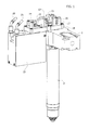
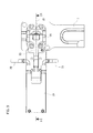
- FIG. 1 designated by 1 is a portion of hot runner of an apparatus for injection-moulding of plastic materials, through which the fluid plastic material is fed to an injector 2 that extends downwards from the hot runner 1 and co-operates, in a way in itself known, with the gate of a mould (not illustrated).
- the injector 2 is equipped with a valve pin 3 that can be displaced axially between an advanced or lowered closing position and a raised or retracted opening position to enable flow of the fluid plastic material from the hot runner 1 to the cavity of the mould.
- the axis of the valve pin 3, oriented vertically, is designated by A in Figure 3 .
- Displacement of the valve pin 3 along the axis A is governed by a rotary electric motor 4, the shaft of which, designated by 5, is set according to an axis B, which is also vertical, i.e., parallel to the axis A of the valve pin 3.
- a drive pulley 6 Fitted on the shaft 5 facing towards the bottom of the electric motor 4 is a drive pulley 6 over which an endless belt 7 is run, which actuates a driven pulley 8 fitted on the bottom end of a wormscrew 9 of a screw-and-nut transmission assembly 10 of the ball-circulation type, the internal screw of which is designated by 11 and is able to slide vertically within a guide body 22.
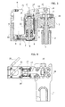
- the transmission formed by the pulleys 6, 8 with the belt 7 and by the screw-and-nut assembly 10 has an effect of multiplication of the force applied by the shaft 5 of the electric motor 4.
- the screw-and-nut assembly 10 is set immediately alongside the electric motor 4 with its own axis, designated by C in Figure 3 , oriented vertically and hence parallel to the axes A and B.
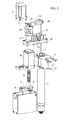
- the internal screw 11 bears at the top a support 14, to which one end of the rocker 12 is articulated in 15, the opposite end of the rocker 12 carrying a pin 16, articulated to which is the top end of the valve pin 3.
- the opposite ends of the pin 16, projecting from the rocker 12, are guided within respective vertical slits 17 of a support 18 directly fixed to the hot runner 1.
- the arms of the rocker 12 are substantially equal. These arms could, however, have different lengths, for example so as to obtain a further system of multiplication of the force transmitted by the shaft 5 of the electric motor 4 to the plug 2.
- a casing 19 that extends alongside the injector 2 and projects at the bottom lower down than the hot runner 1, within which the electric motor 4 and the screw-and-nut assembly 10, as well as the belt transmission 6, 7, 8, are housed.
- Control of the displacements of the valve pin 3 performed by the electric motor 4 through the transmission described above may be obtained in different ways, typically through an electronic circuit coming under a transducer, for example of the encoder type (not illustrated in so far as it is conventional), operatively associated to the valve pin 3 or else to any one of the components of the transmission.
- the end-of-travel positions of the valve pin 3, respectively, at the end of the step of opening and at the end of the step of closing may also be determined by arrest means of a mechanical type, for example operatively associated to the arms of the rocker 12, i.e., to the support 14 to which the pin 15 is articulated and/or to the guides 17 along which the pin 16 moves.
- Control of the electric motor 4 is conveniently obtained according to pre-defined settings, i.e., normally in a way not correlated to conditions of flow of the molten plastic material to be injected, which in this case do not need to be detected.
- the above circuit may be independent of that of the mould, and it is moreover possible to envisage two independent cooling circuits one for the motor 4 and one for the screw-and-nut assembly 10.
- the cooling circuit may conveniently be equipped with a protection system coming under a sensor for detecting the flow-rate and/or temperature of the coolant and prearranged to interrupt operation of the apparatus, and in particular supply of the hot runner 1, in the case where the flow rate and/or the temperature detected are, respectively, lower or higher than predetermined threshold values.
- a protection system coming under a sensor for detecting the flow-rate and/or temperature of the coolant and prearranged to interrupt operation of the apparatus, and in particular supply of the hot runner 1, in the case where the flow rate and/or the temperature detected are, respectively, lower or higher than predetermined threshold values.
- connection between the support 18 and the hot runner 1 on one side, as well as between the support 18 and the casing 19 on the other, is advantageously obtained in such a way as to enable selective modification of positioning thereof in different angular configurations about the axis A of the valve pin 3 and about the axis C of the screw-and-nut assembly 10, respectively.
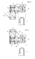
- Figures 5, 6 , and 7 exemplify some of the above alternative configurations: whereas in the case of Figures 1 to 4 the axes B and C are substantially coplanar to the axis A, so that the casing 19 projects perpendicular to the hot runner 1, in the case of Figure 5 the vertical plane containing the axes B and C is orthogonal to the plane passing through the axes C and A, so that the casing 19 is set alongside parallel to the hot runner 1.
- the electric motor 4 and the screw-and-nut assembly 10 of the ball-circulation type are in any case set laterally with respect to the injector 2 and substantially within the vertical encumbrance of the hot runner 1.
- the axis B of the electric motor 4 and the axis C of the screw-and-nut assembly 10 could also be oriented at an angle (for example, of 45° or 90°) with respect to the axis A of the valve pin 3.
- the casing 19 containing the electric motor 4, the belt transmission 6, 7, 8 and the screw-and-nut assembly 10 projects more laterally and less at the bottom than the hot runner 1, whereas the encumbrance in height remains substantially the same.
- the electric motor 4 and the screw-and-nut assembly 10 of the ball-circulation type are also in this case set alongside and parallel to one another, with the respective axes B and C oriented vertically like the axis A of the plug 3.
- the axes A and C coincide, in the sense that the screw 9 and the plug 3 are coaxial.
- the screw 9 is driven in rotation via a force multiplier formed in this case by a train of cylindrical gears 25 driven by the shaft 5 of the rotary electric motor 4.
- the internal screw 11 is coupled to the top end of the plug 3.
- the electric motor 4 and the screw-and-nut assembly 10 of the ball-circulation type are set alongside and parallel to one another and to the plug 3, with the respective axes A, B, and C oriented vertically.
- the force-multiplier system between the shaft 5 of the motor 4 and the screw 9 of the screw-and-nut assembly 10 is formed by the train of cylindrical gears 25, and actuation of the plug 3 is performed by the internal screw 11, which translates along the ball screw 9 governed in rotation by the train 25, through the further force-multiplier system formed by an oscillating lever 27.
- the oscillating lever 27 has one end 28 connected to the internal screw 11 and is articulated at the opposite end 29 to a fixed fulcrum 30.
- the top of the plug 3 is articulated to a slot 31 formed in an intermediate area of the oscillating lever 27. This arrangement enables further increase of the effect of force multiplication.
- cooling of the rotary electric motor 4 and of the screw-and-nut assembly 10 is provided via a common circuit.
- the screw-and-nut assembly 10 of the ball-circulation type is set alongside and parallel to the plug 3 with the respective axes C and A oriented vertically, whereas the motor 4 is set at the top with its own axis B oriented horizontally, i.e., orthogonal to the axes A and C.
- the force multiplier between the shaft 5 of the motor 4 and the screw 9 of the screw-and-nut assembly 10 is formed by a pair of bevel gears 26, and the force multiplier between the internal screw 11 and the plug 3 is constituted, as in the case of the embodiment of Figures 15 and 16 , by the lever 27 oscillating about the fixed fulcrum 30.
- This solution presents the advantage of enabling convenient dismantling of the motor 4 with the crown wheel and pinion 26, which are mounted independently within a recess 34 of the closing plate of the mould, from the screw 9 of the screw-and-nut assembly 10, which is mounted, together with the other components of the transmission, on the hot runner 1 through a plate 33.
- the electrical connections of the motor 4 can thus be kept within the closing plate of the mould, which reduces the risk of damage due to the heat of the hot runner, at the same time guaranteeing easier assembly and more convenient maintenance.
Landscapes
- Engineering & Computer Science (AREA)
- Manufacturing & Machinery (AREA)
- Mechanical Engineering (AREA)
- Moulds For Moulding Plastics Or The Like (AREA)
- Injection Moulding Of Plastics Or The Like (AREA)
- Transmission Devices (AREA)
Abstract
Description
- The present invention relates to apparatuses for injection-moulding of plastic materials comprising a hot runner, at least one injector that includes a nozzle within which a valve pin is axially movable, and actuator means for governing axial displacement of the valve pin between a closing position and an opening position to enable flow of fluid plastic material under pressure from the hot runner into a mould cavity.
- More in particular, the invention regards a moulding apparatus of the above sort, in which the actuator means that govern axial displacement of the valve pin consist of an electric motor.
- The use of an electric motor for governing the valve pin of the injector presents, as compared to conventional systems that use for this function (hydraulic or pneumatic) fluid actuators, the advantage of enabling a continuous and hence more accurate and precise control of the position of the open/close element and, consequently, of the flow of the fluid plastic material from the hot runner into the cavity of the mould.
- Known from the U.S. patent No.
US-7,214,048 is an injection-moulding apparatus of the type defined above in which directly associated to each injector is a linear electric motor set coaxially to the valve pin, above the hot runner. - The Japanese patent application No.
JP-A-6114887 US-7,121,820 describe solutions in which the electric motor, also in this case set above the hot runner coaxial to the injector, is a rotary motor and actuates the valve pin through a screw-and-nut assembly transmission. - All these solutions entail the drawback of presenting a considerable encumbrance in the vertical direction that results in an increase in height of the moulding apparatus as a whole.
- Likewise known from the U.S. patent No.
US-6,294,122 is an injection-moulding apparatus of the aforesaid type, in which the rotary electric motor that actuates the valve pin of each injector, also in this case through a screw-and-nut transmission, is also set coaxial to the injector above the hot runner. In one solution, represented inFigures 6-8 , the electric motor is set with its axis oriented perpendicular to the axis of the injector and governs, via a pair of bevel gears, the screw-and-nut transmission that actuates the valve pin. Since the screw-and-nut transmission is also set coaxially above the valve pin, also in this case the arrangement of the electric motor and of the corresponding transmission leads to a considerable encumbrance upwards above the hot runner. - The object of the present invention is to overcome the drawbacks referred to above, and more in particular to provide an apparatus for injection-moulding of plastic materials of the type defined above, the vertical encumbrance of which may be contained substantially within the height of the hot runner, or in any case will be appreciably reduced.
- With a view to achieving the above object, the subject of the invention is an apparatus for injection-moulding of plastic materials as defined in the preamble of
Claim 1, the primary characteristic of which lies in the fact that at least two from among said valve pin, said rotary electric motor, and said screw-and-nut assembly are set parallel alongside one another. - Thanks to this arrangement, since the injector typically projects underneath the hot runner, also the electric motor and the screw-and-nut assembly can be substantially kept within the vertical encumbrance thereof. But also in the case where the motor and possible components of the transmission are, instead, set at the top, the overall dimensions are in any case limited.
- The valve pin defines a first axis, the shaft of the electric motor defines a second axis, and the screw-and-nut assembly defines a third axis. The invention envisages multiple different embodiments in which the second and third axes are parallel to one another and to the first axis, and in this case the first and third axes may even coincide, or else embodiments in which the second and third axes are parallel to one another and orthogonal to the first axis, or yet again embodiments in which the first and third axes are parallel to one another and orthogonal to the second axis.
- According to a further characteristic of the invention, the transmission that converts the rotation of the shaft of the rotary electric motor into a translation of the valve pin conveniently comprises force-multiplier means set between the shaft of the electric motor and the screw of the screw-and-nut assembly, and may also include further force-multiplier means set between the screw-and-nut assembly and the valve pin.
- The electric motor and the screw-and-nut assembly may be conveniently housed within a common supporting casing that may be fixed to the hot runner in different angular positions that can be selected, according to the need, about the axis of the valve pin.
- Control of the electric motor may be obtained in a conventional way with the aid of a linear-position or angular-position transducer operatively associated to the valve pin, or else to the screw-and-nut assembly, or to any other component of the transmission, operatively connected to an electronic circuit for closed-loop control of the electric motor.
- According to another aspect of the invention, a circuit is provided for forced cooling of the electric motor as well as, jointly or separately, of the screw-and-nut assembly, to which there may be associated a flow-rate sensor and/or a temperature sensor designed to interrupt automatically electrical supply of the hot runner in the case of emergency. This prevents the risk of overheating of the mechanical and electro-mechanical members (transmission, electric motor), which have to operate at temperatures that are not too far above ambient temperature and in any case much lower than those of the hot runner.
- The invention will now be described in detail with reference to the annexed drawings, which are provided purely by way of non-limiting example and in which:
-
Figure 1 is a schematic perspective view of a part of an apparatus for injection-moulding of plastic materials according to a first embodiment of the invention; -
Figure 2 is an exploded view ofFigure 1 ; -
Figure 3 is a partial view in vertical section ofFigure 1 ; -
Figure 4 is a top plan view ofFigure 1 ; -
Figures 5, 6 and7 are views similar to that ofFigure 4 of respective variants of the apparatus according to the invention; -
Figure 8 is a schematic perspective view, similar to that ofFigure 1 , of a further variant of the invention; -
Figure 9 is a top plan view ofFigure 8 ; -
Figure 10 is a cross-sectional view according to the line X-X ofFigure 9 ; -
Figure 11 is a schematic perspective view of a detail ofFigures 3 and10 ; -
Figure 12 is a schematic side elevation of another variant of the invention; -
Figure 13 is a vertical section ofFigure 12 ; -
Figure 14 is a dorsal view ofFigure 12 ; -
Figure 15 is a view in vertical section of a further variant of the invention; -
Figure 16 is a view in partial horizontal section ofFigure 15 ; and -
Figure 17 is a view in vertical section of another variant of the invention. - With initial reference to
Figures 1 to 4 , designated by 1 is a portion of hot runner of an apparatus for injection-moulding of plastic materials, through which the fluid plastic material is fed to aninjector 2 that extends downwards from thehot runner 1 and co-operates, in a way in itself known, with the gate of a mould (not illustrated). - Once again in a way in itself known, and as may be seen in
Figures 2 and3 , theinjector 2 is equipped with avalve pin 3 that can be displaced axially between an advanced or lowered closing position and a raised or retracted opening position to enable flow of the fluid plastic material from thehot runner 1 to the cavity of the mould. The axis of thevalve pin 3, oriented vertically, is designated by A inFigure 3 . - Displacement of the
valve pin 3 along the axis A is governed by a rotaryelectric motor 4, the shaft of which, designated by 5, is set according to an axis B, which is also vertical, i.e., parallel to the axis A of thevalve pin 3. - Fitted on the
shaft 5 facing towards the bottom of theelectric motor 4 is adrive pulley 6 over which anendless belt 7 is run, which actuates a drivenpulley 8 fitted on the bottom end of awormscrew 9 of a screw-and-nut transmission assembly 10 of the ball-circulation type, the internal screw of which is designated by 11 and is able to slide vertically within aguide body 22. - The transmission formed by the
pulleys belt 7 and by the screw-and-nut assembly 10 has an effect of multiplication of the force applied by theshaft 5 of theelectric motor 4. - The screw-and-
nut assembly 10 is set immediately alongside theelectric motor 4 with its own axis, designated by C inFigure 3 , oriented vertically and hence parallel to the axes A and B. - The
internal screw 11, moved in translation as a result of rotation of thescrew 9 governed by themotor 4 via thepulleys belt 7, in turn actuates - as has been said with a multiplying effect - arocker 12 oscillating about a centralhorizontal axis 13 for governing translation of thevalve pin 3. In greater detail, and as is more clearly represented inFigures 2 and3 , theinternal screw 11 bears at the top asupport 14, to which one end of therocker 12 is articulated in 15, the opposite end of therocker 12 carrying apin 16, articulated to which is the top end of thevalve pin 3. The opposite ends of thepin 16, projecting from therocker 12, are guided within respectivevertical slits 17 of asupport 18 directly fixed to thehot runner 1. - In the case of the example represented, the arms of the
rocker 12 are substantially equal. These arms could, however, have different lengths, for example so as to obtain a further system of multiplication of the force transmitted by theshaft 5 of theelectric motor 4 to theplug 2. - Moreover fixed at the bottom, alongside the
hot runner 1, to thesupport 18 is acasing 19 that extends alongside theinjector 2 and projects at the bottom lower down than thehot runner 1, within which theelectric motor 4 and the screw-and-nut assembly 10, as well as thebelt transmission - With the arrangement described, where, as has been said, the
electric motor 4 and the screw-and-nut assembly 10 are both set laterally alongside theinjector 2 with the respective axes B, C parallel to the axis A, the vertical encumbrance of thehot runner 1 and of the moulding apparatus as a whole is appreciably contained. - Control of the displacements of the
valve pin 3 performed by theelectric motor 4 through the transmission described above (thepulleys endless belt 7, the screw-and-nut assembly 10, and the rocker lever 12) may be obtained in different ways, typically through an electronic circuit coming under a transducer, for example of the encoder type (not illustrated in so far as it is conventional), operatively associated to thevalve pin 3 or else to any one of the components of the transmission. As an alternative, or in addition, the end-of-travel positions of thevalve pin 3, respectively, at the end of the step of opening and at the end of the step of closing, may also be determined by arrest means of a mechanical type, for example operatively associated to the arms of therocker 12, i.e., to thesupport 14 to which thepin 15 is articulated and/or to theguides 17 along which thepin 16 moves. - Control of the
electric motor 4 is conveniently obtained according to pre-defined settings, i.e., normally in a way not correlated to conditions of flow of the molten plastic material to be injected, which in this case do not need to be detected. - For cooling of the
electric motor 4, as well as of the screw-and-nut assembly 10, there is provided a circuit for circulation of a coolant through aninlet connector 20 and anoutlet connector 21 carried by thecasing 19 and corresponding channels, designated as a whole by 22 inFigure 11 . The above circuit may be independent of that of the mould, and it is moreover possible to envisage two independent cooling circuits one for themotor 4 and one for the screw-and-nut assembly 10. - The cooling circuit may conveniently be equipped with a protection system coming under a sensor for detecting the flow-rate and/or temperature of the coolant and prearranged to interrupt operation of the apparatus, and in particular supply of the
hot runner 1, in the case where the flow rate and/or the temperature detected are, respectively, lower or higher than predetermined threshold values. In this way, there is prevented the risk of overheating of the mechanical and electro-mechanical members (transmission, electric motor), which have to work at temperatures that are not too far above the ambient temperature and in any case much lower than those of the hot runner. - The connection between the
support 18 and thehot runner 1 on one side, as well as between thesupport 18 and thecasing 19 on the other, is advantageously obtained in such a way as to enable selective modification of positioning thereof in different angular configurations about the axis A of thevalve pin 3 and about the axis C of the screw-and-nut assembly 10, respectively. -
Figures 5, 6 , and7 exemplify some of the above alternative configurations: whereas in the case ofFigures 1 to 4 the axes B and C are substantially coplanar to the axis A, so that thecasing 19 projects perpendicular to thehot runner 1, in the case ofFigure 5 the vertical plane containing the axes B and C is orthogonal to the plane passing through the axes C and A, so that thecasing 19 is set alongside parallel to thehot runner 1. In the case ofFigure 6 , the arrangement is similar, except for the fact that thecasing 19 is rotated through 180° with respect to the configuration represented inFigure 5 , whereas in the case ofFigure 7 thesupport 18, instead of being perpendicular to thehot runner 1, is set on its prolongation, with the axes A, B and C, which also in this case are coplanar. - Of course, there may be devised different configurations also with different angles, provided that the
electric motor 4 and the screw-and-nut assembly 10 of the ball-circulation type are in any case set laterally with respect to theinjector 2 and substantially within the vertical encumbrance of thehot runner 1. Thus, the axis B of theelectric motor 4 and the axis C of the screw-and-nut assembly 10 could also be oriented at an angle (for example, of 45° or 90°) with respect to the axis A of thevalve pin 3. - The variant represented in
Figures 8-10 , in which parts that are identical or similar to the ones already described previously are designated by the same reference numbers, illustrates a solution in which theelectric motor 4 and the screw-and-nut assembly 10 of the ball-circulation type are set alongside and parallel to one another with the respective axes B and C oriented horizontally, i.e., perpendicular to the axis A of theplug 3. In this case, therocker 12 is replaced by a substantially L-shaped oscillatinglever 23, which performs the function of further multiplier of the force applied by theshaft 5 of theelectric motor 4 on theplug 2. - As compared to the solutions described previously, in this case the
casing 19 containing theelectric motor 4, thebelt transmission nut assembly 10 projects more laterally and less at the bottom than thehot runner 1, whereas the encumbrance in height remains substantially the same. - In the variant represented in
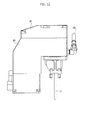
Figures 12 to 14 , where also here parts that are identical or similar to those already described previously are designated by the same reference numbers, theelectric motor 4 and the screw-and-nut assembly 10 of the ball-circulation type are also in this case set alongside and parallel to one another, with the respective axes B and C oriented vertically like the axis A of theplug 3. However, in this case the axes A and C coincide, in the sense that thescrew 9 and theplug 3 are coaxial. Thescrew 9 is driven in rotation via a force multiplier formed in this case by a train ofcylindrical gears 25 driven by theshaft 5 of the rotaryelectric motor 4. Theinternal screw 11 is coupled to the top end of theplug 3. - Also in the case of the variant illustrated in
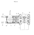
Figures 15 and16 , currently considered as the preferred embodiment, theelectric motor 4 and the screw-and-nut assembly 10 of the ball-circulation type are set alongside and parallel to one another and to theplug 3, with the respective axes A, B, and C oriented vertically. - Unlike the embodiment of
Figures 1-4 , the force-multiplier system between theshaft 5 of themotor 4 and thescrew 9 of the screw-and-nut assembly 10 is formed by the train ofcylindrical gears 25, and actuation of theplug 3 is performed by theinternal screw 11, which translates along theball screw 9 governed in rotation by thetrain 25, through the further force-multiplier system formed by an oscillatinglever 27. - The oscillating
lever 27 has oneend 28 connected to theinternal screw 11 and is articulated at theopposite end 29 to a fixedfulcrum 30. The top of theplug 3 is articulated to aslot 31 formed in an intermediate area of theoscillating lever 27. This arrangement enables further increase of the effect of force multiplication. - Also in this case, cooling of the rotary
electric motor 4 and of the screw-and-nut assembly 10 is provided via a common circuit. - Finally, in the embodiment represented in
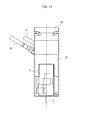
Figure 17 , the screw-and-nut assembly 10 of the ball-circulation type is set alongside and parallel to theplug 3 with the respective axes C and A oriented vertically, whereas themotor 4 is set at the top with its own axis B oriented horizontally, i.e., orthogonal to the axes A and C. - In this case, the force multiplier between the
shaft 5 of themotor 4 and thescrew 9 of the screw-and-nut assembly 10 is formed by a pair ofbevel gears 26, and the force multiplier between theinternal screw 11 and theplug 3 is constituted, as in the case of the embodiment ofFigures 15 and16 , by thelever 27 oscillating about the fixedfulcrum 30. - This solution presents the advantage of enabling convenient dismantling of the
motor 4 with the crown wheel andpinion 26, which are mounted independently within arecess 34 of the closing plate of the mould, from thescrew 9 of the screw-and-nut assembly 10, which is mounted, together with the other components of the transmission, on thehot runner 1 through aplate 33. The electrical connections of themotor 4 can thus be kept within the closing plate of the mould, which reduces the risk of damage due to the heat of the hot runner, at the same time guaranteeing easier assembly and more convenient maintenance. - Of course, the details of construction and the embodiments may vary widely with respect to what has been described and illustrated herein, without thereby departing from the scope of the present invention as defined in the ensuing claims.
Claims (23)
- An apparatus for injection-moulding of plastic materials comprising a hot runner (1), at least one injector (2) including a nozzle, within which a valve pin (3) is axially movable, and actuator means for governing axial displacement of the valve pin (3) between a closing position and an opening position to enable flow of fluid plastic material under pressure from the hot runner (1) into a mould cavity, wherein the actuator means include a rotary electric motor (4) and a transmission including a screw-and-nut assembly (10) for converting the rotation of the shaft (5) of the rotary electric motor (4) into a translation of the valve pin (3), said apparatus being characterized in that at least two from among said valve pin (3), said rotary electric motor (4) and said screw-and-nut assembly (10) are set parallel alongside one another.
- The apparatus according to Claim 1, wherein the valve pin (3) defines a first axis (A), the shaft of the electric motor (4) defines a second axis (B), and the screw-and-nut assembly (10) defines a third axis (C), characterized in that the second and third axes (B, C) are parallel to one another and to the first axis (A).
- The apparatus according to Claim 1, wherein the valve pin (3) defines a first axis (A), the shaft of the electric motor (5) defines a second axis (B), and the screw-and-nut assembly (10) defines a third axis (C), characterized in that the second and third axes (B, C) are parallel to one another and orthogonal to the first axis (A).
- The apparatus according to Claim 1, wherein the valve pin (3) defines a first axis (A), the shaft of the electric motor (5) defines a second axis (B), and the screw-and-nut assembly (10) defines a third axis (C), characterized in that the first and third axes (A, C) are parallel to one another and orthogonal to the second axis (B).
- The apparatus according to Claim 2, characterized in that the first and third axes (A, C) are coincident.
- The apparatus according to any one of the preceding claims, characterized in that said transmission comprises force-multiplier means (6, 7, 8; 25; 26) set between the shaft (5) of the electric motor (4) and the screw (9) of the screw-and-nut assembly (10).
- The apparatus according to Claim 6, characterized in that said force-multiplier means include an endless belt (7) running over a pair of pulleys, a drive pulley (6) and a driven pulley (8) coupled in rotation, respectively, to the shaft (5) of the electric motor (4) and to the screw (9) of the screw-and-nut assembly (10).
- The apparatus according to Claim 6, characterized in that said force-multiplier means include a train of cylindrical gears (25) that couple in rotation the shaft (5) of the electric motor (4) and the screw (9) of the screw-and-nut assembly (10).
- The apparatus according to Claim 6, characterized in that said force-multiplier means include a pair of bevel gears (26) that couple in rotation the shaft (5) of the electric motor (4) and the screw (9) of the screw-and-nut assembly (10).
- The apparatus according to Claim 6, characterized in that it includes further force-multiplier means (12; 23; 27) set between the screw-and-nut assembly (10) and the valve pin (3).
- The apparatus Claim 10, characterized in that said further force-multiplier means include a rocker lever (12; 23) driven by the screw (11) of the screw-and-nut assembly (10) for governing the valve pin (3).
- The apparatus according to Claim 11, characterized in that said rocker lever (12; 23) is articulated at one end (15) to said screw (11) and at the opposite end (16) to the valve pin (3) through linear guide means (14, 17).
- The apparatus according to Claim 12, characterized in that said linear guide means (14, 17) define end-of-travel arrests for the valve pin (3).
- The apparatus Claim 10, characterized in that said further force-multiplier means include an oscillating lever (27) having one end (28) connected to said screw (11) and articulated at the opposite end (29) to a fixed axis (30), an intermediate area (31) of said oscillating lever (27) being articulated to the valve pin (3).
- The apparatus according to one or more of the preceding claims, characterized in that it moreover includes transducer means for detection of the travel of said valve pin (3) and control of said rotary electric motor (4).
- The apparatus according to one or more of the preceding claims, characterized in that said rotary electric motor (4) and said transmission (10; 6, 7, 8; 25, 12; 23; 27) are carried by a support (18) directly fixed to the hot runner (1).
- The apparatus according to Claim 16, characterized in that said support (18) is configured to be fixed to the hot runner (1) in different selectable angular positions about the axis (A) of the valve pin (3).
- The apparatus according to Claim 16, characterized in that said rotary electric motor (4) and said screw-and-nut assembly (10) are housed within a common casing (19) that can be fixed to said support (18) in different selectable angular positions about the axis (C) of the screw-and-nut assembly (10).
- The apparatus according to Claim 18, characterized in that said casing (19) includes channels (20, 21, 22) for circulation of a coolant for the rotary electric motor (4) and for the screw-and-nut assembly (10).
- The apparatus according to Claim 19, characterized in that said channels are in common for the rotary electric motor (4) and for the screw-and-nut assembly (10).
- The apparatus according to Claim 19, characterized in that said channels are separate for the rotary electric motor (4) and for the screw-and-nut assembly (10).
- The apparatus according to Claim 19, characterized in that it moreover includes means for detecting the flow rate and/or the temperature of said coolant, which are operatively connected to a system for protection of the apparatus.
- The apparatus according to one or more of Claims 1 to 15, characterized in that said rotary electric motor (4) and said screw-and-nut assembly (10) are supported independently from each other.
Applications Claiming Priority (1)
| Application Number | Priority Date | Filing Date | Title |
|---|---|---|---|
| IT000578A ITTO20120578A1 (en) | 2012-06-28 | 2012-06-28 | PLASTIC INJECTION MOLDING EQUIPMENT |
Publications (2)
| Publication Number | Publication Date |
|---|---|
| EP2679374A1 true EP2679374A1 (en) | 2014-01-01 |
| EP2679374B1 EP2679374B1 (en) | 2016-09-07 |
Family
ID=46727459
Family Applications (1)
| Application Number | Title | Priority Date | Filing Date |
|---|---|---|---|
| EP13171982.5A Active EP2679374B1 (en) | 2012-06-28 | 2013-06-14 | Apparatus for injection-moulding of plastic materials |
Country Status (6)
| Country | Link |
|---|---|
| US (1) | US9102085B2 (en) |
| EP (1) | EP2679374B1 (en) |
| JP (1) | JP6192386B2 (en) |
| CN (1) | CN103538209B (en) |
| BR (1) | BR102013016705B1 (en) |
| IT (1) | ITTO20120578A1 (en) |
Cited By (30)
| Publication number | Priority date | Publication date | Assignee | Title |
|---|---|---|---|---|
| DE202014103153U1 (en) | 2013-12-24 | 2014-10-17 | Inglass S.P.A. | Device for injection molding plastic materials |
| DE202014103152U1 (en) | 2013-12-24 | 2014-10-20 | Inglass S.P.A. | Device for injection molding plastic materials |
| EP2918389A1 (en) | 2014-03-10 | 2015-09-16 | Inglass S.p.A. | Fixing plate of the mold of an injection molding apparatus of plastic material |
| DE202015106658U1 (en) | 2014-12-10 | 2016-01-18 | Inglass S.P.A. | Injector for plastic injection molding equipment |
| DE102015114845A1 (en) | 2014-09-08 | 2016-03-10 | Inglass S.P.A. | Method and apparatus for injection molding plastic materials |
| EP3009251A1 (en) | 2014-10-15 | 2016-04-20 | Inglass S.p.A. | Apparatus for injection molding of plastic material |
| DE102015121498A1 (en) | 2014-12-11 | 2016-06-16 | Inglass S.P.A. | Method and device for injection molding of plastics |
| DE102015121454A1 (en) | 2014-12-10 | 2016-06-16 | Inglass S.P.A. | Shaping apparatus and method for producing shaped articles by sequential injection molding |
| DE102016101523A1 (en) | 2015-01-28 | 2016-07-28 | Inglass S.P.A. | System and method for injection molding of plastics |
| DE102016104503A1 (en) | 2015-03-12 | 2016-09-15 | Inglass S.P.A. | Method and device for injection molding of plastics |
| DE102016108623A1 (en) | 2015-05-11 | 2016-11-17 | Inglass S.P.A. | Method for influencing a device for injection molding of plastics |
| ITUB20156839A1 (en) * | 2015-12-10 | 2017-06-10 | Inglass Spa | PLASTIC INJECTION MOLDING EQUIPMENT |
| WO2018020177A1 (en) | 2016-07-28 | 2018-02-01 | Runipsys Europe | System for controlling a shutter of a plastics injection system |
| WO2018129015A1 (en) * | 2017-01-05 | 2018-07-12 | Synventive Molding Solutions, Inc. | Remotely mounted electric motor driving a valve pin in an injection molding apparatus |
| DE102018113404A1 (en) | 2017-06-08 | 2018-12-13 | Inglass S.P.A. | Device for injection molding plastic materials |
| WO2019100085A1 (en) * | 2017-11-14 | 2019-05-23 | Synventive Molding Solutions, Inc. | Actuator with eccentric pin drive |
| FR3076482A1 (en) | 2018-12-07 | 2019-07-12 | Runipsys Europe | SYSTEM FOR CONTROLLING A SHUTTER OF A PLASTIC MATERIAL INJECTION SYSTEM |
| EP3342575B1 (en) | 2013-07-08 | 2019-09-25 | Synventive Molding Solutions, Inc. | Non-coaxially mounted electric actuator and transmission |
| WO2019207482A1 (en) * | 2018-04-23 | 2019-10-31 | Yudo Eu, S.A. | Lateral support for mounting a cylinder in an injection-moulding system |
| FR3088847A1 (en) | 2018-11-28 | 2020-05-29 | Runipsys Europe | CONTROL SYSTEM FOR A SHUTTER OF A PLASTIC INJECTION SYSTEM |
| WO2020176479A1 (en) * | 2019-02-25 | 2020-09-03 | Synventive Molding Solutions, Inc. | Cooled electric actuator controlled injection |
| EP3718734A1 (en) | 2018-05-31 | 2020-10-07 | Inglass S.p.A. | Process and apparatus for injection molding of plastic materials |
| US10899056B2 (en) | 2011-11-23 | 2021-01-26 | Synventive Molding Solutions, Inc. | Non-coaxially mounted electric actuator and transmission |
| EP3769929A1 (en) * | 2019-07-21 | 2021-01-27 | Incoe International, Inc. | Electric actuator for driving a hotrunner valve pin |
| EP3804949A1 (en) | 2019-10-11 | 2021-04-14 | INCOE Corporation USA | Hot-runner assembly with axially mounted electric actuator |
| US11186020B2 (en) | 2015-03-20 | 2021-11-30 | Synventive Molding Solutions, Inc. | Actuator with eccentric pin drive |
| US11878453B2 (en) | 2019-07-21 | 2024-01-23 | Incoe Corporation | Leak protection bushing for hotrunner manifold assembly |
| US12134219B2 (en) | 2019-02-25 | 2024-11-05 | Synventive Molding Solutions, Inc. | Injection molding apparatus with insulated integrated actuator electronic drive |
| US12168316B2 (en) | 2019-02-25 | 2024-12-17 | Synventive Molding Solutions, Inc. | Injection molding apparatus with insulated integrated actuator electronic drive |
| US12172354B2 (en) | 2019-10-21 | 2024-12-24 | Synventive Molding Solutions, Inc. | Electric actuator drive for injection molding flow control |
Families Citing this family (13)
| Publication number | Priority date | Publication date | Assignee | Title |
|---|---|---|---|---|
| CN103249538B (en) | 2010-11-23 | 2015-08-26 | 圣万提注塑工业有限公司 | Injection mo(u)lding flow control apparatus and method |
| CN104249439A (en) * | 2014-09-12 | 2014-12-31 | 苏州好特斯模具有限公司 | Single-point lever needle valve type hot nozzle for high temperature glass fiber injection |
| CN104249435A (en) * | 2014-09-12 | 2014-12-31 | 苏州好特斯模具有限公司 | Lever support for single-point lever needle valve type hot nozzle |
| DE102016003970A1 (en) * | 2015-04-02 | 2016-10-06 | Otto Männer Innovation GmbH | Hot runner device for lateral casting with continuous valve needle movement |
| JP6591774B2 (en) * | 2015-04-09 | 2019-10-16 | エスバンス 株式会社 | Drive device for valve pin in injection mold |
| CN104827633A (en) * | 2015-05-05 | 2015-08-12 | 浙江恒道科技有限公司 | Side-sway cylinder |
| IT201700105306A1 (en) | 2017-09-20 | 2019-03-20 | Inglass Spa | PROCEDURE AND EQUIPMENT FOR THE PRODUCTION OF ITEMS INJECTION MOLDED PLASTIC CABLES |
| DE102017125767A1 (en) * | 2017-11-03 | 2019-05-23 | Günther Heisskanaltechnik Gmbh | Lifting plate drive for needle valve closing systems for servomotors |
| ES2718945A1 (en) * | 2018-01-05 | 2019-07-05 | Comercial De Utiles Y Moldes Sa | Hydraulic cylinder (Machine-translation by Google Translate, not legally binding) |
| IT201800002639A1 (en) | 2018-02-13 | 2019-08-13 | Inglass Spa | PROCEDURE AND EQUIPMENT FOR INJECTION MOLDING OF PLASTIC MATERIALS |
| IT201800004581A1 (en) * | 2018-04-16 | 2019-10-16 | PLASTIC INJECTION MOLDING EQUIPMENT | |
| JP6823724B1 (en) * | 2019-06-26 | 2021-02-03 | シミズ工業株式会社 | Injection molding equipment |
| CN116685451A (en) * | 2020-12-08 | 2023-09-01 | 圣万提注塑工业有限公司 | Injection molding unit with cooling integrated actuator electric drive |
Citations (10)
| Publication number | Priority date | Publication date | Assignee | Title |
|---|---|---|---|---|
| US2773284A (en) * | 1953-03-13 | 1956-12-11 | Columbus Plastic Products Inc | Die construction for pressure injection molding machines |
| US3488810A (en) * | 1967-03-17 | 1970-01-13 | Jobst U Gellert | Valve-gated mold construction |
| JPH06114887A (en) * | 1992-10-07 | 1994-04-26 | Mitsubishi Materials Corp | Injection mold |
| US5948450A (en) * | 1996-09-27 | 1999-09-07 | Dynisco Hotrunners, Inc. | Valve actuated injection molding apparatus |
| DE19857735A1 (en) * | 1998-12-15 | 2000-06-29 | Hansjuergen Moeser | Actuating and regulating device for a hot or cold runner of a plastic molding tool |
| DE19956215A1 (en) * | 1999-11-23 | 2001-06-21 | Otto Maenner Heiskanalsysteme | Needle valve for plastics injection molding tool has needle operated by positioning motor |
| US20080014296A1 (en) * | 2003-11-11 | 2008-01-17 | Plastic Engineering & Technical Services, Inc. | Valve gate assembly |
| DE102008029216A1 (en) * | 2007-06-22 | 2008-12-24 | Mold-Masters (2007) Limited, Georgetown | Injection-molding nozzle, has motor, power wheel connected with motor, belt or chain connected with power wheel, and drive gear, which is connected with belt or chain |
| EP2008790A2 (en) * | 2007-06-27 | 2008-12-31 | AWM Mold Tech AG | Needle lock nozzle assembly |
| WO2010126330A2 (en) * | 2009-04-30 | 2010-11-04 | Kim Hyuk Joong | Hot runner valve apparatus for an injection molder |
Family Cites Families (15)
| Publication number | Priority date | Publication date | Assignee | Title |
|---|---|---|---|---|
| US3371384A (en) * | 1965-05-06 | 1968-03-05 | Lenslite Co Inc | Injection valve pressure regulator |
| US3530539A (en) * | 1968-02-02 | 1970-09-29 | Gellert Jobst U | Gate valve for injection molding machines |
| CA1261579A (en) * | 1987-03-19 | 1989-09-26 | Mold-Masters Limited | Replaceable rocker arm assembly for injection molding system |
| CA1261571A (en) * | 1987-12-17 | 1989-09-26 | Jobst U. Gellert | Injection molding single nozzle valve gating |
| JP2908971B2 (en) * | 1993-11-25 | 1999-06-23 | 松下電工株式会社 | Mold opening / closing device for hot runner gate |
| CA2115613C (en) * | 1994-02-14 | 2002-02-12 | Jobst Ulrich Gellert | Injection molding valve member sealing bushing with thin collar portion |
| US7234929B2 (en) * | 1999-09-21 | 2007-06-26 | Synventive Molding Solutions, Inc. | Injection molding flow control apparatus and method |
| CA2261367C (en) * | 1999-02-08 | 2008-04-22 | Mold-Masters Limited | Injection molding valve member actuating mechanism |
| CN100513131C (en) * | 2003-11-11 | 2009-07-15 | 塑胶工程与技术服务有限公司 | Valve gate assembly |
| WO2006080807A1 (en) * | 2005-01-27 | 2006-08-03 | Hyuk Joong Kim | Injection molding machine for multicavity |
| CA2592237A1 (en) * | 2006-06-19 | 2007-12-19 | Murray Feick | Valve pin actuating device for a hot runner apparatus |
| US8091202B2 (en) * | 2009-05-06 | 2012-01-10 | Synventive Molding Solutions, Inc. | Method and apparatus for coupling and uncoupling an injection valve pin |
| DE102010034451B4 (en) * | 2009-08-25 | 2013-07-04 | Engel Austria Gmbh | Ejector device with additional ejector force |
| CN201784131U (en) * | 2010-07-27 | 2011-04-06 | 上海索菲玛汽车滤清器有限公司 | Injection mold for fuel oil filtering and filling pipe |
| WO2013074554A1 (en) * | 2011-11-15 | 2013-05-23 | Husky Injection Modling Systems Ltd. | Reducing crown flash in injection-molding processes |
-
2012
- 2012-06-28 IT IT000578A patent/ITTO20120578A1/en unknown
-
2013
- 2013-06-14 EP EP13171982.5A patent/EP2679374B1/en active Active
- 2013-06-27 BR BR102013016705-3A patent/BR102013016705B1/en active IP Right Grant
- 2013-06-27 US US13/928,944 patent/US9102085B2/en active Active
- 2013-06-27 JP JP2013135134A patent/JP6192386B2/en not_active Expired - Fee Related
- 2013-06-28 CN CN201310394451.3A patent/CN103538209B/en active Active
Patent Citations (10)
| Publication number | Priority date | Publication date | Assignee | Title |
|---|---|---|---|---|
| US2773284A (en) * | 1953-03-13 | 1956-12-11 | Columbus Plastic Products Inc | Die construction for pressure injection molding machines |
| US3488810A (en) * | 1967-03-17 | 1970-01-13 | Jobst U Gellert | Valve-gated mold construction |
| JPH06114887A (en) * | 1992-10-07 | 1994-04-26 | Mitsubishi Materials Corp | Injection mold |
| US5948450A (en) * | 1996-09-27 | 1999-09-07 | Dynisco Hotrunners, Inc. | Valve actuated injection molding apparatus |
| DE19857735A1 (en) * | 1998-12-15 | 2000-06-29 | Hansjuergen Moeser | Actuating and regulating device for a hot or cold runner of a plastic molding tool |
| DE19956215A1 (en) * | 1999-11-23 | 2001-06-21 | Otto Maenner Heiskanalsysteme | Needle valve for plastics injection molding tool has needle operated by positioning motor |
| US20080014296A1 (en) * | 2003-11-11 | 2008-01-17 | Plastic Engineering & Technical Services, Inc. | Valve gate assembly |
| DE102008029216A1 (en) * | 2007-06-22 | 2008-12-24 | Mold-Masters (2007) Limited, Georgetown | Injection-molding nozzle, has motor, power wheel connected with motor, belt or chain connected with power wheel, and drive gear, which is connected with belt or chain |
| EP2008790A2 (en) * | 2007-06-27 | 2008-12-31 | AWM Mold Tech AG | Needle lock nozzle assembly |
| WO2010126330A2 (en) * | 2009-04-30 | 2010-11-04 | Kim Hyuk Joong | Hot runner valve apparatus for an injection molder |
Cited By (50)
| Publication number | Priority date | Publication date | Assignee | Title |
|---|---|---|---|---|
| US10899056B2 (en) | 2011-11-23 | 2021-01-26 | Synventive Molding Solutions, Inc. | Non-coaxially mounted electric actuator and transmission |
| EP3488989B1 (en) * | 2013-07-08 | 2020-12-09 | Synventive Molding Solutions, Inc. | Non-coaxially mounted electric actuator and transmission |
| EP3342575B1 (en) | 2013-07-08 | 2019-09-25 | Synventive Molding Solutions, Inc. | Non-coaxially mounted electric actuator and transmission |
| DE202014103153U1 (en) | 2013-12-24 | 2014-10-17 | Inglass S.P.A. | Device for injection molding plastic materials |
| DE202014103152U1 (en) | 2013-12-24 | 2014-10-20 | Inglass S.P.A. | Device for injection molding plastic materials |
| EP2918389A1 (en) | 2014-03-10 | 2015-09-16 | Inglass S.p.A. | Fixing plate of the mold of an injection molding apparatus of plastic material |
| KR20150105929A (en) * | 2014-03-10 | 2015-09-18 | 인글라스 에스피에이 | Fixing plate of the mold of an injection molding apparatus of plastic material |
| US9346206B2 (en) | 2014-03-10 | 2016-05-24 | Inglass S.P.A. | Fixing plate of a mold of an injection molding apparatus for plastic material |
| EP3326776A1 (en) * | 2014-03-10 | 2018-05-30 | Inglass S.p.A. | Fixing plate of the mold of an injection molding apparatus of plastic material |
| KR20180108549A (en) * | 2014-09-08 | 2018-10-04 | 인글라스 에스피에이 | Method and apparatus for injection molding of plastic materials |
| DE102015114845B4 (en) | 2014-09-08 | 2020-07-02 | Inglass S.P.A. | Method and device for injection molding plastic materials |
| DE102015114845A1 (en) | 2014-09-08 | 2016-03-10 | Inglass S.P.A. | Method and apparatus for injection molding plastic materials |
| EP3009251A1 (en) | 2014-10-15 | 2016-04-20 | Inglass S.p.A. | Apparatus for injection molding of plastic material |
| EP3785880A1 (en) | 2014-10-15 | 2021-03-03 | Inglass S.p.A. | Apparatus for injection molding of plastic material |
| DE102015121454B4 (en) | 2014-12-10 | 2019-06-13 | Inglass S.P.A. | Shaping apparatus and molding method for producing molded articles by sequential injection molding |
| DE102015121454A1 (en) | 2014-12-10 | 2016-06-16 | Inglass S.P.A. | Shaping apparatus and method for producing shaped articles by sequential injection molding |
| DE202015106658U1 (en) | 2014-12-10 | 2016-01-18 | Inglass S.P.A. | Injector for plastic injection molding equipment |
| DE102015121498A1 (en) | 2014-12-11 | 2016-06-16 | Inglass S.P.A. | Method and device for injection molding of plastics |
| DE102015121498B4 (en) | 2014-12-11 | 2019-10-17 | Inglass S.P.A. | Method and device for injection molding of plastics |
| DE102016101523A1 (en) | 2015-01-28 | 2016-07-28 | Inglass S.P.A. | System and method for injection molding of plastics |
| DE102016101523B4 (en) | 2015-01-28 | 2020-07-30 | Inglass S.P.A. | System and method for injection molding plastics |
| DE102016104503B4 (en) | 2015-03-12 | 2023-07-27 | Inglass S.P.A. | molding process |
| DE102016104503A1 (en) | 2015-03-12 | 2016-09-15 | Inglass S.P.A. | Method and device for injection molding of plastics |
| US11186020B2 (en) | 2015-03-20 | 2021-11-30 | Synventive Molding Solutions, Inc. | Actuator with eccentric pin drive |
| DE102016108623A1 (en) | 2015-05-11 | 2016-11-17 | Inglass S.P.A. | Method for influencing a device for injection molding of plastics |
| ITUB20156839A1 (en) * | 2015-12-10 | 2017-06-10 | Inglass Spa | PLASTIC INJECTION MOLDING EQUIPMENT |
| WO2017098345A1 (en) * | 2015-12-10 | 2017-06-15 | Inglass S.P.A. | Apparatus for injection molding of plastic materials |
| DE112016005625B4 (en) | 2015-12-10 | 2026-03-19 | Inglass S.P.A. | Device for injection molding of plastic materials |
| WO2018020177A1 (en) | 2016-07-28 | 2018-02-01 | Runipsys Europe | System for controlling a shutter of a plastics injection system |
| KR20190034303A (en) | 2016-07-28 | 2019-04-01 | 뤼닙시스 에호프 | A system for controlling the shutter of a plastic injection system |
| WO2018129015A1 (en) * | 2017-01-05 | 2018-07-12 | Synventive Molding Solutions, Inc. | Remotely mounted electric motor driving a valve pin in an injection molding apparatus |
| DE102018113404A1 (en) | 2017-06-08 | 2018-12-13 | Inglass S.P.A. | Device for injection molding plastic materials |
| DE102018113404B4 (en) | 2017-06-08 | 2023-03-09 | Inglass S.P.A. | Device for injection molding of plastic materials |
| WO2019100085A1 (en) * | 2017-11-14 | 2019-05-23 | Synventive Molding Solutions, Inc. | Actuator with eccentric pin drive |
| WO2019207482A1 (en) * | 2018-04-23 | 2019-10-31 | Yudo Eu, S.A. | Lateral support for mounting a cylinder in an injection-moulding system |
| EP3718734A1 (en) | 2018-05-31 | 2020-10-07 | Inglass S.p.A. | Process and apparatus for injection molding of plastic materials |
| KR20210095662A (en) | 2018-11-28 | 2021-08-02 | 뤼닙시스 에호프 | A system for controlling the shutter of a plastic material injection system |
| WO2020109719A1 (en) | 2018-11-28 | 2020-06-04 | Runipsys Europe | System for controlling a shutter of a plastic material injection system |
| FR3088847A1 (en) | 2018-11-28 | 2020-05-29 | Runipsys Europe | CONTROL SYSTEM FOR A SHUTTER OF A PLASTIC INJECTION SYSTEM |
| FR3076482A1 (en) | 2018-12-07 | 2019-07-12 | Runipsys Europe | SYSTEM FOR CONTROLLING A SHUTTER OF A PLASTIC MATERIAL INJECTION SYSTEM |
| WO2020176479A1 (en) * | 2019-02-25 | 2020-09-03 | Synventive Molding Solutions, Inc. | Cooled electric actuator controlled injection |
| US11897174B2 (en) | 2019-02-25 | 2024-02-13 | Synventive Molding Solutions, Inc. | Cooled electric actuator controlled injection |
| US12168316B2 (en) | 2019-02-25 | 2024-12-17 | Synventive Molding Solutions, Inc. | Injection molding apparatus with insulated integrated actuator electronic drive |
| US12134219B2 (en) | 2019-02-25 | 2024-11-05 | Synventive Molding Solutions, Inc. | Injection molding apparatus with insulated integrated actuator electronic drive |
| US11878453B2 (en) | 2019-07-21 | 2024-01-23 | Incoe Corporation | Leak protection bushing for hotrunner manifold assembly |
| EP3769929A1 (en) * | 2019-07-21 | 2021-01-27 | Incoe International, Inc. | Electric actuator for driving a hotrunner valve pin |
| US11511469B2 (en) | 2019-10-11 | 2022-11-29 | Incoe Corporation | Hot-runner assembly with internally cooled axially mounted electric actuator |
| EP3804949A1 (en) | 2019-10-11 | 2021-04-14 | INCOE Corporation USA | Hot-runner assembly with axially mounted electric actuator |
| US12257751B2 (en) | 2019-10-11 | 2025-03-25 | Incoe Corporation | Hot-runner assembly with internally cooled axially mounted electric actuator |
| US12172354B2 (en) | 2019-10-21 | 2024-12-24 | Synventive Molding Solutions, Inc. | Electric actuator drive for injection molding flow control |
Also Published As
| Publication number | Publication date |
|---|---|
| CN103538209A (en) | 2014-01-29 |
| US20140037781A1 (en) | 2014-02-06 |
| JP6192386B2 (en) | 2017-09-06 |
| JP2014008782A (en) | 2014-01-20 |
| US9102085B2 (en) | 2015-08-11 |
| EP2679374B1 (en) | 2016-09-07 |
| BR102013016705B1 (en) | 2020-12-08 |
| ITTO20120578A1 (en) | 2013-12-29 |
| BR102013016705A2 (en) | 2015-07-14 |
| CN103538209B (en) | 2017-09-26 |
Similar Documents
| Publication | Publication Date | Title |
|---|---|---|
| US9102085B2 (en) | Apparatus for injection-moulding of plastic materials | |
| EP3019323B1 (en) | Non-coaxially mounted electric actuator and transmission | |
| US9452557B2 (en) | Hot runner system | |
| EP3380295B2 (en) | Cable transmission of actuator control for injection molding system | |
| EP2996858B1 (en) | Actuator system for rotating valve pin | |
| EP0914888B1 (en) | Continuous casting mould | |
| WO2015105777A1 (en) | Valve pin and nozzle configuration and method of control | |
| CN103775441A (en) | Electrical feedback large-scale servo hydraulic cylinder driven by double motors | |
| KR20250105573A (en) | Guillotine sealing valve for injection molding | |
| CN113664656B (en) | Spring section grinding equipment | |
| CN205767210U (en) | A three-liquid quantitative addition device for a liquid silicone feeder | |
| CN113580039B (en) | Intelligent mechanical clamping device | |
| CN115133706A (en) | Servo motor assembly and servo press | |
| KR100980512B1 (en) | A hot runner device for injection molding | |
| KR100711985B1 (en) | Injection molding machine with injection pressure control device | |
| CN106863694A (en) | A kind of all-electric multiscrew precise injection machine | |
| KR101678281B1 (en) | Injection molding machine | |
| CN104669566A (en) | Two-plate injection molding machine and die assembly structure thereof | |
| KR200401819Y1 (en) | Injection molding machine | |
| CN221360562U (en) | Circumferential spraying device | |
| CN110315705A (en) | Liftout attachment | |
| KR200402478Y1 (en) | Injection molding machine | |
| CN118456804A (en) | Terminal box of injection molding machine, wiring structure of injection molding machine and injection molding machine | |
| CN103862700A (en) | Extruding dewatering machine template adjusting device | |
| JP6541493B2 (en) | Vertical mold clamping / horizontal injection molding machine |
Legal Events
| Date | Code | Title | Description |
|---|---|---|---|
| PUAI | Public reference made under article 153(3) epc to a published international application that has entered the european phase |
Free format text: ORIGINAL CODE: 0009012 |
|
| AK | Designated contracting states |
Kind code of ref document: A1 Designated state(s): AL AT BE BG CH CY CZ DE DK EE ES FI FR GB GR HR HU IE IS IT LI LT LU LV MC MK MT NL NO PL PT RO RS SE SI SK SM TR |
|
| AX | Request for extension of the european patent |
Extension state: BA ME |
|
| 17P | Request for examination filed |
Effective date: 20140626 |
|
| RBV | Designated contracting states (corrected) |
Designated state(s): AL AT BE BG CH CY CZ DE DK EE ES FI FR GB GR HR HU IE IS IT LI LT LU LV MC MK MT NL NO PL PT RO RS SE SI SK SM TR |
|
| GRAP | Despatch of communication of intention to grant a patent |
Free format text: ORIGINAL CODE: EPIDOSNIGR1 |
|
| RIC1 | Information provided on ipc code assigned before grant |
Ipc: B29C 45/28 20060101AFI20160321BHEP |
|
| INTG | Intention to grant announced |
Effective date: 20160422 |
|
| GRAS | Grant fee paid |
Free format text: ORIGINAL CODE: EPIDOSNIGR3 |
|
| GRAA | (expected) grant |
Free format text: ORIGINAL CODE: 0009210 |
|
| AK | Designated contracting states |
Kind code of ref document: B1 Designated state(s): AL AT BE BG CH CY CZ DE DK EE ES FI FR GB GR HR HU IE IS IT LI LT LU LV MC MK MT NL NO PL PT RO RS SE SI SK SM TR |
|
| REG | Reference to a national code |
Ref country code: GB Ref legal event code: FG4D |
|
| REG | Reference to a national code |
Ref country code: CH Ref legal event code: EP |
|
| REG | Reference to a national code |
Ref country code: IE Ref legal event code: FG4D |
|
| REG | Reference to a national code |
Ref country code: AT Ref legal event code: REF Ref document number: 826441 Country of ref document: AT Kind code of ref document: T Effective date: 20161015 |
|
| REG | Reference to a national code |
Ref country code: DE Ref legal event code: R096 Ref document number: 602013011042 Country of ref document: DE |
|
| REG | Reference to a national code |
Ref country code: LT Ref legal event code: MG4D |
|
| REG | Reference to a national code |
Ref country code: NL Ref legal event code: MP Effective date: 20160907 |
|
| PG25 | Lapsed in a contracting state [announced via postgrant information from national office to epo] |
Ref country code: RS Free format text: LAPSE BECAUSE OF FAILURE TO SUBMIT A TRANSLATION OF THE DESCRIPTION OR TO PAY THE FEE WITHIN THE PRESCRIBED TIME-LIMIT Effective date: 20160907 Ref country code: LT Free format text: LAPSE BECAUSE OF FAILURE TO SUBMIT A TRANSLATION OF THE DESCRIPTION OR TO PAY THE FEE WITHIN THE PRESCRIBED TIME-LIMIT Effective date: 20160907 Ref country code: NO Free format text: LAPSE BECAUSE OF FAILURE TO SUBMIT A TRANSLATION OF THE DESCRIPTION OR TO PAY THE FEE WITHIN THE PRESCRIBED TIME-LIMIT Effective date: 20161207 Ref country code: FI Free format text: LAPSE BECAUSE OF FAILURE TO SUBMIT A TRANSLATION OF THE DESCRIPTION OR TO PAY THE FEE WITHIN THE PRESCRIBED TIME-LIMIT Effective date: 20160907 Ref country code: HR Free format text: LAPSE BECAUSE OF FAILURE TO SUBMIT A TRANSLATION OF THE DESCRIPTION OR TO PAY THE FEE WITHIN THE PRESCRIBED TIME-LIMIT Effective date: 20160907 |
|
| REG | Reference to a national code |
Ref country code: AT Ref legal event code: MK05 Ref document number: 826441 Country of ref document: AT Kind code of ref document: T Effective date: 20160907 |
|
| PG25 | Lapsed in a contracting state [announced via postgrant information from national office to epo] |
Ref country code: LV Free format text: LAPSE BECAUSE OF FAILURE TO SUBMIT A TRANSLATION OF THE DESCRIPTION OR TO PAY THE FEE WITHIN THE PRESCRIBED TIME-LIMIT Effective date: 20160907 Ref country code: SE Free format text: LAPSE BECAUSE OF FAILURE TO SUBMIT A TRANSLATION OF THE DESCRIPTION OR TO PAY THE FEE WITHIN THE PRESCRIBED TIME-LIMIT Effective date: 20160907 Ref country code: GR Free format text: LAPSE BECAUSE OF FAILURE TO SUBMIT A TRANSLATION OF THE DESCRIPTION OR TO PAY THE FEE WITHIN THE PRESCRIBED TIME-LIMIT Effective date: 20161208 Ref country code: ES Free format text: LAPSE BECAUSE OF FAILURE TO SUBMIT A TRANSLATION OF THE DESCRIPTION OR TO PAY THE FEE WITHIN THE PRESCRIBED TIME-LIMIT Effective date: 20160907 Ref country code: NL Free format text: LAPSE BECAUSE OF FAILURE TO SUBMIT A TRANSLATION OF THE DESCRIPTION OR TO PAY THE FEE WITHIN THE PRESCRIBED TIME-LIMIT Effective date: 20160907 |
|
| PG25 | Lapsed in a contracting state [announced via postgrant information from national office to epo] |
Ref country code: EE Free format text: LAPSE BECAUSE OF FAILURE TO SUBMIT A TRANSLATION OF THE DESCRIPTION OR TO PAY THE FEE WITHIN THE PRESCRIBED TIME-LIMIT Effective date: 20160907 Ref country code: RO Free format text: LAPSE BECAUSE OF FAILURE TO SUBMIT A TRANSLATION OF THE DESCRIPTION OR TO PAY THE FEE WITHIN THE PRESCRIBED TIME-LIMIT Effective date: 20160907 |
|
| PG25 | Lapsed in a contracting state [announced via postgrant information from national office to epo] |
Ref country code: BG Free format text: LAPSE BECAUSE OF FAILURE TO SUBMIT A TRANSLATION OF THE DESCRIPTION OR TO PAY THE FEE WITHIN THE PRESCRIBED TIME-LIMIT Effective date: 20161207 Ref country code: SK Free format text: LAPSE BECAUSE OF FAILURE TO SUBMIT A TRANSLATION OF THE DESCRIPTION OR TO PAY THE FEE WITHIN THE PRESCRIBED TIME-LIMIT Effective date: 20160907 Ref country code: CZ Free format text: LAPSE BECAUSE OF FAILURE TO SUBMIT A TRANSLATION OF THE DESCRIPTION OR TO PAY THE FEE WITHIN THE PRESCRIBED TIME-LIMIT Effective date: 20160907 Ref country code: PT Free format text: LAPSE BECAUSE OF FAILURE TO SUBMIT A TRANSLATION OF THE DESCRIPTION OR TO PAY THE FEE WITHIN THE PRESCRIBED TIME-LIMIT Effective date: 20170109 Ref country code: BE Free format text: LAPSE BECAUSE OF FAILURE TO SUBMIT A TRANSLATION OF THE DESCRIPTION OR TO PAY THE FEE WITHIN THE PRESCRIBED TIME-LIMIT Effective date: 20160907 Ref country code: IS Free format text: LAPSE BECAUSE OF FAILURE TO SUBMIT A TRANSLATION OF THE DESCRIPTION OR TO PAY THE FEE WITHIN THE PRESCRIBED TIME-LIMIT Effective date: 20170107 Ref country code: PL Free format text: LAPSE BECAUSE OF FAILURE TO SUBMIT A TRANSLATION OF THE DESCRIPTION OR TO PAY THE FEE WITHIN THE PRESCRIBED TIME-LIMIT Effective date: 20160907 Ref country code: AT Free format text: LAPSE BECAUSE OF FAILURE TO SUBMIT A TRANSLATION OF THE DESCRIPTION OR TO PAY THE FEE WITHIN THE PRESCRIBED TIME-LIMIT Effective date: 20160907 Ref country code: SM Free format text: LAPSE BECAUSE OF FAILURE TO SUBMIT A TRANSLATION OF THE DESCRIPTION OR TO PAY THE FEE WITHIN THE PRESCRIBED TIME-LIMIT Effective date: 20160907 |
|
| REG | Reference to a national code |
Ref country code: DE Ref legal event code: R097 Ref document number: 602013011042 Country of ref document: DE |
|
| PLBE | No opposition filed within time limit |
Free format text: ORIGINAL CODE: 0009261 |
|
| STAA | Information on the status of an ep patent application or granted ep patent |
Free format text: STATUS: NO OPPOSITION FILED WITHIN TIME LIMIT |
|
| PG25 | Lapsed in a contracting state [announced via postgrant information from national office to epo] |
Ref country code: DK Free format text: LAPSE BECAUSE OF FAILURE TO SUBMIT A TRANSLATION OF THE DESCRIPTION OR TO PAY THE FEE WITHIN THE PRESCRIBED TIME-LIMIT Effective date: 20160907 |
|
| 26N | No opposition filed |
Effective date: 20170608 |
|
| PG25 | Lapsed in a contracting state [announced via postgrant information from national office to epo] |
Ref country code: SI Free format text: LAPSE BECAUSE OF FAILURE TO SUBMIT A TRANSLATION OF THE DESCRIPTION OR TO PAY THE FEE WITHIN THE PRESCRIBED TIME-LIMIT Effective date: 20160907 |
|
| PG25 | Lapsed in a contracting state [announced via postgrant information from national office to epo] |
Ref country code: MC Free format text: LAPSE BECAUSE OF FAILURE TO SUBMIT A TRANSLATION OF THE DESCRIPTION OR TO PAY THE FEE WITHIN THE PRESCRIBED TIME-LIMIT Effective date: 20160907 |
|
| REG | Reference to a national code |
Ref country code: CH Ref legal event code: PL |
|
| GBPC | Gb: european patent ceased through non-payment of renewal fee |
Effective date: 20170614 |
|
| REG | Reference to a national code |
Ref country code: IE Ref legal event code: MM4A |
|
| REG | Reference to a national code |
Ref country code: FR Ref legal event code: ST Effective date: 20180228 |
|
| PG25 | Lapsed in a contracting state [announced via postgrant information from national office to epo] |
Ref country code: CH Free format text: LAPSE BECAUSE OF NON-PAYMENT OF DUE FEES Effective date: 20170630 Ref country code: LU Free format text: LAPSE BECAUSE OF NON-PAYMENT OF DUE FEES Effective date: 20170614 Ref country code: IE Free format text: LAPSE BECAUSE OF NON-PAYMENT OF DUE FEES Effective date: 20170614 Ref country code: GB Free format text: LAPSE BECAUSE OF NON-PAYMENT OF DUE FEES Effective date: 20170614 Ref country code: LI Free format text: LAPSE BECAUSE OF NON-PAYMENT OF DUE FEES Effective date: 20170630 |
|
| PG25 | Lapsed in a contracting state [announced via postgrant information from national office to epo] |
Ref country code: FR Free format text: LAPSE BECAUSE OF NON-PAYMENT OF DUE FEES Effective date: 20170630 |
|
| PG25 | Lapsed in a contracting state [announced via postgrant information from national office to epo] |
Ref country code: MT Free format text: LAPSE BECAUSE OF NON-PAYMENT OF DUE FEES Effective date: 20170614 |
|
| PG25 | Lapsed in a contracting state [announced via postgrant information from national office to epo] |
Ref country code: AL Free format text: LAPSE BECAUSE OF FAILURE TO SUBMIT A TRANSLATION OF THE DESCRIPTION OR TO PAY THE FEE WITHIN THE PRESCRIBED TIME-LIMIT Effective date: 20160907 |
|
| PG25 | Lapsed in a contracting state [announced via postgrant information from national office to epo] |
Ref country code: HU Free format text: LAPSE BECAUSE OF FAILURE TO SUBMIT A TRANSLATION OF THE DESCRIPTION OR TO PAY THE FEE WITHIN THE PRESCRIBED TIME-LIMIT; INVALID AB INITIO Effective date: 20130614 |
|
| PG25 | Lapsed in a contracting state [announced via postgrant information from national office to epo] |
Ref country code: CY Free format text: LAPSE BECAUSE OF NON-PAYMENT OF DUE FEES Effective date: 20160907 |
|
| PG25 | Lapsed in a contracting state [announced via postgrant information from national office to epo] |
Ref country code: MK Free format text: LAPSE BECAUSE OF FAILURE TO SUBMIT A TRANSLATION OF THE DESCRIPTION OR TO PAY THE FEE WITHIN THE PRESCRIBED TIME-LIMIT Effective date: 20160907 |
|
| REG | Reference to a national code |
Ref country code: DE Ref legal event code: R046 Ref document number: 602013011042 Country of ref document: DE |
|
| REG | Reference to a national code |
Ref country code: DE Ref legal event code: R082 Ref document number: 602013011042 Country of ref document: DE Representative=s name: COHAUSZ & FLORACK PATENT- UND RECHTSANWAELTE P, DE |
|
| REG | Reference to a national code |
Ref country code: DE Ref legal event code: R047 Ref document number: 602013011042 Country of ref document: DE |
|
| PG25 | Lapsed in a contracting state [announced via postgrant information from national office to epo] |
Ref country code: TR Free format text: LAPSE BECAUSE OF FAILURE TO SUBMIT A TRANSLATION OF THE DESCRIPTION OR TO PAY THE FEE WITHIN THE PRESCRIBED TIME-LIMIT Effective date: 20160907 |
|
| REG | Reference to a national code |
Ref country code: DE Ref legal event code: R082 Ref document number: 602013011042 Country of ref document: DE |
|
| P01 | Opt-out of the competence of the unified patent court (upc) registered |
Effective date: 20230515 |
|
| PGFP | Annual fee paid to national office [announced via postgrant information from national office to epo] |
Ref country code: DE Payment date: 20250520 Year of fee payment: 13 |
|
| PGFP | Annual fee paid to national office [announced via postgrant information from national office to epo] |
Ref country code: IT Payment date: 20250520 Year of fee payment: 13 |