EP2679174B1 - Instrument médical pour la séparation de tissus et de cartilages - Google Patents
Instrument médical pour la séparation de tissus et de cartilages Download PDFInfo
- Publication number
- EP2679174B1 EP2679174B1 EP13163333.1A EP13163333A EP2679174B1 EP 2679174 B1 EP2679174 B1 EP 2679174B1 EP 13163333 A EP13163333 A EP 13163333A EP 2679174 B1 EP2679174 B1 EP 2679174B1
- Authority
- EP
- European Patent Office
- Prior art keywords
- medical instrument
- outer shaft
- window
- shaft
- curette
- Prior art date
- Legal status (The legal status is an assumption and is not a legal conclusion. Google has not performed a legal analysis and makes no representation as to the accuracy of the status listed.)
- Active
Links
Images


Classifications
-
- A—HUMAN NECESSITIES
- A61—MEDICAL OR VETERINARY SCIENCE; HYGIENE
- A61B—DIAGNOSIS; SURGERY; IDENTIFICATION
- A61B17/00—Surgical instruments, devices or methods, e.g. tourniquets
- A61B17/16—Bone cutting, breaking or removal means other than saws, e.g. Osteoclasts; Drills or chisels for bones; Trepans
- A61B17/1659—Surgical rasps, files, planes, or scrapers
-
- A—HUMAN NECESSITIES
- A61—MEDICAL OR VETERINARY SCIENCE; HYGIENE
- A61B—DIAGNOSIS; SURGERY; IDENTIFICATION
- A61B17/00—Surgical instruments, devices or methods, e.g. tourniquets
- A61B17/16—Bone cutting, breaking or removal means other than saws, e.g. Osteoclasts; Drills or chisels for bones; Trepans
- A61B17/1604—Chisels; Rongeurs; Punches; Stamps
-
- A—HUMAN NECESSITIES
- A61—MEDICAL OR VETERINARY SCIENCE; HYGIENE
- A61B—DIAGNOSIS; SURGERY; IDENTIFICATION
- A61B17/00—Surgical instruments, devices or methods, e.g. tourniquets
- A61B17/32—Surgical cutting instruments
- A61B17/320016—Endoscopic cutting instruments, e.g. arthroscopes, resectoscopes
- A61B17/32002—Endoscopic cutting instruments, e.g. arthroscopes, resectoscopes with continuously rotating, oscillating or reciprocating cutting instruments
-
- A—HUMAN NECESSITIES
- A61—MEDICAL OR VETERINARY SCIENCE; HYGIENE
- A61B—DIAGNOSIS; SURGERY; IDENTIFICATION
- A61B17/00—Surgical instruments, devices or methods, e.g. tourniquets
- A61B17/32—Surgical cutting instruments
- A61B17/3205—Excision instruments
- A61B17/3207—Atherectomy devices working by cutting or abrading; Similar devices specially adapted for non-vascular obstructions
- A61B17/320708—Curettes, e.g. hollow scraping instruments
-
- A—HUMAN NECESSITIES
- A61—MEDICAL OR VETERINARY SCIENCE; HYGIENE
- A61B—DIAGNOSIS; SURGERY; IDENTIFICATION
- A61B10/00—Other methods or instruments for diagnosis, e.g. instruments for taking a cell sample, for biopsy, for vaccination diagnosis; Sex determination; Ovulation-period determination; Throat striking implements
- A61B10/02—Instruments for taking cell samples or for biopsy
- A61B10/0233—Pointed or sharp biopsy instruments
- A61B10/0266—Pointed or sharp biopsy instruments means for severing sample
-
- A—HUMAN NECESSITIES
- A61—MEDICAL OR VETERINARY SCIENCE; HYGIENE
- A61B—DIAGNOSIS; SURGERY; IDENTIFICATION
- A61B17/00—Surgical instruments, devices or methods, e.g. tourniquets
- A61B17/32—Surgical cutting instruments
- A61B17/3205—Excision instruments
- A61B17/3207—Atherectomy devices working by cutting or abrading; Similar devices specially adapted for non-vascular obstructions
- A61B17/320758—Atherectomy devices working by cutting or abrading; Similar devices specially adapted for non-vascular obstructions with a rotating cutting instrument, e.g. motor driven
-
- A—HUMAN NECESSITIES
- A61—MEDICAL OR VETERINARY SCIENCE; HYGIENE
- A61B—DIAGNOSIS; SURGERY; IDENTIFICATION
- A61B17/00—Surgical instruments, devices or methods, e.g. tourniquets
- A61B17/00234—Surgical instruments, devices or methods, e.g. tourniquets for minimally invasive surgery
- A61B2017/00353—Surgical instruments, devices or methods, e.g. tourniquets for minimally invasive surgery one mechanical instrument performing multiple functions, e.g. cutting and grasping
-
- A—HUMAN NECESSITIES
- A61—MEDICAL OR VETERINARY SCIENCE; HYGIENE
- A61B—DIAGNOSIS; SURGERY; IDENTIFICATION
- A61B17/00—Surgical instruments, devices or methods, e.g. tourniquets
- A61B17/32—Surgical cutting instruments
- A61B17/320016—Endoscopic cutting instruments, e.g. arthroscopes, resectoscopes
- A61B17/32002—Endoscopic cutting instruments, e.g. arthroscopes, resectoscopes with continuously rotating, oscillating or reciprocating cutting instruments
- A61B2017/320024—Morcellators, e.g. having a hollow cutting tube with an annular cutter for morcellating and removing tissue
-
- A—HUMAN NECESSITIES
- A61—MEDICAL OR VETERINARY SCIENCE; HYGIENE
- A61B—DIAGNOSIS; SURGERY; IDENTIFICATION
- A61B17/00—Surgical instruments, devices or methods, e.g. tourniquets
- A61B17/32—Surgical cutting instruments
- A61B17/3205—Excision instruments
- A61B17/3207—Atherectomy devices working by cutting or abrading; Similar devices specially adapted for non-vascular obstructions
- A61B17/320758—Atherectomy devices working by cutting or abrading; Similar devices specially adapted for non-vascular obstructions with a rotating cutting instrument, e.g. motor driven
- A61B2017/320775—Morcellators, impeller or propeller like means
Definitions
- the invention relates to a medical instrument for separating tissue and cartilage, having an outer shaft which has at least one window with at least one cutting edge in the region of its distal end, with an inner shaft which is received in the outer shaft and rotatable about its longitudinal axis Area of the window of the outer shaft, at least one opening having a cutting edge, which cooperates with the cutting at least one cutting edge of the outer shaft, wherein the hollow inner shaft is connected to a vacuum source.
- Such an instrument is, for example, from the EP 1 882 455 A1 known.
- Such instruments are used in minimally invasive surgery to sever tissue in the human or animal body.
- the distal end of the outer shaft is guided to the operating area in which the tissue to be separated is located.
- the inner shaft is rotated by means of an external or internal drive.
- the cutters formed on the inner shank cooperate in cutting with an edge of the window of the outer shank formed as a cutting edge, in which the edge of an opening of the inner shank passes by the edge of the window in the outer sheath during each revolution.
- the inner shaft is connectable to a vacuum source, the suction of which extends through the inner shaft to the window on the outer shaft to suck the tissue to be separated through the window into the shaft so that the blades can sever the tissue. Due to the negative pressure, the separated tissue is sucked through the hollow inner shaft and thus led away from the surgical site.
- the document US 20030163126 which corresponds to the preamble of claim 1, discloses a medical instrument for separating tissue and cartilage with an outer shaft, which has at least one first window with at least one cutting edge in the region of its distal end, with an inner shaft accommodated in the outer shaft and rotatable about its longitudinal axis which has at its distal end, in the region of the first window of the outer shaft, at least one opening with a cutting edge which cooperates with the cutting edge of the outer shaft, wherein the hollow inner shaft is connectable to a vacuum source, wherein the outer shaft in the region of the distal At the end another window is left out.
- ACD autologous chondrocyte transplantation
- a curette is a shaft-like instrument having at its distal end laterally projecting a circumferential cutting edge.
- the contour and the size of the cutting edge are chosen so that they can circle the defect.
- the curette is pressed into the cartilage tissue up to the level of the bone.
- In the center of the curette is an opening over which, by means of a spatula, which can be scraped and removed within the circumferential cutting edge of the curette tissue and cartilage parts. It can not be avoided that the so-called debridement, so separated cartilage pieces are released into the joint, which must then lead to a joint flushing to remove the small pieces, so-called chips.
- the diameter of the curette is then correspondingly large at a relatively large defect site.
- a scavenging with suction with the aid of a liquid jet directed from distal to proximal is from the WO 2004/037095 A2 known.
- the object is achieved in that on the outer shaft, in the region of the distal end, another window is recessed, which is surrounded by a curette.
- the instrument is formed at the distal end on one side as a shaver blade, through which the relatively soft pieces of tissue can be separated and sucked off, and at the same time is designed as a curette, which can be laid around a defect and in the Tissue, ie connective tissue and cartilage, can be pressed in up to the level of the bone.
- the separated from the curette relatively large tissue and cartilage pieces can be sucked through the additional window in the outer shaft towards the inner shaft and are there crushed by the rotating cutting edges of the openings in the inner shaft. Subsequently, these crushed pieces can be sucked into the interior of the inner shaft and removed. Therefore, the curette can define an area that is much larger than the diameter of the inner shaft. This therefore leads to no blockages, since the rotating inner shaft, the pieces of cartilage sucked through the curette in the region of the further window first crushed and only then the crushed pieces are sucked into the inner shaft.
- the instrument is first applied to the defect site in the area of the shaver blade window of the outer shaft, and the softer connective tissue and cartilage parts are separated and aspirated. Thereafter, the instrument only needs to be twisted so far about its longitudinal axis until the curette comes to rest over the defect site. This is then pressed into the cartilage tissue and separates the remaining cartilage pieces in the peripheral area within the curette. These are also sucked in, crushed and then removed. It is also possible to use the instrument only as a shaver blade or just as a curette.
- the curette Since the curette is located above the defect site and at least largely surrounds the defect site, and the separated cartilage pieces are aspirated in the direction of the rotating inner shaft, there is no risk that cartilage pieces will be released in the joint and then inevitably a joint irrigation be performed.
- the curette projects radially from an outer surface of the outer shaft.
- This measure has the advantage that this embodiment corresponds to that of a conventional curette, so that the surgeon can handle the instrument when the curette is used, as he is accustomed to when handling curettes as a single instrument. He can advance the instrument, usually even under visual control, to the defect site and, if he then rotates the curette to the surgical site, put it so that it circumnavigates the defect site and then by moving it laterally into the cartilage to the bone can impress.
- the contour of the curette viewed radially from the outside on the outer shaft, U-shaped.
- This measure has the advantage that when applying the curette to the defect site on the open side of the U in this inner area can still be viewed. This greatly facilitates the handling, especially the attachment to the defect site. It should be noted that bone surfaces, especially in the often occurring in the shoulder or knee joint defect sites are strongly curved. Such U- or horseshoe-shaped contour allows a targeted attachment to such a defect.
- the open end of the U-contour is on the proximal side.
- This measure has the advantage that when the instrument is brought to the defect site, the surgeon has an insight into the inner region of the curette from the proximal end to the distal end via the proximal open end, so that the latter can be targeted.
- curettes have a circular or oval closed peripheral cutting edge.
- the separating edge may lie in one plane or be curved accordingly.
- the separating edge of the curette lies in a plane. Since the operator has insight into the open end of the U in the defect site, he can then effectively depress the cutting edge of the curette by corresponding lateral tilting movements about the longitudinal axis of the shaft, even with curved surfaces. Effectively means that a very straight cutting edge is created at the periphery of the defect, which is an essential prerequisite for a good and rapid growth of a corresponding implant.
- the separating edge of the curette protrudes radially by a height which corresponds at least to the thickness of a cartilage layer to be separated.
- This measure has the advantage that the surgeon can press the curette laterally strong into the sometimes very tough cartilage tissue until it hits the bone surface. This ensures that all cartilage can be separated. If this height corresponds to the usual cartilaginous layers, it can also be ruled out that the separating edge is accidentally driven too far into the bone when strongly pressed, which is undesirable.
- the outer shaft has a single window, which is arranged diametrically opposite the curette.
- the window of the shaver blade in the outer shaft is formed by an obliquely cut from the proximal to the distal radially inwardly inclined section of the hollow outer shaft.
- This measure which is known per se, has the advantage that during the initial separation of the relatively soft connective tissue, the distal end of the outer shaft can be laid parallel to this oblique cut, so that then the inner rotating inner shaft can effectively separate this connective tissue.
- the inner shaft protrudes from the window in the region of the oblique section.
- This measure which is also known per se, has the advantage that, via these points of the shaver blade, the instrument can be pressed immovably into the tissue in the region of the window in the outer shaft.
- the rotatable inner shaft has a plurality of openings.
- the outer shaft has a coupling piece at the proximal end, through which the inner shaft can be guided proximally.
- the coupling piece makes it possible to connect the outer shaft to handle parts that can be gripped ergonomically by the hand of an operator. At the same time, this coupling piece serves as a guide for introducing the inner shaft into the outer shaft.
- the inner shaft at the proximal end of a connector, via which it is connectable to a vacuum source.
- a negative pressure source eg. Via a hose, can be connected to the inner shaft.
- this tube can be removed, so that the interior of the inner shaft can be cleaned accordingly.
- connection piece can be coupled via coupling elements with a drive which rotates the inner shaft about its longitudinal axis.
- This measure has the advantage that via these coupling elements, e.g. radially projecting coupling pin, easy to connect to the drive can be created, which rotates the inner shaft.
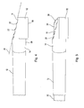
- a in the FIGS. 1 to 7 represented inventive medical instrument for separating tissue and cartilage is designated in its entirety by the reference numeral 10.
- the instrument 10 has an elongated straight hollow outer shaft 12.
- the first window 16 has a peripheral edge 18, which is designed as a cutting edge 20.
- jaws 22 From the cutting edge 20 are jaws 22 high, like that in particular Fig. 3 . 4 and 5 is apparent.
- the peripheral edge 18 is in the region of an oblique section 24, as in Fig. 4 is indicated.
- This oblique section 24 is inclined radially inward from the proximal to the distal, so that the first window 16 has an approximately oval cross-section.
- the inclination of the oblique cut 24 is, like that Fig. 4 It can be seen that at the distal vertex less than half of a diameter is cut off.
- the prongs 22 can be worked out.
- the inner shaft 32 is also formed as an elongated hollow shaft whose outer diameter corresponds approximately to the clear inner diameter of the outer shaft 12.
- the inner shaft 32 is circumferentially approximately evenly distributed with three openings 36, 37 and 38 provided.
- Each of the openings 36, 37 and 38 is provided at its peripheral edge with a peripheral cutting edge 40, wherein only the cutting edge 40 of the opening 36 is provided with a reference numeral.
- the length of the inner shaft 32 is selected so that it can be pushed completely into the outer shaft 12 from the proximal end.
- the cutting edges 40 of the openings 36 etc. rotate with and run on the also formed as a cutting edge 20 edge 18 of the first window 16 in the outer shaft 12 over. This scissors cuts then take place.
- the inner shaft 32 has a connecting piece 42, via which the inner shaft 32 can be connected to a vacuum source 44, as in FIG Fig. 1 is indicated.
- connecting piece 42 still radially projecting coupling pin 46, via which a coupling piece of a drive not shown here can be brought, through which the inner shaft 32 can be rotated in the outer shaft 12.
- the outer shaft 12 has a coupling piece 26 at its proximal end.
- the inner shaft 32 can be pushed so far from the proximal to the distal through the coupling piece 26 until the connecting piece 42 has fit inside the sleeve-like body of the coupling piece 26, as is the case Fig. 1 is apparent. As a result, the inner shaft 32 is guided and received in the outer shaft 12.
- the distal region of the instrument 10 operates as a so-called "shaver blade”.
- the inner shaft 32 When rotating the inner shaft 32 separate the cutting edges 40 of the openings 36, 37, 38 in cooperation with the cutting edge 20 of the first window 16 in the outer shaft corresponding tissue pieces and they are sucked into the interior of the inner shaft 32 through the openings 36, 37, 38 and dissipated.
- the negative pressure ensures that the tissue parts to be separated are sucked laterally against the first window 16 in the outer shaft 12 and then separated.
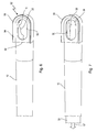
- This further window 50 is surrounded by a curette 52 which has the contour 54 of a proximally open U '.
- the radially outer U-edge is formed as a sharp separating edge 56. As in particular from 4 and 5 can be seen, this separating edge 56 projects laterally beyond the outer surface 58 of the outer shaft 12.
- cartilage pieces even relatively large pieces of cartilage, are now separated from the separating edge 56, they are moved by the negative pressure source 44 through the further window 50 in the direction of the interior of the outer shaft 12 and then by the rotating cutting edges 40 of the openings 36, 37 and 38 in FIG Interior shaft cut into the smallest pieces. If these pieces are then sufficiently small, they can be sucked and discharged via the openings 36, 37 and 38 in the inner shaft 32.
- the separating edge 56 may be formed as a closed oval around the oval window 50 circumferential edge.
- this separating edge 56 is open to the proximal end.
- the surgeon can, for example, first push the distally closed region of the separating edge 56 against the defect site and position it so that it comes to rest somewhat behind the area of the defect site seen by the surgeon and surrounds this region. Then he can gradually press the separating edge 56 into the cartilaginous tissue. He can at least partially see this via the proximal end open end 59 of the profile.
- Fig. 8 is shown very schematically a femur 70 in the region of a knee joint.
- defect 71 which was first processed with the "Shaver Blade" of the instrument 10.
- a relatively blurred peripheral edge 72 is formed on the surrounding tissue of the bone 70.
- the bone material 74 is already exposed.
- Fig. 9 now shows the defect 71 after the curette 52 has been applied, pressed in and the marginal cartilage tissue has been removed down to the bone material 74.
- the smooth and sharp separating edge 56 of the curette 52 produced a sharp edge 76, which protrudes at approximately the right angle from the bone surface and corresponds to its geometry.
- the contour 54 of the separating edge 56 of the curette can also be closed, oval or round.
- the surface of the separating edge can also run correspondingly curved if such defects occur at extremely curved bone sites, so that then the contour of the curette or its separating edge 56 can already be adapted to this bone contour.
Claims (15)
- Instrument médical pour la séparation de tissu et de cartilage avec un arbre externe (12) qui présente dans la région de son extrémité distale (14) au moins une première fenêtre (16) avec au moins une lame (20), avec un arbre interne (32) reçu dans l'arbre externe (12) pouvant tourner autour de son axe longitudinal (33) qui présente à son extrémité distale (34), dans la région de la première fenêtre (16) de l'arbre externe (12), au moins une ouverture (36, 37, 38) avec une lame (40) qui coopère de manière coupante avec l'au moins une lame (20) de l'arbre externe (12), dans lequel l'arbre interne creux (32) peut être raccordé à une source de dépression (44), dans lequel
une autre fenêtre (50) est évidée sur l'arbre externe (12) dans la région de l'extrémité distale (14), caractérisé en ce que l'autre fenêtre (50) est entourée par une curette (52) à l'extrémité distale de l'arbre externe. - Instrument médical selon la revendication 1, caractérisé en ce que la curette (52) fait saillie radialement d'une surface externe (58) de l'arbre externe (12).
- Instrument médical selon la revendication 1 ou 2, caractérisé en ce que le contour (54) de la curette (52) est en forme de U, vu radialement de l'extérieur sur l'arbre externe (12).
- Instrument médical selon la revendication 3, caractérisé en ce que l'extrémité ouverte (59) du contour en U se situe du côté proximal.
- Instrument médical selon une des revendications 1 à 4, caractérisé en ce qu'une arête de séparation (56) de la curette (52) se situe dans un plan.
- Instrument médical selon la revendication 5, caractérisé en ce que l'arête de séparation (56) de la curette (52) fait saillie d'une telle hauteur radialement de la surface externe (58) de l'arbre externe (12) qui correspond au moins à l'épaisseur d'une couche de cartilage à séparer.
- Instrument médical selon une des revendications 1 à 6, caractérisé en ce que l'arbre externe (12) présente une seule première fenêtre (16) qui est disposée de manière diamétralement opposée à la curette (52).
- Instrument médical selon une des revendications 1 à 7, caractérisé en ce que la première fenêtre (16) est réalisée dans l'arbre externe (12) par une coupe en biais (24) de l'arbre externe creux (12) inclinée radialement vers l'intérieur de la direction proximale vers la direction distale.
- Instrument médical selon la revendication 8, caractérisé en ce que l'arbre interne (32) dépasse de la première fenêtre (16) dans la région de la coupe en biais (24).
- Instrument médical selon une des revendications 1 à 9, caractérisé en ce qu'une arête périphérique (18) de la première fenêtre (16) présente des dents (22) élevées de cette arête périphérique (18) dans l'arbre externe (12).
- Instrument médical selon une des revendications 1 à 10, caractérisé en ce que l'arbre interne rotatif (32) présente plusieurs ouvertures (36, 37, 38).
- Instrument médical selon la revendication 11, caractérisé en ce que l'arbre interne (32) présente trois ouvertures (36, 37, 38).
- Instrument médical selon une des revendications 1 à 12, caractérisé en ce que l'arbre externe (12) présente à l'extrémité proximale une pièce d'accouplement (26) à travers laquelle l'arbre interne (32) peut être guidé de la direction proximale.
- Instrument médical selon une des revendications 1 à 13, caractérisé en ce que l'arbre interne (32) présente à l'extrémité proximale une pièce de raccordement (42) par le biais de laquelle il peut être relié à une source de dépression (44).
- Instrument médical selon la revendication 14, caractérisé en ce que la pièce de raccordement (42) peut être accouplée à un entraînement qui fait tourner l'arbre interne (32) autour de son axe longitudinal (33) par rapport à l'arbre externe stationnaire (12) par le biais d'éléments d'accouplement (46).
Applications Claiming Priority (1)
| Application Number | Priority Date | Filing Date | Title |
|---|---|---|---|
| DE102012103153A DE102012103153A1 (de) | 2012-04-12 | 2012-04-12 | Medizinisches Instrument zum Abtrennen von Gewebe und Knorpel |
Publications (2)
| Publication Number | Publication Date |
|---|---|
| EP2679174A1 EP2679174A1 (fr) | 2014-01-01 |
| EP2679174B1 true EP2679174B1 (fr) | 2014-11-19 |
Family
ID=48095655
Family Applications (1)
| Application Number | Title | Priority Date | Filing Date |
|---|---|---|---|
| EP13163333.1A Active EP2679174B1 (fr) | 2012-04-12 | 2013-04-11 | Instrument médical pour la séparation de tissus et de cartilages |
Country Status (3)
| Country | Link |
|---|---|
| US (1) | US9095354B2 (fr) |
| EP (1) | EP2679174B1 (fr) |
| DE (1) | DE102012103153A1 (fr) |
Families Citing this family (6)
| Publication number | Priority date | Publication date | Assignee | Title |
|---|---|---|---|---|
| US9649124B2 (en) * | 2014-01-16 | 2017-05-16 | James K Brannon | Curved blade tissue shaver |
| US9055967B1 (en) * | 2014-11-07 | 2015-06-16 | Oscar R Polo | Tissue severing device having dual reciprocating looped blades and methods of use |
| US10085830B2 (en) * | 2016-05-13 | 2018-10-02 | Medos International Sarl | Device, system, and method for delivery of a tissue fixation device |
| US11672593B2 (en) * | 2018-04-23 | 2023-06-13 | RELIGN Corporation | Arthroscopic devices and methods |
| DE102020133579B3 (de) * | 2020-12-15 | 2022-04-28 | Eberle Gmbh & Co. Kg | Chirurgisches Instrument zur Entnahme von Knorpelgewebe und/oder Knochenmaterial |
| DE102021120171A1 (de) | 2021-08-03 | 2023-02-09 | Eberle Gmbh & Co. Kg | Chirurgisches Instrument zur Entnahme von Weichgewebe, Knorpelgewebe und/oder Knochenmaterial |
Family Cites Families (11)
| Publication number | Priority date | Publication date | Assignee | Title |
|---|---|---|---|---|
| US4811734A (en) * | 1987-08-13 | 1989-03-14 | Baxter Travenol Laboratories, Inc. | Surgical cutting instrument |
| US5792167A (en) * | 1996-09-13 | 1998-08-11 | Stryker Corporation | Surgical irrigation pump and tool system |
| US5964777A (en) * | 1997-12-11 | 1999-10-12 | Smith & Nephew, Inc. | Surgical cutting instrument |
| US6419684B1 (en) * | 2000-05-16 | 2002-07-16 | Linvatec Corporation | End-cutting shaver blade for axial resection |
| US6610059B1 (en) * | 2002-02-25 | 2003-08-26 | Hs West Investments Llc | Endoscopic instruments and methods for improved bubble aspiration at a surgical site |
| EP1558152B1 (fr) * | 2002-10-25 | 2010-10-27 | HydroCision, Inc. | Dispositifs chirurgicaux permettant une manipulation des tissus assistee par jet liquide |
| DE102006034756A1 (de) * | 2006-07-24 | 2008-01-31 | Karl Storz Gmbh & Co. Kg | Medizinisches Instrument zum Schneiden von Gewebe |
| US20080208194A1 (en) * | 2007-02-13 | 2008-08-28 | Christine Bickenbach | Double cut shaver |
| WO2010138944A2 (fr) * | 2009-05-28 | 2010-12-02 | Angiotech Pharmaceuticals Inc. | Jeu d'aiguilles pour dispositif de biopsie |
| US8409235B2 (en) * | 2010-04-30 | 2013-04-02 | Medtronic Xomed, Inc. | Rotary cutting tool with improved cutting and reduced clogging on soft tissue and thin bone |
| US20130110147A1 (en) * | 2011-10-31 | 2013-05-02 | Randy Dame | Tube set for a rotary tissue cutter with curved inner blade |
-
2012
- 2012-04-12 DE DE102012103153A patent/DE102012103153A1/de not_active Withdrawn
-
2013
- 2013-04-11 EP EP13163333.1A patent/EP2679174B1/fr active Active
- 2013-04-12 US US13/862,097 patent/US9095354B2/en active Active
Also Published As
| Publication number | Publication date |
|---|---|
| US20130274751A1 (en) | 2013-10-17 |
| EP2679174A1 (fr) | 2014-01-01 |
| DE102012103153A1 (de) | 2013-10-17 |
| US9095354B2 (en) | 2015-08-04 |
Similar Documents
| Publication | Publication Date | Title |
|---|---|---|
| DE2848314C2 (de) | Chirurgisches Instrument | |
| EP2679174B1 (fr) | Instrument médical pour la séparation de tissus et de cartilages | |
| DE69634612T2 (de) | Chirurgisches schneidegerät abnehmbar | |
| DE60018712T2 (de) | Chirurgischer bohrer | |
| EP2096982B1 (fr) | Dispositif et procédé pour intervention minimale invasive sur la colonne vertébrale | |
| DE69635564T2 (de) | Gerät zum Einsetzen von Rückenwirbelimplantaten | |
| EP2521518B1 (fr) | Dispositif pour couper et aspirer des tissus | |
| DE202011111061U1 (de) | Orthopädische Fräsvorrichtung zur Knochenpräparation, insbesondere Gelenkpräparation | |
| EP1005293A1 (fr) | Instrument medical pour retirer par voie endoscopique la veine saphene interne | |
| DE102011013888A1 (de) | Medizinisches Einstechwerkzeug | |
| EP1203565A1 (fr) | Dispositif de biopsie endoscopique, notamment pour cartilage | |
| EP0969772A1 (fr) | Spatule-dissecteur a ecartement expansible | |
| AT509761B1 (de) | Knochenbiopsiefräser | |
| EP3641670B1 (fr) | Kit d'instruments pour des opérations rachidiennes | |
| DE102018009476B3 (de) | Excisionsskalpell | |
| DE112017000316T5 (de) | Einziehbares chirurgisches Handinstrument | |
| EP3756554A1 (fr) | Scalpel d'excérsion | |
| EP0942684B1 (fr) | Pince medicale | |
| DE4406045C1 (de) | Gewebsresektorzange zur Behandlung von Strichkanalstenosen | |
| DE19703698C1 (de) | Stenosestanze | |
| EP1755467B1 (fr) | Dispositif pour decouper des zones tissulaires sur des os | |
| DE102007002855A1 (de) | Probenahmevorrichtung, insbesondere Biopsienadel | |
| WO2021069594A2 (fr) | Instrument chirurgical, procédé de production d'un instrument chirurgical et utilisation d'une articulation rotoïde pour former un outil de coupe d'un instrument chirurgical | |
| DE102022122678A1 (de) | Schaberanordnung für ein chirurgisches instrument | |
| DE202023102729U1 (de) | Drehschneidender Knochenmeißel |
Legal Events
| Date | Code | Title | Description |
|---|---|---|---|
| PUAI | Public reference made under article 153(3) epc to a published international application that has entered the european phase |
Free format text: ORIGINAL CODE: 0009012 |
|
| AK | Designated contracting states |
Kind code of ref document: A1 Designated state(s): AL AT BE BG CH CY CZ DE DK EE ES FI FR GB GR HR HU IE IS IT LI LT LU LV MC MK MT NL NO PL PT RO RS SE SI SK SM TR |
|
| 17P | Request for examination filed |
Effective date: 20140115 |
|
| RBV | Designated contracting states (corrected) |
Designated state(s): AL AT BE BG CH CY CZ DE DK EE ES FI FR GB GR HR HU IE IS IT LI LT LU LV MC MK MT NL NO PL PT RO RS SE SI SK SM TR |
|
| RIC1 | Information provided on ipc code assigned before grant |
Ipc: A61B 17/16 20060101AFI20140318BHEP Ipc: A61B 17/3207 20060101ALI20140318BHEP Ipc: A61B 17/32 20060101ALI20140318BHEP |
|
| GRAP | Despatch of communication of intention to grant a patent |
Free format text: ORIGINAL CODE: EPIDOSNIGR1 |
|
| INTG | Intention to grant announced |
Effective date: 20140605 |
|
| GRAS | Grant fee paid |
Free format text: ORIGINAL CODE: EPIDOSNIGR3 |
|
| GRAA | (expected) grant |
Free format text: ORIGINAL CODE: 0009210 |
|
| AK | Designated contracting states |
Kind code of ref document: B1 Designated state(s): AL AT BE BG CH CY CZ DE DK EE ES FI FR GB GR HR HU IE IS IT LI LT LU LV MC MK MT NL NO PL PT RO RS SE SI SK SM TR |
|
| REG | Reference to a national code |
Ref country code: GB Ref legal event code: FG4D Free format text: NOT ENGLISH |
|
| REG | Reference to a national code |
Ref country code: CH Ref legal event code: EP |
|
| REG | Reference to a national code |
Ref country code: AT Ref legal event code: REF Ref document number: 696532 Country of ref document: AT Kind code of ref document: T Effective date: 20141215 |
|
| REG | Reference to a national code |
Ref country code: IE Ref legal event code: FG4D Free format text: LANGUAGE OF EP DOCUMENT: GERMAN |
|
| REG | Reference to a national code |
Ref country code: DE Ref legal event code: R096 Ref document number: 502013000196 Country of ref document: DE Effective date: 20141224 |
|
| REG | Reference to a national code |
Ref country code: NL Ref legal event code: VDEP Effective date: 20141119 |
|
| REG | Reference to a national code |
Ref country code: LT Ref legal event code: MG4D |
|
| PG25 | Lapsed in a contracting state [announced via postgrant information from national office to epo] |
Ref country code: LT Free format text: LAPSE BECAUSE OF FAILURE TO SUBMIT A TRANSLATION OF THE DESCRIPTION OR TO PAY THE FEE WITHIN THE PRESCRIBED TIME-LIMIT Effective date: 20141119 Ref country code: IS Free format text: LAPSE BECAUSE OF FAILURE TO SUBMIT A TRANSLATION OF THE DESCRIPTION OR TO PAY THE FEE WITHIN THE PRESCRIBED TIME-LIMIT Effective date: 20150319 Ref country code: FI Free format text: LAPSE BECAUSE OF FAILURE TO SUBMIT A TRANSLATION OF THE DESCRIPTION OR TO PAY THE FEE WITHIN THE PRESCRIBED TIME-LIMIT Effective date: 20141119 Ref country code: PT Free format text: LAPSE BECAUSE OF FAILURE TO SUBMIT A TRANSLATION OF THE DESCRIPTION OR TO PAY THE FEE WITHIN THE PRESCRIBED TIME-LIMIT Effective date: 20150319 Ref country code: ES Free format text: LAPSE BECAUSE OF FAILURE TO SUBMIT A TRANSLATION OF THE DESCRIPTION OR TO PAY THE FEE WITHIN THE PRESCRIBED TIME-LIMIT Effective date: 20141119 Ref country code: NL Free format text: LAPSE BECAUSE OF FAILURE TO SUBMIT A TRANSLATION OF THE DESCRIPTION OR TO PAY THE FEE WITHIN THE PRESCRIBED TIME-LIMIT Effective date: 20141119 Ref country code: NO Free format text: LAPSE BECAUSE OF FAILURE TO SUBMIT A TRANSLATION OF THE DESCRIPTION OR TO PAY THE FEE WITHIN THE PRESCRIBED TIME-LIMIT Effective date: 20150219 |
|
| PG25 | Lapsed in a contracting state [announced via postgrant information from national office to epo] |
Ref country code: GR Free format text: LAPSE BECAUSE OF FAILURE TO SUBMIT A TRANSLATION OF THE DESCRIPTION OR TO PAY THE FEE WITHIN THE PRESCRIBED TIME-LIMIT Effective date: 20150220 Ref country code: LV Free format text: LAPSE BECAUSE OF FAILURE TO SUBMIT A TRANSLATION OF THE DESCRIPTION OR TO PAY THE FEE WITHIN THE PRESCRIBED TIME-LIMIT Effective date: 20141119 Ref country code: HR Free format text: LAPSE BECAUSE OF FAILURE TO SUBMIT A TRANSLATION OF THE DESCRIPTION OR TO PAY THE FEE WITHIN THE PRESCRIBED TIME-LIMIT Effective date: 20141119 Ref country code: PL Free format text: LAPSE BECAUSE OF FAILURE TO SUBMIT A TRANSLATION OF THE DESCRIPTION OR TO PAY THE FEE WITHIN THE PRESCRIBED TIME-LIMIT Effective date: 20141119 Ref country code: RS Free format text: LAPSE BECAUSE OF FAILURE TO SUBMIT A TRANSLATION OF THE DESCRIPTION OR TO PAY THE FEE WITHIN THE PRESCRIBED TIME-LIMIT Effective date: 20141119 Ref country code: SE Free format text: LAPSE BECAUSE OF FAILURE TO SUBMIT A TRANSLATION OF THE DESCRIPTION OR TO PAY THE FEE WITHIN THE PRESCRIBED TIME-LIMIT Effective date: 20141119 Ref country code: CY Free format text: LAPSE BECAUSE OF FAILURE TO SUBMIT A TRANSLATION OF THE DESCRIPTION OR TO PAY THE FEE WITHIN THE PRESCRIBED TIME-LIMIT Effective date: 20141119 |
|
| PG25 | Lapsed in a contracting state [announced via postgrant information from national office to epo] |
Ref country code: RO Free format text: LAPSE BECAUSE OF FAILURE TO SUBMIT A TRANSLATION OF THE DESCRIPTION OR TO PAY THE FEE WITHIN THE PRESCRIBED TIME-LIMIT Effective date: 20141119 Ref country code: CZ Free format text: LAPSE BECAUSE OF FAILURE TO SUBMIT A TRANSLATION OF THE DESCRIPTION OR TO PAY THE FEE WITHIN THE PRESCRIBED TIME-LIMIT Effective date: 20141119 Ref country code: EE Free format text: LAPSE BECAUSE OF FAILURE TO SUBMIT A TRANSLATION OF THE DESCRIPTION OR TO PAY THE FEE WITHIN THE PRESCRIBED TIME-LIMIT Effective date: 20141119 Ref country code: SK Free format text: LAPSE BECAUSE OF FAILURE TO SUBMIT A TRANSLATION OF THE DESCRIPTION OR TO PAY THE FEE WITHIN THE PRESCRIBED TIME-LIMIT Effective date: 20141119 Ref country code: DK Free format text: LAPSE BECAUSE OF FAILURE TO SUBMIT A TRANSLATION OF THE DESCRIPTION OR TO PAY THE FEE WITHIN THE PRESCRIBED TIME-LIMIT Effective date: 20141119 |
|
| REG | Reference to a national code |
Ref country code: DE Ref legal event code: R097 Ref document number: 502013000196 Country of ref document: DE |
|
| PLBE | No opposition filed within time limit |
Free format text: ORIGINAL CODE: 0009261 |
|
| STAA | Information on the status of an ep patent application or granted ep patent |
Free format text: STATUS: NO OPPOSITION FILED WITHIN TIME LIMIT |
|
| 26N | No opposition filed |
Effective date: 20150820 |
|
| PG25 | Lapsed in a contracting state [announced via postgrant information from national office to epo] |
Ref country code: MC Free format text: LAPSE BECAUSE OF FAILURE TO SUBMIT A TRANSLATION OF THE DESCRIPTION OR TO PAY THE FEE WITHIN THE PRESCRIBED TIME-LIMIT Effective date: 20141119 Ref country code: LU Free format text: LAPSE BECAUSE OF FAILURE TO SUBMIT A TRANSLATION OF THE DESCRIPTION OR TO PAY THE FEE WITHIN THE PRESCRIBED TIME-LIMIT Effective date: 20150411 |
|
| REG | Reference to a national code |
Ref country code: IE Ref legal event code: MM4A |
|
| PG25 | Lapsed in a contracting state [announced via postgrant information from national office to epo] |
Ref country code: SI Free format text: LAPSE BECAUSE OF FAILURE TO SUBMIT A TRANSLATION OF THE DESCRIPTION OR TO PAY THE FEE WITHIN THE PRESCRIBED TIME-LIMIT Effective date: 20141119 |
|
| REG | Reference to a national code |
Ref country code: FR Ref legal event code: PLFP Year of fee payment: 4 |
|
| PG25 | Lapsed in a contracting state [announced via postgrant information from national office to epo] |
Ref country code: IE Free format text: LAPSE BECAUSE OF NON-PAYMENT OF DUE FEES Effective date: 20150411 |
|
| REG | Reference to a national code |
Ref country code: CH Ref legal event code: PL |
|
| PG25 | Lapsed in a contracting state [announced via postgrant information from national office to epo] |
Ref country code: MT Free format text: LAPSE BECAUSE OF FAILURE TO SUBMIT A TRANSLATION OF THE DESCRIPTION OR TO PAY THE FEE WITHIN THE PRESCRIBED TIME-LIMIT Effective date: 20141119 |
|
| PG25 | Lapsed in a contracting state [announced via postgrant information from national office to epo] |
Ref country code: CH Free format text: LAPSE BECAUSE OF NON-PAYMENT OF DUE FEES Effective date: 20160430 Ref country code: LI Free format text: LAPSE BECAUSE OF NON-PAYMENT OF DUE FEES Effective date: 20160430 |
|
| REG | Reference to a national code |
Ref country code: FR Ref legal event code: PLFP Year of fee payment: 5 |
|
| PG25 | Lapsed in a contracting state [announced via postgrant information from national office to epo] |
Ref country code: BG Free format text: LAPSE BECAUSE OF FAILURE TO SUBMIT A TRANSLATION OF THE DESCRIPTION OR TO PAY THE FEE WITHIN THE PRESCRIBED TIME-LIMIT Effective date: 20141119 Ref country code: HU Free format text: LAPSE BECAUSE OF FAILURE TO SUBMIT A TRANSLATION OF THE DESCRIPTION OR TO PAY THE FEE WITHIN THE PRESCRIBED TIME-LIMIT; INVALID AB INITIO Effective date: 20130411 |
|
| PG25 | Lapsed in a contracting state [announced via postgrant information from national office to epo] |
Ref country code: BE Free format text: LAPSE BECAUSE OF NON-PAYMENT OF DUE FEES Effective date: 20150430 |
|
| PG25 | Lapsed in a contracting state [announced via postgrant information from national office to epo] |
Ref country code: TR Free format text: LAPSE BECAUSE OF FAILURE TO SUBMIT A TRANSLATION OF THE DESCRIPTION OR TO PAY THE FEE WITHIN THE PRESCRIBED TIME-LIMIT Effective date: 20141119 |
|
| REG | Reference to a national code |
Ref country code: DE Ref legal event code: R081 Ref document number: 502013000196 Country of ref document: DE Owner name: KARL STORZ SE & CO. KG INTELLECTUAL PROPERTY, DE Free format text: FORMER OWNER: KARL STORZ GMBH & CO. KG, 78532 TUTTLINGEN, DE Ref country code: DE Ref legal event code: R082 Ref document number: 502013000196 Country of ref document: DE Representative=s name: WITTE, WELLER & PARTNER PATENTANWAELTE MBB, DE Ref country code: DE Ref legal event code: R081 Ref document number: 502013000196 Country of ref document: DE Owner name: KARL STORZ SE & CO. KG, DE Free format text: FORMER OWNER: KARL STORZ GMBH & CO. KG, 78532 TUTTLINGEN, DE |
|
| REG | Reference to a national code |
Ref country code: FR Ref legal event code: PLFP Year of fee payment: 6 |
|
| PG25 | Lapsed in a contracting state [announced via postgrant information from national office to epo] |
Ref country code: SM Free format text: LAPSE BECAUSE OF FAILURE TO SUBMIT A TRANSLATION OF THE DESCRIPTION OR TO PAY THE FEE WITHIN THE PRESCRIBED TIME-LIMIT Effective date: 20141119 |
|
| PG25 | Lapsed in a contracting state [announced via postgrant information from national office to epo] |
Ref country code: MK Free format text: LAPSE BECAUSE OF FAILURE TO SUBMIT A TRANSLATION OF THE DESCRIPTION OR TO PAY THE FEE WITHIN THE PRESCRIBED TIME-LIMIT Effective date: 20141119 |
|
| PG25 | Lapsed in a contracting state [announced via postgrant information from national office to epo] |
Ref country code: AL Free format text: LAPSE BECAUSE OF FAILURE TO SUBMIT A TRANSLATION OF THE DESCRIPTION OR TO PAY THE FEE WITHIN THE PRESCRIBED TIME-LIMIT Effective date: 20141119 |
|
| REG | Reference to a national code |
Ref country code: AT Ref legal event code: MM01 Ref document number: 696532 Country of ref document: AT Kind code of ref document: T Effective date: 20180411 |
|
| PG25 | Lapsed in a contracting state [announced via postgrant information from national office to epo] |
Ref country code: AT Free format text: LAPSE BECAUSE OF NON-PAYMENT OF DUE FEES Effective date: 20180411 |
|
| PGFP | Annual fee paid to national office [announced via postgrant information from national office to epo] |
Ref country code: FR Payment date: 20230321 Year of fee payment: 11 |
|
| PGFP | Annual fee paid to national office [announced via postgrant information from national office to epo] |
Ref country code: IT Payment date: 20230322 Year of fee payment: 11 Ref country code: GB Payment date: 20230321 Year of fee payment: 11 |
|
| P01 | Opt-out of the competence of the unified patent court (upc) registered |
Effective date: 20230527 |
|
| PGFP | Annual fee paid to national office [announced via postgrant information from national office to epo] |
Ref country code: DE Payment date: 20230321 Year of fee payment: 11 |