EP1558152B1 - Dispositifs chirurgicaux permettant une manipulation des tissus assistee par jet liquide - Google Patents
Dispositifs chirurgicaux permettant une manipulation des tissus assistee par jet liquide Download PDFInfo
- Publication number
- EP1558152B1 EP1558152B1 EP03809652A EP03809652A EP1558152B1 EP 1558152 B1 EP1558152 B1 EP 1558152B1 EP 03809652 A EP03809652 A EP 03809652A EP 03809652 A EP03809652 A EP 03809652A EP 1558152 B1 EP1558152 B1 EP 1558152B1
- Authority
- EP
- European Patent Office
- Prior art keywords
- tissue
- instrument
- surgical
- liquid jet
- jet
- Prior art date
- Legal status (The legal status is an assumption and is not a legal conclusion. Google has not performed a legal analysis and makes no representation as to the accuracy of the status listed.)
- Expired - Lifetime
Links
Images


Classifications
-
- A—HUMAN NECESSITIES
- A61—MEDICAL OR VETERINARY SCIENCE; HYGIENE
- A61B—DIAGNOSIS; SURGERY; IDENTIFICATION
- A61B17/00—Surgical instruments, devices or methods, e.g. tourniquets
- A61B17/32—Surgical cutting instruments
- A61B17/3203—Fluid jet cutting instruments
- A61B17/32037—Fluid jet cutting instruments for removing obstructions from inner organs or blood vessels, e.g. for atherectomy
-
- A—HUMAN NECESSITIES
- A61—MEDICAL OR VETERINARY SCIENCE; HYGIENE
- A61B—DIAGNOSIS; SURGERY; IDENTIFICATION
- A61B17/00—Surgical instruments, devices or methods, e.g. tourniquets
- A61B17/32—Surgical cutting instruments
- A61B17/320016—Endoscopic cutting instruments, e.g. arthroscopes, resectoscopes
- A61B17/32002—Endoscopic cutting instruments, e.g. arthroscopes, resectoscopes with continuously rotating, oscillating or reciprocating cutting instruments
-
- A—HUMAN NECESSITIES
- A61—MEDICAL OR VETERINARY SCIENCE; HYGIENE
- A61M—DEVICES FOR INTRODUCING MEDIA INTO, OR ONTO, THE BODY; DEVICES FOR TRANSDUCING BODY MEDIA OR FOR TAKING MEDIA FROM THE BODY; DEVICES FOR PRODUCING OR ENDING SLEEP OR STUPOR
- A61M3/00—Medical syringes, e.g. enemata; Irrigators
- A61M3/02—Enemata; Irrigators
- A61M3/0279—Cannula; Nozzles; Tips; their connection means
- A61M3/0283—Cannula; Nozzles; Tips; their connection means with at least two inner passageways, a first one for irrigating and a second for evacuating
-
- A—HUMAN NECESSITIES
- A61—MEDICAL OR VETERINARY SCIENCE; HYGIENE
- A61B—DIAGNOSIS; SURGERY; IDENTIFICATION
- A61B17/00—Surgical instruments, devices or methods, e.g. tourniquets
- A61B17/32—Surgical cutting instruments
- A61B17/3203—Fluid jet cutting instruments
-
- A—HUMAN NECESSITIES
- A61—MEDICAL OR VETERINARY SCIENCE; HYGIENE
- A61B—DIAGNOSIS; SURGERY; IDENTIFICATION
- A61B17/00—Surgical instruments, devices or methods, e.g. tourniquets
- A61B17/32—Surgical cutting instruments
- A61B17/3205—Excision instruments
- A61B17/3207—Atherectomy devices working by cutting or abrading; Similar devices specially adapted for non-vascular obstructions
- A61B17/320708—Curettes, e.g. hollow scraping instruments
-
- A—HUMAN NECESSITIES
- A61—MEDICAL OR VETERINARY SCIENCE; HYGIENE
- A61B—DIAGNOSIS; SURGERY; IDENTIFICATION
- A61B17/00—Surgical instruments, devices or methods, e.g. tourniquets
- A61B17/32—Surgical cutting instruments
- A61B17/3205—Excision instruments
- A61B17/3207—Atherectomy devices working by cutting or abrading; Similar devices specially adapted for non-vascular obstructions
- A61B17/320783—Atherectomy devices working by cutting or abrading; Similar devices specially adapted for non-vascular obstructions through side-hole, e.g. sliding or rotating cutter inside catheter
-
- A—HUMAN NECESSITIES
- A61—MEDICAL OR VETERINARY SCIENCE; HYGIENE
- A61B—DIAGNOSIS; SURGERY; IDENTIFICATION
- A61B17/00—Surgical instruments, devices or methods, e.g. tourniquets
- A61B2017/00535—Surgical instruments, devices or methods, e.g. tourniquets pneumatically or hydraulically operated
-
- A—HUMAN NECESSITIES
- A61—MEDICAL OR VETERINARY SCIENCE; HYGIENE
- A61M—DEVICES FOR INTRODUCING MEDIA INTO, OR ONTO, THE BODY; DEVICES FOR TRANSDUCING BODY MEDIA OR FOR TAKING MEDIA FROM THE BODY; DEVICES FOR PRODUCING OR ENDING SLEEP OR STUPOR
- A61M3/00—Medical syringes, e.g. enemata; Irrigators
- A61M3/02—Enemata; Irrigators
- A61M3/0279—Cannula; Nozzles; Tips; their connection means
- A61M3/0287—Cannula; Nozzles; Tips; their connection means with an external liquid collector
Definitions
- the present invention relates to surgical devices utilized for surgical procedures and incorporating liquid jets to assist manipulation of tissue and/or to manipulate tissue, and, more particularly to surgical devices utilizing high pressure liquid jets to cut tissue and/or drive mechanical tissue cutting components and/or remove or assist in removal of tissue from a surgical site.
- Tissue removing or manipulating surgical instruments traditionally utilized in such procedures often include specialized cutting, scooping, grasping, etc. components having particular shapes and orientations configured for specific surgical purposes.
- challenging surgical environments requiring specialized instruments include joints, the nasal cavity, the throat, the skull, the male and female urinary and reproductive tract, etc.
- One particularly challenging environment is the spine, where access to the vertebral disc often requires removal of fibrous cartilaginous tissue and vertebral bone while avoiding contact with the spinal cord, and nerves, veins and arteries embedded within or adjacent to the spinal column.
- tissue cutting/removal instruments can be utilized in one or more of the above-mentioned surgical environments, most such instruments can generally be classified as those whose tissue cutting/removal component is stationary with respect to the rest of the instrument and those with sliding, rotating, or otherwise movable tissue manipulating components. While each class includes many instruments, for illustrative purposes, the term “curette” will be utilized to represent the former class and the term “rongeur” will be utilized to represent the later class. As will be apparent to those skilled in the art based on the description of the invention to follow, many other traditional surgical instruments share one or more of the shortcomings discussed below and would benefit from the disclosed invention.
- a curette is a well-known surgical device typically comprising a handle and a cup-shaped or ring-shaped distal operating end, typically with sharpened, tissue-cutting edges (see FIG. 1 ).
- a curette is typically dragged across and/or pushed into tissue to score and remove tissue.
- a curette is used to remove a softer superficial layer or quantity of tissue from a harder tissue, such as bone.
- An example of use in surgery includes the scraping of cartilage from bony surfaces of the spine to promote fusion of a disc implant to vertebrae.
- a rongeur is an instrument, typically for excising hard tissue, such as cartilage and bone, often characterized by distal end including a mechanical cutting or punching component actuatable by manipulating the handle of the instrument, e.g. by squeezing, scissor action, etc.
- Many rongeurs and bone punches utilized for spine surgery are configured to include a tube having a sharpened distal end that is longitudinally moveable to contact the proximal side of a bone/tissue protrusion and cut/snip/punch the protrusion upon actuation with the handle (see FIG. 12 ).
- US 5,318,518 describes an irrigating catheter for eliminating solids from body organs and hollow body cavities, wherein a cutting edge for cutting material in the organ that is to be treated is provided at the distal end of the irrigating catheter. Further, a nozzle for ejecting irrigating fluid is disposed in a fish mouth-like end section of the catheter.
- US 6,451,017 B1 discloses a series of devices for performing surgical procedures utilizing electrodes for performing electrocautery on a tissue of the body of a patient. Some of the described devices include operable components for forming a liquid cutting jet.
- the present invention is defined in claim 1.
- Surgical instruments are disclosed that utilize high-pressure liquid jets to perform a variety of useful functions.
- surgical instruments are described incorporating one or more liquid jets utilized to contact tissue excised by a non-liquid jet tissue-cutting component of the surgical instrument for the purpose of further cutting the excised tissue and/or fragmenting and/or disaggregating at least a portion of the excised tissue into a plurality of small particles and/or facilitating or assisting removal of excised tissue from a surgical site without the need to remove the instrument from the surgical site.
- a liquid jet of a surgical instrument can be utilized for the purpose of excising tissue of a patient immobilized and/or manipulated by the surgical instrument.
- liquid jet in certain embodiments of such instruments, can be used, for example, as a cutting jet and/or as a power source for a rotary tissue-contacting device, such as a drill or burr abrader.
- the liquid jet provided in the inventive instruments can be used to bring about or speed up the piecewise removal of tissue, for example bone or a nucleus of a spinal disc, by converting at least a portion of a segment of tissue excised with the device into smaller particles in situ and removing them.
- liquid jets of certain of the inventive instruments can facilitate excision of tissue and removal of the excised tissue from the surgical site while requiring less/no movement of the instrument to discharge debris from the operative site, thereby improving the speed and safety of operation and decreasing fatigue and workload for the surgeon. Also disclosed are methods of using certain liquid jet-containing surgical instruments for performing surgical procedures, for example surgical procedures on the spinal column of a patient.
- the surgical instrument comprises: a nozzle that is shaped to form a liquid jet; a pressure lumen configured and positioned to convey a flow of liquid to the nozzle; an evacuation lumen comprising a jet-receiving opening locatable opposite the nozzle to receive at least a portion of the liquid jet emitted from the nozzle, when the instrument is in operation, and which is configured and positioned to convey a flow of liquid away from the jet-receiving opening; and a non-liquid jet tissue-cutting component constructed and positioned to excise tissue during the surgical procedure, wherein the nozzle is positioned, during operation of the instrument, to direct the liquid jet so as to contact tissue excised by the non-fluid jet tissue-cutting component during a surgical procedure.
- the surgical instrument comprises: a nozzle that is shaped to form a liquid jet; a pressure lumen configured and positioned to convey a flow of liquid to the nozzle; an evacuation lumen comprising a jet-receiving opening locatable opposite the nozzle to receive at least a portion of the liquid jet emitted from the nozzle, when the instrument is in operation, and which is configured and positioned to convey a flow of liquid away from the jet-receiving opening; and a non-liquid jet, non-rotating tissue-cutting component constructed and positioned to excise tissue during the surgical procedure.
- the surgical instrument comprises: a non-liquid jet tissue-cutting component constructed and positioned to excise tissue during a surgical procedure; a tissue receptacle configured and positioned to contain tissue excised by the tissue-cutting component; a nozzle that is shaped to form a liquid jet and is positioned to direct the liquid jet so that at least a portion of the liquid jet is contained within the receptacle, when the instrument is in operation; and a pressure lumen configured and positioned to convey a flow of liquid to the nozzle.
- the surgical instrument comprises: a cup-shaped tissue receptacle configured and positioned to contain tissue; a nozzle that is shaped to form a liquid jet and is positioned to direct the liquid jet so that at least a portion of the liquid jet is contained within the receptacle, when the instrument is in operation; and a pressure lumen configured and positioned to convey a flow of liquid to the nozzle.
- the surgical instrument is a curette, a rongeur, a bone punch, bone-cutting forceps, a morcellator, or a surgical micrograsper and comprises: a nozzle that is shaped to form a liquid jet; and a pressure lumen configured and positioned to convey a flow of high-pressure liquid at a pressure of at least 6,9MPa (1,000 psig) to the nozzle.
- the surgical instrument is a curette device comprising: a nozzle that is shaped to form a liquid jet and a pressure lumen configured and positioned to convey a flow of liquid to the nozzle.
- the surgical instrument comprises: a distal end of the instrument adapted to perform a surgical procedure on a patient and comprising a tissue manipulating component configured and positioned to manipulate a tissue of the patient; a proximal end of the instrument having at least a portion thereof configured to be grasped and/or manipulated by an operator, said portion of the proximal end being operatively coupled to the tissue manipulating component of the distal end to facilitate control and actuation of the tissue manipulating component from a non-manipulating configuration to a manipulating configuration by manipulation of said portion of the proximal end by the operator; a nozzle that is shaped to form a liquid jet; and a pressure lumen configured and positioned to convey a flow of liquid to the nozzle, wherein the nozzle is constructed positioned, during operation of the instrument, to direct the liquid jet to fragment and/or disaggregate and/or cut of at least some tissue manipulated by the manipulating component.
- the surgical instrument comprises: a distal end adapted to perform a surgical procedure on a patient and a proximal end adapted to facilitate control of the instrument by an operator; a rotatable tissue-contacting component constructed and arranged for contact with tissue in a surgical operating field and located at the distal end; a nozzle that is shaped to form a liquid jet; a pressure lumen configured and positioned to convey a flow of liquid to the nozzle; a liquid jet-driven rotor configured and positioned with respect to the nozzle to be drivable in rotation by the liquid jet formed by the nozzle and operatively coupled to the rotatable tissue-contacting component, when the instrument is in operation, such that rotation of the liquid jet-driven rotor causes rotation of the rotatable tissue-contacting component, wherein at least one of the rotatable tissue-contacting component and a distal-most end of the surgical instrument is longitudinally movable relative to the other upon manipulation of at least a portion of the proximal end of the instrument by
- surgical instruments can take on many configurations, depending on the particular application and in the particular surgical arena in which they are intended to be used.
- surgical instruments are disclosed that comprise a basic form and functionality similar to well-known and well-accepted surgical handpiece instruments for tissue removal and/or manipulation, except that they are configured to include one or more high pressure liquid jet components configured to assist and/or enhance their traditional functionality and/or provide new functionality.
- the liquid jet-forming components provided according to the invention are configured with respect to the other components of the inventive surgical instruments such that one or more high pressure liquid jets formed by the instruments are positioned and configured to cut and/or fragment and/or disaggregate and/or facilitate removal of excised tissue of a patient.
- the liquid jet acts through direct contact with the tissue, while in other embodiments it acts through utilization of the liquid jet to power other tissue-cutting or tissue-manipulating components of the surgical instrument.
- one or more liquid jets can be provided, such that liquid jets of the instrument can act through both of the above-mentioned modes of action.
- the invention involves incorporating high pressure liquid jet-forming components into surgical instruments designed for use in confined spaces surrounded by delicate tissue; for example, the spine, joints, the nasal cavity, the throat, the skull, the male and female urinary and reproductive tracts, etc.
- inventive features and functionality described below may be readily adapted, using no more than routine skill and experimentation, for use in a wide variety of surgical instruments specifically designed for surgery in the locations described immediately above, and in other locations, which are not specifically called out, described, or illustrated in the figures herein.
- the inventive surgical instruments comprise a surgical handpiece with a body and/or handle designed to be gripped by the hand of an operator during a surgical or medical procedure.
- the surgical instrument could be configured to be operated by a robotic positioning machine or other type of machine-based positioning/manipulation device.
- Such hand pieces can be configured for use in open surgical procedures or, alternatively, can be configured in use in laparoscopic- or endoscopic-type procedures. Rather than being of the form of a hand piece-type instrument, surgical instruments could take on other configurations known to those skilled in the art.
- Surgical instruments described herein typically will typically include a “distal end” and a “proximal end.”
- a “distal end” of a surgical instrument refers to that portion of the instrument that is adapted to perform a surgical procedure on a patient.
- the "distal end” typically includes such structure as a tissue-manipulating component configured and positioned to manipulate a tissue of the patient, which in certain embodiments can comprise a tissue-cutting component.
- a liquid jet-forming nozzle is provided at the distal end of the surgical instrument, as illustrated and described in more detail below. While the distal end is typically located at a position on the instrument farthest from the operator during use, (i.e., a distal-most position), this need not always be the case.
- proximal end of the instrument refers to that portion of the instrument adapted to be controllable by an operator of the instrument.
- the proximal end typically will include a body and/or handle configured and adapted to be grasped by the hand of an operator during use and which may be operably coupled by mechanical, electrical, or other operative coupling, to a tissue-manipulating/cutting component at the distal end of the instrument to facilitate control and/or actuation of such component (e.g., from a non-manipulating configuration to a manipulating configuration) upon manipulation of the handle/body by the operator.
- inventive surgical instruments are typically referred to as including “liquid jet-” forming components or providing one or more “liquid jets.” It should be understood that, while, in certain embodiments use of liquids to form the liquid jet is preferred, in alternative embodiments, surgical instruments according to the invention could utilize fluids other than liquids, such as certain gasses. Accordingly, wherever “liquid” or “liquid jet” is indicated, the terms “fluid” (encompassing both liquids and gasses) and “fluid jet,” respectively, should also be inferred as being equivalent, unless otherwise specified.
- high pressure as descriptive of the liquid provided by the instrument, in forming the liquid jets of certain embodiments of the surgical instruments of the invention refers to the pressure of the liquid, at the position of the jet opening of a liquid jet-forming nozzle of such instrument, being at least about 3,4 MPa (500 psig).
- the high-pressure liquid supplied to a liquid jet nozzle of the instrument will have a pressure of at least 6.9 MPa (1,000 psig), in other embodiments at least 13,8 MPa (2,000 psig), in other embodiments at least 20,7 MPa (3000 psig), in other embodiments at least 34,5 MPa (5,000 psig), in other embodiments at least 68,9 MPa (10,000 psig), in other embodiments at least 103,4 MPa (15,000 psig), in other embodiments at least 206,8 MPa (30,000 psig), and in yet other embodiments up to about 344,7 MPa (50,000 psig), or more.
- the high-pressure liquid supplied to a liquid jet nozzle of the instrument will have a pressure will have a pressure in the range of 13,8-103,4 MPa (2,000-15,000 psig), in other embodiments between 34,5-68,9 MPa (5,000-10,000 psig), in yet other embodiments between 34,5-51,7 MPa (5,000-7,500 psig), and in yet other embodiments between about 13,8-34.5 MPa (2,000 and 5,000 psig).
- Certain embodiments of the inventive surgical instruments incorporating liquid jets are advantageously configured to be utilized in surgical procedures, such as certain surgeries on the spine, involving the excision and removal of tissue from patients in a surgical site surrounded by delicate tissue. Accordingly, in certain such embodiments, the liquid jet functionality provided according to the invention is configured and adapted to be utilized as part of a surgical instrument having a configuration, shape, size and contour specifically adapted for use in such applications.
- An incomplete list of surgical instruments that can be adapted to include a liquid jet-forming component according to the invention, and which constitutes an exemplary list of certain embodiments of surgical instruments provided according to the invention, includes curettes, rongeurs, bone punches, bone-cutting forceps, morcellators, and surgical graspers or micrograspers (such as certain clamps, forceps, etc.).
- instruments in the form of those described above are constructed to include a nozzle that is shaped to form a liquid jet, and a pressure lumen that is configured and positioned to convey a flow of high pressure liquid to the nozzle.
- the inventive surgical instruments are provided with a liquid jet-forming nozzle, that is constructed and positioned within the instrument so as to direct a liquid jet in such a manner that it fragments and/or disaggregates and/or cuts some tissue manipulated by a tissue-manipulating component at the distal end of the instrument, either through direct contact with the tissue or through indirect means, such as by powering a tissue contacting component positioned at the distal end of the instrument.
- the liquid jet-forming nozzle may be positioned at the distal end of the instrument so that it directs the liquid jet so as to impact, cut, and/or fragment and/or disaggregate tissue acted upon by a tissue-manipulating component such as, for example, a cutting blade, grinding burr, tissue punch, forceps, clamp, grasper, etc.
- the liquid jet-forming nozzle may be positioned within the instrument such that the liquid jet formed by the nozzle does not contact tissue but, rather, is utilized as a source of force and energy for powering a tissue cutting component at the distal end of the instrument.
- tissue manipulating component refers to any structure that is able to bring about a change in at least one physical property of tissue by applying a physical or non-physical force (e.g., electrical energy, electromagnetic radiation, etc.).
- tissue manipulating components that can be utilized in some surgical instruments include components configured to cut, grasp, excise, grind, puncture, or burn tissue in a surgical field.
- surgical instruments include a tissue-manipulating component that comprises a non-liquid jet tissue-cutting component that is constructed and positioned to excise tissue during a surgical procedure.
- tissue-manipulating component that comprises a non-liquid jet tissue-cutting component that is constructed and positioned to excise tissue during a surgical procedure.
- Such instruments are exemplified by, for example, sharpened cutting curettes, certain rongeurs, bone punches, etc.
- a "non-liquid jet tissue-cutting component,” as used herein, refers to essentially any component configured and provided for cutting tissue, other than by impacting the tissue with a high pressure liquid jet. Examples include, but are not limited to, mechanical cutters such as blades, piercing devices, scissors, punchers, grinders, shavers, etc., and non-mechanical tissue cutters such as electrosurgical electrodes, lasers, etc.
- the non-liquid jet tissue-cutting component is stationery and in a fixed positional relationship to the handle/body and the rest of the surgical instrument (e.g. as in typical curettes), while, in other instruments, the non-liquid jet tissue-cutting component can be configured to be movable with respect to the body/handle or some other portion of the instrument (e.g. as in certain rongeurs, bone punches, etc.). In certain such embodiments, the non-liquid jet tissue-cutting component will be longitudinally moveable within the instrument (e.g.
- the nozzle of the instrument will be positioned, at least during operation of the instrument, to direct a liquid jet formed by the nozzle so that it contacts tissue excised by a non-liquid jet tissue-cutting component of the instrument during the surgical procedure.
- Such contact by the liquid jet can, in certain embodiments, do either or both of enhance the cutting action of the non-liquid jet tissue-cutting component and facilitate disaggregation of tissue excised by the non-liquid jet tissue-cutting component.
- the liquid jet can be positioned so that a jet-receiving opening of the evacuation lumen is locatable opposite the nozzle so that it is positioned to receive at least a portion of the liquid jet, and preferably essentially the entire liquid jet, that is emitted from the nozzle when the instrument is in operation.
- the liquid jet can be used to advantageously facilitate and/or assist in removal of both liquid and tissue/debris from the operative site, without the need for removing the entire instrument from the operative site.
- a liquid jet-forming nozzle is positioned within the instrument to enable the liquid jet to contact tissue excised or otherwise manipulated by a tissue-manipulating component at the distal end of the instrument.
- the surgical instruments may also include, at the distal end, a tissue receptacle that is configured and positioned to contain tissue manipulated or excised by the tissue-manipulating component.
- the nozzle of the instrument can be positioned to form a liquid jet having at least a portion thereof that is contained within the receptacle, when the instrument is in operation.
- tissue receptacle refers to any structure that is able to contain, surround, and/or immobilize tissue.
- a tissue receptacle may be cup-shaped, such as is the case in many curette-type instruments.
- the tissue receptacle may be in the shape of a conduit (i.e.
- conduit-shaped such as may be the case for surgical instruments such as certain rongeurs and bone punches, wherein the tissue receptacle can comprise a distal cutting end of a sliding tube (See e.g. Fig.13 and 14 ).
- Conduit-shaped refers to such receptacles being in the shape of a tube, duct, or channel, which is able to permit fluid to flow along and through at least a portion of a lumen of the receptacle.
- curette-type instruments are representative of a class of surgical instruments having a tissue manipulating/cutting component that is stationary with respect to the rest of the instrument, and a spinal rongeur/bone punch of the Kerrison handle type exemplify instruments including tissue manipulating/cutting components that are movable with respect to some part/component of the instrument and which are able to be actuated by an operator via manipulation of a handle or other component at the proximal end of the instrument.
- Patent Number 6,375,635 describes in detail design considerations related to the configuration and sizing of the nozzle, evacuation lumen, liquid jet length and dispersion, materials of construction, liquid pressures for operation, etc. for liquid jets configured to directly contact, cut and/or fragment and/or disaggregate tissue and facilitate removal of tissue through an evacuation lumen.
- U.S. Patent Number 6,511,493 and U.S. Patent Application Publication Number 2003/0125660 A1 describe in detail configurations and design considerations for constructing liquid jet impact-driven rotors for powering rotational elements, such as grinding burrs, drills, etc. in surgical instruments.
- curette 100 includes a proximal end including a handle 102, an elongated neck region 104, and distal end including a tissue-manipulating component 106.
- tissue manipulating component 106 comprises a cup-shaped tissue receptacle.
- the tissue manipulating component at the distal end of the curette may not be cup- or scoop-shaped, as illustrated, but rather could take many other forms.
- component 106 could be ring-shaped.
- curette instruments including a wide variety of differently configured and shaped tissue cutting or tissue manipulating components useful for different purposes and in different surgical procedures are known in the art.
- Cup-shaped tissue receptacle 106 typically will have a sharpened peripheral rim 108 comprising a tissue-cutting component, which can be used to scrape, cut, and/or excise tissue with the instrument.
- the angle 109 formed between the longitudinal axis 110 of cup 106 and longitudinal axis 112 of the proximal portion of neck 104 and handle 102 can vary over a wide range for different instruments. For example, in certain examples, angle 109 could potentially vary within the range from about 0 degrees to about 90 degrees. As illustrated, angle 109 is about 30 degrees.
- width 111 and length 113 of cup 106, and the depth and shape of the receptacle formed by depression 114 of cup 106 can also vary over a wide range depending on the particular instrument and application.
- width 111 and length 113 of cup 106, and the depth of the receptacle formed by depression 114 of cup 106 is within the range of a few millimeters, for example between about 2-8 millimeters.
- the shape of cup 106 is somewhat oval having a length 113 exceeding width 111.
- the shape may be round, square, or a variety of other shapes, as would be apparent to those skilled in the art.
- the surgeon would insert cup 106 into a surgical operating space and scrape, cut, and/or excise tissue within the space so that it is contained within depression 114. After excising tissue, the surgeon would be required to remove the curette from the operating space to remove the excised tissue contained within depression 114 and then reinsert the instrument into the operating field to harvest another piece of tissue.
- Figs. 2-4 illustrate one embodiment of a surgical instrument according to the invention comprising a liquid jet-assisted surgical curette 200.
- Liquid jet curette 200 is similar in overall configuration and size to curette 100.
- Liquid jet curette 200 can include, at its proximal end, a handle 202 and, at its distal end, a cup-shaped tissue manipulating component 206.
- the distal end of curette 200 can also include a nozzle 208 positioned within cup 206 and shaped to form a liquid jet 210.
- Fig. 3 and 4 the distal end of curette 200 can also include a nozzle 208 positioned within cup 206 and shaped to form a liquid jet 210.
- nozzle 208 can be positioned within cup 206 so as to direct liquid jet 210 so that it contacts tissue that is partially contained within cup 206 during operation.
- the curette cup is oval having a length 113 exceeding its width 111, and is sized to fit within the disc space of the vertebra, while allowing the long side of cup edge 108 to efficiently scrape the vertebral end plates.
- Instrument 200 further includes a high-pressure lumen 214 that is configured and positioned to convey a flow of high pressure liquid to nozzle 208.
- pressure lumen 214 over most of its length, is located external to neck 204 and cup 206 portions of the instrument.
- Pressure lumen 214 can enter cup 206 through hole 216 therein, such that nozzle 208 is positioned within tissue receptacle 114 formed by cup 206.
- pressure lumen 214 can be attached to neck 204 and/or cup 206, e.g. via welding, brazing, clamping, etc., to secure the pressure lumen in place and prevent deflection thereof during use.
- this configuration is purely optional and, for example as illustrated in Figs. 6-11 , various other configurations for positioning and securing the pressure lumen within the instrument can be utilized, as would be apparent to those skilled in the art.
- the high pressure liquid conveyed by pressure lumen 214 and utilized to form liquid jet 210 with nozzle 208 will comprise a saline solution or other physiologically compatible liquid.
- Pressure lumen 214, at the proximal end of instrument 200, can be contained within handle 202 and can be in fluid communication with high pressure supply line 220 supplying a source of high pressure liquid.
- the distal end of pressure lumen 214 includes a hole therethrough comprising nozzle 208.
- a hole can be formed, for example, by drilling or etching.
- the illustrated configuration of a hole in the distal end of high pressure lumen 214 forming the nozzle 208 is merely exemplary, and that a wide variety of other techniques for forming the nozzle can be utilized. A number of such techniques and exemplary nozzles formed thereby, which can be used in certain embodiments of the present invention, are described in commonly-owned U.S. Patent Number 6,375,635 .
- the nozzles of the inventive surgical instruments can be formed in the high pressure lumen by any means known to those of ordinary skill in the art.
- the diameter and shape of the jet opening 222 of the nozzle 208 is selected and determined based upon the desired cross-sectional diameter of the liquid jet formed by the instrument and can vary depending upon the particular applications and uses of the instrument. In certain typical embodiments, the diameter of the jet opening of the nozzle can vary within a range of from about 0.001 inch to about 0.01 inch. In one particular embodiment, the diameter of jet opening 222 of nozzle 208 is about 0.005 inch.
- Patent Number 6,375,635 the selection of the nozzle length to diameter ratio and of the degree of the coherence of the liquid jet depend upon factors such as the total length of the liquid jet and the size of an inlet opening or minimum diameter opening of the evacuation lumen, when an evacuation lumen is provided, and whether the instrument is configured to be used in a surrounding air environment or submersed in a liquid environment.
- the reader is referred to the above-referenced commonly owned U.S. Patent Number 6,375,635 for guidance and direction in selecting these and other parameters related to the performance of the liquid jet components provided by the inventive surgical instrument.
- Certain nozzles provided in the instruments of the invention can have a characteristic ratio of nozzle length to minimum jet opening diameter of from between about 1:1 to about 10:1. In one exemplary embodiment, wherein the instrument is designed for use in a surrounding gaseous environment, the nozzle has a characteristic ratio of nozzle length to minimum jet opening diameter of about 3:1.
- nozzle 208 formed in pressure lumen 214 can be configured to emit a jet of liquid into cup 206 of curette device 200.
- High pressure jet 210 can create an entrainment region 224 (dotted lines) of rapidly moving liquid spray as it disperses along its length.
- the jet can be directed to pass through at least a portion of the cup and enters a jet receiving opening 226 of an optional evacuation lumen 228, which, in the illustrated embodiment, comprises a hollow neck portion 204 of the instrument.
- Evacuation lumen 228 can be shaped and positioned such that jet receiving opening 226 is located opposite the nozzle and sized so as to receive at least a portion of the liquid jet emitted from the nozzle. It is preferably further configured and positioned within the instrument to convey a flow of liquid away from the jet receiving opening toward the proximal end of the instrument.
- the cross-sectional diameter of the jet receiving opening can be selected to enable it to be large enough to receive essentially all of the liquid comprising the liquid jet (i.e. at least as large as the diameter of the entrainment region 224 at its point of entry into the evacuation lumen). This can prevent "blow by" and misdirection of the liquid in the entrainment region.
- the evacuation lumen can be sized, configured, and positioned with respect to the nozzle so as to enable fluid and debris entrained by the liquid jet to be evacuated through the evacuation lumen and away from the surgical site without the need to apply an external source of suction, such as a vacuum pump, in fluid communication with evacuation lumen 228. Design considerations enabling such operation are discussed in detail in the above-referenced U.S. Patent Number 6,375,635 .
- Evacuation lumen 228, in this illustrated, exemplary embodiment, comprises a hollow neck portion 204 of the instrument.
- an evacuation lumen could comprise a separate tube affixed to a solid neck portion of a handle, for example neck portion 104 of instrument 100.
- Such an alternative embodiment could also be configured so that the pressure lumen /nozzle combination and/or the evacuation lumen could be separable from the rest of the instrument and disposable after a single use, while the remainder of the instrument could be sterilized and reused.
- an illustrated curette instrument 200 (including a nozzle 208 having a ratio of length to minimum diameter of 3:1 as previously described and operable in an air environment and able to evacuate liquid and debris through evacuation lumen 228 and evacuation tube 230 connected thereto within body 202 of the instrument) has the hollowing design parameters: the pressure of the liquid supplied to the nozzle is between about 34,5 MPa (5,000 psig) and about 103,4 MPa (15,0000 psig); the pressure lumen comprises a stainless steel hypotube having an outer diameter of about 1,14 mm (0.045 inch) and an inner diameter of about 0,51 mm (0,020 inch); the evacuation lumen has smallest diameter opening (which can be a necked region of a constriction in certain embodiments or the jet receiving opening in other embodiments) with a diameter of between about 0,25 mm (0.010 inch) and about 6,35 mm (0.25 inch), in certain particular embodiments between about 0,38 mm (0.015 inch) and about 3,81 mm (0.25 inch), (and in one
- nozzle 208 can be positioned within cup 206 such that the nozzle is located roughly in the center of the cup.
- the relative position of nozzle 208 within cup 206 can be varied.
- the nozzle may be positioned more distally within the cup.
- the nozzle is closer to rim 108 (as shown in Fig. 5 ).
- the nozzle is positioned more proximally and, in certain embodiments, closer to the jet-receiving opening 226 of evacuation lumen 228 ( Fig. 4 ).
- the relative positioning of the jet nozzle within the cup can affect the way in which the liquid jet interacts with tissue within the surgical operating field.
- the jet nozzle be oriented such that the liquid jet is directed so that a central axis of the liquid jet 232 is co-axial with the longitudinal axis 234 of at least a distal portion of evacuation lumen 228, when present. It has been found, in the context of this invention, that such an alignment can reduce the level of misting during operation of the liquid jet curette device in a surrounding air environment.
- nozzle opening 222 can be positioned within curette cup 206 so that the separation distance between nozzle opening 222 and jet receiving opening 226 - defining a corresponding liquid jet length - is not too large. Otherwise, the jet can tend to become blocked by excess tissue in receptacle 114 positioned proximal the nozzle, which can cause clogging of the evacuation tube. By contrast, if the separation distance and jet length is too small, excessive build-up of tissue within receptacle 114 of cup 206 distal the nozzle can occur, which can also lead to clogging of the evacuation lumen.
- examples of a separation distance between jet opening 222 and jet-receiving opening 226, can include between about 1.5 millimeters and about 6 millimeters, between about 2 millimeters and about 4 millimeters and between about 3 millimeters and about 3.5 millimeters.
- liquid jet 210 may itself excise tissue 236 from the patient, or may assist in the excision of the tissue, by directly contacting the tissue while it is still attached to the patient (as shown in Fig. 5 ).
- a device as illustrated in Figs. 2-5 can be used by a surgeon in the same or a similar manner as a traditional curette.
- the surgeon can apply cup 206 to a surgical site of the patient, for example by dragging the curette across a tissue of the patient, using edge 108 of cup 206 (which can be sharpened to form a cutting blade) to excise a piece of tissue from the surgical site.
- the excised tissue will tend to collect in receptacle 114 of curette cup 206.
- Liquid jet 210 can be continuously on during the operation, or, the hand piece 200 or another component of the fluid delivery system may be provided with an on-off switch or other control mechanism to enable the surgeon to turn the jet off and on during operation of the instrument.
- the jet is activated creating a liquid jet 210 originating from nozzle 208 and directed into jet receiving opening 226, with a corresponding entrainment region 224 of jet fluid and fluid/debris entrained by the jet.
- the impact of liquid jet 210 and liquid within entrainment region 224 on tissue within cup 206 can bring about fragmentation and/or disaggregation of tissue contained within the cup.
- the impact forces created by the high pressure liquid jet can at least partially fragment and/or disaggregate the excised tissue and entrained tissue debris.
- the force and momentum of the liquid jet can also, in certain embodiments, facilitate removal from the surgical site of at least a portion of the piece of tissue excised with the instrument by forcing the tissue debris and fluid proximally through evacuation lumen 228 and away from the surgical site.
- evacuation can be assisted via connecting a source of external suction, for example a vacuum pump, in fluid communication with evacuation lumen 228.
- a source of external suction for example a vacuum pump
- the instrument may be configured, as described above and/or in U.S. Patent Number 6,675,635 , to enable evacuation of the liquid comprising the liquid jet and tissue debris, without the need for an external source of suction.
- the action of the liquid jet can create a localized vacuum effect as the jet and entrained fluid flows through receptacle 114 and evacuation lumen 228.
- Such vacuum effect can further serve to assist in removing tissue from the operating site through the evacuation tube.
- Such a vacuum effect can also serve to draw rim 108 of cup 206 into apposition to the tissue being cut.
- such vacuum effect can serve to draw tissue within cup 206 so that liquid jet 210 can contact the tissue within the surgical site directly, so as to enable the jet itself to cut and excise tissue.
- rim 108 of cup 206 need not be sharpened so that it is able to cut tissue.
- the rim and cup can serve only to provide a means for facilitating controlled depth and area cutting by the liquid jet itself.
- the liquid jet can serve both to cut and fragment and/or disaggregate the tissue, simultaneously, while also facilitating the removal of the tissue from the operative site through the evacuation lumen.
- liquid jet-assisted device 200 as compared to conventional curettes such as device 100, is that the surgeon, after excising a first piece of tissue with the device, need not remove the device from the surgical site to remove this tissue from the curette cup. Instead, as discussed above, the action of the liquid jet can facilitate the removal of the piece of tissue from the surgical site and/or disaggregation of the tissue in situ, so that the surgeon may then excise additional pieces of tissue from the patient with the device in a similar fashion without the necessity for removing the device from the patient. As discussed above, this functionality, provided by the present invention, is especially important for surgical procedures performed in delicate, challenging environments, such as, for example the spine of a patient.
- Figs. 6 and 7 illustrate an alternative embodiment for constructing liquid jet-assisted curette device 200 according to the invention. Because the proximal end can be substantially similar to that illustrated previously in Fig. 2 , only a portion of the neck/shaft 204 and distal end is illustrated.
- evacuation lumen 602 and high pressure lumen 604 are separable from, and configured to be contained and immobilized within, a curette cup-providing sleeve component 606.
- Sleeve component 606 can, in certain embodiments, extend proximally only partially along shaft 204, and not all the way to the handle (not shown). In such embodiments, component 606 can be rigidly attached to the pressure and evacuation lumen, e.g.
- component 606 can extend proximally all the way to the handle (not shown) and be rigidly attached to the handle or have a proximal end comprising part of the handle structure itself. In such embodiments, it may not be necessary for the evacuation lumen and/or the pressure lumen to be rigidly attached to and immobilized with respect to component 606. In fact, in certain such embodiments, as discussed below in the context of Figs. 10 and 11 , one or both lumens may be longitudinally movable with respect to component 606 and/or each other to adjust the position of the nozzle and/or evacuation lumen with respect to component 606.
- Component 606 can include, at its distal end, a curette cup 608, which can be similar in shape and size to cup 206.
- Component 606 can be shaped and configured to include longitudinally oriented channels 610 and 612 therein that have a shape and size complimentary to evacuation lumen 602 and high pressure lumen 604, respectively.
- Component 606 can be configured to be clamped or be otherwise affixed to the evacuation lumen and high pressure lumen during operation.
- a nozzle 614 which can comprise a hole in the side wall of high pressure lumen 604, can be configured and positioned to emit a liquid jet 210 creating an entrainment region 224 that at least partially fills jet receiving opening 616 of evacuation lumen 602, during operation.
- such substantial filling of the jet-receiving opening by the entrainment region created by the jet can enhance performance of the device and evacuation of fluid and debris through the evacuation lumen.
- surgical instrument 200 as configured in Figs. 6 - 11 can be constructed by combining two sub-assemblies; sub-assembly 618 comprising a combination of evacuation lumen 602 and high pressure lumen 604, and sub-assembly 620 comprising distal component 606 that includes distally positioned curette cup 608.
- sub-assembly 618 comprising a combination of evacuation lumen 602 and high pressure lumen 604
- sub-assembly 620 comprising distal component 606 that includes distally positioned curette cup 608.
- depressions 610 and 612 in component 606 are shaped and sized to accommodate the profiles of the evacuation lumen 602 and high pressure lumen 604, when the device is assembled in an operable configuration.
- an operative device can be assembled by sliding, or otherwise inserting, sub-assembly 618 into a proximal opening 622 of assembly 620 then, in certain embodiments, the two sub-assemblies can be affixed together by any suitable means, including, but not limited to, means such as adhesives, braising, welding, clips, detents, shrink wrapping, etc., as would be apparent to those of ordinary skill in the art.
- high pressure lumen 604 of sub-assembly 618 can, optionally, be affixed to evacuation lumen 602, by any of the affixing means recited above, or any others apparent to those of ordinary skill in the art, prior to insertion of sub-assembly 618 into sub-assembly 620. While the above embodiments illustrate some of the many ways of configuring and assembling a liquid jet-assisted curette device provided by the invention, it should be apparent that they are merely exemplary and far from exhaustive of the many possible configurations and techniques for assembling a device within the scope of the present invention.
- Figs. 8 and 9 illustrate another embodiment for configuring a distal end portion of curette 200 utilizing a liquid jet according to the invention.
- the distal end 800 is substantially similar in construction and design to that previously described in Figs. 6 and 7 .
- the peripheral rim of curette cup 803 comprises a plurality of claws 802 or serrations instead of being an essentially continuous sharpened edge, as was the case for rim 108 of curette cup 608.
- evacuation lumen 805 includes therein a necked-down region 804, the purpose and function of which are explained in more detail below and in commonly owned, U.S. Patent Number 6,375,635 .
- Serrated teeth 802 when utilized for cutting or scraping tissue in a surgical operating field, tend to produce smaller pieces of tissue than a curette having a continuous peripheral rim providing a cutting edge.
- reducing the size of pieces of tissue within cup 803 produced by cutting or scraping with the curette can reduce clogging of the evacuation lumen by large chunks of hard tissue or bone not fully fragmented and/or disaggregated by the liquid jet.
- the open spaces 806 between teeth 802 can serve, to provide venting to reduce the liquid jet-generated suction effect attending to draw tissue into the tissue receptacle portion 807 of the curette cup (See commonly-owned U.S. Patent Publication No. 2003/0125660 A1 for more detail on venting) and can improve liquid jet-driven evacuation from the device through an evacuation lumen, when provided.
- Constriction or pinch 804 of evacuation lumen 805 is able, in certain embodiments, to enhance the degree of fragmentation and/or disaggregation of tissue and debris with the liquid jet, reduce tissue clogging, and to enhance the degree of suction at jet-receiving opening 616 created by passage of the liquid jet and entrainment region through evacuation lumen 805.
- fragmentation and/or disaggregation can be enhanced by constriction 804 by the provision of a constricting region 808 providing liquid jet contacting surfaces 810 and a region 812, upstream of the constriction, in which turbulent high sheer flow is present.
- the minimum diameter of the constriction at point 814 can be between about 25-99%, and in certain embodiments between about 75-80%, of the internal diameter of the evacuation lumen region 812 upstream of the constriction.
- the degree of suction at liquid jet-receiving 616 and the efficiency of liquid jet-driven evacuation can be enhanced by the expansion in diameter occurring from the minimum diameter portion 814 of the constriction to the diameter of the evacuation lumen 805 downstream of the constriction.
- the inner diameter of evacuation lumen 805 downstream of constriction 804 is somewhat larger than the diameter of the evacuation lumen upstream of the constriction.
- Such expansion in diameter can act as a diffuser enhancing suction as the liquid passes through the evacuation lumen.
- a constriction such as 814 providing a downstream expansion
- a diffuser may be provided by simply expanding the internal diameter of the evacuation lumen at some point along its length downstream of constriction 814.
- a diffuser may be effected by, for example, making the jet-receiving opening inner diameter smaller than the inner diameter of the evacuation lumen at any point downstream of the jet-receiving opening.
- an expansion can be provided by interconnecting the evacuation lumen, for example within handle 202 as illustrated in Fig. 2 , to an evacuation tube 230 having a larger internal diameter than the evacuation lumen.
- An exemplary expansion of the evacuation line provided at an interconnection between the evacuation lumen, for example evacuation lumen 204 of device 200, and an evacuation tube, for example evacuation tube 230, could be provided by interconnecting the exemplary evacuation lumen mentioned previously, having an internal diameter of about 3,00 mm (0.118 inch), with evacuation tubing comprising, for example flexible plastic tubing having an internal diameter ranging between about 3,81 mm (0.15 inch) and about 6,35 mm (0.25 inch).
- Figs. 10 and 11 illustrate yet another alternative embodiment for configuring liquid jet-assisted curette instrument 200, which is substantially similar to the configuration described in the context of Figs. 8 and 9 above, except that the longitudinal position of evacuation lumen 805 and/or nozzle 614 of high pressure lumen 604 is adjustable with respect to sleeve component 1002 and curette cup 803.
- the relative position of the nozzle within the curette cup and the degree of clearance in the curette cup distal to the position of nozzle, in which tissue not subjected to the liquid jet and can accumulate can affect the performance and tissue removal efficiency of the instrument.
- optimal positioning of the nozzle within the curette cup may vary depending upon the particular type of tissue being excised and the geometry and configuration of the surgical site. In some instances, optimal positioning can change during a particular procedure, such that a desired or optimal position of the nozzle and/or evacuation lumen jet-receiving opening 616 with respect to the distal-most end of the curette cup may change during the procedure.
- Fig. 10 illustrates an embodiment wherein sleeve component 1002 including curette cup 803 at its distal end is longitudinally moveable in the direction of arrows 1004, so that the distance 1006, defining the clearance within cup 803 distal of nozzle 614, is adjustable while maintaining a separation distance 1008 defining the liquid jet length.
- the position of sleeve component 1002 is fixed with respect to the body/handle of the instrument, and at least one of evacuation lumen 805 and high pressure lumen 604 is moveable with respect to sleeve 1002.
- the configurations illustrated in Figs. 10 and 11 could include a proximal end including a mechanism for facilitating the control and relative positioning of the longitudinally moveable elements by an operator of the instrument.
- suitable mechanisms for actuating such longitudinal movement would be readily apparent to those of ordinary skill of the art and could, for example, comprise a mechanism similar to that disclosed below in the context of the inventive rongeur-type instruments (see Figs. 13 and 14 ).
- a variety of mechanisms for facilitating longitudinal adjustment of the position of a pressure lumen and/or evacuation lumen of a liquid jet device are described in commonly-owned U.S. Patent Nos. 5,944,686 and 6, 375,635 .
- inventive liquid jet-assisted curettes may be suitable for many of the functions now performed by conventional curettes.
- One use that is suitable for certain embodiments of the inventive curettes is surgery on the spine of a patient, for example removal of the disc nucleus, or scraping cartilage from bones to stimulate spinal fusion.
- certain embodiments can be used more generally for tissue resection and/or removal, particularly of soft tissue. Removal of tumors, necrotic soft tissues, fibroids, cysts, and entire organs or portions thereof can be effected with certain embodiments of the inventive curette devices.
- the inventive curette may be configured to provide one or both poles of an electrocautery system, for example as described in more detail in commonly owned U.S. Patent Number 6,451,017 .
- tissue-manipulating components typically include a proximal end having at least a portion thereof configured to be grasped and/or manipulated by an operator.
- the proximal end, or a portion thereof is operatively coupled to the tissue-manipulating component of the distal end to facilitate control and actuation of the tissue-manipulating component from a non-manipulating configuration to a manipulating configuration by manipulation of the proximal end of the instrument.
- the proximal end of the instrument may include a scissors-like handle configuration which, upon squeezing, opens, closes, or otherwise moves a component of the distal end of the instrument to effect tissue cutting, gripping, retracting, etc.
- a wide variety of such instruments are known in the art and can potentially be configured for use with a liquid jet, according to the invention, to improve their performance or facilitate new functionality.
- a Kerrison-style rongeur with a longitudinally-slideable tissue gripping and/or cutting component is illustrated and discussed.
- the below-illustrated and described instruments including slideable cutting elements for excising tissue, especially hard tissue such as cartilage and bone, are often referred to as rongeur punches or bone punches. While a particular configuration is exemplified in the illustrations below, it should be understood that similar instruments providing similar or identical functionality may have a wide variety of shapes and sizes for use in particular surgical procedures, as well as for different actuation (i.e. opening/closing) schemes.
- the instruments when such instruments have moveable components, such as moveable jaws, cutters, etc., the instruments may be configured with any of a wide variety of different mechanisms configured to maintain the jaws of the instrument in a normally-open, normally-closed, or partially-opened configuration.
- these instruments, and indeed any instruments provided according to the invention described herein, may be supplied as part of a kit in which the instruments are entirely or partially disposable.
- the configurations, dimensions, and design considerations that go into designing the various components of the liquid jet assist components of the instruments may be similarly configured as those previously described in the context of the curette instruments and/or the instruments described previously in commonly owned U.S. Patent Nos. 5,944,686 ; 6,375,635 ; and 6,511,493 ; and U.S. Patent Application Nos. 2003/0083681 A1 and 2003/0125660 A1 .
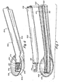
- Fig. 12 illustrates a conventional surgical instrument 1200 having a rongeur-type handle 1202 including a fixed portion 1204 and a moveable portion 1206 connected by a pin connector 1208 and biased by springs 1210 and 1212 configured to keep jaws 1214, positioned at the distal end of the instrument, normally opened.
- Stationary handle portion 1204 is connected to a longitudinally- and distally-extending shaft portion 1216 terminating at its distal end in a foot plate 1218 that may have a rounded, blunt distal-most surface 1220 and includes a cavity 1222 therein (dotted lines).
- Connected to moveable handle portion 1206 is a longitudinally-slideable component 1224.
- Slideable component 1224 is configured to move longitudinally forward in the direction of arrow 1226, when an operator actuates handle 1202 by squeezing. Upon actuation, the distal edge 1228 of slideable component 1224 moves forward (dotted lines) and terminates, when the jaws are completely closed in cavity 1222. Typically, one or both of distal edge 1228 and edges 1230 of cavity 1222 are sharpened so that, upon closing the jaws, slideable component 1224 is able to snip, punch, or otherwise sever tissue in an operating field. For certain typical rongeurs and punches utilized for spine surgery applications, "bite opening" length 1232 is typically on the order of about 16 millimeters. When using device 1200, a surgeon, after snipping or punching a piece of tissue in the surgical operating field, typically must remove the instrument from the operating field at some point to remove tissue from slideable component of 1224 to prevent fouling or clogging of the instrument.
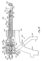
- Liquid-assisted rongeur 1300 comprises one embodiment of a fluid jet-enhanced version of conventional rongeur instrument 1200 shown in Fig. 12 .
- Surgical instrument 1300 can comprise a rongeur-type handle 1202 that can have a fixed portion 1204 and moveable portion 1206 connected by a pin connector 1208 and separated by biasing springs 1210 and 1212, which, in the illustrated embodiment are configured to maintain jaws 1214 in a normally-open configuration.
- a distal extension 1302 of the fixed handle portion 1204 can be configured to support a fixed housing component 1304, which can be affixed thereto.
- Distal extension 1302 can also provide support for a high pressure lumen 1306, which may extend distally from distal extension 1302 to the distal end of the instrument.
- Fixed housing component 1304 can be connected to and support distally extending sheath 1308.
- Distally extending sheath 1308 may include a notch 1310 therein at its distal end defining the "bite opening" of jaws 1214. Distally extending sheath 1308 may also include at its distal most end, distal to notch 1310, an annular ring portion 1312 having a shape configured to mate with, support, and be rigidly attached to a cutting and/or gripping head component 1314, the structure and function of which is explained in more detail below.
- a high pressure hose 220 can connect to fixed handle portion 1204 and to high pressure lumen 1306.
- high-pressure hose 220 may be connected to high pressure lumen 1306 and supported by distal extension 1302 of handle portion 1204 without being directly connected to the handle.
- High pressure lumen 1306 includes a liquid jet-forming nozzle 1318 at its distal end ( Fig. 14 ), which is configured to form a liquid jet 1320 creating an entrainment zone 1321 (dashed lines) directed across notch 1310.
- Cutting/gripping head component 1314 may include a jet passage 1322 therethrough ( Fig. 14 ), which permits liquid jet 1320 to pass through the cutting/gripping head and into notch 1310 during operation.
- Surgical instrument 1300 can further comprise a longitudinally slideable plunger cutting/gripping head 1324 comprising a distal end of longitudinally slideable plunger 1326, which can, optionally, be sharpened to provide a cutting edge.
- plunger 1326 can be hollow along its entire length, thereby providing an evacuation lumen 1328 for removal of tissue and debris from a surgical site, as explained in more detail below.
- the plunger may comprise a solid rod having a hollow portion only near its distal end for forming the distal cutting/gripping head, or may have a proximal end that is plugged to prevent fluid flow through the tube.
- plunger cutting/gripping head 1324 and distal cutting/gripping head component 1314 can be provided with sharpened edges, providing tissue-cutting components, in alternative embodiments, these components may be unsharpened so that the jaws 1214 act not as to punch or cut with sharpened blades, as illustrated, but rather as a clamp, forceps, grabber, or retractor. In certain such embodiments, the liquid jet acts to cut and/or excise the tissue immobilized by the jaws 1214.
- the distal end of plunger 1326 may also include a constriction therein (e.g. similar to necked-down region 804 illustrated in Fig. 8 ) configured to enhance evacuation and/or disaggregation of tissue by the jet during operation.
- Plunger 1326 may be attached to and carried by moveable housing component 1329, which, in turn, may be connected to the moveable handle portion 1206 of handle 1202 via connecting pin 1330.
- hollow plunger 1326 provides an evacuation lumen 1328 and is connected at its proximal end 1332 to an evacuation waste hose 230.
- pulling handle portion 1206 proximally towards fixed handled portion 1204 moves slot 1336 at the top of handle portion 1206 distally, which, in turn, drives pin 1330 distally, thereby moving moveable housing component 1329, plunger 1326, and plunger cutting/gripping head 1324 longitudinally forwardly toward fixed cutting/gripping head component head 1314.
- the particular opening and closing mechanism illustrated may be substituted with a variety of other actuating mechanisms.
- the plunger instead of having plunger 1326 longitudinally movable upon actuation of the handle, in an alternative embodiment, the plunger could remain stationary while distally extending sheath 1308 and cutting/gripping head component 1314 move proximally.
- the plunger 1326 upon actuation of the handle, the plunger 1326 could be configured to move distally while, at the same time, sheath 1308 and cutting/gripping head 1314 move proximally.
- the fully-open space between plunger cutting/gripping head 1324 and the proximal edge 1340 of fixed cutting/gripping head 1314 forms jaws 1214 and defines bite opening length 1232.
- tissue to be cut can be positioned within jaws 1214, and handle 1202 can be actuated by an operator to drive plunger cutting/gripping head 1324 forward in the direction of arrow 1342 and into the tissue (not shown) in notch 1310.
- the diameter of the periphery of edge 1340 of fixed cutting/gripping head 1314 can be selected to be very slightly smaller than the inner diameter of plunger cutting/gripping head 1324.
- plunger cutting/gripping head 1324 Upon bringing plunger cutting/gripping head 1324 together with peripheral edge 1340, when these edges are sharpened to provide cutting blades, a plug of tissue being cut by plunger cutting head 1324 will be severed and contained within the distal end of evacuation lumen 1328, which comprises a conduit-shaped tissue receptacle.
- Plunger cutting/gripping head 1324 and fixed cutting/gripping head 1314 may, preferably, be constructed from durable, hardened, surgically acceptable materials, for example hardened stainless steel, and sized so that a plug of tissue cut by the combination will have a diameter less than that of the minimum inner diameter of any evacuation lumen provided in the instrument.
- the optional shallow cavity 1344 recessed into the proximally-oriented face of fixed cutting head 1314 comprises a flair which can advantageously prevent bone chips from becoming lodged in passage 1322 of the cutting/gripping head during operation.
- a conventional rongeur instrument such as instrument 1200 illustrated in Fig. 12
- inventive surgical instrument 13 00 high pressure liquid, such as isotonic saline, can be supplied to nozzle orifice 1318 to form high pressure liquid jet 1320 during and/or after taking a "bite" of tissue with the instrument.
- Liquid jet 1320 can be positioned to impact tissue excised by the cutting/gripping heads and cut, fragment and/or disaggregate, and flush or push the tissue proximally through evacuation lumen 1328 and away from the surgical site, thereby removing the tissue from the surgical site without the need to remove the entire instrument from the surgical site.
- evacuation lumen 1328 can be connected in fluid communication with a source of external suction, such as a vacuum pump, to bring about or enhance evacuation of fluid and material with the device.
- the liquid jet and evacuation components can be configured, as previously described and as described in commonly-owned U.S. Patent Number 6,375,635 , to enable the force created by the liquid jet to evacuate fluid and debris away from the surgical site without the need for use of an external source of suction.
- the surgeon can first excise a piece of tissue by actuating handle 1202 to drive an (optionally) sharpened plunger cutting/gripping head 1324 distally to excise a plug of tissue. After excising the tissue, the surgeon can then continue to squeeze handle 1202 to maintain the jaw in a closed configuration. Then, while maintaining the jaw in a closed configuration, the surgeon can turn on the liquid jet so that the liquid jet can fragment and/or disaggregate and erode at least a portion of the tissue plug (which would now be inside lumen 1328 of plunger 1326), and/or force the debris proximally through lumen 1328 with the liquid j et.
- the maximum length of the liquid jet during operation i.e. the distance between the outlet of jet nozzle 1318 and the jet-receiving opening 1345 of the plunger cutting/gripping component 1324 comprises a distance 1346 essentially equal to the length of fixed cutting/gripping head 1314.
- this length can be selected to be within the order of a few millimeters (e.g. between 2-5 millimeters).
- the surgeon can first grasp a piece of tissue in jaws 1214 by actuating handle 1202 to drive an unsharpened plunger cutting/gripping head 1324 distally to grasp and immobilize a piece of tissue. After grasping and immobilizing the tissue, the surgeon can then continue to squeeze handle 1202 to maintain the jaw in a closed configuration.
- the surgeon can turn on the liquid jet so that the liquid jet can cut and excise the piece of tissue from the patient and fragment and/or disaggregate and erode at least a portion of the tissue piece, and/or force the tissue debris proximally through lumen 1328 with the liquid jet.
- the surgeon could turn off the jet, allow jaws 1214 to open once again, grab the neat piece of tissue, and repeat the above-described process.
- bite distance 1232 can be as much as about 16 millimeters.
- the jet-forming elements of the instrument can be desirable to configure the jet-forming elements of the instrument to create a highly coherent liquid jet, for example, a jet characterized by a dispersion angle (defined as an apex angle of a cone-shaped region that circumscribes and contains the jet along its length and has an apex at the jet-forming opening of the nozzle and a base defined as the cross-sectional area of the dispersed jet measured in a plane co-planar to the cross-sectional plane through the evacuation lumen at its point of minimum diameter) of between about 3-10 degrees, an in certain embodiments, between about 3-6 degrees
- a dispersion angle defined as an apex angle of a cone-shaped region that circumscribes and contains the jet along its length and has an apex at the jet-forming opening of the nozzle and a base defined as the cross-sectional area of the dispersed jet measured in a plane co-planar to the cross-sectional plane through the evacuation lumen at its point of minimum diameter
- surgical instrument 1300 may utilize many alternative means to activate the tissue-manipulating components at its distal end and may utilize a variety of different types of tissue-manipulating components other than the tissue cutter specifically illustrated.
- surgical instrument 1300 could be configured such that the fluid jet nozzle 1318 is located within the distal end of plunger 1326 and positioned so that the liquid jet emitted therefrom is directed distally toward plunger cutting/gripping head 1324 and fixed cutting/gripping head 1314.
- the liquid jet could be used to fragment and/or disaggregate and erode pieces of tissue from their proximal side rather than their distal side.
- plunger cutting/gripping head 1324 is, optionally, not required to be sharp enough to actually cut tissue, but could rather serve to immobilize tissue being cut by the liquid jet and to contain spray created by the jet.
- the distal end of the device could include a supplemental bone plug crushing, grinding, and/or disaggregating component to reduce the size of bone plugs formed by the instrument before such plugs enter the evacuation lumen.
- a supplemental bone plug crushing, grinding, and/or disaggregating component to reduce the size of bone plugs formed by the instrument before such plugs enter the evacuation lumen.
- One configuration for providing one such bone/tissue grinding element is described below in the context og Figs. 15-17 .
- the grinding element illustrated in Figs. 15-17 could be combined with one or more of the tissue excising components at the distal end of instrument 1300, e.g. liquid jet nozzle 1318.
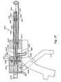
- Figs. 15-17 illustrate other examples of a rongeur-type instrument utilizing a liquid jet to bring about fragmentation and/or disaggregation and/or cutting of tissue within a surgical operating field which are not part of the present invention.
- surgical instrument 1800 illustrated in Figs. 15-17 does not utilize a liquid jet to fragment and/or disaggregate and/or cut tissue by directly impacting tissue with the jet, but rather uses a liquid jet to drive a liquid jet-driven rotor of the instrument, which, in turn, is coupled to a rotatable tissue-contacting component located at the distal end, such that rotation of the liquid jet-driven rotor causes rotation of the rotatable tissue-contacting component.
- the rotatable tissue-contacting component comprises a grinding burr, it should be understood, that in other examples, the rotatable tissue-contacting component could comprise any one of the wide variety of other useful rotating implements.
- Surgical instrument 1800 comprises a liquid jet-driven rotor-powered mechanical cutting tip located at the distal end of the instrument.
- surgical instrument 1800 has the general form of the rongeur or punch.
- the surgical instrument could be configured in the form of a surgical forceps, morcellator, curette, etc.
- a "liquid jet-driven rotor” as used herein refers to a liquid jet-driven motor comprising a jet-driven rotor mechanism utilizing a pressure lumen, having a liquid jet forming nozzle therein, which is configured to direct a liquid jet so that it impacts an impacting surface of a rotor, thus driving rotation of the rotor.
- the term “liquid” does not encompass gases, as this term was previously defined for use in other contexts.
- a liquid jet-driven rotor mechanism as used herein does not utilize an expanding gas or, as is the case with typical prior art liquid-turbines, confine the rotor and liquid flow path within an enclosed duct or channel such that the rotor is essentially completely submerged in a liquid during rotation.
- the liquid driving the rotor undergoes a gradual change in hydrostatic pressure while in contact with the driving surface of the rotor.
- a liquid jet-driven rotor mechanism as used herein maintains the liquid jet-driven rotor within a surrounding gas environment while it is being rotatably driven by a liquid jet during operation.
- liquid jet-driven rotor mechanisms are described in detail in commonly owned U.S. Patent Number 6,511,493 .
- the reader is referred to this patent for a description of particular design parameters and configurations for constructing a liquid jet-driven motor.
- essentially any of the liquid jet-driven rotor mechanisms described in U.S. Patent Number 6,511,493 could potentially be utilized in instruments including such motors.
- one particular configuration that is utilized comprises a liquid jet-driven rotor that is directly attached to a rotating shaft of the instrument carrying the rotatable tissue-contacting component at a distal end thereof such that the rotating shaft and the rotating rotor rotate at the same rotational speed.
- This particular configuration is described in the above-referenced U.S. Patent Number 6,511,493 , and is also described, illustrated, and discussed in commonly owned U.S. Patent Application Publication Number 2003/0083681 A1 .
- instrument 1800 includes a rongeur-type handle 1202, having a fixed portion 1204 and a movable portion 1206 pivotally connected by pin connector 1208 and biased in an open position by springs 1210 and 1212.
- a distal extension portion 1302 of fixed handle portion 1204 is affixed to and supports a fixed housing component 1304, which is attached to and supports distally extending sheath 1308, in a similar fashion as previously described in the context of surgical instrument 1300.
- Distally extending sheath 1308 is connected to and supports at its distal end fixed burr stop component 1802, which serves a somewhat similar function as fixed cutting head 1314 of surgical instrument 1300 previously described.
- fixed burr stop component 1802 serves a somewhat similar function as fixed cutting head 1314 of surgical instrument 1300 previously described.
- a high pressure hose 220 is connected to and supplies high pressure liquid to high pressure lumen 1801 contained within the moveable rotor housing 1812.
- Burr sheath 1814 is connected to and carried by moveable rotor housing component 1812.
- moveable rotor housing component 1812 moves distally and burr sheath 1814 slides longitudinally and distally within distally extending sheath 1308.
- Burr 1804 is supported within burr sheath 1814 by distal bearing 1816 and proximal bearing 1818.
- Burr sheath 1814 is attached to and carried by a moveable rotor housing 1812, which is connected to moveable handle portion 1206 via slot 1336 and pin 1330.
- the waste hose 1820 is connected to the proximal end of burr sheath 1814 via tubing connector 1822.
- Burr 1804 is connected to the distal end of a burr shaft 1824, which is rigidly attached to liquid jet-driven rotor 1826 located within rotor chamber 1828 of moveable rotor housing 1812.
- Liquid jet-driven rotor 1826 is driven in rotation via impact with a liquid jet emitted from nozzle 1830 in high pressure lumen 1801.
- the nozzle is configured to produced a highly collimated liquid jet. Because liquid jet-driven rotor 1826 is directly connected to burr shaft 1824, burr 1804 will rotate at the same speed as rotor 1826, when the instrument is in operation.
- tissue or bone to be cut or abated is introduced into jaw 1214 and handle 1202 is squeezed, which advances moveable rotor housing 1812 distally, and with it burr sheath 1814, burr shaft 1824, and burr 1804.
- burr sheath 1814 slides through distally extending sheath 1308, so that burr 1804 enters into notch 1310.
- Pressurized fluid is directed through high pressure lumen 1801 to nozzle 1830 to create a liquid jet directed to impact jet-impacting surfaces 1831 on liquid jet-driven rotor 1826.
- the high pressure liquid jet can accelerate and drive burr 1804 in rapid rotation, for example in the range of about 10,000 RPM to over 50,000 RPM under no-load conditions. Further squeezing of handle 1202 forces the rotating burr 1804 into contact with tissue within notch 1310 of jaw 1214, thereby grinding and disaggregating the tissue.
- burr sheath 1814 may extend distally to a greater extent than illustrated, such that its distal-most portion is distal to or at the same location as the distal most end of burr 1804.
- the distal end of burr sheath 1814 could be sharpened to provide a cutting blade/punch similar to plunger cutting head 1324 of instrument 1300 illustrated in Figs. 13 and 14 and described previously.
- the distal cutting edge of burr sheath 1814 could be utilized to cut target tissue which could then be disaggregated by the action of burr 1804.
- a sheath may be provided so that as the burr is moved out of the sheath 1308, the burr sheath 1814 is also extended such that it surrounds the burr and protects contiguous tissue from adventitious contact with the burr 1804 or its shaft 1824.
- Moveable rotor housing component 1812 may include a liquid bypass line 1832 therein, as illustrated, which can enable liquid evacuated from rotor chamber 1828 to bypass proximal bearing 1818.
- liquid and tissue debris can be evacuated from the distal end of the instrument via passage through a lumen 1835 centrally located along the length of hollow burr shaft 1824, which is fluid communication with suction tube 1820 (see arrows 1834).
- a suction inlet 1836 is provided near the distal end of burr shaft 1824 to enable liquid entry into lumen 1835 in shaft 1824.
- the evacuation opening 1836 can be scooped-shaped and configured so that inlet opening 1836 faces the direction of the burr shaft rotation when in operation. Such a configuration allows for the rotational energy of the burr to assist in or facilitate evacuation of liquid and debris proximally through the lumen 1835 of the hollow burr shaft 1824.
- Hollow shafted burrs are commercially available (e.g. from Smith & Nephew Dionics) and are described in greater detail in U.S. Patent Number 6,511,493 .
- FIG. 17 Illustrated in Fig. 17 , in cross section, is an alternative example for configuring the evacuation system of liquid jet-driven rotating burr rongeur instrument 1800.
- rotating burr shaft 2002 is solid and does not include an evacuation lumen therein. Rather, liquid and tissue debris at the distal end of the instrument is evacuated through the annular space 2004 surrounding burr shaft 2002 and within burr sheath 2006 (see arrows 2007).
- Burr sheath 2006 is sealed in its proximal end 2008 and includes, such as at a location proximal to moveable rotor housing component 2010, a suction hose connector 2012, which is in fluid communication with annular space 2004.
- tissue and debris can be evacuated from the distal end of burr sheath 2006 through annular inlet opening 2014, through burr shafts spacer element 2016 via passage ways 2018 therein, through annular lumen 2004, and into suction tube 1820 via connector 2012.
- bearing support for burr shaft 2002 is provided by two proximally-located bearings 2020.
- Distally located spacer 2016 serves only to prevent burr shaft 2002 from contacting the inner surface of burr sheath 2006 upon lateral deflection, but, in certain embodiments, does not provide any substantial bearing support during normal operation. In fact, in certain examples, distal spacer 2016 can be eliminated entirely.
- a detailed description of various configurations and design considerations for constructing liquid jet-driven burr instruments having only proximally-located bearing support, such as in the configuration illustrated in Fig. 17 is provided in commonly owned U.S. Patent Application Number 2003/0083681 A1 , to which the reader is referred for more detail.
- liquid jet rotor housing chamber 2024 is evacuated, so as to remove liquid comprising the liquid jet utilized to drive the rotor in order to maintain the housing free of liquid build-up during operation, via evacuation line 2026, which is fluid communication with suction tube 1820 and enters rotor chamber 2024 at its bottom-most portion 2028.
- evacuation line 2026 which is fluid communication with suction tube 1820 and enters rotor chamber 2024 at its bottom-most portion 2028.
- kits including one or more of the surgical instruments disclosed herein, or components thereof, together with instructions for use directed to an operator of the instruments.
- Instructions typically involve written instructions on or associated with packaging of instruments, or components thereof, of the invention. Instructions also can include any oral or electronic instructions provided in any manner.
- kits typically define a package including both any one or a combination of one or more surgical instruments, or components thereof, of the invention and the instructions, but can also include a surgical instrument of the invention, or component thereof, and instructions of any form that are provided in connection with the instrument in any manner such that a professional operator of the instrument will clearly recognize that the instructions are to be associated with the specific instrument.
- kits comprises a surgical instrument of the invention, or a component thereof, in combination with instructions directing an operator to dispose of at least a portion of the instrument after a single use.
- the instructions direct the operator to dispose of only a portion of the instrument after a single use and to reuse the remainder of the instrument.
- the instructions further direct an operator to dispose of one or more of the pressure lumen, evacuation lumen, nozzle, or non-liquid jet tissue-cutting component (e.g. cutting blade, burr, etc.) of the instrument, while retaining the remainder of the instrument for re-use.
- the kits provide instructions directing an operator to dispose of the entire instrument after a single use.
Claims (17)
- Instrument chirurgical ayant une extrémité proximale qui comprend une poignée et une extrémité distale qui est située en face de l'extrémité proximale dans une direction axiale, l'instrument comprenant :une embouchure (208, 614, 1318) située au niveau de l'extrémité distale de l'instrument qui est formée pour obtenir un jet de liquide (210, 1320) ;une lumière de pression (214, 604, 1306) configurée et positionnée pour acheminer un écoulement de liquide vers l'embouchure ;une lumière d'évacuation (228, 602, 1328) comprenant une ouverture de réception de jet (226, 616) située en face de l'embouchure pour recevoir au moins une partie du jet de liquide émis de l'embouchure, lorsque l'instrument opère, et qui est configurée et positionnée pour acheminer un écoulement de liquide loin de l'ouverture de réception de jet ; etun composant de grattage ou de découpage de tissu (206, 608, 803, 1314) situé au niveau de l'extrémité distale du dispositif et construit et positionné pour exciser un tissu durant la procédure chirurgicale par grattage ou découpage,caractérisé en ce que, durant l'opération de l'instrument, le jet de liquide est orienté depuis l'embouchure vers essentiellement l'extrémité proximale de l'instrument dans la direction axiale.
- Instrument chirurgical de la revendication 1, comprenant en plues :un réceptacle de tissu (114) configuré et positionné pour contenir le tissu excisé par le composant de grattage ou de découpage de tissu, où l'embouchure est positionnée, durant l'opération de l'instrument, pour orienter le jet de liquide de sorte qu'une partie au moins du jet de liquide soit contenue dans le réceptacle.
- Instrument chirurgical de la revendication 2, dans lequel le réceptacle de tissu est en forme de coupelle.
- Instrument chirurgical de la revendication 2 ou 3, dans lequel au moins une partie d'un bord (108) du réceptacle est suffisamment acérée pour former une lame de découpage de tissu du composant de grattage ou de découpage de tissu.
- Instrument chirurgical de l'une des revendications précédentes, dans lequel la lumière de pression est configurée pour être apte à acheminer un liquide haute pression à une pression d'au moins 6,9 MPa (1,000 psig).
- Instrument chirurgical de la revendication 5, dans lequel la lumière de pression est configurée pour être apte à acheminer un liquide haute pression à une pression d'au moins 34,5 MPa (5,000 psig).
- Instrument chirurgical de l'une des revendications précédentes, dans lequel la lumière d'évacuation est formée et positionnée pour être apte à retirer d'un site chirurgical au moins une partie de tissu excisé par le composant de grattage ou de découpage de tissu durant une opération.
- Instrument chirurgical de l'une des revendications précédentes, dans lequel la lumière d'évacuation est formée et positionnable pour permettre une évacuation d'essentiellement la totalité du liquide comprenant le jet de liquide de l'ouverture de réception de jet à une extrémité proximale de l'instrument, sans recours à une source externe d'aspiration.
- Instrument chirurgical de l'une des revendications précédentes, dans lequel la lumière d'évacuation comporte une expansion de diamètre interne à un point définissant l'emplacement de l'entrée de l'ouverture de réception de jet ou à un point en aval correspondant pour améliorer l'aspiration au niveau de l'ouverture de réception de jet.
- Instrument chirurgical de la revendication 9, dans lequel la lumière d'évacuation comporte une région de diamètre interne réduit située en aval de l'ouverture de réception de jet et une expansion du diamètre interne adjacent à ladite région de diamètre interne réduit et en aval de celle-ci.
- Instrument chirurgical de la revendication 1, dans lequel le composant de grattage ou de découpage de tissu comprend un découpeur mécanique (1324).
- Instrument chirurgical de la revendication 11, dans lequel le découpeur mécanique comprend une lame aiguisée.
- Instrument chirurgical de la revendication 1, dans lequel une distance séparant l'ouverture de réception de jet de la lumière d'évacuation de l'embouchure définit une longueur du jet de liquide émis de l'embouchure, et où la distance séparant l'ouverture de réception de jet de la lumière d'évacuation de l'embouchure est réglable par un opérateur de l'instrument.
- Instrument chirurgical de la revendication 1, comprenant en plues :une extrémité distale (206, 608, 800, 1300) adaptée pour effectuer une procédure chirurgicale sur un patient,où l'embouchure est configurée de sorte que le jet de liquide soit émis par l'embouchure et orienté pour entrer en contact avec le tissu excisé par le composant de grattage ou de découpage de tissu afin que le jet de liquide émis par l'embouchure soit apte à découper au moins une partie du tissu excisé et/ou entraîner au moins une partie du tissu excisé dans la lumière d'évacuation et au moins partiellement à travers celle-ci.
- Instrument chirurgical de la revendication 1, comprenant en plues :une extrémité distale adaptée pour effectuer une procédure chirurgicale sur un patient,où l'extrémité distale de l'instrument chirurgical a une forme et une taille sélectionnées pour faciliter l'insertion de l'extrémité distale dans une région du corps du patient définissant un site chirurgical, où la région du corps du patient définissant un site chirurgical est la colonne vertébrale du patient.
- Instrument chirurgical de la revendication 1, dans lequel l'instrument chirurgical comprend un dispositif sélectionné du groupe constitué d'une curette, d'une pince-gouge, d'une pince emporte-pièce, d'une pince à esquille, d'un système de morcellement, et d'un dispositif de préhension chirurgical.
- Instrument chirurgical de l'une des revendications précédentes, dans lequel le composant de grattage ou de découpage de tissu est essentiellement en face de l'ouverture de réception de jet et s'étend radialement vers l'extérieur d'un emplacement défini par un centre axial de l'embouchure à une périphérie radiale ayant un bord aiguisé.
Applications Claiming Priority (5)
| Application Number | Priority Date | Filing Date | Title |
|---|---|---|---|
| US42121902P | 2002-10-25 | 2002-10-25 | |
| US421219P | 2002-10-25 | ||
| US48802403P | 2003-07-17 | 2003-07-17 | |
| US488024P | 2003-07-17 | ||
| PCT/US2003/034174 WO2004037095A2 (fr) | 2002-10-25 | 2003-10-27 | Dispositifs chirurgicaux permettant une manipulation des tissus assistee par jet liquide et procedes d'utilisation |
Publications (2)
| Publication Number | Publication Date |
|---|---|
| EP1558152A2 EP1558152A2 (fr) | 2005-08-03 |
| EP1558152B1 true EP1558152B1 (fr) | 2010-10-27 |
Family
ID=32179844
Family Applications (1)
| Application Number | Title | Priority Date | Filing Date |
|---|---|---|---|
| EP03809652A Expired - Lifetime EP1558152B1 (fr) | 2002-10-25 | 2003-10-27 | Dispositifs chirurgicaux permettant une manipulation des tissus assistee par jet liquide |
Country Status (7)
| Country | Link |
|---|---|
| EP (1) | EP1558152B1 (fr) |
| JP (1) | JP2006503682A (fr) |
| AT (1) | ATE485777T1 (fr) |
| AU (1) | AU2003301525A1 (fr) |
| CA (1) | CA2502984A1 (fr) |
| DE (1) | DE60334720D1 (fr) |
| WO (1) | WO2004037095A2 (fr) |
Families Citing this family (146)
| Publication number | Priority date | Publication date | Assignee | Title |
|---|---|---|---|---|
| US7011644B1 (en) | 1995-02-06 | 2006-03-14 | Andrew Mark S | Tissue liquefaction and aspiration for dental treatment |
| US11229472B2 (en) | 2001-06-12 | 2022-01-25 | Cilag Gmbh International | Modular battery powered handheld surgical instrument with multiple magnetic position sensors |
| US8162966B2 (en) | 2002-10-25 | 2012-04-24 | Hydrocision, Inc. | Surgical devices incorporating liquid jet assisted tissue manipulation and methods for their use |
| US10363061B2 (en) | 2002-10-25 | 2019-07-30 | Hydrocision, Inc. | Nozzle assemblies for liquid jet surgical instruments and surgical instruments for employing the nozzle assemblies |
| US8182501B2 (en) | 2004-02-27 | 2012-05-22 | Ethicon Endo-Surgery, Inc. | Ultrasonic surgical shears and method for sealing a blood vessel using same |
| DE202004014104U1 (de) * | 2004-09-08 | 2004-12-16 | Human Med Ag | Chirurgische Einrichtung zur Entnahme von Gewebezellen aus einer biologischen Struktur |
| US20060079877A1 (en) | 2004-10-08 | 2006-04-13 | Houser Kevin L | Feedback mechanism for use with an ultrasonic surgical instrument |
| US20070191713A1 (en) | 2005-10-14 | 2007-08-16 | Eichmann Stephen E | Ultrasonic device for cutting and coagulating |
| US7621930B2 (en) | 2006-01-20 | 2009-11-24 | Ethicon Endo-Surgery, Inc. | Ultrasound medical instrument having a medical ultrasonic blade |
| CA2642373C (fr) * | 2006-02-27 | 2014-06-03 | Feather Safety Razor Co., Ltd. | Outil a arete |
| US8911460B2 (en) | 2007-03-22 | 2014-12-16 | Ethicon Endo-Surgery, Inc. | Ultrasonic surgical instruments |
| US20080234709A1 (en) | 2007-03-22 | 2008-09-25 | Houser Kevin L | Ultrasonic surgical instrument and cartilage and bone shaping blades therefor |
| US8057498B2 (en) | 2007-11-30 | 2011-11-15 | Ethicon Endo-Surgery, Inc. | Ultrasonic surgical instrument blades |
| US8142461B2 (en) | 2007-03-22 | 2012-03-27 | Ethicon Endo-Surgery, Inc. | Surgical instruments |
| US8226675B2 (en) | 2007-03-22 | 2012-07-24 | Ethicon Endo-Surgery, Inc. | Surgical instruments |
| BRPI0811017A2 (pt) | 2007-04-30 | 2015-01-27 | Andrew Technologies Llc | Lipoaspiração baseada na liquefação de tecido. |
| US9271751B2 (en) * | 2007-05-29 | 2016-03-01 | Ethicon Endo-Surgery, Llc | Ultrasonic surgical system |
| DE202007008972U1 (de) | 2007-06-27 | 2008-11-06 | Human Med Ag | Vorrichtung zur chirurgischen Behandlung biologischer Strukturen |
| US8523889B2 (en) | 2007-07-27 | 2013-09-03 | Ethicon Endo-Surgery, Inc. | Ultrasonic end effectors with increased active length |
| US8882791B2 (en) | 2007-07-27 | 2014-11-11 | Ethicon Endo-Surgery, Inc. | Ultrasonic surgical instruments |
| US8808319B2 (en) | 2007-07-27 | 2014-08-19 | Ethicon Endo-Surgery, Inc. | Surgical instruments |
| US8430898B2 (en) | 2007-07-31 | 2013-04-30 | Ethicon Endo-Surgery, Inc. | Ultrasonic surgical instruments |
| US8252012B2 (en) | 2007-07-31 | 2012-08-28 | Ethicon Endo-Surgery, Inc. | Ultrasonic surgical instrument with modulator |
| US9044261B2 (en) | 2007-07-31 | 2015-06-02 | Ethicon Endo-Surgery, Inc. | Temperature controlled ultrasonic surgical instruments |
| US8512365B2 (en) | 2007-07-31 | 2013-08-20 | Ethicon Endo-Surgery, Inc. | Surgical instruments |
| CN101883531B (zh) | 2007-10-05 | 2014-07-02 | 伊西康内外科公司 | 人体工程学外科手术器械 |
| US10010339B2 (en) | 2007-11-30 | 2018-07-03 | Ethicon Llc | Ultrasonic surgical blades |
| US9089360B2 (en) | 2008-08-06 | 2015-07-28 | Ethicon Endo-Surgery, Inc. | Devices and techniques for cutting and coagulating tissue |
| US8058771B2 (en) | 2008-08-06 | 2011-11-15 | Ethicon Endo-Surgery, Inc. | Ultrasonic device for cutting and coagulating with stepped output |
| US9700339B2 (en) | 2009-05-20 | 2017-07-11 | Ethicon Endo-Surgery, Inc. | Coupling arrangements and methods for attaching tools to ultrasonic surgical instruments |
| US8650728B2 (en) | 2009-06-24 | 2014-02-18 | Ethicon Endo-Surgery, Inc. | Method of assembling a transducer for a surgical instrument |
| US8461744B2 (en) | 2009-07-15 | 2013-06-11 | Ethicon Endo-Surgery, Inc. | Rotating transducer mount for ultrasonic surgical instruments |
| US9017326B2 (en) | 2009-07-15 | 2015-04-28 | Ethicon Endo-Surgery, Inc. | Impedance monitoring apparatus, system, and method for ultrasonic surgical instruments |
| US8663220B2 (en) | 2009-07-15 | 2014-03-04 | Ethicon Endo-Surgery, Inc. | Ultrasonic surgical instruments |
| US10441345B2 (en) | 2009-10-09 | 2019-10-15 | Ethicon Llc | Surgical generator for ultrasonic and electrosurgical devices |
| US11090104B2 (en) | 2009-10-09 | 2021-08-17 | Cilag Gmbh International | Surgical generator for ultrasonic and electrosurgical devices |
| US8986302B2 (en) | 2009-10-09 | 2015-03-24 | Ethicon Endo-Surgery, Inc. | Surgical generator for ultrasonic and electrosurgical devices |
| US9168054B2 (en) | 2009-10-09 | 2015-10-27 | Ethicon Endo-Surgery, Inc. | Surgical generator for ultrasonic and electrosurgical devices |
| USRE47996E1 (en) | 2009-10-09 | 2020-05-19 | Ethicon Llc | Surgical generator for ultrasonic and electrosurgical devices |
| US8591459B2 (en) * | 2009-12-21 | 2013-11-26 | Ethicon Endo-Surgery, Inc. | Use of biomarkers and therapeutic agents with surgical devices |
| US8986334B2 (en) * | 2010-02-04 | 2015-03-24 | Nico Corporation | Tissue removal device with tissue grip |
| US8951272B2 (en) | 2010-02-11 | 2015-02-10 | Ethicon Endo-Surgery, Inc. | Seal arrangements for ultrasonically powered surgical instruments |
| US8531064B2 (en) | 2010-02-11 | 2013-09-10 | Ethicon Endo-Surgery, Inc. | Ultrasonically powered surgical instruments with rotating cutting implement |
| US9259234B2 (en) | 2010-02-11 | 2016-02-16 | Ethicon Endo-Surgery, Llc | Ultrasonic surgical instruments with rotatable blade and hollow sheath arrangements |
| US8419759B2 (en) * | 2010-02-11 | 2013-04-16 | Ethicon Endo-Surgery, Inc. | Ultrasonic surgical instrument with comb-like tissue trimming device |
| US8961547B2 (en) | 2010-02-11 | 2015-02-24 | Ethicon Endo-Surgery, Inc. | Ultrasonic surgical instruments with moving cutting implement |
| US8486096B2 (en) | 2010-02-11 | 2013-07-16 | Ethicon Endo-Surgery, Inc. | Dual purpose surgical instrument for cutting and coagulating tissue |
| US8469981B2 (en) | 2010-02-11 | 2013-06-25 | Ethicon Endo-Surgery, Inc. | Rotatable cutting implement arrangements for ultrasonic surgical instruments |
| US8579928B2 (en) | 2010-02-11 | 2013-11-12 | Ethicon Endo-Surgery, Inc. | Outer sheath and blade arrangements for ultrasonic surgical instruments |
| GB2480498A (en) | 2010-05-21 | 2011-11-23 | Ethicon Endo Surgery Inc | Medical device comprising RF circuitry |
| US8795327B2 (en) | 2010-07-22 | 2014-08-05 | Ethicon Endo-Surgery, Inc. | Electrosurgical instrument with separate closure and cutting members |
| US9192431B2 (en) | 2010-07-23 | 2015-11-24 | Ethicon Endo-Surgery, Inc. | Electrosurgical cutting and sealing instrument |
| US9259265B2 (en) | 2011-07-22 | 2016-02-16 | Ethicon Endo-Surgery, Llc | Surgical instruments for tensioning tissue |
| WO2013119545A1 (fr) | 2012-02-10 | 2013-08-15 | Ethicon-Endo Surgery, Inc. | Instrument chirurgical robotisé |
| US9237921B2 (en) | 2012-04-09 | 2016-01-19 | Ethicon Endo-Surgery, Inc. | Devices and techniques for cutting and coagulating tissue |
| US9724118B2 (en) | 2012-04-09 | 2017-08-08 | Ethicon Endo-Surgery, Llc | Techniques for cutting and coagulating tissue for ultrasonic surgical instruments |
| US9241731B2 (en) | 2012-04-09 | 2016-01-26 | Ethicon Endo-Surgery, Inc. | Rotatable electrical connection for ultrasonic surgical instruments |
| US9226766B2 (en) | 2012-04-09 | 2016-01-05 | Ethicon Endo-Surgery, Inc. | Serial communication protocol for medical device |
| US9439668B2 (en) | 2012-04-09 | 2016-09-13 | Ethicon Endo-Surgery, Llc | Switch arrangements for ultrasonic surgical instruments |
| DE102012103153A1 (de) | 2012-04-12 | 2013-10-17 | Karl Storz Gmbh & Co. Kg | Medizinisches Instrument zum Abtrennen von Gewebe und Knorpel |
| US20140005705A1 (en) | 2012-06-29 | 2014-01-02 | Ethicon Endo-Surgery, Inc. | Surgical instruments with articulating shafts |
| US9226767B2 (en) | 2012-06-29 | 2016-01-05 | Ethicon Endo-Surgery, Inc. | Closed feedback control for electrosurgical device |
| US9820768B2 (en) | 2012-06-29 | 2017-11-21 | Ethicon Llc | Ultrasonic surgical instruments with control mechanisms |
| US9408622B2 (en) | 2012-06-29 | 2016-08-09 | Ethicon Endo-Surgery, Llc | Surgical instruments with articulating shafts |
| US9283045B2 (en) | 2012-06-29 | 2016-03-15 | Ethicon Endo-Surgery, Llc | Surgical instruments with fluid management system |
| US9198714B2 (en) | 2012-06-29 | 2015-12-01 | Ethicon Endo-Surgery, Inc. | Haptic feedback devices for surgical robot |
| US20140005702A1 (en) | 2012-06-29 | 2014-01-02 | Ethicon Endo-Surgery, Inc. | Ultrasonic surgical instruments with distally positioned transducers |
| US9351754B2 (en) | 2012-06-29 | 2016-05-31 | Ethicon Endo-Surgery, Llc | Ultrasonic surgical instruments with distally positioned jaw assemblies |
| US9393037B2 (en) | 2012-06-29 | 2016-07-19 | Ethicon Endo-Surgery, Llc | Surgical instruments with articulating shafts |
| US9326788B2 (en) | 2012-06-29 | 2016-05-03 | Ethicon Endo-Surgery, Llc | Lockout mechanism for use with robotic electrosurgical device |
| EP2900158B1 (fr) | 2012-09-28 | 2020-04-15 | Ethicon LLC | Pince bipolaire multifonction |
| US10201365B2 (en) | 2012-10-22 | 2019-02-12 | Ethicon Llc | Surgeon feedback sensing and display methods |
| US9095367B2 (en) | 2012-10-22 | 2015-08-04 | Ethicon Endo-Surgery, Inc. | Flexible harmonic waveguides/blades for surgical instruments |
| US20140135804A1 (en) | 2012-11-15 | 2014-05-15 | Ethicon Endo-Surgery, Inc. | Ultrasonic and electrosurgical devices |
| US10226273B2 (en) | 2013-03-14 | 2019-03-12 | Ethicon Llc | Mechanical fasteners for use with surgical energy devices |
| US9241728B2 (en) | 2013-03-15 | 2016-01-26 | Ethicon Endo-Surgery, Inc. | Surgical instrument with multiple clamping mechanisms |
| US10987463B2 (en) | 2013-09-06 | 2021-04-27 | Medaxis Ag | Handpiece for cleaning wounds |
| US9814514B2 (en) | 2013-09-13 | 2017-11-14 | Ethicon Llc | Electrosurgical (RF) medical instruments for cutting and coagulating tissue |
| US9265926B2 (en) | 2013-11-08 | 2016-02-23 | Ethicon Endo-Surgery, Llc | Electrosurgical devices |
| GB2521228A (en) | 2013-12-16 | 2015-06-17 | Ethicon Endo Surgery Inc | Medical device |
| GB2521229A (en) | 2013-12-16 | 2015-06-17 | Ethicon Endo Surgery Inc | Medical device |
| US9795436B2 (en) | 2014-01-07 | 2017-10-24 | Ethicon Llc | Harvesting energy from a surgical generator |
| AT14607U1 (de) * | 2014-02-13 | 2016-02-15 | Bhdt Gmbh | Absorber für eine in der Osteotomie verwendete Wasserstrahl-Schneideinrichtung |
| US9554854B2 (en) | 2014-03-18 | 2017-01-31 | Ethicon Endo-Surgery, Llc | Detecting short circuits in electrosurgical medical devices |
| US10463421B2 (en) | 2014-03-27 | 2019-11-05 | Ethicon Llc | Two stage trigger, clamp and cut bipolar vessel sealer |
| US10092310B2 (en) | 2014-03-27 | 2018-10-09 | Ethicon Llc | Electrosurgical devices |
| US9737355B2 (en) | 2014-03-31 | 2017-08-22 | Ethicon Llc | Controlling impedance rise in electrosurgical medical devices |
| US9913680B2 (en) | 2014-04-15 | 2018-03-13 | Ethicon Llc | Software algorithms for electrosurgical instruments |
| WO2015171754A1 (fr) * | 2014-05-07 | 2015-11-12 | Massachusetts Institute Of Technology | Appareil de débridement utilisant des moteurs linéaires à force de lorentz |
| US10285724B2 (en) | 2014-07-31 | 2019-05-14 | Ethicon Llc | Actuation mechanisms and load adjustment assemblies for surgical instruments |
| US10639092B2 (en) | 2014-12-08 | 2020-05-05 | Ethicon Llc | Electrode configurations for surgical instruments |
| US10245095B2 (en) | 2015-02-06 | 2019-04-02 | Ethicon Llc | Electrosurgical instrument with rotation and articulation mechanisms |
| US10321950B2 (en) | 2015-03-17 | 2019-06-18 | Ethicon Llc | Managing tissue treatment |
| US10342602B2 (en) | 2015-03-17 | 2019-07-09 | Ethicon Llc | Managing tissue treatment |
| US10595929B2 (en) | 2015-03-24 | 2020-03-24 | Ethicon Llc | Surgical instruments with firing system overload protection mechanisms |
| US10034684B2 (en) | 2015-06-15 | 2018-07-31 | Ethicon Llc | Apparatus and method for dissecting and coagulating tissue |
| US11020140B2 (en) | 2015-06-17 | 2021-06-01 | Cilag Gmbh International | Ultrasonic surgical blade for use with ultrasonic surgical instruments |
| US10034704B2 (en) | 2015-06-30 | 2018-07-31 | Ethicon Llc | Surgical instrument with user adaptable algorithms |
| US11051873B2 (en) | 2015-06-30 | 2021-07-06 | Cilag Gmbh International | Surgical system with user adaptable techniques employing multiple energy modalities based on tissue parameters |
| US11129669B2 (en) | 2015-06-30 | 2021-09-28 | Cilag Gmbh International | Surgical system with user adaptable techniques based on tissue type |
| US10898256B2 (en) | 2015-06-30 | 2021-01-26 | Ethicon Llc | Surgical system with user adaptable techniques based on tissue impedance |
| US11141213B2 (en) | 2015-06-30 | 2021-10-12 | Cilag Gmbh International | Surgical instrument with user adaptable techniques |
| US10357303B2 (en) | 2015-06-30 | 2019-07-23 | Ethicon Llc | Translatable outer tube for sealing using shielded lap chole dissector |
| US10154852B2 (en) | 2015-07-01 | 2018-12-18 | Ethicon Llc | Ultrasonic surgical blade with improved cutting and coagulation features |
| US11058475B2 (en) | 2015-09-30 | 2021-07-13 | Cilag Gmbh International | Method and apparatus for selecting operations of a surgical instrument based on user intention |
| US10595930B2 (en) | 2015-10-16 | 2020-03-24 | Ethicon Llc | Electrode wiping surgical device |
| US10179022B2 (en) | 2015-12-30 | 2019-01-15 | Ethicon Llc | Jaw position impedance limiter for electrosurgical instrument |
| US10575892B2 (en) | 2015-12-31 | 2020-03-03 | Ethicon Llc | Adapter for electrical surgical instruments |
| US10537351B2 (en) | 2016-01-15 | 2020-01-21 | Ethicon Llc | Modular battery powered handheld surgical instrument with variable motor control limits |
| US11129670B2 (en) | 2016-01-15 | 2021-09-28 | Cilag Gmbh International | Modular battery powered handheld surgical instrument with selective application of energy based on button displacement, intensity, or local tissue characterization |
| US10716615B2 (en) | 2016-01-15 | 2020-07-21 | Ethicon Llc | Modular battery powered handheld surgical instrument with curved end effectors having asymmetric engagement between jaw and blade |
| US11229471B2 (en) | 2016-01-15 | 2022-01-25 | Cilag Gmbh International | Modular battery powered handheld surgical instrument with selective application of energy based on tissue characterization |
| US10555769B2 (en) | 2016-02-22 | 2020-02-11 | Ethicon Llc | Flexible circuits for electrosurgical instrument |
| US10646269B2 (en) | 2016-04-29 | 2020-05-12 | Ethicon Llc | Non-linear jaw gap for electrosurgical instruments |
| US10485607B2 (en) | 2016-04-29 | 2019-11-26 | Ethicon Llc | Jaw structure with distal closure for electrosurgical instruments |
| US10702329B2 (en) | 2016-04-29 | 2020-07-07 | Ethicon Llc | Jaw structure with distal post for electrosurgical instruments |
| US10456193B2 (en) | 2016-05-03 | 2019-10-29 | Ethicon Llc | Medical device with a bilateral jaw configuration for nerve stimulation |
| US10245064B2 (en) | 2016-07-12 | 2019-04-02 | Ethicon Llc | Ultrasonic surgical instrument with piezoelectric central lumen transducer |
| US10893883B2 (en) | 2016-07-13 | 2021-01-19 | Ethicon Llc | Ultrasonic assembly for use with ultrasonic surgical instruments |
| US10842522B2 (en) | 2016-07-15 | 2020-11-24 | Ethicon Llc | Ultrasonic surgical instruments having offset blades |
| CN106017976A (zh) * | 2016-07-25 | 2016-10-12 | 石红 | 一种临床病理诊断用的病理标本切割刀 |
| US10376305B2 (en) | 2016-08-05 | 2019-08-13 | Ethicon Llc | Methods and systems for advanced harmonic energy |
| US10285723B2 (en) | 2016-08-09 | 2019-05-14 | Ethicon Llc | Ultrasonic surgical blade with improved heel portion |
| USD847990S1 (en) | 2016-08-16 | 2019-05-07 | Ethicon Llc | Surgical instrument |
| US10828056B2 (en) | 2016-08-25 | 2020-11-10 | Ethicon Llc | Ultrasonic transducer to waveguide acoustic coupling, connections, and configurations |
| US10952759B2 (en) | 2016-08-25 | 2021-03-23 | Ethicon Llc | Tissue loading of a surgical instrument |
| US10603064B2 (en) | 2016-11-28 | 2020-03-31 | Ethicon Llc | Ultrasonic transducer |
| US11266430B2 (en) | 2016-11-29 | 2022-03-08 | Cilag Gmbh International | End effector control and calibration |
| US10820920B2 (en) | 2017-07-05 | 2020-11-03 | Ethicon Llc | Reusable ultrasonic medical devices and methods of their use |
| WO2019032716A1 (fr) * | 2017-08-09 | 2019-02-14 | Boston Scientific Scimed, Inc. | Système d'endoscopie et procédés associés |
| US11786294B2 (en) | 2019-12-30 | 2023-10-17 | Cilag Gmbh International | Control program for modular combination energy device |
| US11779387B2 (en) | 2019-12-30 | 2023-10-10 | Cilag Gmbh International | Clamp arm jaw to minimize tissue sticking and improve tissue control |
| US11944366B2 (en) | 2019-12-30 | 2024-04-02 | Cilag Gmbh International | Asymmetric segmented ultrasonic support pad for cooperative engagement with a movable RF electrode |
| US20210196357A1 (en) | 2019-12-30 | 2021-07-01 | Ethicon Llc | Electrosurgical instrument with asynchronous energizing electrodes |
| US11812957B2 (en) | 2019-12-30 | 2023-11-14 | Cilag Gmbh International | Surgical instrument comprising a signal interference resolution system |
| US11684412B2 (en) | 2019-12-30 | 2023-06-27 | Cilag Gmbh International | Surgical instrument with rotatable and articulatable surgical end effector |
| US11779329B2 (en) | 2019-12-30 | 2023-10-10 | Cilag Gmbh International | Surgical instrument comprising a flex circuit including a sensor system |
| US20210196359A1 (en) | 2019-12-30 | 2021-07-01 | Ethicon Llc | Electrosurgical instruments with electrodes having energy focusing features |
| US11911063B2 (en) | 2019-12-30 | 2024-02-27 | Cilag Gmbh International | Techniques for detecting ultrasonic blade to electrode contact and reducing power to ultrasonic blade |
| US11696776B2 (en) | 2019-12-30 | 2023-07-11 | Cilag Gmbh International | Articulatable surgical instrument |
| US11937866B2 (en) | 2019-12-30 | 2024-03-26 | Cilag Gmbh International | Method for an electrosurgical procedure |
| US11937863B2 (en) | 2019-12-30 | 2024-03-26 | Cilag Gmbh International | Deflectable electrode with variable compression bias along the length of the deflectable electrode |
| US11452525B2 (en) | 2019-12-30 | 2022-09-27 | Cilag Gmbh International | Surgical instrument comprising an adjustment system |
| US11786291B2 (en) | 2019-12-30 | 2023-10-17 | Cilag Gmbh International | Deflectable support of RF energy electrode with respect to opposing ultrasonic blade |
| US11950797B2 (en) | 2019-12-30 | 2024-04-09 | Cilag Gmbh International | Deflectable electrode with higher distal bias relative to proximal bias |
| US11660089B2 (en) | 2019-12-30 | 2023-05-30 | Cilag Gmbh International | Surgical instrument comprising a sensing system |
Family Cites Families (8)
| Publication number | Priority date | Publication date | Assignee | Title |
|---|---|---|---|---|
| US3565062A (en) * | 1968-06-13 | 1971-02-23 | Ultrasonic Systems | Ultrasonic method and apparatus for removing cholesterol and other deposits from blood vessels and the like |
| DE8426270U1 (de) * | 1984-09-06 | 1985-02-14 | Veltrup, Elmar Michael, Dipl.-Ing., 4150 Krefeld | Vorrichtung zum entfernen von festkoerpern oder ablagerungen aus koerpergefaessen |
| US4785796A (en) * | 1986-09-12 | 1988-11-22 | Mattson Philip D | Otoscope and flexible, disposable curette for use therewith |
| DE4126886A1 (de) * | 1991-08-14 | 1993-02-18 | Hp Medica Gmbh | Spuelkatheter |
| US5944686A (en) * | 1995-06-07 | 1999-08-31 | Hydrocision, Inc. | Instrument for creating a fluid jet |
| US5782795A (en) * | 1995-06-30 | 1998-07-21 | Xomed Surgical Products, Inc. | Surgical suction cutting instrument with internal irrigation |
| US5667480A (en) * | 1995-10-20 | 1997-09-16 | Ethicon Endo-Surgery, Inc. | Method and devices for endoscopic vessel harvesting |
| US6451017B1 (en) * | 2000-01-10 | 2002-09-17 | Hydrocision, Inc. | Surgical instruments with integrated electrocautery |
-
2003
- 2003-10-27 EP EP03809652A patent/EP1558152B1/fr not_active Expired - Lifetime
- 2003-10-27 CA CA002502984A patent/CA2502984A1/fr not_active Abandoned
- 2003-10-27 AU AU2003301525A patent/AU2003301525A1/en not_active Abandoned
- 2003-10-27 AT AT03809652T patent/ATE485777T1/de not_active IP Right Cessation
- 2003-10-27 JP JP2005501705A patent/JP2006503682A/ja active Pending
- 2003-10-27 DE DE60334720T patent/DE60334720D1/de not_active Expired - Lifetime
- 2003-10-27 WO PCT/US2003/034174 patent/WO2004037095A2/fr active Application Filing
Also Published As
| Publication number | Publication date |
|---|---|
| EP1558152A2 (fr) | 2005-08-03 |
| WO2004037095A3 (fr) | 2004-09-10 |
| JP2006503682A (ja) | 2006-02-02 |
| CA2502984A1 (fr) | 2004-05-06 |
| WO2004037095A2 (fr) | 2004-05-06 |
| ATE485777T1 (de) | 2010-11-15 |
| AU2003301525A1 (en) | 2004-05-13 |
| DE60334720D1 (de) | 2010-12-09 |
Similar Documents
| Publication | Publication Date | Title |
|---|---|---|
| EP1558152B1 (fr) | Dispositifs chirurgicaux permettant une manipulation des tissus assistee par jet liquide | |
| US8162966B2 (en) | Surgical devices incorporating liquid jet assisted tissue manipulation and methods for their use | |
| US5947990A (en) | Endoscopic surgical instrument | |
| EP1182974B1 (fr) | Instruments chirurgicaux a jet de fluide | |
| JP5980383B2 (ja) | 遠位吸引機能付き外科用切削器具 | |
| US20060229550A1 (en) | Liquid jet surgical instrument | |
| EP2667803B1 (fr) | Instrument chirurgical tranchant avec capacité d'aspiration distale | |
| EP1372496A1 (fr) | Outil d'alesage a resection circonferentielle | |
| JP2001507590A (ja) | 手術器具 | |
| WO2022155049A1 (fr) | Outil de coupe chirurgical | |
| IL303123A (en) | Laser morcellation device | |
| AU2002314735A1 (en) | Circumferential resecting reamer tool |
Legal Events
| Date | Code | Title | Description |
|---|---|---|---|
| PUAI | Public reference made under article 153(3) epc to a published international application that has entered the european phase |
Free format text: ORIGINAL CODE: 0009012 |
|
| 17P | Request for examination filed |
Effective date: 20050525 |
|
| AK | Designated contracting states |
Kind code of ref document: A2 Designated state(s): AT BE BG CH CY CZ DE DK EE ES FI FR GB GR HU IE IT LI LU MC NL PT RO SE SI SK TR |
|
| AX | Request for extension of the european patent |
Extension state: AL LT LV MK |
|
| DAX | Request for extension of the european patent (deleted) | ||
| RAP1 | Party data changed (applicant data changed or rights of an application transferred) |
Owner name: HYDROCISION, INC. |
|
| 17Q | First examination report despatched |
Effective date: 20081120 |
|
| RTI1 | Title (correction) |
Free format text: SURGICAL DEVICES INCORPORATING LIQUID JET ASSISTED TISSUE MANIPUTATION |
|
| GRAP | Despatch of communication of intention to grant a patent |
Free format text: ORIGINAL CODE: EPIDOSNIGR1 |
|
| GRAS | Grant fee paid |
Free format text: ORIGINAL CODE: EPIDOSNIGR3 |
|
| GRAA | (expected) grant |
Free format text: ORIGINAL CODE: 0009210 |
|
| AK | Designated contracting states |
Kind code of ref document: B1 Designated state(s): AT BE BG CH CY CZ DE DK EE ES FI FR GB GR HU IE IT LI LU MC NL PT RO SE SI SK TR |
|
| REG | Reference to a national code |
Ref country code: GB Ref legal event code: FG4D |
|
| REG | Reference to a national code |
Ref country code: CH Ref legal event code: EP |
|
| REG | Reference to a national code |
Ref country code: IE Ref legal event code: FG4D |
|
| REF | Corresponds to: |
Ref document number: 60334720 Country of ref document: DE Date of ref document: 20101209 Kind code of ref document: P |
|
| REG | Reference to a national code |
Ref country code: NL Ref legal event code: VDEP Effective date: 20101027 |
|
| PG25 | Lapsed in a contracting state [announced via postgrant information from national office to epo] |
Ref country code: FI Free format text: LAPSE BECAUSE OF FAILURE TO SUBMIT A TRANSLATION OF THE DESCRIPTION OR TO PAY THE FEE WITHIN THE PRESCRIBED TIME-LIMIT Effective date: 20101027 Ref country code: AT Free format text: LAPSE BECAUSE OF FAILURE TO SUBMIT A TRANSLATION OF THE DESCRIPTION OR TO PAY THE FEE WITHIN THE PRESCRIBED TIME-LIMIT Effective date: 20101027 Ref country code: NL Free format text: LAPSE BECAUSE OF FAILURE TO SUBMIT A TRANSLATION OF THE DESCRIPTION OR TO PAY THE FEE WITHIN THE PRESCRIBED TIME-LIMIT Effective date: 20101027 Ref country code: SI Free format text: LAPSE BECAUSE OF FAILURE TO SUBMIT A TRANSLATION OF THE DESCRIPTION OR TO PAY THE FEE WITHIN THE PRESCRIBED TIME-LIMIT Effective date: 20101027 Ref country code: SE Free format text: LAPSE BECAUSE OF FAILURE TO SUBMIT A TRANSLATION OF THE DESCRIPTION OR TO PAY THE FEE WITHIN THE PRESCRIBED TIME-LIMIT Effective date: 20101027 Ref country code: PT Free format text: LAPSE BECAUSE OF FAILURE TO SUBMIT A TRANSLATION OF THE DESCRIPTION OR TO PAY THE FEE WITHIN THE PRESCRIBED TIME-LIMIT Effective date: 20110228 Ref country code: MC Free format text: LAPSE BECAUSE OF NON-PAYMENT OF DUE FEES Effective date: 20101031 Ref country code: BG Free format text: LAPSE BECAUSE OF FAILURE TO SUBMIT A TRANSLATION OF THE DESCRIPTION OR TO PAY THE FEE WITHIN THE PRESCRIBED TIME-LIMIT Effective date: 20110127 |
|
| REG | Reference to a national code |
Ref country code: CH Ref legal event code: PL |
|
| PG25 | Lapsed in a contracting state [announced via postgrant information from national office to epo] |
Ref country code: BE Free format text: LAPSE BECAUSE OF FAILURE TO SUBMIT A TRANSLATION OF THE DESCRIPTION OR TO PAY THE FEE WITHIN THE PRESCRIBED TIME-LIMIT Effective date: 20101027 Ref country code: GR Free format text: LAPSE BECAUSE OF FAILURE TO SUBMIT A TRANSLATION OF THE DESCRIPTION OR TO PAY THE FEE WITHIN THE PRESCRIBED TIME-LIMIT Effective date: 20110128 |
|
| PG25 | Lapsed in a contracting state [announced via postgrant information from national office to epo] |
Ref country code: CZ Free format text: LAPSE BECAUSE OF FAILURE TO SUBMIT A TRANSLATION OF THE DESCRIPTION OR TO PAY THE FEE WITHIN THE PRESCRIBED TIME-LIMIT Effective date: 20101027 Ref country code: CH Free format text: LAPSE BECAUSE OF NON-PAYMENT OF DUE FEES Effective date: 20101031 Ref country code: LI Free format text: LAPSE BECAUSE OF NON-PAYMENT OF DUE FEES Effective date: 20101031 Ref country code: ES Free format text: LAPSE BECAUSE OF FAILURE TO SUBMIT A TRANSLATION OF THE DESCRIPTION OR TO PAY THE FEE WITHIN THE PRESCRIBED TIME-LIMIT Effective date: 20110207 Ref country code: EE Free format text: LAPSE BECAUSE OF FAILURE TO SUBMIT A TRANSLATION OF THE DESCRIPTION OR TO PAY THE FEE WITHIN THE PRESCRIBED TIME-LIMIT Effective date: 20101027 |
|
| PG25 | Lapsed in a contracting state [announced via postgrant information from national office to epo] |
Ref country code: DK Free format text: LAPSE BECAUSE OF FAILURE TO SUBMIT A TRANSLATION OF THE DESCRIPTION OR TO PAY THE FEE WITHIN THE PRESCRIBED TIME-LIMIT Effective date: 20101027 Ref country code: SK Free format text: LAPSE BECAUSE OF FAILURE TO SUBMIT A TRANSLATION OF THE DESCRIPTION OR TO PAY THE FEE WITHIN THE PRESCRIBED TIME-LIMIT Effective date: 20101027 Ref country code: RO Free format text: LAPSE BECAUSE OF FAILURE TO SUBMIT A TRANSLATION OF THE DESCRIPTION OR TO PAY THE FEE WITHIN THE PRESCRIBED TIME-LIMIT Effective date: 20101027 |
|
| PLBE | No opposition filed within time limit |
Free format text: ORIGINAL CODE: 0009261 |
|
| STAA | Information on the status of an ep patent application or granted ep patent |
Free format text: STATUS: NO OPPOSITION FILED WITHIN TIME LIMIT |
|
| GBPC | Gb: european patent ceased through non-payment of renewal fee |
Effective date: 20110127 |
|
| 26N | No opposition filed |
Effective date: 20110728 |
|
| PG25 | Lapsed in a contracting state [announced via postgrant information from national office to epo] |
Ref country code: IE Free format text: LAPSE BECAUSE OF NON-PAYMENT OF DUE FEES Effective date: 20101027 |
|
| REG | Reference to a national code |
Ref country code: DE Ref legal event code: R097 Ref document number: 60334720 Country of ref document: DE Effective date: 20110728 |
|
| PG25 | Lapsed in a contracting state [announced via postgrant information from national office to epo] |
Ref country code: GB Free format text: LAPSE BECAUSE OF NON-PAYMENT OF DUE FEES Effective date: 20110127 |
|
| PG25 | Lapsed in a contracting state [announced via postgrant information from national office to epo] |
Ref country code: IT Free format text: LAPSE BECAUSE OF FAILURE TO SUBMIT A TRANSLATION OF THE DESCRIPTION OR TO PAY THE FEE WITHIN THE PRESCRIBED TIME-LIMIT Effective date: 20101027 |
|
| REG | Reference to a national code |
Ref country code: FR Ref legal event code: ST Effective date: 20111125 |
|
| PG25 | Lapsed in a contracting state [announced via postgrant information from national office to epo] |
Ref country code: FR Free format text: LAPSE BECAUSE OF NON-PAYMENT OF DUE FEES Effective date: 20101227 |
|
| PG25 | Lapsed in a contracting state [announced via postgrant information from national office to epo] |
Ref country code: CY Free format text: LAPSE BECAUSE OF FAILURE TO SUBMIT A TRANSLATION OF THE DESCRIPTION OR TO PAY THE FEE WITHIN THE PRESCRIBED TIME-LIMIT Effective date: 20101027 |
|
| PG25 | Lapsed in a contracting state [announced via postgrant information from national office to epo] |
Ref country code: LU Free format text: LAPSE BECAUSE OF NON-PAYMENT OF DUE FEES Effective date: 20101027 Ref country code: HU Free format text: LAPSE BECAUSE OF FAILURE TO SUBMIT A TRANSLATION OF THE DESCRIPTION OR TO PAY THE FEE WITHIN THE PRESCRIBED TIME-LIMIT Effective date: 20110428 |
|
| PG25 | Lapsed in a contracting state [announced via postgrant information from national office to epo] |
Ref country code: TR Free format text: LAPSE BECAUSE OF FAILURE TO SUBMIT A TRANSLATION OF THE DESCRIPTION OR TO PAY THE FEE WITHIN THE PRESCRIBED TIME-LIMIT Effective date: 20101027 |
|
| PGFP | Annual fee paid to national office [announced via postgrant information from national office to epo] |
Ref country code: DE Payment date: 20131127 Year of fee payment: 11 |
|
| REG | Reference to a national code |
Ref country code: DE Ref legal event code: R119 Ref document number: 60334720 Country of ref document: DE |
|
| PG25 | Lapsed in a contracting state [announced via postgrant information from national office to epo] |
Ref country code: DE Free format text: LAPSE BECAUSE OF NON-PAYMENT OF DUE FEES Effective date: 20150501 |