EP2678552B1 - Method and control device for adjusting a temperature of a glow plug - Google Patents
Method and control device for adjusting a temperature of a glow plug Download PDFInfo
- Publication number
- EP2678552B1 EP2678552B1 EP12704047.5A EP12704047A EP2678552B1 EP 2678552 B1 EP2678552 B1 EP 2678552B1 EP 12704047 A EP12704047 A EP 12704047A EP 2678552 B1 EP2678552 B1 EP 2678552B1
- Authority
- EP
- European Patent Office
- Prior art keywords
- glow plug
- resistance
- temperature
- difference
- determined
- Prior art date
- Legal status (The legal status is an assumption and is not a legal conclusion. Google has not performed a legal analysis and makes no representation as to the accuracy of the status listed.)
- Active
Links
Images
Classifications
-
- F—MECHANICAL ENGINEERING; LIGHTING; HEATING; WEAPONS; BLASTING
- F02—COMBUSTION ENGINES; HOT-GAS OR COMBUSTION-PRODUCT ENGINE PLANTS
- F02P—IGNITION, OTHER THAN COMPRESSION IGNITION, FOR INTERNAL-COMBUSTION ENGINES; TESTING OF IGNITION TIMING IN COMPRESSION-IGNITION ENGINES
- F02P19/00—Incandescent ignition, e.g. during starting of internal combustion engines; Combination of incandescent and spark ignition
- F02P19/02—Incandescent ignition, e.g. during starting of internal combustion engines; Combination of incandescent and spark ignition electric, e.g. layout of circuits of apparatus having glowing plugs
- F02P19/021—Incandescent ignition, e.g. during starting of internal combustion engines; Combination of incandescent and spark ignition electric, e.g. layout of circuits of apparatus having glowing plugs characterised by power delivery controls
-
- F—MECHANICAL ENGINEERING; LIGHTING; HEATING; WEAPONS; BLASTING
- F02—COMBUSTION ENGINES; HOT-GAS OR COMBUSTION-PRODUCT ENGINE PLANTS
- F02P—IGNITION, OTHER THAN COMPRESSION IGNITION, FOR INTERNAL-COMBUSTION ENGINES; TESTING OF IGNITION TIMING IN COMPRESSION-IGNITION ENGINES
- F02P19/00—Incandescent ignition, e.g. during starting of internal combustion engines; Combination of incandescent and spark ignition
- F02P19/02—Incandescent ignition, e.g. during starting of internal combustion engines; Combination of incandescent and spark ignition electric, e.g. layout of circuits of apparatus having glowing plugs
- F02P19/025—Incandescent ignition, e.g. during starting of internal combustion engines; Combination of incandescent and spark ignition electric, e.g. layout of circuits of apparatus having glowing plugs with means for determining glow plug temperature or glow plug resistance
-
- F—MECHANICAL ENGINEERING; LIGHTING; HEATING; WEAPONS; BLASTING
- F02—COMBUSTION ENGINES; HOT-GAS OR COMBUSTION-PRODUCT ENGINE PLANTS
- F02P—IGNITION, OTHER THAN COMPRESSION IGNITION, FOR INTERNAL-COMBUSTION ENGINES; TESTING OF IGNITION TIMING IN COMPRESSION-IGNITION ENGINES
- F02P19/00—Incandescent ignition, e.g. during starting of internal combustion engines; Combination of incandescent and spark ignition
- F02P19/02—Incandescent ignition, e.g. during starting of internal combustion engines; Combination of incandescent and spark ignition electric, e.g. layout of circuits of apparatus having glowing plugs
- F02P19/021—Incandescent ignition, e.g. during starting of internal combustion engines; Combination of incandescent and spark ignition electric, e.g. layout of circuits of apparatus having glowing plugs characterised by power delivery controls
- F02P19/023—Individual control of the glow plugs
Definitions
- the invention relates to a method for adjusting a temperature of a glow plug, in particular for igniting a fuel-air mixture in an internal combustion engine, wherein the temperature of the glow plug is adjusted in response to a resistance of the glow plug by means of a control, and a control device for carrying out the method ,
- Glow plugs which are used in internal combustion engines to ignite a fuel-air mixture are preheated in a cold state before their temperature is so high that it is sufficient for the ignition of the fuel-air mixture.
- the glow plug has for this purpose a heater, which acts on the cold glow plug in a short period of 1 to 2 seconds with an excessive heating voltage, so that the glow plug is overstressed at this time.
- the tip of the glow plug After completion of this so-called push phase, the tip of the glow plug has reached a temperature of about 1000 ° C, while the remaining part of the glow plug still has a temperature which is well below this temperature of 1000 ° C.
- the temperature of the glow plug that is obtained in the preheating phase represents an input variable for a control with which the temperature of the glow plug is adjusted, such as in EP 1 936 183 A2 is described. However, since this input variable for the control is determined during a transient process, this leads to errors in the subsequent control.
- the invention is therefore an object of the invention to provide a method for controlling the temperature of a glow plug in which the occurring during the preheating temperature overshoot is reliably prevented, although the glow plug is subjected to an excessive heating voltage.
- the object is achieved in that the temperature in a preheating the glow plug, in which an overvoltage is applied to the glow plug, is regulated.
- the advantage of the invention is that the annealing temperature over the entire annealing of the glow plug is now modulated with high quality and the control of the annealing temperature at each time the annealing phase, advantageously also in the preheating (push phase) takes place, in which the heater of the Glow plug, the cold glow plug in a short period of 1 to 2 seconds applied to an excessive heating voltage. This allows better control of the preheat phase both at the key start and during long startup phases.
- a resistance difference which at the end of the preheating phase results in a measured resistance, is determined with the aid of a physical model during the preheating phase.
- the temperature in the preheat phase in which an overvoltage is applied to the glow plug, is controlled by means of the predictive model.
- the preheating phase of the glow plug is more robust, since no or only small temperature overshoot occur and there are provided accurate input values for the control in the further course of the glow plug glow.
- the control is already aligned closely to the desired temperature setpoint in the preheating phase.
- the input variable of the resistor for the control is initialized and the time at the first energization of the glow plug is taken into account. Furthermore, the development effort is reduced because no application for a controlled preheating is necessary and the input parameters are determined only once and maintained for the life of the glow plug.
- the measured resistance of the glow plug is added to the resistance difference and fed the sum of the control formed from the measured resistance and the resistance difference. Thereby, the measured resistance is increased by an anticipated certain amount, which corresponds to the temperature actually occurring during the preheating phase in the glow plug.
- Erindungsillet is determined from a characteristic curve, which is determined individually for each glow plug in the heated, steady operation of the glow plug, based on the sum of the measured resistance and the resistance difference, a Temperaturistwert which is subtracted from the temperature setpoint, wherein the thus determined temperature difference of the control is determined from which a drive voltage for the glow plug to set the desired temperature setpoint.
- the integration of the resistance difference in the determination of the temperature actual value means that even during the rapid preheating phase, a regulation of the temperature of the glow plug can be ensured.
- the resistance difference consists of several, in particular summed, partial resistance differences, wherein each partial resistance difference is determined as a function of at least one operating parameter of the glow plug.
- a first partial resistance difference is determined as a function of an energy content of the glow plug which it has at the time of starting the annealing process.
- the energy content of the glow plug is characterized by an initial resistance, an initial amount of heat or an initial power.
- the heat balance of the cold glow plug is considered before Clearbestromung. For example, since in a cold glow plug the initial resistance is very small, while in a glow plug, which was once heated, the initial resistance is greater, it ensures that always the correct input variable is used in determining the resistance difference.
- a second partial resistance difference is determined as a function of a temperature setpoint of the glow plug, which it should have at the end of the annealing process.
- a third partial resistance difference is determined as a function of an output temperature of the glow plug which it has at the time of starting the annealing process. Since the glow plug has a different behavior at different temperatures at the first start, this output temperature of the glow plug is also taken into account in order to model the correct behavior of the glow plug.
- the starting temperature corresponds to an ambient temperature of the glow plug at the time of starting the annealing process.
- the ambient temperature of the glow plug is easy to determine, since motor vehicles in whose internal combustion engines the glow plugs are installed have an outside temperature display. Thus, it is possible to dispense with further hardware for determining the ambient temperature.
- a fourth partial resistance difference is determined as a function of an annealing process of the glow plug that is directly preceded by the start of the annealing process.
- the state of the glow plug is taken into account, which has the glow plug when the ignition of the engine, which pulls a heating of the glow plug by itself, has taken place, but this short time later turned off again and was activated within a few moments again.
- the immediately preceding annealing process is characterized by its annealing duration or annealing energy, wherein a factor is determined in dependence on an initial resistance of the glow plug, which is multiplied by the fourth partial resistance difference and added to the resistance difference.
- the annealing time which corresponds to the duty cycle of the glow plug, allows conclusions about how much energy is still stored in the glow plug.
- the fourth partial resistance difference which was determined in dependence on the start of the annealing preceding annealing time, added to the resistance difference.
- a development of the invention relates to a control device for adjusting a temperature of a glow plug according to claim 10.
- the invention allows numerous embodiments. One of them will be explained in more detail with reference to the figures shown in the drawing.
- Cold internal combustion engines in particular diesel engines, require a start-up aid for ignition of the fuel-air mixture introduced into the diesel engine at ambient temperatures of ⁇ 40 ° C.
- glow systems used which consist of glow plugs, a Glühzeit Kunststoff réelle and annealing software, which is stored in an engine control unit or the Glühzeit Kunststoff réelle consist.
- annealing systems are also used to improve the emission of the vehicle. Further fields of application of the glow system are the burner exhaust system, the auxiliary heating, the preheating of fuel (flex fuel) or the preheating of the cooling water.
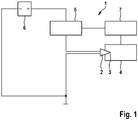
- FIG. 1 A glow plug 2 protrudes into the combustion chamber 3 of the diesel engine 4.
- the glow plug 2 is on the one hand connected to the Glühzeit Kunststoff réelle 5 and on the other hand leads to a battery 6, which controls the glow plug 2 with the rated voltage of, for example, 11 volts.
- the Glühzeit Kunststoff réelle 5 is connected to the engine control unit 7, which in turn leads to the diesel engine 4.
- the glow plug 2 is preheated by the application of an overvoltage in a, also referred to as a push phase preheating, which lasts 1 to 2 seconds.
- the electrical energy that is supplied to the glow plug 2 is thus converted into heat in a heating coil, not shown, which is why the temperature at the top of the glow plug 2 rises steeply.
- the heating power of the heating coil is adjusted via the electronic Glühzeit Kunststoff 5 to the requirement of the respective diesel engine 4.
- the fuel-air mixture is conducted past the hot tip of the glow plug 2 and heats up. Associated with an intake air heating during the compressor stroke of the diesel engine 4, the ignition temperature of the fuel-air mixture is achieved.
- the glow plug 2 has different glow phases. As already stated, in a preheating phase, which takes 1 to 2 seconds, the cold glow plug 2 is supplied with an overvoltage, which is above the rated voltage of the glow plug 2. During this short period of time, the tip of the glow plug is heated to approximately 1000 ° C, while the remaining part of the glow plug 2 is still below this temperature, thereby forming a transient temperature profile within the glow plug 2.
- This preheating phase is followed by a heating phase of the glow plug 2, in which the transient temperature distribution compensates for a steady temperature distribution over the entire glow plug 2. Such a heating phase usually takes approximately 30 seconds.
- the resistance difference is adjusted dynamically in the heating phase. This is followed by the annealing phase, in which a steady temperature distribution over the entire glow plug is ensured.
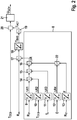
- FIG. 2 a schematic diagram for the temperature modeling of the glow plug 2 during the rapid preheat phase is shown, which is integrated as software in the engine control unit 7 or the Glühzeit Kunststoff Technology 5 and is taken into account in a temperature control of the glow plug.
- a temperature setpoint T DES is provided by the engine control unit 7.
- a resistance R m of the glow plug is measured, which represents a value for the current temperature at the glow plug 2. This measured resistance R m is determined at each Bestromungsvorgang, which takes place at regular intervals.
- this measured resistance R m is added to a resistance difference ⁇ R, which is determined by means of a predictive model 8.
- This predictive model 8 models the temperature of the glow plug 2 in the rapid preheat phase.
- This initial resistance R 01 is determined.
- This initial resistance R 01 is fed to a characteristic curve 9, which was determined during stationary operation of the glow plug. From this characteristic curve 9, a first partial resistance difference ⁇ R1 is determined on the basis of the measured initial resistance R 01 .
- the temperature setpoint T DES is provided which characterizes the end temperature of the glow plug 2 to be reached.
- This temperature setpoint T DES is also given to a further characteristic curve 10 as input variable, from which a second partial resistance difference ⁇ R2 is determined.
- the thus determined partial resistance differences ⁇ R1 and ⁇ R2 are added in block 14.
- the third partial resistance difference ⁇ R3 is determined by means of a third characteristic 11.
- the third partial resistance difference ⁇ R3 is added to the first and the second partial resistance difference ⁇ R1 and ⁇ R2.
- an annealing time / annealing energy E U * 1 * t
- E U * 1 * t
- the resistor R 01 is another characteristic thirteenth which as a result yields a factor F which is multiplied in block 22 by the fourth partial resistance difference ⁇ R4.
- the factor F is selected so that when the time measured initial resistance R is greater than a predetermined threshold value of the resistor R 01 01, this is equal to the first The factor F tends towards the value zero, when the initial resistance R 01 is less than the predetermined threshold value of the resistor R 01.
- the fourth partial resistance difference ⁇ R4 is added in block 16 to the above-described partial resistance difference ⁇ R1, ⁇ R2 and ⁇ R3, resulting in a resistance difference ⁇ R corresponding to a predetermined temperature occurring at the end of the preheating operation on the glow plug 2.
- the determined in the predictive model 8 resistance difference ⁇ R is added in block 17 to the measured resistance R m .
- This sum of the resistance difference .DELTA.R and the measured resistance R m is supplied to a characteristic curve 18, in which the resistance is plotted against the temperature.
- This characteristic curve 18 is a characteristic determined individually for each glow plug 2 at a steady-state temperature distribution, since glow plugs have an independent transfer function due to production tolerances.
- a base temperature T BAS of the glow plug 2 is determined.
- This base temperature T BAS is compared in block 19 with a heat conduction model, which takes into account the extent to which there is a temperature difference between the interior of the heater of the glow plug 2 and the surface temperature of the glow plug 2.
- a temperature difference is supplied in block 19 to the base temperature T BAS , the sum of which results in the actual temperature T ACT of the glow plug 2.
- This actual temperature T ACT is now used in the control cycle, where it is subtracted from the temperature setpoint T DES in block 20.
- the difference between the temperature setpoint T DES and the actual temperature T ACT is supplied to a controller 21, which determines a voltage U GOV which is supplied to the glow plug 2, in particular the heater of the glow plug 2, for rapid adjustment of the temperature setpoint T DES .
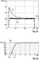
- FIG. 3 shows two temperature-time diagrams in which the measured temperature Tm once without predictive modeling ( FIG. 3a ) and once with predictive modeling ( FIG. 3b ) is shown.
- FIG. 3a It can be seen that the measured temperature Tm, which is to be matched to the temperature set point T Des, shortly after the beginning of the annealing process has a temperature overshoot which is approaching the temperature setpoint T Des only after a time of about 30 seconds.
- the mathematically FIG. 2 modeled temperature Tmo is shown without model 8, which after the preheating phase, approximately after 5 seconds, reaches and regulates the level of the temperature setpoint T Des .
- FIG. 3b shows the course of the measured temperature Tm in the consideration of the predictive determined by means of the predictive temperature model 8 resistance difference .DELTA.R.
- the measured temperature Tm shows no temperature overshoot, but approaches immediately after the Preheating phase of the modeled temperature Tm.
- the temperature setpoint T Des is reached by means of this control and is regulated by this.
- a temperature control of the glow plug 2 not only during stationary operation, in which no more resistance-temperature fluctuations, but also in transient operation, preferably in the rapid preheating at the beginning of the annealing process and during to carry out the heating phase.
- the temperature modeling of the glow plug 2 in the rapid preheating phase it is modeled how large the resistance difference .DELTA.R will be at the end of the preheating process, this difference in resistance .DELTA.R being supplied as input to the control process.
Landscapes
- Engineering & Computer Science (AREA)
- Chemical & Material Sciences (AREA)
- Combustion & Propulsion (AREA)
- Mechanical Engineering (AREA)
- General Engineering & Computer Science (AREA)
- Combined Controls Of Internal Combustion Engines (AREA)
- Ignition Installations For Internal Combustion Engines (AREA)
- Resistance Heating (AREA)
- Control Of Resistance Heating (AREA)
Description
Die Erfindung betrifft ein Verfahren zur Einstellung einer Temperatur einer Glühstiftkerze, insbesondere zur Zündung eines Kraftstoff-Luft-Gemisches in einem Verbrennungsmotor, bei welchem die Temperatur der Glühstiftkerze in Abhängigkeit eines Widerstandes der Glühstiftkerze mittels einer Regelung eingestellt wird, sowie ein Steuergerät zur Durchführung des Verfahrens.The invention relates to a method for adjusting a temperature of a glow plug, in particular for igniting a fuel-air mixture in an internal combustion engine, wherein the temperature of the glow plug is adjusted in response to a resistance of the glow plug by means of a control, and a control device for carrying out the method ,
Glühstiftkerzen, welche in Verbrennungsmotoren zur Zündung eines Kraftstoff-Luft-Gemisches eingesetzt werden, werden in kaltem Zustand vorgeglüht, bevor ihre Temperatur so hoch ist, dass es für die Zündung des Kraftstoff-Luft-Gemisches ausreicht. Die Glühstiftkerze weist dazu einen Heizer auf, welcher die kalte Glühstiftkerze in einer kurzen Zeitspanne von 1 bis 2 Sekunden mit einer überhöhten Heizspannung beaufschlagt, so dass die Glühstiftkerze zu diesem Zeitpunkt überbeansprucht wird. Nach Abschluss dieser sogenannten Push-Phase hat die Spitze der Glühstiftkerze eine Temperatur von über 1000°C erreicht, während der restliche Teil der Glühstiftkerze noch eine Temperatur aufweist, die weit unterhalb dieser Temperatur von 1000°C liegt.Glow plugs, which are used in internal combustion engines to ignite a fuel-air mixture are preheated in a cold state before their temperature is so high that it is sufficient for the ignition of the fuel-air mixture. The glow plug has for this purpose a heater, which acts on the cold glow plug in a short period of 1 to 2 seconds with an excessive heating voltage, so that the glow plug is overstressed at this time. After completion of this so-called push phase, the tip of the glow plug has reached a temperature of about 1000 ° C, while the remaining part of the glow plug still has a temperature which is well below this temperature of 1000 ° C.
Durch die Ansteuerung der Glühstiftkerze mit einer überhöhten Heizspannung entsteht ein Temperaturüberschwinger an der Glühstiftkerze. Die in der Vorheizphase erlangte Temperatur der Glühstiftkerze stellt eine Eingangsgröße für eine Regelung dar, mit welcher die Temperatur der Glühstiftkerze eingestellt wird, wie z.B. in
Der Erfindung liegt somit die Aufgabe zugrunde, ein Verfahren zur Regelung der Temperatur einer Glühstiftkerze anzugeben, bei welchem der während der Vorheizphase auftretende Temperaturüberschwinger zuverlässig unterbunden wird, obwohl die Glühstiftkerze mit einer überhöhten Heizspannung beaufschlagt wird.The invention is therefore an object of the invention to provide a method for controlling the temperature of a glow plug in which the occurring during the preheating temperature overshoot is reliably prevented, although the glow plug is subjected to an excessive heating voltage.
Erfindungsgemäß wird die Aufgabe dadurch gelöst, dass die Temperatur in einer Vorheizphase der Glühstiftkerze, in welcher eine Überspannung an die Glühstiftkerze angelegt wird, geregelt wird. Der Vorteil der Erfindung besteht darin, dass die Glühtemperatur über den gesamten Glühvorgang der Glühstiftkerze nun mit hoher Güte moduliert wird und die Regelung der Glühtemperatur zu jedem Zeitpunkt der Glühphase, vorteilhafterweise auch in der Vorheizphase (Push-Phase) erfolgt, bei welcher der Heizer der Glühstiftkerze die kalte Glühstiftkerze in einer kurze Zeitspanne von 1 bis 2 Sekunden mit einer überhöhten Heizspannung beaufschlagt. Dies ermöglicht eine bessere Beherrschung der Vorheizphase sowohl beim Schlüsselstart als auch bei langen Startphasen. Erfindungsgemäß wird zur Regelung der Temperatur der Glühstiftkerze in der Vorheizphase eine Widerstandsdifferenz, welche am Ende der Vorheizphase zu einem gemessenen Widerstand besteht, mit Hilfe eines physikalischen Modells während der Vorheizphase vorausschauend bestimmt. Somit wird die Temperatur in der Vorheizphase, in welcher eine Überspannung an die Glühstiftkerze angelegt wird, mit Hilfe des prädiktiven Modells geregelt. Dadurch ist die Vorheizphase der Glühstiftkerze robuster, da keine oder nur geringe Temperaturüberschwinger auftreten und es werden exakte Eingangswerte für die Regelung auch im weiteren Glühverlauf der Glühstiftkerze bereitgestellt. Somit wird die Regelung bereits in der Vorheizphase eng auf den gewünschten Temperatursollwert ausgerichtet. Durch die Bestimmung der Widerstandsdifferenz wird die Eingangsgröße des Widerstandes für die Regelung initialisiert und der Zeitpunkt bei der Erstbestromung der Glühstiftkerze mit berücksichtigt. Weiterhin wird der Entwicklungsaufwand reduziert, da keine Applikation für ein gesteuertes Vorheizen notwendig wird und die Eingangsparameter nur einmal bestimmt und für die Lebensdauer der Glühstiftkerze beibehalten werden. Erfindungsgemäß wird der gemessene Widerstand der Glühstiftkerze mit der Widerstandsdifferenz addiert und die aus dem gemessenen Widerstand und der Widerstandsdifferenz gebildete Summe der Regelung zugeführt. Dadurch wird der gemessene Widerstand um einen vorausschauend bestimmten Betrag erhöht, welcher der tatsächlich während der Vorheizphase in der Glühstiftkerze auftretenden Temperatur entspricht. Erindungsgemäß wird aus einer Kennlinie, welche individuell für jede Glühstiftkerze im aufgeheizten, stationären Betrieb der Glühstiftkerze bestimmt wird, anhand der Summe aus dem gemessenen Widerstand und der Widerstandsdifferenz, ein Temperaturistwert ermittelt, welcher vom Temperatursollwert subtrahiert wird, wobei die so ermittelte Temperaturdifferenz der Regelung zugeführt wird, aus welcher eine Ansteuerspannung für die Glühstiftkerze ermittelt wird, um den gewünschten Temperatursollwert einzustellen. Die Einbindung der Widerstandsdifferenz in die Bestimmung des Temperaturistwertes führt dazu, dass auch während der schnellen Vorheizphase eine Regelung der Temperatur der Glühstiftkerze gewährleistet werden kann.According to the invention the object is achieved in that the temperature in a preheating the glow plug, in which an overvoltage is applied to the glow plug, is regulated. The advantage of the invention is that the annealing temperature over the entire annealing of the glow plug is now modulated with high quality and the control of the annealing temperature at each time the annealing phase, advantageously also in the preheating (push phase) takes place, in which the heater of the Glow plug, the cold glow plug in a short period of 1 to 2 seconds applied to an excessive heating voltage. This allows better control of the preheat phase both at the key start and during long startup phases. According to the invention, to regulate the temperature of the glow plug in the preheating phase, a resistance difference, which at the end of the preheating phase results in a measured resistance, is determined with the aid of a physical model during the preheating phase. Thus, the temperature in the preheat phase, in which an overvoltage is applied to the glow plug, is controlled by means of the predictive model. As a result, the preheating phase of the glow plug is more robust, since no or only small temperature overshoot occur and there are provided accurate input values for the control in the further course of the glow plug glow. Thus, the control is already aligned closely to the desired temperature setpoint in the preheating phase. By determining the resistance difference, the input variable of the resistor for the control is initialized and the time at the first energization of the glow plug is taken into account. Furthermore, the development effort is reduced because no application for a controlled preheating is necessary and the input parameters are determined only once and maintained for the life of the glow plug. According to the invention, the measured resistance of the glow plug is added to the resistance difference and fed the sum of the control formed from the measured resistance and the resistance difference. Thereby, the measured resistance is increased by an anticipated certain amount, which corresponds to the temperature actually occurring during the preheating phase in the glow plug. Erindungsgemäß is determined from a characteristic curve, which is determined individually for each glow plug in the heated, steady operation of the glow plug, based on the sum of the measured resistance and the resistance difference, a Temperaturistwert which is subtracted from the temperature setpoint, wherein the thus determined temperature difference of the control is determined from which a drive voltage for the glow plug to set the desired temperature setpoint. The integration of the resistance difference in the determination of the temperature actual value means that even during the rapid preheating phase, a regulation of the temperature of the glow plug can be ensured.
In einer Weiterbildung besteht die Widerstandsdifferenz aus mehreren, insbesondere summierten, Teilwiderstandsdifferenzen, wobei jede Teilwiderstandsdifferenz in Abhängigkeit mindestens eines Betriebsparameters der Glühstiftkerze bestimmt wird. Dadurch wird der Zustand der Glühstiftkerze zum Start eines Glühvorganges bei der Erstbestromung der Glühstiftkerze charakterisiert und unter Anwendung von entsprechenden Kennlinien optimiert.In a further development, the resistance difference consists of several, in particular summed, partial resistance differences, wherein each partial resistance difference is determined as a function of at least one operating parameter of the glow plug. As a result, the state of the glow plug is characterized to start an annealing process in the Erstbestromung the glow plug and optimized using appropriate characteristics.
In einer Variante wird eine erste Teilwiderstandsdifferenz in Abhängigkeit eines Energiegehaltes der Glühstiftkerze bestimmt, welchen diese zum Zeitpunkt des Startes des Glühvorganges aufweist. Dadurch wird die Anfangscharakteristik der Glühstiftkerze zum Zeitpunkt des Starts des Glühvorganges bei der Bestimmung der Widerstandsdifferenz berücksichtigt.In a variant, a first partial resistance difference is determined as a function of an energy content of the glow plug which it has at the time of starting the annealing process. As a result, the initial characteristic of the glow plug at the time of starting the annealing process in the determination of the resistance difference is taken into account.
Insbesondere wird der Energiegehalt der Glühstiftkerze durch einen Anfangswiderstand, eine Anfangswärmemenge oder eine Anfangsleistung charakterisiert. Somit wird der Wärmehaushalt der kalten Glühstiftkerze vor der Erstbestromung berücksichtigt. Da beispielsweise bei einer kalten Glühstiftkerze der Anfangswiderstand sehr klein ist, während bei einer Glühstiftkerze, die schon einmal angeheizt wurde, der Anfangswiderstand größer ist, wird sichergestellt, dass immer die korrekte Eingangsgröße bei der Bestimmung der Widerstandsdifferenz herangezogen wird.In particular, the energy content of the glow plug is characterized by an initial resistance, an initial amount of heat or an initial power. Thus, the heat balance of the cold glow plug is considered before Erstbestromung. For example, since in a cold glow plug the initial resistance is very small, while in a glow plug, which was once heated, the initial resistance is greater, it ensures that always the correct input variable is used in determining the resistance difference.
In einer anderen Ausführungsform wird eine zweite Teilwiderstandsdifferenz in Abhängigkeit eines Temperatursollwertes der Glühstiftkerze bestimmt, welchen diese am Ende des Glühvorganges aufweisen soll. Durch die Einbeziehung des Temperatursollwertes wird bei der Modellierung sichergestellt, dass auch der zu erreichende Endzustand der Glühstiftkerze in Form des Temperatursollwertes, welcher der Temperatur entspricht, die am Ende des der Vorheizphase folgenden Aufheizvorganges der Glühstiftkerze eingestellt sein soll, berücksichtigt wird.In another embodiment, a second partial resistance difference is determined as a function of a temperature setpoint of the glow plug, which it should have at the end of the annealing process. By including the Temperature setpoint is ensured in the modeling, that also the final state of the glow plug to be reached in the form of the temperature setpoint, which corresponds to the temperature to be set at the end of the preheating subsequent heating operation of the glow plug is taken into account.
Ferner wird eine dritte Teilwiderstandsdifferenz in Abhängigkeit einer Ausgangstemperatur der Glühstiftkerze bestimmt, welchen diese zum Zeitpunkt des Startes des Glühvorganges aufweist. Da die Glühstiftkerze bei unterschiedlichen Temperaturen beim Erststart ein unterschiedliches Verhalten aufweist, wird diese Ausgangstemperatur der Glühstiftkerze ebenfalls berücksichtigt, um das richtige Verhalten der Glühstiftkerze modellieren zu können.Furthermore, a third partial resistance difference is determined as a function of an output temperature of the glow plug which it has at the time of starting the annealing process. Since the glow plug has a different behavior at different temperatures at the first start, this output temperature of the glow plug is also taken into account in order to model the correct behavior of the glow plug.
Insbesondere entspricht die Ausgangstemperatur einer Umgebungstemperatur der Glühstiftkerze zum Zeitpunkt des Startes des Glühvorganges. Die Umgebungstemperatur der Glühstiftkerze ist einfach zu ermitteln, da Kraftfahrzeuge, in dessen Verbrennungsmotoren die Glühstiftkerzen eingebaut sind, über eine Außentemperaturanzeige verfügen. Somit kann auf weitere Hardware zur Bestimmung der Umgebungstemperatur verzichtet werden.In particular, the starting temperature corresponds to an ambient temperature of the glow plug at the time of starting the annealing process. The ambient temperature of the glow plug is easy to determine, since motor vehicles in whose internal combustion engines the glow plugs are installed have an outside temperature display. Thus, it is possible to dispense with further hardware for determining the ambient temperature.
Vorteilhafterweise wird eine vierte Teilwiderstandsdifferenz in Abhängigkeit eines, dem Start des Glühvorganges unmittelbar vorausgegangenen Glühvorganges der Glühstiftkerze bestimmt. Damit wird insbesondere dem Zustand der Glühstiftkerze Rechnung getragen, welcher die Glühstiftkerze aufweist, wenn die Zündung des Verbrennungsmotors, welche ein Aufheizen der Glühstiftkerze nach sich zieht, erfolgt ist, diese kurze Zeit später aber wieder ausgeschaltet wurde und innerhalb weniger Augenblicke wiederum aktiviert wurde.Advantageously, a fourth partial resistance difference is determined as a function of an annealing process of the glow plug that is directly preceded by the start of the annealing process. Thus, in particular, the state of the glow plug is taken into account, which has the glow plug when the ignition of the engine, which pulls a heating of the glow plug by itself, has taken place, but this short time later turned off again and was activated within a few moments again.
In einer Ausgestaltung wird der unmittelbar vorausgegangene Glühvorgang durch dessen Glühdauer oder Glühenergie charakterisiert, wobei in Abhängigkeit eines Anfangswiderstandes der Glühstiftkerze ein Faktor bestimmt wird, welcher mit der vierten Teilwiderstandsdifferenz multipliziert wird und zu der Widerstandsdifferenz addiert wird. Die Glühdauer, welche der Einschaltdauer der Glühstiftkerze entspricht, erlaubt Rückschlüsse darauf, wie viel Energie noch in der Glühstiftkerze gespeichert ist. Je nachdem, wie groß der während der vorausgegangenen Glühdauer der Glühstiftkerze eingestellte Ausgangswiderstand ist, wird die vierte Teilwiderstandsdifferenz, die in Abhängigkeit von der dem Start des Glühvorganges vorausgegangenen Glühdauer ermittelt wurde, zu der Widerstandsdifferenz hinzu addiert.In one embodiment, the immediately preceding annealing process is characterized by its annealing duration or annealing energy, wherein a factor is determined in dependence on an initial resistance of the glow plug, which is multiplied by the fourth partial resistance difference and added to the resistance difference. The annealing time, which corresponds to the duty cycle of the glow plug, allows conclusions about how much energy is still stored in the glow plug. Depending on how large the set during the previous annealing period of the glow plug output resistance, the fourth partial resistance difference, which was determined in dependence on the start of the annealing preceding annealing time, added to the resistance difference.
Eine Weiterbildung der Erfindung betrifft ein Steuergerät zur Einstellung einer Temperatur einer Glühstiftkerze nach Anspruch 10. Die Erfindung lässt zahlreiche Ausführungsformen zu. Eine davon soll anhand der in der Zeichnung dargestellten Figuren näher erläutert werden.A development of the invention relates to a control device for adjusting a temperature of a glow plug according to
Es zeigt:
- Figur 1:
- Prinzipdarstellung der Anordnung einer Glühstiftkerze in einem Verbrennungsmotor
- Figur 2:
- schematische Darstellung zur Modellierung der Temperatur einer Glühstiftkerze in einer schnellen Vorheizphase
- Figur 3:
- Temperatur-Zeit-Diagramm ohne und mit prädiktiver Temperaturmodellierung
- FIG. 1:
- Schematic representation of the arrangement of a glow plug in an internal combustion engine
- FIG. 2:
- schematic representation for modeling the temperature of a glow plug in a fast preheat phase
- FIG. 3:
- Temperature-time diagram with and without predictive temperature modeling
Kalte Verbrennungsmotoren, insbesondere Dieselmotoren, benötigen bei Umgebungstemperaturen von <40°C eine Starthilfe zur Zündung des in den Dieselmotor eingeleiteten Kraftstoff-Luft-Gemisches. Als Starthilfe werden dann Glühsysteme eingesetzt, welche aus Glühstiftkerzen, einem Glühzeitsteuergerät und einer Glühsoftware, welche in einem Motorsteuergerät oder dem Glühzeitsteuergerät abgelegt ist, bestehen. Außerdem werden Glühsysteme auch zur Verbesserung der Emission des Fahrzeuges genutzt. Weitere Einsatzgebiete des Glühsystems bestehen im Brennerabgassystem, bei der Standheizung, bei der Vorwärmung für Kraftstoff (flex fuel) oder der Vorwärmung des Kühlwassers.Cold internal combustion engines, in particular diesel engines, require a start-up aid for ignition of the fuel-air mixture introduced into the diesel engine at ambient temperatures of <40 ° C. As starting aid then glow systems used, which consist of glow plugs, a Glühzeitsteuergerät and annealing software, which is stored in an engine control unit or the Glühzeitsteuergerät consist. In addition, annealing systems are also used to improve the emission of the vehicle. Further fields of application of the glow system are the burner exhaust system, the auxiliary heating, the preheating of fuel (flex fuel) or the preheating of the cooling water.
Zur Zündung des Kraftstoff-Luft-Gemisches wird die Glühstiftkerze 2 in einer, auch als Push-Phase bezeichneten Vorheizphase, die 1 bis 2 Sekunden dauert, durch das Anlegen einer Überspannung vorgeheizt. Die elektrische Energie, die der Glühstiftkerze 2 somit zugeführt wird, wird in einer nicht weiter dargestellten Heizwendel in Wärme umgewandelt, weshalb die Temperatur an der Spitze der Glühstiftkerze 2 steil ansteigt. Die Heizleistung der Heizwendel wird über das elektronische Glühzeitsteuergerät 5 an die Anforderung des jeweiligen Dieselmotors 4 angepasst. Das Kraftstoff-Luft-Gemisch wird an der heißen Spitze der Glühstiftkerze 2 vorbeigeleitet und erwärmt sich dabei. Verbunden mit einer Ansauglufterwärmung während des Verdichtertaktes des Dieselmotors 4 wird die Entflammungstemperatur des Kraftstoff-Luft-Gemisches erreicht.To ignite the fuel-air mixture, the
Die Glühstiftkerze 2 weist verschiedene Glühphasen auf. Wie bereits dargestellt, wird in einer Vorheizphase, die 1 bis 2 Sekunden in Anspruch nimmt, der kalten Glühstiftkerze 2 eine Überspannung zugeführt, welche oberhalb der Nennspannung der Glühstiftkerze 2 liegt. Während dieses kurzen Zeitraumes wird die Spitze der Glühstiftkerze auf annähernd 1000°C erhitzt, während der restliche Teil der Glühstiftkerze 2 noch unterhalb dieser Temperatur liegt, wodurch sich ein instationärer Temperaturverlauf innerhalb der Glühstiftkerze 2 ausbildet. An diese Vorheizphase schließt sich eine Aufheizphase der Glühstiftkerze 2 an, in welcher die instationäre Temperaturverteilung sich zu einer stationären Temperaturverteilung über die gesamte Glühstiftkerze 2 ausgleicht. Eine solche Aufheizphase dauert normalerweise annähernd 30 Sekunden. Nach der Vorheizphase der Glühstiftkerze wird die Widerstandsdifferenz dynamisch in der Aufheizphase angepasst. Daran schließt sich die Glühphase an, bei welcher eine stationäre Temperaturverteilung über die gesamte Glühstiftkerze gewährleistet ist.The
In
Als weitere Eingangsgröße des prädiktiven Modells 8 ist der Temperatursollwert TDES vorgesehen, welcher die zu erreichende Endtemperatur der Glühstiftkerze 2 kennzeichnet. Auch dieser Temperatursollwert TDES wird auf eine weitere Kennlinie 10 als Eingangsgröße gegeben, aus welcher eine zweite Teilwiderstandsdifferenz ΔR2 ermittelt wird. Die so ermittelten Teilwiderstandsdifferenzen ΔR1 und ΔR2 werden im Block 14 addiert.As a further input variable of the
Neben den schon genannten Eingangsgrößen in Form des Anfangswiderstandes R01 und des Temperatursollwertes TDES wird die Betriebstemperatur TC der Glühstiftkerze 2 zum Zeitpunkt des Startes des Glühvorganges also zum Zeitpunkt t=0 bestimmt. Aus dieser Temperatur TC wird mit Hilfe einer dritten Kennlinie 11 die dritte Teilwiderstandsdifferenz ΔR3 bestimmt. Im Block 15 wird die dritte Teilwiderstandsdifferenz ΔR3 zu der ersten und der zweiten Teilwiderstandsdifferenz ΔR1 und ΔR2 hinzu addiert. Diese Eingangsgrößen in Form des Anfangswiderstandes R01, des Temperatursollwertes TDES und der Umgebungstemperatur TC werden einmalig zum Zeitpunkt t=0 - bei Aktivierung der Glühstiftkerze 2 - bestimmt und können im Motorsteuergerät 7 oder dem Glühzeitsteuergerät 5 abgespeichert werden.In addition to the already mentioned input variables in the form of the initial resistance R 01 and the temperature setpoint T DES , the operating temperature T C of the
Um zu berücksichtigen, dass die Glühstiftkerze 2 bereits kurz vor dem auszuführenden Glühvorgang schon einmal einem Glühvorgang unterworfen wurde, aus welchem die Glühstiftkerze 2 noch nicht ausreichend abgekühlt ist, wird eine Glühzeit/Glühenergie E (E = U * l * t) des, dem aktuellen Glühvorgang unmittelbar vorausgegangenen Glühvorgangs der Glühstiftkerze 2 berücksichtigt. Aus der Glühzeit/ Glühenergie E wird mit Hilfe einer vierten Kennlinie 12 eine vierte Teilwiderstandsdifferenz ΔR4 bestimmt. Da aufgrund der Glühzeit/Glühenergie E des unmittelbar vorangegangenen Glühvorganges sich der Widerstand der Glühstiftkerze 2 verändert, wenn die Wärme, die sich während des vorausgegangenen Glühvorganges innerhalb der Glühstiftkerze 2 aufgebaut hat, noch nicht abgekühlt ist, wird der Widerstand R01 einer weiteren Kennlinie 13 zugeführt, welcher als Ergebnis einen Faktor F liefert, der im Block 22 mit der vierten Teilwiderstandsdifferenz ΔR4 multipliziert wird. Der Faktor F ist dabei so gewählt, dass wenn der einmal gemessene Anfangswiderstand R01 größer als ein vorgegebener Schwellwert des Widerstandes R01 ist, dieser gleich 1 beträgt. Der Faktor F strebt gegen den Wert Null, wenn der Anfangswiderstand R01 kleiner ist als der vorgegebene Schwellwert des Widerstandes R01. Dies bedingt, dass die Eingangsgrößen der Glühzeit/Glühenergie E mit der dabei verbundenen Veränderung des Anfangswiderstandes R01 nur dann zur Bestimmung der Widerstandsdifferenz ΔR herangezogen werden, wenn die Glühstiftkerze 2 aufgrund eines vorangegangenen Glühvorganges noch einen entsprechend großen Widerstand aufweist, welcher mit einer veränderten Temperatur der Glühstiftkerze 2 einhergeht. Die vierte Teilwiderstandsdifferenz ΔR4 wird im Block 16 zu den zuvor beschriebenen Teilwiderstandsdifferenz ΔR1, ΔR2 und ΔR3 hinzuaddiert, woraus sich eine Widerstandsdifferenz ΔR ergibt, die einer vorausbestimmten Temperatur entspricht, welche zum Ende des Vorheizvorganges an der Glühstiftkerze 2 auftritt.In order to take into account that the
Die im prädiktiven Modell 8 bestimmte Widerstandsdifferenz ΔR wird im Block 17 zu dem gemessenen Widerstand Rm hinzuaddiert. Diese Summe aus der Widerstandsdifferenz ΔR und dem gemessenen Widerstand Rm wird einer Kennlinie 18 zugeführt, in welcher der Widerstand über der Temperatur aufgetragen ist. Bei dieser Kennlinie 18 handelt es sich um eine individuell, für jede Glühstiftkerze 2 bei einer stationären Temperaturverteilung ermittelte Kennlinie, da Glühstiftkerzen aufgrund von Produktionstoleranzen eine eigenständige Übertragungsfunktion aufweisen. Aus dieser Widerstands-/Temperatur-Kennlinie 18 wird eine Basistemperatur TBAS der Glühstiftkerze 2 ermittelt. Diese Basistemperatur TBAS wird im Block 19 mit einem Wärmeleitungsmodell abgeglichen, bei welchem berücksichtigt wird, inwieweit eine Temperaturdifferenz zwischen dem Inneren des Heizers der Glühstiftkerze 2 und der Oberflächentemperatur der Glühstiftkerze 2 besteht. Dabei wird im Block 19 der Basistemperatur TBAS eine Temperaturdifferenz zugeführt, aus deren Summe sich die Isttemperatur TACT der Glühstiftkerze 2 ergibt. Diese Isttemperatur TACT wird nun in dem Regelzyklus verwendet, wo sie im Block 20 von dem Temperatursollwert TDES subtrahiert wird. Die Differenz zwischen dem Temperatursollwert TDES und der Isttemperatur TACT wird einem Regler 21 zugeführt, welcher eine Spannung UGOV bestimmt, die der Glühstiftkerze 2, insbesondere dem Heizer der Glühstiftkerze 2, zur schnellen Einstellung des Temperatursollwertes TDES zugeführt wird.The determined in the
Im Gegensatz dazu zeigt
Aufgrund des prädiktiven Modells 8 ist es möglich, dass eine Temperaturregelung der Glühstiftkerze 2 nicht nur während des stationären Betriebes, bei welchem keine Schwankungen zwischen Widerstand und Temperatur mehr auftreten, sondern auch im instationären Betrieb, vorzugsweise in der schnellen Vorheizphase zu Beginn des Glühvorganges und während der Aufheizphase durchzuführen. Bei der Temperaturmodellierung der Glühstiftkerze 2 in der schnellen Vorheizphase wird modelliert, wie groß die Widerstandsdifferenz ΔR am Ende des Vorheizvorganges sein wird, wobei diese Widerstandsdifferenz ΔR als Eingangsgröße dem Regelvorgang zugeführt wird.Due to the
Claims (10)
- Method for adjusting a temperature of a glow plug, in particular for igniting a fuel/air mixture in an internal combustion engine, in which the temperature (Tm) of the glow plug (2) is adjusted as a function of a resistance (Rm) of the glow plug (2) by means of a regulating device, wherein the temperature (Tm) is regulated in a pre-heating phase in which an overvoltage is applied to the glow plug (2), characterized in that in order to regulate the temperature (Tm) of the glow plug (2) in the pre-heating phase a difference in resistance (ΔR), which is present with respect to a measured resistance (Rm) at the end of the pre-heating phase, is determined predictably using a physical model (8) during the pre-heating phase, in that the measured resistance (Rm) of the glow plug (2) is added to the difference in resistance (ΔR), and the sum which is formed from the measured resistance (Rm) and the difference in resistance (ΔR) is fed to the regulating device, in that an actual temperature value (TACT), which is subtracted from a temperature setpoint value (Tdes) of the glow plug, is determined from a characteristic curve (18), which is determined individually for each glow plug (2) during the heated, steady-state operation of the glow plug (2), on the basis of the sum of the measured resistance (Rm) and the difference in resistance (ΔR), wherein the temperature difference which is determined in this way is fed to the regulating device and is used to determine an actuation voltage (UGOV) for the glow plug (2).
- Method according to Claim 1, characterized in that the difference in resistance (ΔR) is composed of a plurality of, in particular summed, partial resistance differences (ΔR1, AR2, ΔR3, ΔR4), wherein each partial resistance difference (ΔR1, AR2, ΔR3, ΔR4) is determined as a function of at least one operating parameter (R01, TDes, Tc, E, R02) of the glow plug (2).
- Method according to Claim 2, characterized in that a first partial resistance difference (ΔR1) is determined as a function of an energy content of the glow plug (2) which said glow plug (2) has at the time of starting the glowing process.
- Method according to Claim 3, characterized in that the energy content of the glow plug (2) is characterized by an initial resistance (R01), an initial quantity of heat or an initial power of the glow plug (2).
- Method according to Claim 2, 3 or 4, characterized in that a second partial resistance difference (ΔR2) is determined as a function of a temperature setpoint value (TDes) of the glow plug (2) which said glow plug (2) has at the end of the glowing process.
- Method according to at least one of the preceding Claims 2 to 5, characterized in that a third partial resistance difference (ΔR3) is determined as a function of an initial temperature (Tc) of the glow plug (2) which said glow plug (2) has at the time of the start of the glowing process.
- Method according to Claim 5, characterized in that the initial temperature (Tc) corresponds to an ambient temperature of the glow plug (2) at the time of the start of the glowing process.
- Method according to at least one of the preceding Claims 2 to 7, characterized in that a fourth partial resistance difference (ΔR4) is determined as a function of a glowing process of the glow plug (2) which directly precedes the start of the glowing process.
- Method according to Claim 8, characterized in that the directly preceding glowing process is characterized by the glowing duration or glowing energy (E) thereof, wherein a factor (F) which is multiplied by the fourth partial resistance difference (ΔR4) and added to the resistance difference (ΔR) is determined, in particular, as a function of the initial resistance (R01) of the glow plug (2).
- Control device for adjusting a temperature of a glow plug, in particular for igniting a fuel/air mixture in an internal combustion engine which adjusts the temperature (Tm) of the glow plug (2) as a function of a resistance (Rm) of the glow plug (2) by means of a regulating device, wherein means (8, 21) are present which regulate the temperature (Tm) in a pre-heating phase in which an overvoltage is applied to the glow plug (2), characterized in that means for regulating the temperature (Tm) of the glow plug (2) in the pre-heating phase are embodied in such a way that they predictively determine a difference in resistance (ΔR), which is present with respect to a measured resistance (Rm) at the end of the pre-heating phase, using a physical model (8) during the pre-heating phase, add the measured resistance (Rm) of the glow plug (2) to the difference in resistance (ΔR) and feed the sum which is formed from the measured resistance (Rm) and the difference in resistance (ΔR) to the regulating device, determine an actual temperature value (TACT) from a characteristic curve (18), which is determined individually for each glow plug (2) during the heated, steady-state operation of the glow plug (2), on the basis of the sum of the measured resistance (Rm) and the difference in resistance (ΔR) and subtract it from a temperature setpoint value (TDes) of the glow plug, and feed the temperature difference, which is determined in this way and is used to determine an actuation voltage (UGOV) for the glow plug (2), to the regulating device.
Applications Claiming Priority (2)
| Application Number | Priority Date | Filing Date | Title |
|---|---|---|---|
| DE102011004514A DE102011004514A1 (en) | 2011-02-22 | 2011-02-22 | Method and control unit for setting a temperature of a glow plug |
| PCT/EP2012/052212 WO2012113653A1 (en) | 2011-02-22 | 2012-02-09 | Method and control device for adjusting a temperature of a glow plug |
Publications (2)
| Publication Number | Publication Date |
|---|---|
| EP2678552A1 EP2678552A1 (en) | 2014-01-01 |
| EP2678552B1 true EP2678552B1 (en) | 2018-04-18 |
Family
ID=45607241
Family Applications (1)
| Application Number | Title | Priority Date | Filing Date |
|---|---|---|---|
| EP12704047.5A Active EP2678552B1 (en) | 2011-02-22 | 2012-02-09 | Method and control device for adjusting a temperature of a glow plug |
Country Status (6)
| Country | Link |
|---|---|
| US (1) | US10132288B2 (en) |
| EP (1) | EP2678552B1 (en) |
| JP (1) | JP5815752B2 (en) |
| CN (1) | CN103380293B (en) |
| DE (1) | DE102011004514A1 (en) |
| WO (1) | WO2012113653A1 (en) |
Families Citing this family (5)
| Publication number | Priority date | Publication date | Assignee | Title |
|---|---|---|---|---|
| DE102011085435A1 (en) * | 2011-10-28 | 2013-05-02 | Robert Bosch Gmbh | Method and device for determining a surface temperature of a glow plug in an internal combustion engine |
| DE102012102013B3 (en) * | 2012-03-09 | 2013-06-13 | Borgwarner Beru Systems Gmbh | Method for controlling surface temperature of glow plug in internal combustion engine of motor car, involves changing effective voltage acting on plug based on deviation in plug temperature with respect to target temperature of plug surface |
| DE102016114315A1 (en) * | 2016-08-03 | 2018-02-08 | Eberspächer Climate Control Systems GmbH & Co. KG | A method of operating a fuel-powered vehicle heater |
| DE102017109071B4 (en) * | 2017-04-27 | 2022-10-20 | Borgwarner Ludwigsburg Gmbh | Method of controlling the temperature of glow plugs |
| DE102017115946A1 (en) * | 2017-07-14 | 2019-01-17 | Borgwarner Ludwigsburg Gmbh | Method for controlling the temperature of a glow plug |
Family Cites Families (23)
| Publication number | Priority date | Publication date | Assignee | Title |
|---|---|---|---|---|
| DE2829700A1 (en) * | 1978-07-06 | 1980-01-17 | Bosch Gmbh Robert | METHOD FOR PREHEATING COMBUSTION ENGINES OF DIESEL O.AE. DESIGN WITH GLOW PLUGS |
| DE3502966A1 (en) * | 1984-06-01 | 1985-12-05 | Robert Bosch Gmbh, 7000 Stuttgart | DEVICE FOR CONTROLLING AND REGULATING THE TEMPERATURE OF A GLOW PLUG |
| JPS61268874A (en) * | 1985-05-22 | 1986-11-28 | Nippon Denso Co Ltd | Preheating controller for diesel engine |
| JPS61268875A (en) * | 1985-05-22 | 1986-11-28 | Nippon Denso Co Ltd | Preheating controller for diesel engine |
| JPS6433477A (en) * | 1987-07-29 | 1989-02-03 | Sanyo Electric Co | Absorption heat pump device |
| EP0315934B1 (en) | 1987-11-09 | 1994-01-19 | Siemens Aktiengesellschaft | Regulation method for the glow plug temperature in a diesel engine, and circuit therefor |
| JP3155084B2 (en) * | 1992-09-25 | 2001-04-09 | マツダ株式会社 | Engine glow plug control device |
| DE10147675A1 (en) * | 2001-09-27 | 2003-04-30 | Beru Ag | Method for heating an electrical heating element, in particular a glow plug for an internal combustion engine |
| DE10311898B4 (en) * | 2003-03-18 | 2005-04-21 | Webasto Ag | Heater for a vehicle |
| DE10348391B3 (en) * | 2003-10-17 | 2004-12-23 | Beru Ag | Glow method for diesel engine glow plug, uses mathematical model for optimized heating of glow plug to its operating temperature |
| US7957885B2 (en) | 2005-09-21 | 2011-06-07 | Kernwein Markus | Method for operating a group of glow plugs in a diesel engine |
| CN1991654B (en) * | 2005-12-31 | 2013-05-22 | 博奥生物有限公司 | Temperature sensor needless accurate heating-up temperature control device and method |
| DE102006025834B4 (en) | 2006-06-02 | 2010-05-12 | Beru Ag | Method for controlling a glow plug in a diesel engine |
| DE102006060632A1 (en) | 2006-12-21 | 2008-06-26 | Robert Bosch Gmbh | Method for regulating the temperature of a glow plug of an internal combustion engine |
| FR2910564B1 (en) * | 2006-12-22 | 2013-05-10 | Renault Sas | METHOD FOR CONTROLLING THE ELECTRIC POWER SUPPLY OF A PRE-HEATING CUP FOR AN INTERNAL COMBUSTION ENGINE |
| DE102007031613B4 (en) * | 2007-07-06 | 2011-04-21 | Beru Ag | Method of operating glow plugs in diesel engines |
| US8183501B2 (en) * | 2007-12-13 | 2012-05-22 | Delphi Technologies, Inc. | Method for controlling glow plug ignition in a preheater of a hydrocarbon reformer |
| DE102008007393A1 (en) | 2008-02-04 | 2009-08-06 | Robert Bosch Gmbh | Method and device for determining the temperature of glow plugs in an internal combustion engine |
| DE102008040971B4 (en) * | 2008-08-04 | 2012-12-27 | Robert Bosch Gmbh | Method and device for regulating the temperature of glow plugs in an internal combustion engine |
| JP5037464B2 (en) * | 2008-09-12 | 2012-09-26 | 株式会社オートネットワーク技術研究所 | Glow plug control device, control method, and computer program |
| DE102009024138B4 (en) * | 2009-06-04 | 2012-02-02 | Beru Ag | Method for controlling the temperature of a glow plug |
| US8912470B2 (en) * | 2009-07-01 | 2014-12-16 | Robert Bosch Gmbh | Method and device for controlling a glow plug |
| GB2471889B (en) | 2009-07-17 | 2014-03-26 | Gm Global Tech Operations Inc | A glow plug for a diesel engine |
-
2011
- 2011-02-22 DE DE102011004514A patent/DE102011004514A1/en not_active Withdrawn
-
2012
- 2012-02-09 EP EP12704047.5A patent/EP2678552B1/en active Active
- 2012-02-09 JP JP2013554842A patent/JP5815752B2/en active Active
- 2012-02-09 CN CN201280009834.8A patent/CN103380293B/en active Active
- 2012-02-09 WO PCT/EP2012/052212 patent/WO2012113653A1/en not_active Ceased
- 2012-02-09 US US14/001,072 patent/US10132288B2/en active Active
Non-Patent Citations (1)
| Title |
|---|
| None * |
Also Published As
| Publication number | Publication date |
|---|---|
| CN103380293A (en) | 2013-10-30 |
| US20140054279A1 (en) | 2014-02-27 |
| CN103380293B (en) | 2016-08-17 |
| US10132288B2 (en) | 2018-11-20 |
| JP5815752B2 (en) | 2015-11-17 |
| JP2014506656A (en) | 2014-03-17 |
| EP2678552A1 (en) | 2014-01-01 |
| DE102011004514A1 (en) | 2012-08-23 |
| WO2012113653A1 (en) | 2012-08-30 |
Similar Documents
| Publication | Publication Date | Title |
|---|---|---|
| EP1528253A1 (en) | Method of annealing a glow plug of a Diesel engine | |
| EP2678552B1 (en) | Method and control device for adjusting a temperature of a glow plug | |
| DE2925351C2 (en) | Control device for the glow plugs of a diesel internal combustion engine | |
| EP2122157A1 (en) | Method and device for glowplug ignition control | |
| EP1936183A2 (en) | Method for regulating the temperature of a glow plug of a combustion engine | |
| DE102009046438B4 (en) | Method for regulating or controlling the temperature of a glow plug | |
| EP2162608B1 (en) | Method and apparatus for controlling an afterglow temperature in a diesel internal combustion engine | |
| DE19729101A1 (en) | System for operating an internal combustion engine, in particular a motor vehicle | |
| EP2080888B1 (en) | Automatic fuel detection | |
| DE102006005710A1 (en) | Device and method for controlling at least one glow plug of a motor vehicle | |
| DE10135880A1 (en) | Method and device for controlling the heating of the glow plugs of a diesel engine | |
| DE10038565C2 (en) | Fuel supply system for an internal combustion engine, in particular of a motor vehicle | |
| EP1420207B1 (en) | Method of control of a glow ignition device for a heater | |
| EP2596233A1 (en) | Method and device for controlling the ignition behaviour of a sheathed-type glow plug of a combustion engine | |
| DE102010042364B4 (en) | Method and device for determining an actuator temperature of a fuel injector for an internal combustion engine | |
| DE102011086445A1 (en) | Method and device for regulating the temperature of a glow plug in an internal combustion engine | |
| EP2542775A1 (en) | Method and device for controlling a temperature of a pencil glow plug in an internal combustion engine of a motor vehicle | |
| EP2025540B1 (en) | Method for operating a fuel driven heating device | |
| DE102012203401A1 (en) | Method for controlling a heating device for heating a component, control device and motor vehicle with such | |
| DE102010001662B4 (en) | Method and device for operating a glow plug in an internal combustion engine of a motor vehicle | |
| DE102005052879A1 (en) | Self-igniting internal combustion engine operating method for motor vehicle, involves controlling heating device and starter motor depending on charging condition or operating parameter of battery that supplies energy to device and motor | |
| EP0809021A2 (en) | Glow plug preheating control method and device for diesel engine | |
| DE102012206224A1 (en) | Method for controlling temperature of glow plug in internal combustion engine e.g. diesel engine, involves determining actual temperature of glow plug in response to thermal balance of glow plug and/or area of glow plug | |
| WO2009074375A1 (en) | Method and control unit for electric control of an actuator of an injection valve | |
| EP1674794A1 (en) | Method for starting a vehicle heating device and vehicle heating device |
Legal Events
| Date | Code | Title | Description |
|---|---|---|---|
| PUAI | Public reference made under article 153(3) epc to a published international application that has entered the european phase |
Free format text: ORIGINAL CODE: 0009012 |
|
| 17P | Request for examination filed |
Effective date: 20130923 |
|
| AK | Designated contracting states |
Kind code of ref document: A1 Designated state(s): AL AT BE BG CH CY CZ DE DK EE ES FI FR GB GR HR HU IE IS IT LI LT LU LV MC MK MT NL NO PL PT RO RS SE SI SK SM TR |
|
| DAX | Request for extension of the european patent (deleted) | ||
| GRAP | Despatch of communication of intention to grant a patent |
Free format text: ORIGINAL CODE: EPIDOSNIGR1 |
|
| STAA | Information on the status of an ep patent application or granted ep patent |
Free format text: STATUS: GRANT OF PATENT IS INTENDED |
|
| INTG | Intention to grant announced |
Effective date: 20171127 |
|
| GRAS | Grant fee paid |
Free format text: ORIGINAL CODE: EPIDOSNIGR3 |
|
| GRAA | (expected) grant |
Free format text: ORIGINAL CODE: 0009210 |
|
| STAA | Information on the status of an ep patent application or granted ep patent |
Free format text: STATUS: THE PATENT HAS BEEN GRANTED |
|
| AK | Designated contracting states |
Kind code of ref document: B1 Designated state(s): AL AT BE BG CH CY CZ DE DK EE ES FI FR GB GR HR HU IE IS IT LI LT LU LV MC MK MT NL NO PL PT RO RS SE SI SK SM TR |
|
| REG | Reference to a national code |
Ref country code: GB Ref legal event code: FG4D Free format text: NOT ENGLISH |
|
| REG | Reference to a national code |
Ref country code: FR Ref legal event code: PLFP Year of fee payment: 8 |
|
| REG | Reference to a national code |
Ref country code: CH Ref legal event code: EP |
|
| REG | Reference to a national code |
Ref country code: AT Ref legal event code: REF Ref document number: 990765 Country of ref document: AT Kind code of ref document: T Effective date: 20180515 |
|
| REG | Reference to a national code |
Ref country code: IE Ref legal event code: FG4D Free format text: LANGUAGE OF EP DOCUMENT: GERMAN |
|
| REG | Reference to a national code |
Ref country code: DE Ref legal event code: R096 Ref document number: 502012012550 Country of ref document: DE |
|
| REG | Reference to a national code |
Ref country code: NL Ref legal event code: MP Effective date: 20180418 |
|
| REG | Reference to a national code |
Ref country code: LT Ref legal event code: MG4D |
|
| PG25 | Lapsed in a contracting state [announced via postgrant information from national office to epo] |
Ref country code: NL Free format text: LAPSE BECAUSE OF FAILURE TO SUBMIT A TRANSLATION OF THE DESCRIPTION OR TO PAY THE FEE WITHIN THE PRESCRIBED TIME-LIMIT Effective date: 20180418 |
|
| PG25 | Lapsed in a contracting state [announced via postgrant information from national office to epo] |
Ref country code: AL Free format text: LAPSE BECAUSE OF FAILURE TO SUBMIT A TRANSLATION OF THE DESCRIPTION OR TO PAY THE FEE WITHIN THE PRESCRIBED TIME-LIMIT Effective date: 20180418 Ref country code: SE Free format text: LAPSE BECAUSE OF FAILURE TO SUBMIT A TRANSLATION OF THE DESCRIPTION OR TO PAY THE FEE WITHIN THE PRESCRIBED TIME-LIMIT Effective date: 20180418 Ref country code: BG Free format text: LAPSE BECAUSE OF FAILURE TO SUBMIT A TRANSLATION OF THE DESCRIPTION OR TO PAY THE FEE WITHIN THE PRESCRIBED TIME-LIMIT Effective date: 20180718 Ref country code: FI Free format text: LAPSE BECAUSE OF FAILURE TO SUBMIT A TRANSLATION OF THE DESCRIPTION OR TO PAY THE FEE WITHIN THE PRESCRIBED TIME-LIMIT Effective date: 20180418 Ref country code: NO Free format text: LAPSE BECAUSE OF FAILURE TO SUBMIT A TRANSLATION OF THE DESCRIPTION OR TO PAY THE FEE WITHIN THE PRESCRIBED TIME-LIMIT Effective date: 20180718 Ref country code: PL Free format text: LAPSE BECAUSE OF FAILURE TO SUBMIT A TRANSLATION OF THE DESCRIPTION OR TO PAY THE FEE WITHIN THE PRESCRIBED TIME-LIMIT Effective date: 20180418 Ref country code: LT Free format text: LAPSE BECAUSE OF FAILURE TO SUBMIT A TRANSLATION OF THE DESCRIPTION OR TO PAY THE FEE WITHIN THE PRESCRIBED TIME-LIMIT Effective date: 20180418 Ref country code: ES Free format text: LAPSE BECAUSE OF FAILURE TO SUBMIT A TRANSLATION OF THE DESCRIPTION OR TO PAY THE FEE WITHIN THE PRESCRIBED TIME-LIMIT Effective date: 20180418 |
|
| PG25 | Lapsed in a contracting state [announced via postgrant information from national office to epo] |
Ref country code: GR Free format text: LAPSE BECAUSE OF FAILURE TO SUBMIT A TRANSLATION OF THE DESCRIPTION OR TO PAY THE FEE WITHIN THE PRESCRIBED TIME-LIMIT Effective date: 20180719 Ref country code: HR Free format text: LAPSE BECAUSE OF FAILURE TO SUBMIT A TRANSLATION OF THE DESCRIPTION OR TO PAY THE FEE WITHIN THE PRESCRIBED TIME-LIMIT Effective date: 20180418 Ref country code: LV Free format text: LAPSE BECAUSE OF FAILURE TO SUBMIT A TRANSLATION OF THE DESCRIPTION OR TO PAY THE FEE WITHIN THE PRESCRIBED TIME-LIMIT Effective date: 20180418 Ref country code: RS Free format text: LAPSE BECAUSE OF FAILURE TO SUBMIT A TRANSLATION OF THE DESCRIPTION OR TO PAY THE FEE WITHIN THE PRESCRIBED TIME-LIMIT Effective date: 20180418 |
|
| PG25 | Lapsed in a contracting state [announced via postgrant information from national office to epo] |
Ref country code: PT Free format text: LAPSE BECAUSE OF FAILURE TO SUBMIT A TRANSLATION OF THE DESCRIPTION OR TO PAY THE FEE WITHIN THE PRESCRIBED TIME-LIMIT Effective date: 20180820 |
|
| REG | Reference to a national code |
Ref country code: DE Ref legal event code: R097 Ref document number: 502012012550 Country of ref document: DE |
|
| PG25 | Lapsed in a contracting state [announced via postgrant information from national office to epo] |
Ref country code: CZ Free format text: LAPSE BECAUSE OF FAILURE TO SUBMIT A TRANSLATION OF THE DESCRIPTION OR TO PAY THE FEE WITHIN THE PRESCRIBED TIME-LIMIT Effective date: 20180418 Ref country code: RO Free format text: LAPSE BECAUSE OF FAILURE TO SUBMIT A TRANSLATION OF THE DESCRIPTION OR TO PAY THE FEE WITHIN THE PRESCRIBED TIME-LIMIT Effective date: 20180418 Ref country code: DK Free format text: LAPSE BECAUSE OF FAILURE TO SUBMIT A TRANSLATION OF THE DESCRIPTION OR TO PAY THE FEE WITHIN THE PRESCRIBED TIME-LIMIT Effective date: 20180418 Ref country code: EE Free format text: LAPSE BECAUSE OF FAILURE TO SUBMIT A TRANSLATION OF THE DESCRIPTION OR TO PAY THE FEE WITHIN THE PRESCRIBED TIME-LIMIT Effective date: 20180418 Ref country code: SK Free format text: LAPSE BECAUSE OF FAILURE TO SUBMIT A TRANSLATION OF THE DESCRIPTION OR TO PAY THE FEE WITHIN THE PRESCRIBED TIME-LIMIT Effective date: 20180418 |
|
| PLBE | No opposition filed within time limit |
Free format text: ORIGINAL CODE: 0009261 |
|
| STAA | Information on the status of an ep patent application or granted ep patent |
Free format text: STATUS: NO OPPOSITION FILED WITHIN TIME LIMIT |
|
| PG25 | Lapsed in a contracting state [announced via postgrant information from national office to epo] |
Ref country code: SM Free format text: LAPSE BECAUSE OF FAILURE TO SUBMIT A TRANSLATION OF THE DESCRIPTION OR TO PAY THE FEE WITHIN THE PRESCRIBED TIME-LIMIT Effective date: 20180418 |
|
| 26N | No opposition filed |
Effective date: 20190121 |
|
| PG25 | Lapsed in a contracting state [announced via postgrant information from national office to epo] |
Ref country code: SI Free format text: LAPSE BECAUSE OF FAILURE TO SUBMIT A TRANSLATION OF THE DESCRIPTION OR TO PAY THE FEE WITHIN THE PRESCRIBED TIME-LIMIT Effective date: 20180418 |
|
| REG | Reference to a national code |
Ref country code: CH Ref legal event code: PL |
|
| GBPC | Gb: european patent ceased through non-payment of renewal fee |
Effective date: 20190209 |
|
| PG25 | Lapsed in a contracting state [announced via postgrant information from national office to epo] |
Ref country code: LU Free format text: LAPSE BECAUSE OF NON-PAYMENT OF DUE FEES Effective date: 20190209 Ref country code: MC Free format text: LAPSE BECAUSE OF FAILURE TO SUBMIT A TRANSLATION OF THE DESCRIPTION OR TO PAY THE FEE WITHIN THE PRESCRIBED TIME-LIMIT Effective date: 20180418 |
|
| REG | Reference to a national code |
Ref country code: BE Ref legal event code: MM Effective date: 20190228 |
|
| REG | Reference to a national code |
Ref country code: IE Ref legal event code: MM4A |
|
| PG25 | Lapsed in a contracting state [announced via postgrant information from national office to epo] |
Ref country code: CH Free format text: LAPSE BECAUSE OF NON-PAYMENT OF DUE FEES Effective date: 20190228 Ref country code: LI Free format text: LAPSE BECAUSE OF NON-PAYMENT OF DUE FEES Effective date: 20190228 |
|
| PG25 | Lapsed in a contracting state [announced via postgrant information from national office to epo] |
Ref country code: IE Free format text: LAPSE BECAUSE OF NON-PAYMENT OF DUE FEES Effective date: 20190209 Ref country code: GB Free format text: LAPSE BECAUSE OF NON-PAYMENT OF DUE FEES Effective date: 20190209 |
|
| PG25 | Lapsed in a contracting state [announced via postgrant information from national office to epo] |
Ref country code: BE Free format text: LAPSE BECAUSE OF NON-PAYMENT OF DUE FEES Effective date: 20190228 |
|
| PG25 | Lapsed in a contracting state [announced via postgrant information from national office to epo] |
Ref country code: TR Free format text: LAPSE BECAUSE OF FAILURE TO SUBMIT A TRANSLATION OF THE DESCRIPTION OR TO PAY THE FEE WITHIN THE PRESCRIBED TIME-LIMIT Effective date: 20180418 |
|
| REG | Reference to a national code |
Ref country code: AT Ref legal event code: MM01 Ref document number: 990765 Country of ref document: AT Kind code of ref document: T Effective date: 20190209 |
|
| PG25 | Lapsed in a contracting state [announced via postgrant information from national office to epo] |
Ref country code: AT Free format text: LAPSE BECAUSE OF NON-PAYMENT OF DUE FEES Effective date: 20190209 |
|
| PG25 | Lapsed in a contracting state [announced via postgrant information from national office to epo] |
Ref country code: MT Free format text: LAPSE BECAUSE OF FAILURE TO SUBMIT A TRANSLATION OF THE DESCRIPTION OR TO PAY THE FEE WITHIN THE PRESCRIBED TIME-LIMIT Effective date: 20180418 |
|
| PG25 | Lapsed in a contracting state [announced via postgrant information from national office to epo] |
Ref country code: CY Free format text: LAPSE BECAUSE OF FAILURE TO SUBMIT A TRANSLATION OF THE DESCRIPTION OR TO PAY THE FEE WITHIN THE PRESCRIBED TIME-LIMIT Effective date: 20180418 |
|
| PG25 | Lapsed in a contracting state [announced via postgrant information from national office to epo] |
Ref country code: IS Free format text: LAPSE BECAUSE OF FAILURE TO SUBMIT A TRANSLATION OF THE DESCRIPTION OR TO PAY THE FEE WITHIN THE PRESCRIBED TIME-LIMIT Effective date: 20180818 |
|
| PG25 | Lapsed in a contracting state [announced via postgrant information from national office to epo] |
Ref country code: HU Free format text: LAPSE BECAUSE OF FAILURE TO SUBMIT A TRANSLATION OF THE DESCRIPTION OR TO PAY THE FEE WITHIN THE PRESCRIBED TIME-LIMIT; INVALID AB INITIO Effective date: 20120209 |
|
| PG25 | Lapsed in a contracting state [announced via postgrant information from national office to epo] |
Ref country code: MK Free format text: LAPSE BECAUSE OF FAILURE TO SUBMIT A TRANSLATION OF THE DESCRIPTION OR TO PAY THE FEE WITHIN THE PRESCRIBED TIME-LIMIT Effective date: 20180418 |
|
| PGFP | Annual fee paid to national office [announced via postgrant information from national office to epo] |
Ref country code: DE Payment date: 20250422 Year of fee payment: 14 |
|
| PGFP | Annual fee paid to national office [announced via postgrant information from national office to epo] |
Ref country code: IT Payment date: 20260227 Year of fee payment: 15 |
|
| PGFP | Annual fee paid to national office [announced via postgrant information from national office to epo] |
Ref country code: FR Payment date: 20260223 Year of fee payment: 15 |