EP2677774A2 - Verfahren und Vorrichtung zur Verwaltung eines Gruppenprofils in einem Wi-Fi-Direktkommunikationssystems - Google Patents
Verfahren und Vorrichtung zur Verwaltung eines Gruppenprofils in einem Wi-Fi-Direktkommunikationssystems Download PDFInfo
- Publication number
- EP2677774A2 EP2677774A2 EP13157304.0A EP13157304A EP2677774A2 EP 2677774 A2 EP2677774 A2 EP 2677774A2 EP 13157304 A EP13157304 A EP 13157304A EP 2677774 A2 EP2677774 A2 EP 2677774A2
- Authority
- EP
- European Patent Office
- Prior art keywords
- group
- electronic device
- owner
- retrieved
- operation mode
- Prior art date
- Legal status (The legal status is an assumption and is not a legal conclusion. Google has not performed a legal analysis and makes no representation as to the accuracy of the status listed.)
- Granted
Links
- 238000000034 method Methods 0.000 title claims abstract description 132
- 238000004891 communication Methods 0.000 title claims abstract description 63
- 230000001172 regenerating effect Effects 0.000 claims abstract description 10
- 230000008929 regeneration Effects 0.000 claims abstract description 10
- 238000011069 regeneration method Methods 0.000 claims abstract description 10
- 230000002085 persistent effect Effects 0.000 claims description 31
- 230000015654 memory Effects 0.000 claims description 27
- 230000008569 process Effects 0.000 description 66
- 238000005516 engineering process Methods 0.000 description 23
- 230000006870 function Effects 0.000 description 20
- 230000002093 peripheral effect Effects 0.000 description 9
- 230000008901 benefit Effects 0.000 description 7
- 230000004044 response Effects 0.000 description 6
- 238000012545 processing Methods 0.000 description 5
- 239000000523 sample Substances 0.000 description 4
- 238000004590 computer program Methods 0.000 description 3
- 230000000007 visual effect Effects 0.000 description 3
- 229920001621 AMOLED Polymers 0.000 description 2
- 230000005540 biological transmission Effects 0.000 description 2
- 230000015572 biosynthetic process Effects 0.000 description 2
- 230000008859 change Effects 0.000 description 2
- 238000001514 detection method Methods 0.000 description 2
- 238000010586 diagram Methods 0.000 description 2
- 230000003287 optical effect Effects 0.000 description 2
- 238000000060 site-specific infrared dichroism spectroscopy Methods 0.000 description 2
- 239000013589 supplement Substances 0.000 description 2
- 241000895680 Stylosanthes guianensis Species 0.000 description 1
- 230000003044 adaptive effect Effects 0.000 description 1
- 230000000295 complement effect Effects 0.000 description 1
- 238000010276 construction Methods 0.000 description 1
- 230000023077 detection of light stimulus Effects 0.000 description 1
- 230000008571 general function Effects 0.000 description 1
- 238000009499 grossing Methods 0.000 description 1
- 239000004973 liquid crystal related substance Substances 0.000 description 1
- 230000007774 longterm Effects 0.000 description 1
- 238000005259 measurement Methods 0.000 description 1
- 229910044991 metal oxide Inorganic materials 0.000 description 1
- 150000004706 metal oxides Chemical class 0.000 description 1
- 238000010295 mobile communication Methods 0.000 description 1
- 238000012986 modification Methods 0.000 description 1
- 230000004048 modification Effects 0.000 description 1
- 229920000642 polymer Polymers 0.000 description 1
- 238000003672 processing method Methods 0.000 description 1
- 239000004065 semiconductor Substances 0.000 description 1
- 238000010897 surface acoustic wave method Methods 0.000 description 1
- 230000001960 triggered effect Effects 0.000 description 1
Images


Classifications
-
- H—ELECTRICITY
- H04—ELECTRIC COMMUNICATION TECHNIQUE
- H04W—WIRELESS COMMUNICATION NETWORKS
- H04W48/00—Access restriction; Network selection; Access point selection
- H04W48/16—Discovering, processing access restriction or access information
-
- H—ELECTRICITY
- H04—ELECTRIC COMMUNICATION TECHNIQUE
- H04W—WIRELESS COMMUNICATION NETWORKS
- H04W4/00—Services specially adapted for wireless communication networks; Facilities therefor
- H04W4/06—Selective distribution of broadcast services, e.g. multimedia broadcast multicast service [MBMS]; Services to user groups; One-way selective calling services
- H04W4/08—User group management
-
- H—ELECTRICITY
- H04—ELECTRIC COMMUNICATION TECHNIQUE
- H04L—TRANSMISSION OF DIGITAL INFORMATION, e.g. TELEGRAPHIC COMMUNICATION
- H04L12/00—Data switching networks
- H04L12/28—Data switching networks characterised by path configuration, e.g. LAN [Local Area Networks] or WAN [Wide Area Networks]
- H04L12/2803—Home automation networks
- H04L12/2807—Exchanging configuration information on appliance services in a home automation network
- H04L12/2809—Exchanging configuration information on appliance services in a home automation network indicating that an appliance service is present in a home automation network
-
- H—ELECTRICITY
- H04—ELECTRIC COMMUNICATION TECHNIQUE
- H04L—TRANSMISSION OF DIGITAL INFORMATION, e.g. TELEGRAPHIC COMMUNICATION
- H04L67/00—Network arrangements or protocols for supporting network services or applications
- H04L67/01—Protocols
- H04L67/10—Protocols in which an application is distributed across nodes in the network
-
- H—ELECTRICITY
- H04—ELECTRIC COMMUNICATION TECHNIQUE
- H04L—TRANSMISSION OF DIGITAL INFORMATION, e.g. TELEGRAPHIC COMMUNICATION
- H04L67/00—Network arrangements or protocols for supporting network services or applications
- H04L67/2866—Architectures; Arrangements
- H04L67/30—Profiles
-
- H—ELECTRICITY
- H04—ELECTRIC COMMUNICATION TECHNIQUE
- H04W—WIRELESS COMMUNICATION NETWORKS
- H04W4/00—Services specially adapted for wireless communication networks; Facilities therefor
- H04W4/50—Service provisioning or reconfiguring
-
- H—ELECTRICITY
- H04—ELECTRIC COMMUNICATION TECHNIQUE
- H04W—WIRELESS COMMUNICATION NETWORKS
- H04W8/00—Network data management
- H04W8/005—Discovery of network devices, e.g. terminals
-
- H—ELECTRICITY
- H04—ELECTRIC COMMUNICATION TECHNIQUE
- H04W—WIRELESS COMMUNICATION NETWORKS
- H04W84/00—Network topologies
- H04W84/18—Self-organising networks, e.g. ad-hoc networks or sensor networks
- H04W84/20—Master-slave selection or change arrangements
-
- H—ELECTRICITY
- H04—ELECTRIC COMMUNICATION TECHNIQUE
- H04W—WIRELESS COMMUNICATION NETWORKS
- H04W88/00—Devices specially adapted for wireless communication networks, e.g. terminals, base stations or access point devices
- H04W88/02—Terminal devices
-
- H—ELECTRICITY
- H04—ELECTRIC COMMUNICATION TECHNIQUE
- H04W—WIRELESS COMMUNICATION NETWORKS
- H04W92/00—Interfaces specially adapted for wireless communication networks
- H04W92/16—Interfaces between hierarchically similar devices
- H04W92/18—Interfaces between hierarchically similar devices between terminal devices
-
- H—ELECTRICITY
- H04—ELECTRIC COMMUNICATION TECHNIQUE
- H04W—WIRELESS COMMUNICATION NETWORKS
- H04W84/00—Network topologies
- H04W84/02—Hierarchically pre-organised networks, e.g. paging networks, cellular networks, WLAN [Wireless Local Area Network] or WLL [Wireless Local Loop]
- H04W84/10—Small scale networks; Flat hierarchical networks
- H04W84/12—WLAN [Wireless Local Area Networks]
Definitions
- the present invention relates to a Wi-Fi direct communication system. More particularly, the present invention relates to a method and an apparatus for easily regenerating a favorite P2P device group.
- a user may generate and share files with various peer-to-peer (P2P) devices according to a specific application.
- P2P peer-to-peer
- the user must select the devices one by one each time even when the user regenerates the relevant group using a device list, and thus there is a drawback of inconvenience of re-establishing the connection by the user.
- An aspect of the present invention is to address at least the above-mentioned problems and/or disadvantages and provide additional advantages, by providing a method and an apparatus for managing a group profile in a Wi-Fi direct communication system.
- Another aspect of the present invention is to provide a method and an apparatus for easily regenerating a favorite P2P device group by profiling a Wi-Fi P2P group list, an operation mode, a P2P group credential, an access point credential, a connected application, etc. frequently used by a user and managing the same.
- a method for regenerating a group of an electronic device in a Wi-Fi direct communication system includes determining an operation mode in information of an obtained profile, when the operation mode is a group owner mode, setting the electronic device to an automatic group owner, retrieving at least one device included in the profile information, inviting a retrieved device, and when the invitation is completed, completing the group regeneration.
- a method for generating a group of an electronic device in a Wi-Fi direct communication system includes receiving a group name and an application to be connected, and updating profile information of the group.
- an apparatus for regenerating a group in a Wi-Fi direct communication system includes a processor, a memory, and a program stored in the memory and configured for execution by the processor, wherein the program determines an operation mode in information of an obtained profile, when the operation mode is a group owner mode, sets the electronic device to an automatic group owner, retrieves at least one device included in the profile information, invites a retrieved device, and when the invitation is completed, completes the group regeneration.
- an apparatus for generating a group of an electronic device in a Wi-Fi direct communication system includes a processor, a memory, and a program stored in the memory and configured for execution by the processor, wherein the program receives a group name and an application to be connected and updates profile information of the group.
- a terminal refers to any kind of device capable of processing data which is transmitted or received to or from any external entity.
- the terminal may display icons or menus on a screen to which stored data and various executable functions are assigned or mapped.
- the terminal may include a computer, a notebook, a tablet PC, a mobile device, and the like.
- a screen refers to a display or other output devices which visually display information to the user, and which optionally are capable of receiving and electronically processing tactile inputs from a user using a stylo, a finger of the user, or other techniques for conveying a user selection from the user to the output devices.
- exemplary embodiments of the present invention provide a method and an apparatus for regenerating a favorite P2P device group. More particularly, the present invention relates to a method and an apparatus for easily regenerating a favorite P2P device group by profiling a frequently used Wi-Fi P2P group list, an operation mode, a P2P group credential, an access point credential, a related application, etc. and managing the same.
- a Wi-Fi Peer to Peer (P2P) or Wi-Fi direct technology is a technology for providing a direct connection using an existing Wi-Fi interface without using an access point, which is a medium of an existing infrastructure network between Wi-Fi devices.
- Wi-Fi technology in the prior art aims at only using an Internet connection via an access point, and support for direct communication between Wi-Fi devices in the prior art is relatively weak.
- the short range wireless communications technology at the 2.4 GHz band commercially available as BLUETOOTH technology from the BLUETOOTH SPECIAL INTEREST GROUP, INC., provides this support to some extent but it is expected that the Wi-Fi direct technology supports a portion which the BLUETOOTH cannot cover with consideration of a transmission distance and a transmission speed.
- Adhoc mode which is a method for supporting a direct connection, exists in the Wi-Fi technology of the prior art, but the Adhoc mode has not been widely used due to many disadvantages of fragility in security, a power consumption problem, limitations in throughput of 11 Mbps, etc.
- a Wi-Fi P2P based system supplements fragility in security by supporting a supplement mode of WPA2 and supports easier connectivity between Wi-Fi devices using a Wi-Fi Simple Configuration (WSC).
- WSC Wi-Fi Simple Configuration
- the Wi-Fi P2P technology supports IEEE 802.11 standard-based devices up to IEEE 802.1 In to remarkably improve a throughput compared to the Adhoc mode, and additionally includes an improved power consumption algorithm.
- the Wi-Fi direct technology has an advantage of supporting a 1:N mode to support communication between two or more devices besides a connection between two devices.
- the present invention relates to a technology for profiling a 1:N P2P group in which two or more devices are connected as a favorite group and managing the same in a device supporting a Wi-Fi direct technology.
- Wi-Fi P2P Wi-Fi direct
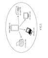
- FIG. 1 is a first view illustrating a case of a 1:N mode in a Wi-Fi direct communication system according to an exemplary embodiment of the present invention.
- a group generated when Wi-Fi devices are connected to each other using the Wi-Fi P2P communication system is referred to as a P2P group.
- one device 110 operates as a group owner and the rest of the peer or counterpart devices 120, 122, 124, and 126 operate as clients or devices.
- the group owner 110 performs a function in a manner similar to an access point of a wireless LAN network in the prior art, and the clients 120, 122, 124, and 126 serve as stations of the wireless LAN network, so that an operation similar to a legacy Wi-Fi system in the prior art is performed.
- a device in each P2P group of the present invention, is not determined in advance to be a client as in the legacy Wi-Fi system of the prior art, but is dynamically determined to be a client via a protocol of group owner negotiation during a Wi-Fi P2P connection process.
- a P2P group using the Wi-Fi direct technology can provide a 1:N connection as well as a 1:1 connection as shown in FIG. 1 , and the number of acceptable clients is determined depending on capability of the group owner 110.
- the 1:N connection is an important advantage of the Wi-Fi direct technology distinguishing the present invention from the P2P technology of the prior art.
- Wi-Fi direct discovery technology according to the teachings of the present invention is described below.
- a process for detecting the existence of a counterpart device is first performed in the present invention.
- a basic P2P discovery process according to the present invention also uses an exchange of Probe Request and Probe Response messages.
- a Wi-Fi P2P device when determining the existence of a desired counterpart device via the above-described P2P discovery process, a Wi-Fi P2P device first performs a Provision Discovery Exchange process with a connection-desired counterpart device.
- the Provision Discovery Exchange process is one of the important characteristics prescribed in a Wi-Fi P2P standard.
- the Wi-Fi P2P device transmits a desired type of WSC configuration method to a connection-desired counterpart device via a Provision Discovery Request message, and the counterpart device that has received the message requests a user's trigger, input, or selection via a popup window on a user interface, an input menu, etc.
- the popup window includes information such as a device name of the device that has requested Provision Discovery, so that the user of the requested counterpart device determines whether to accept a connection and activates WSC.
- a WSC configuration method used for Provision Discovery Exchange includes at least one of a Push Button Configuration (PBC) method, a Personal Identification Number (PIN) from Display method, and PIN from Keypad method.
- PBC Push Button Configuration
- PIN Personal Identification Number
- Keypad method PIN from Keypad method.
- a counterpart device requested via the PIN from Display method displays a WSC PIN window or message to request a user to perform a trigger event.
- a counterpart device requested via the PIN from Keypad method displays a window or message that allows a user to input a PIN, thereby requesting the user to perform a trigger event.
- an access point is not required by the present invention in the connection between the Wi-Fi direct devices, a process for determining a device that will serve as the access point is dynamically performed.
- a group owner negotiation process is completed by exchange of GO Negotiation Request/Response and Confirm messages.
- both devices compare group owner intent values designated by the respective devices, and a device that has designated a larger value performs the role of a group owner. Further, an attribute of a P2P group, an operating channel, listening timing, etc. generated after connection are determined via this process.
- the intent value denotes a degree of a group owner.
- a provisioning process is described below.
- a group owner device operates as a WSC registrar
- a client device operates as a WSC Enrollee, so that the provisioning process for devices exchanging credentials with each other is performed.
- a group formation process for allowing two devices to form a P2P group ends.
- the group owner moves to an actual operation channel to start operating in the role as a group owner, and a group client accesses the group owner using a credential determined via the provisioning process, so that a connection between the two Wi-Fi P2P devices is finally formed.
- both devices determine whether to form a persistent group or a temporary group.
- both P2P devices automatically store credentials (authentication type, encryption type, network key, SSID) and store their determined role in the persistent group.
- devices storing the credentials omit processes such as provision discovery exchange, group owner negotiation, provisioning, etc. and immediately generate a group to raise a connection speed.
- connection-desired device among devices discovered during the discovery process (provision discovery exchange), is a device designated as a member of a persistent group previously
- provision discovery exchange a device designated as a member of a persistent group previously
- the group owner device does not perform the above-described connection process but immediately generates a group through an invitation request/response message exchange including an attribute of a previous group, and a client accesses the generated group via an immediately stored credential, so that a connection speed may be raised.
- the Wi-Fi direct communication standard prescribes a function for connecting a P2P device to be newly connected to the existing group.
- a device already belonging to a P2P group retrieves a connection-desired P2P device via the discovery process, and invites the connection-desired P2P device via an invitation request message including an ID of a current group and attribute information.
- the invited P2P device transmits an invitation response message.
- the P2P group device accepts the invitation response message
- the connection-desired P2P device connects to the group owner of the invited group.
- the invitation request message may be transmitted regardless of the group owner and the group client of the relevant group.
- Wi-Fi P2P group in the 1:N mode is described below.
- One of great characteristics of the Wi-Fi direct technology that is distinguished from other short distance P2P technologies in the prior art is that the Wi-Fi direct technology can generate a group in the 1:N mode around a group owner.
- N+1 P2P devices may share one network to communicate with one another.
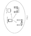
- FIG. 2 is a second view illustrating the case of a 1:N mode in a Wi-Fi direct communication system according to the exemplary embodiment of the present invention.
- the P2P group owner 210 transmits the user's contents to the P2P clients 220, 222, 224 such as a TV and/or an audio device to reproduce the transmitted contents.
- FIG. 3 is a third view illustrating the case of a 1:N mode in a Wi-Fi direct communication system according to the exemplary embodiment of the present invention.
- a P2P group owner 310, P2P clients 320, 322, 324, 326 and an access point 330 exist, and the P2P group owner 310 connects to the devices 320, 322, 324, 326 such as a printer, a PC, an electronic dictionary, etc. usable at an office and uses such devices 320, 322, 324, 326.
- the device 310 of the user may perform concurrent operations of serving as the group owner of the P2P group and connecting to the access point 330 using a Wi-Fi interface.
- FIG. 4 is a fourth view illustrating the case of a 1:N mode in a Wi-Fi direct communication system according to the exemplary embodiment of the present invention.
- a P2P group owner 410 and P2P clients 420, 422 exist and a P2P group may be generated with shooting or image capture equipment such as a camera, a camcorder, etc., and such P2P clients 420, 422 are used by the group owner 410.
- FIG. 5 is a fifth view illustrating the case of a 1:N mode in a Wi-Fi direct communication system according to the exemplary embodiment of the present invention.
- a P2P group owner 510 and P2P clients 520, 522, 524, 526 exist and a user's device 520 serves as a client, not a group owner, and participates in a specific application group to generate a group.
- FIGS. 1-5 illustrate only examples of a small portion of available 1:N groups, and group generation with various P2P devices may be possible depending on the purpose of a user's application to interface with clients having specific functionality, such as a printer or an audio device.
- the Wi-Fi direct communication system is applicable to numerous types of known electronic devices such as a TV, a monitor, an audio, a refrigerator, a printer, a desktop computer, a camera, a camcorder, a projector, etc. as well as mobile devices such as a mobile phone, a notebook computer, a tablet PC, etc.
- a user when desiring to reuse a currently connected P2P group, a user may designate an arbitrary name as a name of a favorite P2P device group.
- the user may select only a relevant device and designate the device as a favorite P2P device group together with an arbitrary name.
- the user's device When the favorite P2P device group is designated, the user's device profiles and stores a list of the device as profile information, with the device designated as the favorite P2P group and a current operation mode of the user's device, and credential information of a current group.
- a matching-desired application may be connected.
- the present invention may regenerate a matched favorite P2P device group automatically when a designated specific application restarts.
- a user does not need to retrieve the same P2P devices of a frequently used P2P group, and does not need to connect to the P2P devices in the P2P group one by one, although the same application and the same P2P group are used every time, so that the user's convenience improves.
- FIG. 6 is a block diagram illustrating a device such as an electronic device according to the exemplary embodiment of the present invention.
- the electronic device 600 may be a portable electronic device, a portable terminal, a mobile phone, a mobile pad, a media player, a tablet computer, a handheld computer, or a Personal Digital Assistant (PDA). Also, the electronic device 600 may be an arbitrary portable electronic device including a device combining two or more functions of these devices.
- PDA Personal Digital Assistant
- the electronic device 600 includes a memory 610, a processor unit 620, a first wireless communication subsystem 630, a second wireless communication subsystem 631, an external port 660, an audio subsystem 650, a speaker 651, a microphone 652, an Input/Output (I/O) system 670, a touchscreen 680, and a different input/control unit 690.
- a plurality of memories 610 and external ports 660 may be used.
- the processor unit 620 may include a memory interface 621, one or more processors 622, and a peripheral interface 623.
- the entire processor unit 620 may be referred to herein as a processor.
- the memory interface 621, one or more processors 622, and/or the peripheral interface 623 may be separate elements or may be integrated in one or more integrated circuits.
- the processor 622 executes various software programs to perform various functions for the electronic device 600, and performs processes and controls for voice communication and data communication. Also, in addition to these general functions, the processor 622 executes a specific software module (instruction set) stored in the memory 610 to perform various specific functions corresponding to each specific software module. That is, the processor 622 performs a method according to the exemplary embodiment of the present invention in cooperation with software modules stored in the memory 610.
- the processor 622 may include one or more data processors, image processors, or a CODEC.
- the data processor, the image processor, or the CODEC may be separately configured.
- the processor 622 may be configured using a plurality of processors performing different functions.
- the peripheral interface 623 connects the I/O subsystem 670 of the electronic device 600 and various peripheral devices to the processor 621, and the memory 610 (via the memory interface 621).
- Various elements of the electronic device 600 may be coupled by one or more communication or data stream lines or communication paths using components and methods known in the art.
- the external port 660 may directly connect the electronic device 600 to a different electronic device, or may be used for indirectly connecting the electronic device 600 to a different electronic device via a network (for example, the Internet, an Intranet, a wireless LAN, etc.).
- a network for example, the Internet, an Intranet, a wireless LAN, etc.
- the external port 660 may be implemented as a Universal Serial Bus (USB) or a port complying with the IEEE 1394 interface standard for a serial bus interface such as a FIREWIRE port commercially available from APPLE CORPORATION, etc. although not limited thereto.
- USB Universal Serial Bus
- FIREWIRE port commercially available from APPLE CORPORATION
- a movement sensor 691 and a first light sensor 692 may be coupled to the peripheral interface 623 to enable various functions.
- the movement sensor 691 and the light sensor 692 may be coupled to the peripheral interface 623 to enable detection of movement of the electronic device 600 and detection of light from outside the electronic device 600.
- other sensors such as a position measurement system, a temperature sensor, or a human body sensor, etc. may be connected to the peripheral interface 623 to perform related functions.
- the camera subsystem 693 may be coupled to a second light sensor 694 to perform a camera function such as shooting, image capture, and video clip recording.
- the first light sensor 692 and the second light sensor 694 may be a charged coupled device (CCD) or a complementary metal-oxide semiconductor (CMOS) device.
- CCD charged coupled device
- CMOS complementary metal-oxide semiconductor
- the electronic device 600 performs a communication function via one or more wireless communication subsystems 630, 631.
- the wireless communication subsystems 630, 631 may include a Radio Frequency (RF) receiver and transceiver and/or a light (for example, infrared) receiver and transceiver.
- RF Radio Frequency
- the first communication subsystem 630 and the second communication subsystem 631 may be classified depending on a communication network with which the electronic device 600 communicates.
- the communication network may include a communication subsystem designed for operating via a Global System for Mobile Communication (GSM) network, an Enhanced Data GSM Environment (EDGE) network, a Code Division Multiple Access (CDMA) network, a W-Code Division Multiple Access (W-CDMA) network, a Long Term Evolution (LTE) network, an Orthogonal Frequency Division Multiple Access (OFDMA) network, a Wireless Fidelity (Wi-Fi) network, a WiMax network, and/or a BLUETOOTH network, etc.
- GSM Global System for Mobile Communication
- EDGE Enhanced Data GSM Environment
- CDMA Code Division Multiple Access
- W-CDMA W-Code Division Multiple Access
- LTE Long Term Evolution
- OFDMA Orthogonal Frequency Division Multiple Access
- Wi-Fi Wireless Fidelity
- WiMax WiMax
- BLUETOOTH a BLUETOOTH network
- one of the first wireless communication subsystem 630 and the second wireless communication subsystem 631 may be a Wi-Fi direct communication subsystem.
- the first wireless communication subsystem 630 and the second wireless communication subsystem 631 may be merged to form one wireless communication subsystem.
- the audio subsystem 650 may be coupled to the speaker 651 and the microphone 652 to provide functions of voice recognition, voice duplication, digital recording, and input and output of an audio stream such as a telephone function.
- the audio subsystem 650 communicates with a user using audio via the speaker 651 and the microphone 652.
- the audio subsystem 650 receives a data stream via the peripheral interface 623 of the processor unit 620 and converts the received data stream to an electric stream, such as one or more electrical currents or signals.
- the converted electric stream (electric signal) is transferred to the speaker 651.
- the speaker 651 converts the electric stream to a sound wave that can be heard by a human being and outputs the sound wave.
- the microphone 652 converts a sound wave transferred from a human being or other sound sources to an electric stream.
- the audio subsystem 650 receives the electric stream converted from the microphone 652.
- the audio subsystem 650 converts the received electric stream to an audio data stream and transmits the converted audio data stream to the peripheral interface 623.
- the audio subsystem 650 may include an attachable and detachable ear phone, a head phone, or a head set.
- the I/O subsystem 670 may include a touchscreen controller 671 and/or a different input controller 672.
- the touchscreen controller 671 may be coupled to the touchscreen 680.
- the touchscreen 680 and the touchscreen controller 671 may detect a contact and movement or stoppage of these using an arbitrary multi-touch detection technology including other proximity sensor arrangements or other elements as well as capacitive, resistive, infrared, and surface acoustic wave technologies for determining one or more contact points with the touchscreen 680 although not limited thereto.
- the different input controller 672 may be coupled to the different input/control unit 690.
- the different input/control unit 690 may include one or more buttons such as up/down buttons for controlling a volume. Also, the buttons may be a push button or a rocker button, a rocker switch, a thumb-wheel, a dial, a stick, and/or a pointer device such as a stylus, etc.
- the touchscreen 680 provides an input/output interface between the electronic device 600 and a user. That is, the touchscreen 680 transfers the user's touch input to the electronic device 600. Also, the touchscreen 680 serves as a medium for showing an output of the electronic device 600 to the user.
- the touchscreen 680 shows a visual output to the user.
- This visual output appears in the form of text, graphics, video, and a combination of such visual outputs.
- the touchscreen 680 may be a Liquid Crystal Display (LCD), a Light Emitting Diode (LED), a Light Emitting Polymer Display (LPD), an Organic Light Emitting Diode (OLED), an Active Matrix Organic Light Emitting Diode (AMOLED) or a Flexible LED (FLED).
- LCD Liquid Crystal Display
- LED Light Emitting Diode
- LPD Light Emitting Polymer Display
- OLED Organic Light Emitting Diode
- AMOLED Active Matrix Organic Light Emitting Diode
- FLED Flexible LED
- the memory 610 may be coupled to the memory interface 621.
- the memory 610 may include a high speed random access memory such as one or more magnetic disc storage devices and/or a non-volatile memory, one or more optical storage devices and/or a flash memory (for example, NAND, NOR).
- the memory 610 stores data and information, such as the profile information, as well as software, which may be applications or other forms of software, including software elements.
- Software elements include an operating system module 611, a communication module 612, a graphic module 613, a user interface module 614, a CODEC module 615, a camera module 616, and one or more application modules 617, etc.
- the application module 617 includes a Wi-Fi application for controlling a Wi-Fi direct communication system implemented by the present invention. Also, since each module 611-617, which is a software element, can be expressed in terms of a set of instructions, the modules 611-617 may also be expressed as an instruction set. The module may also be expressed as a program. According to the present invention, one or more modules including instructions for performing various methods of the present invention may be stored in the memory 610.
- the operating system software 611 (for example, a built-in operating system such as WINDOWS, LINUX, Darwin, RTXC, UNIX, OS X, or VxWorks) includes various software elements for controlling a general system operation.
- control of the general system operation may include memory management and control, storage hardware (device) control and management, power control and management, etc.
- This operating system software 611 performs a function for smoothing communication between various hardware (devices) and software elements (modules).
- the communication module 612 may enable communication with other electronic devices such as a computer, a server and/or a portable terminal, etc. via the wireless communication subsystem 630, 631 or the external port 660.
- the graphic module 613 includes various software elements for providing and displaying graphics on the touchscreen 680.
- the graphics may include text, a web page, an icon, a digital image, a video, animation, etc.
- the user interface module 614 includes various software elements related to a user interface.
- the user interface module 614 includes content as to how the state of the user interface is changed or under what condition a change of a user interface state is performed, etc.
- the CODEC module 615 may include software elements related to encoding and decoding of a video file.
- the CODEC module may include an MPEG module and/or a video stream module such as an H204 module.
- the CODEC module 615 may include a CODEC module for various audio files in known audio formats such as AAA, Adaptive Multi-Rate (AMR), WINDOWS Media Audio (WMA), etc.
- the camera module 616 includes camera-related software elements for enabling camera-related processes and functions.
- the application module 617 includes a browser, electronic mail, an instant message, word processing, keyboard emulation, an address book, a touch list, a widget, Digital Right Management (DRM), voice recognition, voice duplication, position determining function, location based service, etc.
- DRM Digital Right Management
- the memory 610 may include an additional module (instructions) besides the above-described modules. Alternatively, the memory 610 may not use some of the modules (instructions) when not needed.
- various functions of the electronic device 600 according to the present invention mentioned above or to be mentioned below may be executed by hardware including one or more stream or data processors and/or one or more Application Specific Integrated Circuits (ASIC) and/or a software and/or a combination of such hardware and software.
- ASIC Application Specific Integrated Circuit
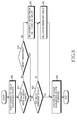
- FIG. 7 is a first flowchart illustrating an operation process of the electronic device according to the exemplary embodiment of the present invention.
- a user of a Wi-Fi direct communication electronic device belongs to a 1:N mode P2P group and uses the same, and then designates a favorite P2P group for the purpose of reuse.
- the user may select a desired device from a device list of a currently formed P2P group in step 705. However, if no device is selected, the method loops back to step 705 until a device is selected.
- the user designates a name of the current favorite P2P group using a familiar name favored by the user in step 710. However, if no name is designated, the method loops back to step 710 until a name is designated.
- the user may selectively designate the specific application in step 715. However, if no application is designated, the method loops back to step 715 until an application is designated. Thus, when the designated application starts later, the favorite P2P group is automatically regenerated by the electronic device 600.
- the electronic device 600 redefines an attribute so that a list of devices belonging to the currently designated favorite P2P group is easily regenerated afterward and performs an update of the redefined favorite P2P group as a background operation.
- the electronic device 600 stores a list of devices input by the user, an operation mode of the device of the electronic device and an operation mode of a counterpart device in step 720, and the method in FIG. 7 ends.
- the operation mode of the electronic device 600 indicates whether or not the electronic device 600 is to function as a group owner or not.
- profile information regarding a device retrieved from the P2P group that is, a device list and an operation mode of a relevant device, an operation mode of the electronic device, a credential of a P2P group, an access point credential, a P2P group name, and a profile number for the name may be stored.
- the electronic device 600 stores an access credential (SSID, security info) of an access point and stores a credential (group ID, security info) of a current favorite P2P group.
- the electronic device 600 stores application information connected to the favorite P2P group and designates a profile number so that the stored information matches with a familiar name input by the user.
- the method described above in relation with FIG. 7 under of the present invention may be provided as one or more instructions in one or more software modules, or computer programs stored in an electronic device.
- FIG. 8 is a second flowchart illustrating an operation process of the electronic device according to the exemplary embodiment of the present invention.
- a background update process is illustrated, which is performed while the method of FIG. 7 is performed.
- the background update process of a favorite P2P group starts in step 805
- an operation mode of the electronic device 600 in the currently used P2P group is determined in step 810.
- the method proceeds to step 815.
- existence of a P2P group owner is indispensably required.
- step 810 in the case where the operation mode of the electronic device is a group owner mode as determined in step 810, whether the currently generated group is a persistent group is determined in step 820. However, if no persistent group is found, the method proceeds to step 835.
- step 820 when the currently generated group is the persistent group, the background update process of the favorite P2P group is completed in step 830 and the method of FIG. 8 ends.
- profile information regarding a device retrieved from the P2P group that is, a device list and an operation mode of a relevant device, an operation mode of the electronic device 600, a credential of a P2P group, an access point credential, a P2P group name, and a profile number for the name may be stored.
- the generated persistent group is one of P2P groups and the generated persistent group is not temporary.
- the relevant electronic device may omit a Provision Discovery Exchange, a Group Owner Negotiation Exchange, and a Provisioning process afterward by storing a credential and an operation mode of a current P2P group, so that a connection process may be reduced.
- the present invention is intended for maximizing usability of the present invention by allowing regeneration of a favorite P2P group to be based on a persistent group attribute of the Wi-Fi direct communication standard.
- step 820 in the case where the P2P group is not the persistent group determined in step 820, a process for changing an attribute of a group to an attribute of the persistent group is performed in step 835, and the method proceeds to step 830.
- a Group Owner Negotiation Exchange and Provisioning processes are performed to establish a relation of the persistent group with all devices of a selected device list one by one.
- the present invention makes possible a quick changing of an attribute of a group to an attribute of the persistent group without reconnection by making a maximum use of an attribute of the current group, and a connection process including Group Owner Negotiation Exchange may be performed again, but such a repeat of the connection process including Group Owner Negotiation Exchange may take much time when there are many devices.
- the above processes may be performed using various application methods.
- a favorite P2P group which is currently already selected, has an attribute of the persistent group, all selected devices store a credential of the current group, group owner device information, etc. to update the persistent group again. After that, the P2P group background update process is completed in step 830.
- step 810 in the case where an operation mode of the electronic device is not the group owner mode in step 810 but a group owner already exists in step 815, a process for determining whether a generated group is the persistent group in step 820 and subsequent processes are performed.
- step 815 when the group owner does not exist, an automatic group owner generation process is performed in step 825, and the method proceeds to step 835.
- a process for setting the electronic device 600 to an automatic group owner, and designating the group as the persistent group to change an attribute of the group to an attribute of the persistent group is performed in step 825.
- the process for setting the electronic device 600 to the automatic group owner may be performed in step 825 or step 835.
- step 825 the persistent group is regenerated using the selected devices via an invitation process, and the persistent group updated step 835.
- the above-described credential storing process may be performed.
- the method described above in relation with FIG. 8 under of the present invention may be provided as one or more instructions in one or more software modules, or computer programs stored in an electronic device.
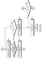
- FIGS. 9A and 9B are a third flowchart illustrating the operation process of the electronic device according to the exemplary embodiment of the present invention.
- FIGS. 9A and 9B a process for regenerating a favorite P2P group profile is illustrated.
- a user may select a specific familiar name set as a favorite P2P group from a favorite P2P group list, or when a linked application exists, may start the favorite P2P group by executing the relevant application in step 910.
- the electronic device 600 finds a profile number matching with a familiar name on a stored profile list for a favorite P2P group, and obtains stored profile information corresponding to the found profile in step 915. The method then proceeds to step 917.
- step 917 In the case where access point information exists on the stored device list as determined in step 917, the relevant access point is scanned and connected via a credential of a stored access point in step 919, and the method proceeds to step 920. However, in step 917, if an access point does not exist, the method proceeds directly to step 920. When SCAN and connection processes are not performed, a user may be informed of such non-performance, for example, by an outputted message.
- the stored P2P group sets the electronic device 600 to an automatic group owner in step 930. Otherwise, if the electronic device 600 is not a group owner, the method proceeds to step 925 in FIG. 9B .
- step 930 stored device lists are retrieved via a background P2P discovery process in step 945.
- a matched P2P device is discovered in step 960, an invite message is transmitted to the discovered device to generate a persistent group in step 970.
- step 960 if no matched P2P device is discovered, the method proceeds to step 965 in FIG. 9B .
- the background P2P discovery process is checked whether the process is completed in step 980. If the process is not completed, the method proceeds to step 965 in FIG. 9B ; otherwise, the method proceeds to step 985, in which the favorite P2P group regeneration is completed and the method ends.
- step 960 when retrieval and connection of a stored device list are not performed while the favorite P2P group is regenerated in step 960, a retrieval and connection process of a stored device list is continuously performed via the background P2P discovery process in step 945 until time-out arrives in step 965 of FIG. 9B .
- step 965 When the time-out state arrives in step 965, a user is informed of such information and a state regarding a device currently not being connected in step 975, for example, by an outputted message, and the method ends.
- step 920 when the electronic device is not the group owner determine in step 920, the background P2P discovery process is performed first in step 925 and the matched P2P group owner device is checked so that the group owner is retrieved in step 935. If no matched P2P group owner device in step 935 when the time-out arrives in step 940, the method proceeds to step 955. However, if no time-out arrives in step 940, the method loops back to step 925.
- step 935 when the group is retrieved, generation of a persistent group is triggered using stored P2P group credential information in order to invite other devices in step 950. After that, a favorite P2P group background update process in step 945 and subsequent steps are performed for the rest of the devices in the group.
- step 940 when time-out arrives without retrieval in step 940, the favorite P2P group background update process ends in step 955, and the user is informed of information and a state for a currently not connected device in step 975, for example, by an outputted message, and the method ends.
- the present invention provides an advantage of allowing a user to simply recover a favorite P2P device group by simply selecting a device of the favorite P2P group or starting a connected application without reconnecting the device of the favorite P2P group that uses the same application one by one every time.
- the method described above in relation with FIG. 9A and 9B under of the present invention may be provided as one or more instructions in one or more software modules, or computer programs stored in an electronic device.
- a generation speed of a P2P group may be raised, use convenience of a user of a Wi-Fi direct device may be maximized, and an advantage of a Wi-Fi direct communication system that can configure a 1:N mode group compared to the P2P technology of the prior art may be more efficiently used.
- the above-described apparatus and methods according to the present invention can be implemented in hardware, firmware or as software or computer code that can be stored in a non-transitory recording medium such as a CD ROM, a RAM, a ROM, a floppy disk, DVDs, a hard disk, a magnetic storage media, an optical recording media, or a magneto-optical disk or computer code downloaded over a network originally stored on a remote recording medium, a computer readable recording medium, or a non-transitory machine readable medium and to be stored on a local recording medium, so that the methods described herein can be rendered in such software that is stored on the recording medium using a general purpose computer, a digital computer, or a special processor or in programmable or dedicated hardware, such as an ASIC or FPGA.
- a non-transitory recording medium such as a CD ROM, a RAM, a ROM, a floppy disk, DVDs, a hard disk, a magnetic storage media, an optical recording media, or a magneto
- the computer, the processor, microprocessor controller or the programmable hardware include memory components, e.g., RAM, ROM, Flash, etc. that may store or receive software or computer code that when accessed and executed by the computer, processor or hardware implement the processing methods described herein.
- memory components e.g., RAM, ROM, Flash, etc.
- the execution of the code transforms the general purpose computer into a special purpose computer for executing the processing shown herein.
- the program may be electronically transferred through any media such as communication signals transmitted by wire/wireless connections, and their equivalents.
Applications Claiming Priority (1)
| Application Number | Priority Date | Filing Date | Title |
|---|---|---|---|
| KR1020120026597A KR101842047B1 (ko) | 2012-03-15 | 2012-03-15 | 와이 파이 다이렉트 통신 시스템에서 그룹 프로파일 관리를 위한 방법 및 장치 |
Publications (3)
| Publication Number | Publication Date |
|---|---|
| EP2677774A2 true EP2677774A2 (de) | 2013-12-25 |
| EP2677774A3 EP2677774A3 (de) | 2014-07-23 |
| EP2677774B1 EP2677774B1 (de) | 2020-05-06 |
Family
ID=47779933
Family Applications (1)
| Application Number | Title | Priority Date | Filing Date |
|---|---|---|---|
| EP13157304.0A Active EP2677774B1 (de) | 2012-03-15 | 2013-02-28 | Verfahren und Vorrichtung zur Verwaltung eines Gruppenprofils in einem Wi-Fi-Direktkommunikationssystems |
Country Status (5)
| Country | Link |
|---|---|
| US (2) | US9100801B2 (de) |
| EP (1) | EP2677774B1 (de) |
| KR (1) | KR101842047B1 (de) |
| CN (1) | CN103312534B (de) |
| ES (1) | ES2804453T3 (de) |
Families Citing this family (26)
| Publication number | Priority date | Publication date | Assignee | Title |
|---|---|---|---|---|
| KR101961799B1 (ko) * | 2012-11-06 | 2019-03-25 | 에이치피프린팅코리아 유한회사 | 근거리 무선 통신 기능을 지원하는 화상형성장치 및 화상형성장치에서 메뉴를 표시하는 방법 |
| CN104813735B (zh) * | 2013-03-12 | 2018-11-23 | Lg电子株式会社 | 在直接通信系统中用于对等组形成的方法及其装置 |
| US10314084B2 (en) * | 2013-07-09 | 2019-06-04 | Nec Corporation | Communication terminal |
| EP3028526B1 (de) * | 2013-08-04 | 2019-04-10 | LG Electronics Inc. | Verfahren und vorrichtung für den start einer vorrichtung-zu-vorrichtung-operation in einem drahtloskommunikationssystem |
| AU2014344788A1 (en) * | 2013-10-29 | 2016-05-26 | Kortek Industries Pty Ltd | Adaptable multi-mode wireless power, light and automation |
| US9652195B2 (en) | 2013-11-22 | 2017-05-16 | Qualcomm Incorporated | Audio output device that utilizes policies to concurrently handle multiple audio streams from different source devices |
| WO2015098003A1 (ja) | 2013-12-26 | 2015-07-02 | 日本電気株式会社 | 通信端末の接続制御方法 |
| US10250698B2 (en) * | 2014-08-25 | 2019-04-02 | Futurewei Technologies, Inc. | System and method for securing pre-association service discovery |
| KR102208438B1 (ko) * | 2014-11-26 | 2021-01-27 | 삼성전자주식회사 | 근접 서비스 데이터 송신 방법 및 그 전자 장치 |
| US10362452B2 (en) | 2014-11-26 | 2019-07-23 | Nec Corporation | Mechanism for quick connection in wireless peer to peer networks |
| US9544755B2 (en) * | 2015-01-30 | 2017-01-10 | Nokia Technologies Oy | Method, apparatus, and computer program product for non-scannable device discovery |
| CN110602223B (zh) * | 2015-06-15 | 2021-10-15 | 展讯通信(上海)有限公司 | 点对点设备及其搜索匹配方法 |
| CN104936258A (zh) * | 2015-06-17 | 2015-09-23 | 青岛海信移动通信技术股份有限公司 | 网络连接方法、终端及系统 |
| JP6312842B2 (ja) | 2015-08-14 | 2018-04-18 | エスゼット ディージェイアイ テクノロジー カンパニー リミテッドSz Dji Technology Co.,Ltd | 異機種環境においてデータ通信を支援するためのシステム及び方法、並びにプログラム |
| US10264609B2 (en) * | 2015-09-29 | 2019-04-16 | Universiti Brunei Danssalam | Method and system for ad-hoc social networking and profile matching |
| US9756286B1 (en) * | 2016-08-05 | 2017-09-05 | Microsoft Technology Licensing, Llc | Communication event |
| CN107087265A (zh) * | 2017-03-23 | 2017-08-22 | 嘉兴爱尔特云网络科技有限责任公司 | 一种连接多个WiFi‑Direct群组的通信装置及方法 |
| WO2019000229A1 (zh) * | 2017-06-27 | 2019-01-03 | 深圳市大疆创新科技有限公司 | 无线设备的配对方法和装置以及计算设备 |
| KR102366312B1 (ko) | 2017-09-20 | 2022-02-25 | 삼성전자주식회사 | 근거리 통신의 재연결을 수행하는 전자 장치 및 그 동작 방법 |
| KR102373548B1 (ko) * | 2018-02-23 | 2022-03-11 | 삼성전자주식회사 | 근거리 통신 연결을 위한 전자 장치 및 방법 |
| CN108683793B (zh) * | 2018-03-26 | 2020-10-30 | 维沃移动通信有限公司 | 应用图标的显示方法和移动终端 |
| CN110832947B (zh) * | 2018-04-12 | 2021-08-31 | 华为技术有限公司 | 一种组网方法及设备 |
| CN109587667B (zh) * | 2018-11-23 | 2021-06-18 | Oppo广东移动通信有限公司 | 一种连接建立方法及装置、设备、存储介质 |
| CN110213017B (zh) * | 2019-04-30 | 2021-11-12 | 普联技术有限公司 | 一种数据传输方法、装置、系统、存储介质及终端设备 |
| US11159610B2 (en) * | 2019-10-10 | 2021-10-26 | Dell Products, L.P. | Cluster formation offload using remote access controller group manager |
| CN115643542B (zh) * | 2022-11-29 | 2023-05-16 | 荣耀终端有限公司 | 一种无线投屏方法、电子设备及计算机可读存储介质 |
Family Cites Families (9)
| Publication number | Priority date | Publication date | Assignee | Title |
|---|---|---|---|---|
| US7949581B2 (en) | 2005-09-07 | 2011-05-24 | Patentratings, Llc | Method of determining an obsolescence rate of a technology |
| US20070094279A1 (en) * | 2005-10-21 | 2007-04-26 | Nokia Corporation | Service provision in peer-to-peer networking environment |
| EP2122984B1 (de) | 2007-02-19 | 2021-01-13 | Telefonaktiebolaget LM Ericsson (publ) | Verfahren und vorrichtung zur aktivierung von benutzergruppendiensten in einem kommunikationsnetz |
| CN101594578B (zh) * | 2008-05-30 | 2013-08-28 | 华为终端有限公司 | 直连链路的建立方法、站设备及通信系统 |
| US8559340B2 (en) | 2009-12-22 | 2013-10-15 | Samsung Electronics Co., Ltd. | Method and apparatus for service discovery in Wi-Fi direct network |
| JP5343841B2 (ja) * | 2009-12-22 | 2013-11-13 | ソニー株式会社 | 無線通信装置、無線通信方法、プログラム、および無線通信システム |
| KR101700937B1 (ko) | 2009-12-22 | 2017-01-31 | 삼성전자주식회사 | WiFi Direct 네트워크에서의 서비스 탐색 방법 및 장치 |
| US8493992B2 (en) | 2010-02-04 | 2013-07-23 | Texas Instruments Incorporated | Interrelated WiFi and USB protocols and other application framework processes, circuits and systems |
| JP5598081B2 (ja) * | 2010-05-17 | 2014-10-01 | ソニー株式会社 | 無線通信装置、無線通信方法、プログラム、および無線通信システム |
-
2012
- 2012-03-15 KR KR1020120026597A patent/KR101842047B1/ko active IP Right Grant
-
2013
- 2013-02-27 US US13/778,874 patent/US9100801B2/en active Active
- 2013-02-28 EP EP13157304.0A patent/EP2677774B1/de active Active
- 2013-02-28 ES ES13157304T patent/ES2804453T3/es active Active
- 2013-03-14 CN CN201310081151.XA patent/CN103312534B/zh active Active
-
2015
- 2015-07-24 US US14/808,020 patent/US9510163B2/en active Active
Non-Patent Citations (1)
| Title |
|---|
| None |
Also Published As
| Publication number | Publication date |
|---|---|
| KR101842047B1 (ko) | 2018-03-26 |
| US9100801B2 (en) | 2015-08-04 |
| KR20130104768A (ko) | 2013-09-25 |
| CN103312534A (zh) | 2013-09-18 |
| US9510163B2 (en) | 2016-11-29 |
| CN103312534B (zh) | 2018-01-09 |
| US20130242805A1 (en) | 2013-09-19 |
| EP2677774A3 (de) | 2014-07-23 |
| ES2804453T3 (es) | 2021-02-08 |
| EP2677774B1 (de) | 2020-05-06 |
| US20150334538A1 (en) | 2015-11-19 |
Similar Documents
| Publication | Publication Date | Title |
|---|---|---|
| US9510163B2 (en) | Method and apparatus for managing a group profile in a Wi-Fi direct communication system | |
| WO2017140276A1 (zh) | 网络连接方法及装置、计算机存储介质 | |
| JP6009524B2 (ja) | モバイルデバイスのための外部タッチスクリーン | |
| US9258841B2 (en) | Method of reducing a waiting time when cancelling a connection and an electronic device therefor | |
| JP6228676B2 (ja) | 接続状態プロンプティング方法および装置 | |
| WO2017185711A1 (zh) | 控制智能设备的方法、装置、系统和存储介质 | |
| CN108040091B (zh) | 数据处理方法、装置及存储介质 | |
| TWI512525B (zh) | 關聯終端的方法及系統、終端及電腦可讀取儲存介質 | |
| US20160162240A1 (en) | Method and apparatus for constructing multi-screen display | |
| KR102249413B1 (ko) | 이미지 공유 방법 및 전자 디바이스 | |
| US20140059652A1 (en) | Apparatus for uploading contents, user terminal apparatus for downloading contents, server, contents sharing system and their contents sharing method | |
| WO2015014144A1 (zh) | 一种安装应用的方法、装置和终端设备 | |
| EP3487201B1 (de) | Elektronische vorrichtung zur steuerung einer externen vorrichtung mit einer zahl und verfahren dafür | |
| CN104853336A (zh) | 发现智能设备的方法、请求接入互联网的方法及装置 | |
| KR102294040B1 (ko) | 데이터 송수신 방법 및 장치 | |
| US20150379322A1 (en) | Method and apparatus for communication using fingerprint input | |
| CN108605373B (zh) | 用于提供网络共享服务的方法和电子装置 | |
| CN104158854B (zh) | 资源共享方法及装置 | |
| US11323880B2 (en) | Method for wireless connection and electronic device therefor | |
| WO2019057119A1 (zh) | 基于移动终端的wifi热点连接方法及移动终端、存储介质 | |
| WO2015062506A1 (zh) | 多图标选择方法与终端 | |
| CN110832947B (zh) | 一种组网方法及设备 | |
| JP6900546B2 (ja) | 画像共有方法および電子デバイス | |
| CN110582079A (zh) | 一种蓝牙连接设置方法、装置、计算机可读存储介质及终端 | |
| CN105407518A (zh) | 设备联网方法及装置 |
Legal Events
| Date | Code | Title | Description |
|---|---|---|---|
| PUAI | Public reference made under article 153(3) epc to a published international application that has entered the european phase |
Free format text: ORIGINAL CODE: 0009012 |
|
| AK | Designated contracting states |
Kind code of ref document: A2 Designated state(s): AL AT BE BG CH CY CZ DE DK EE ES FI FR GB GR HR HU IE IS IT LI LT LU LV MC MK MT NL NO PL PT RO RS SE SI SK SM TR |
|
| AX | Request for extension of the european patent |
Extension state: BA ME |
|
| PUAL | Search report despatched |
Free format text: ORIGINAL CODE: 0009013 |
|
| AK | Designated contracting states |
Kind code of ref document: A3 Designated state(s): AL AT BE BG CH CY CZ DE DK EE ES FI FR GB GR HR HU IE IS IT LI LT LU LV MC MK MT NL NO PL PT RO RS SE SI SK SM TR |
|
| AX | Request for extension of the european patent |
Extension state: BA ME |
|
| RIC1 | Information provided on ipc code assigned before grant |
Ipc: H04W 84/20 20090101ALI20140617BHEP Ipc: H04W 76/02 20090101ALI20140617BHEP Ipc: H04W 4/08 20090101AFI20140617BHEP Ipc: H04L 12/28 20060101ALI20140617BHEP Ipc: H04L 29/08 20060101ALI20140617BHEP Ipc: H04W 8/00 20090101ALN20140617BHEP Ipc: H04W 4/00 20090101ALI20140617BHEP |
|
| 17P | Request for examination filed |
Effective date: 20150122 |
|
| STAA | Information on the status of an ep patent application or granted ep patent |
Free format text: STATUS: EXAMINATION IS IN PROGRESS |
|
| 17Q | First examination report despatched |
Effective date: 20181012 |
|
| REG | Reference to a national code |
Ref country code: DE Ref legal event code: R079 Ref document number: 602013068638 Country of ref document: DE Free format text: PREVIOUS MAIN CLASS: H04W0004000000 Ipc: H04W0004080000 |
|
| GRAP | Despatch of communication of intention to grant a patent |
Free format text: ORIGINAL CODE: EPIDOSNIGR1 |
|
| STAA | Information on the status of an ep patent application or granted ep patent |
Free format text: STATUS: GRANT OF PATENT IS INTENDED |
|
| RIC1 | Information provided on ipc code assigned before grant |
Ipc: H04W 4/00 20180101ALI20200121BHEP Ipc: H04W 4/08 20090101AFI20200121BHEP Ipc: H04W 4/50 20180101ALI20200121BHEP Ipc: H04W 8/00 20090101ALN20200121BHEP Ipc: H04L 12/28 20060101ALI20200121BHEP Ipc: H04L 29/08 20060101ALI20200121BHEP Ipc: H04W 84/20 20090101ALI20200121BHEP |
|
| INTG | Intention to grant announced |
Effective date: 20200207 |
|
| GRAS | Grant fee paid |
Free format text: ORIGINAL CODE: EPIDOSNIGR3 |
|
| GRAA | (expected) grant |
Free format text: ORIGINAL CODE: 0009210 |
|
| STAA | Information on the status of an ep patent application or granted ep patent |
Free format text: STATUS: THE PATENT HAS BEEN GRANTED |
|
| AK | Designated contracting states |
Kind code of ref document: B1 Designated state(s): AL AT BE BG CH CY CZ DE DK EE ES FI FR GB GR HR HU IE IS IT LI LT LU LV MC MK MT NL NO PL PT RO RS SE SI SK SM TR |
|
| REG | Reference to a national code |
Ref country code: GB Ref legal event code: FG4D |
|
| REG | Reference to a national code |
Ref country code: AT Ref legal event code: REF Ref document number: 1268790 Country of ref document: AT Kind code of ref document: T Effective date: 20200515 Ref country code: CH Ref legal event code: EP |
|
| REG | Reference to a national code |
Ref country code: IE Ref legal event code: FG4D |
|
| REG | Reference to a national code |
Ref country code: DE Ref legal event code: R096 Ref document number: 602013068638 Country of ref document: DE |
|
| REG | Reference to a national code |
Ref country code: NL Ref legal event code: FP |
|
| REG | Reference to a national code |
Ref country code: LT Ref legal event code: MG4D |
|
| PG25 | Lapsed in a contracting state [announced via postgrant information from national office to epo] |
Ref country code: IS Free format text: LAPSE BECAUSE OF FAILURE TO SUBMIT A TRANSLATION OF THE DESCRIPTION OR TO PAY THE FEE WITHIN THE PRESCRIBED TIME-LIMIT Effective date: 20200906 Ref country code: SE Free format text: LAPSE BECAUSE OF FAILURE TO SUBMIT A TRANSLATION OF THE DESCRIPTION OR TO PAY THE FEE WITHIN THE PRESCRIBED TIME-LIMIT Effective date: 20200506 Ref country code: NO Free format text: LAPSE BECAUSE OF FAILURE TO SUBMIT A TRANSLATION OF THE DESCRIPTION OR TO PAY THE FEE WITHIN THE PRESCRIBED TIME-LIMIT Effective date: 20200806 Ref country code: LT Free format text: LAPSE BECAUSE OF FAILURE TO SUBMIT A TRANSLATION OF THE DESCRIPTION OR TO PAY THE FEE WITHIN THE PRESCRIBED TIME-LIMIT Effective date: 20200506 Ref country code: PT Free format text: LAPSE BECAUSE OF FAILURE TO SUBMIT A TRANSLATION OF THE DESCRIPTION OR TO PAY THE FEE WITHIN THE PRESCRIBED TIME-LIMIT Effective date: 20200907 Ref country code: GR Free format text: LAPSE BECAUSE OF FAILURE TO SUBMIT A TRANSLATION OF THE DESCRIPTION OR TO PAY THE FEE WITHIN THE PRESCRIBED TIME-LIMIT Effective date: 20200807 Ref country code: FI Free format text: LAPSE BECAUSE OF FAILURE TO SUBMIT A TRANSLATION OF THE DESCRIPTION OR TO PAY THE FEE WITHIN THE PRESCRIBED TIME-LIMIT Effective date: 20200506 |
|
| PG25 | Lapsed in a contracting state [announced via postgrant information from national office to epo] |
Ref country code: LV Free format text: LAPSE BECAUSE OF FAILURE TO SUBMIT A TRANSLATION OF THE DESCRIPTION OR TO PAY THE FEE WITHIN THE PRESCRIBED TIME-LIMIT Effective date: 20200506 Ref country code: HR Free format text: LAPSE BECAUSE OF FAILURE TO SUBMIT A TRANSLATION OF THE DESCRIPTION OR TO PAY THE FEE WITHIN THE PRESCRIBED TIME-LIMIT Effective date: 20200506 Ref country code: RS Free format text: LAPSE BECAUSE OF FAILURE TO SUBMIT A TRANSLATION OF THE DESCRIPTION OR TO PAY THE FEE WITHIN THE PRESCRIBED TIME-LIMIT Effective date: 20200506 Ref country code: BG Free format text: LAPSE BECAUSE OF FAILURE TO SUBMIT A TRANSLATION OF THE DESCRIPTION OR TO PAY THE FEE WITHIN THE PRESCRIBED TIME-LIMIT Effective date: 20200806 |
|
| REG | Reference to a national code |
Ref country code: AT Ref legal event code: MK05 Ref document number: 1268790 Country of ref document: AT Kind code of ref document: T Effective date: 20200506 |
|
| PG25 | Lapsed in a contracting state [announced via postgrant information from national office to epo] |
Ref country code: AL Free format text: LAPSE BECAUSE OF FAILURE TO SUBMIT A TRANSLATION OF THE DESCRIPTION OR TO PAY THE FEE WITHIN THE PRESCRIBED TIME-LIMIT Effective date: 20200506 |
|
| PG25 | Lapsed in a contracting state [announced via postgrant information from national office to epo] |
Ref country code: IT Free format text: LAPSE BECAUSE OF FAILURE TO SUBMIT A TRANSLATION OF THE DESCRIPTION OR TO PAY THE FEE WITHIN THE PRESCRIBED TIME-LIMIT Effective date: 20200506 Ref country code: SM Free format text: LAPSE BECAUSE OF FAILURE TO SUBMIT A TRANSLATION OF THE DESCRIPTION OR TO PAY THE FEE WITHIN THE PRESCRIBED TIME-LIMIT Effective date: 20200506 Ref country code: RO Free format text: LAPSE BECAUSE OF FAILURE TO SUBMIT A TRANSLATION OF THE DESCRIPTION OR TO PAY THE FEE WITHIN THE PRESCRIBED TIME-LIMIT Effective date: 20200506 Ref country code: CZ Free format text: LAPSE BECAUSE OF FAILURE TO SUBMIT A TRANSLATION OF THE DESCRIPTION OR TO PAY THE FEE WITHIN THE PRESCRIBED TIME-LIMIT Effective date: 20200506 Ref country code: EE Free format text: LAPSE BECAUSE OF FAILURE TO SUBMIT A TRANSLATION OF THE DESCRIPTION OR TO PAY THE FEE WITHIN THE PRESCRIBED TIME-LIMIT Effective date: 20200506 Ref country code: AT Free format text: LAPSE BECAUSE OF FAILURE TO SUBMIT A TRANSLATION OF THE DESCRIPTION OR TO PAY THE FEE WITHIN THE PRESCRIBED TIME-LIMIT Effective date: 20200506 Ref country code: DK Free format text: LAPSE BECAUSE OF FAILURE TO SUBMIT A TRANSLATION OF THE DESCRIPTION OR TO PAY THE FEE WITHIN THE PRESCRIBED TIME-LIMIT Effective date: 20200506 |
|
| REG | Reference to a national code |
Ref country code: ES Ref legal event code: FG2A Ref document number: 2804453 Country of ref document: ES Kind code of ref document: T3 Effective date: 20210208 |
|
| REG | Reference to a national code |
Ref country code: DE Ref legal event code: R097 Ref document number: 602013068638 Country of ref document: DE |
|
| PG25 | Lapsed in a contracting state [announced via postgrant information from national office to epo] |
Ref country code: PL Free format text: LAPSE BECAUSE OF FAILURE TO SUBMIT A TRANSLATION OF THE DESCRIPTION OR TO PAY THE FEE WITHIN THE PRESCRIBED TIME-LIMIT Effective date: 20200506 Ref country code: SK Free format text: LAPSE BECAUSE OF FAILURE TO SUBMIT A TRANSLATION OF THE DESCRIPTION OR TO PAY THE FEE WITHIN THE PRESCRIBED TIME-LIMIT Effective date: 20200506 |
|
| PLBE | No opposition filed within time limit |
Free format text: ORIGINAL CODE: 0009261 |
|
| STAA | Information on the status of an ep patent application or granted ep patent |
Free format text: STATUS: NO OPPOSITION FILED WITHIN TIME LIMIT |
|
| 26N | No opposition filed |
Effective date: 20210209 |
|
| PG25 | Lapsed in a contracting state [announced via postgrant information from national office to epo] |
Ref country code: SI Free format text: LAPSE BECAUSE OF FAILURE TO SUBMIT A TRANSLATION OF THE DESCRIPTION OR TO PAY THE FEE WITHIN THE PRESCRIBED TIME-LIMIT Effective date: 20200506 |
|
| PG25 | Lapsed in a contracting state [announced via postgrant information from national office to epo] |
Ref country code: MC Free format text: LAPSE BECAUSE OF FAILURE TO SUBMIT A TRANSLATION OF THE DESCRIPTION OR TO PAY THE FEE WITHIN THE PRESCRIBED TIME-LIMIT Effective date: 20200506 |
|
| GBPC | Gb: european patent ceased through non-payment of renewal fee |
Effective date: 20210228 |
|
| REG | Reference to a national code |
Ref country code: BE Ref legal event code: MM Effective date: 20210228 |
|
| PG25 | Lapsed in a contracting state [announced via postgrant information from national office to epo] |
Ref country code: LU Free format text: LAPSE BECAUSE OF NON-PAYMENT OF DUE FEES Effective date: 20210228 Ref country code: LI Free format text: LAPSE BECAUSE OF NON-PAYMENT OF DUE FEES Effective date: 20210228 Ref country code: CH Free format text: LAPSE BECAUSE OF NON-PAYMENT OF DUE FEES Effective date: 20210228 |
|
| PG25 | Lapsed in a contracting state [announced via postgrant information from national office to epo] |
Ref country code: IE Free format text: LAPSE BECAUSE OF NON-PAYMENT OF DUE FEES Effective date: 20210228 Ref country code: GB Free format text: LAPSE BECAUSE OF NON-PAYMENT OF DUE FEES Effective date: 20210228 Ref country code: FR Free format text: LAPSE BECAUSE OF NON-PAYMENT OF DUE FEES Effective date: 20210228 |
|
| PG25 | Lapsed in a contracting state [announced via postgrant information from national office to epo] |
Ref country code: BE Free format text: LAPSE BECAUSE OF NON-PAYMENT OF DUE FEES Effective date: 20210228 |
|
| PGFP | Annual fee paid to national office [announced via postgrant information from national office to epo] |
Ref country code: ES Payment date: 20230316 Year of fee payment: 11 |
|
| PG25 | Lapsed in a contracting state [announced via postgrant information from national office to epo] |
Ref country code: HU Free format text: LAPSE BECAUSE OF FAILURE TO SUBMIT A TRANSLATION OF THE DESCRIPTION OR TO PAY THE FEE WITHIN THE PRESCRIBED TIME-LIMIT; INVALID AB INITIO Effective date: 20130228 |
|
| PGFP | Annual fee paid to national office [announced via postgrant information from national office to epo] |
Ref country code: DE Payment date: 20230119 Year of fee payment: 11 |
|
| PG25 | Lapsed in a contracting state [announced via postgrant information from national office to epo] |
Ref country code: CY Free format text: LAPSE BECAUSE OF FAILURE TO SUBMIT A TRANSLATION OF THE DESCRIPTION OR TO PAY THE FEE WITHIN THE PRESCRIBED TIME-LIMIT Effective date: 20200506 |
|
| PGFP | Annual fee paid to national office [announced via postgrant information from national office to epo] |
Ref country code: NL Payment date: 20230120 Year of fee payment: 11 |
|
| PGFP | Annual fee paid to national office [announced via postgrant information from national office to epo] |
Ref country code: NL Payment date: 20240123 Year of fee payment: 12 |
|
| PGFP | Annual fee paid to national office [announced via postgrant information from national office to epo] |
Ref country code: ES Payment date: 20240319 Year of fee payment: 12 |