EP2675929B1 - Verfahren zum ablösen von beschichtungen von schrotten - Google Patents
Verfahren zum ablösen von beschichtungen von schrotten Download PDFInfo
- Publication number
- EP2675929B1 EP2675929B1 EP12709786.3A EP12709786A EP2675929B1 EP 2675929 B1 EP2675929 B1 EP 2675929B1 EP 12709786 A EP12709786 A EP 12709786A EP 2675929 B1 EP2675929 B1 EP 2675929B1
- Authority
- EP
- European Patent Office
- Prior art keywords
- scrap
- liquid
- conveyor
- zinc
- trough
- Prior art date
- Legal status (The legal status is an assumption and is not a legal conclusion. Google has not performed a legal analysis and makes no representation as to the accuracy of the status listed.)
- Active
Links
Images

Classifications
-
- C—CHEMISTRY; METALLURGY
- C22—METALLURGY; FERROUS OR NON-FERROUS ALLOYS; TREATMENT OF ALLOYS OR NON-FERROUS METALS
- C22B—PRODUCTION AND REFINING OF METALS; PRETREATMENT OF RAW MATERIALS
- C22B1/00—Preliminary treatment of ores or scrap
- C22B1/005—Preliminary treatment of scrap
-
- C—CHEMISTRY; METALLURGY
- C22—METALLURGY; FERROUS OR NON-FERROUS ALLOYS; TREATMENT OF ALLOYS OR NON-FERROUS METALS
- C22B—PRODUCTION AND REFINING OF METALS; PRETREATMENT OF RAW MATERIALS
- C22B7/00—Working up raw materials other than ores, e.g. scrap, to produce non-ferrous metals and compounds thereof; Methods of a general interest or applied to the winning of more than two metals
- C22B7/006—Wet processes
- C22B7/007—Wet processes by acid leaching
-
- C—CHEMISTRY; METALLURGY
- C22—METALLURGY; FERROUS OR NON-FERROUS ALLOYS; TREATMENT OF ALLOYS OR NON-FERROUS METALS
- C22B—PRODUCTION AND REFINING OF METALS; PRETREATMENT OF RAW MATERIALS
- C22B7/00—Working up raw materials other than ores, e.g. scrap, to produce non-ferrous metals and compounds thereof; Methods of a general interest or applied to the winning of more than two metals
- C22B7/006—Wet processes
- C22B7/008—Wet processes by an alkaline or ammoniacal leaching
-
- C—CHEMISTRY; METALLURGY
- C23—COATING METALLIC MATERIAL; COATING MATERIAL WITH METALLIC MATERIAL; CHEMICAL SURFACE TREATMENT; DIFFUSION TREATMENT OF METALLIC MATERIAL; COATING BY VACUUM EVAPORATION, BY SPUTTERING, BY ION IMPLANTATION OR BY CHEMICAL VAPOUR DEPOSITION, IN GENERAL; INHIBITING CORROSION OF METALLIC MATERIAL OR INCRUSTATION IN GENERAL
- C23F—NON-MECHANICAL REMOVAL OF METALLIC MATERIAL FROM SURFACE; INHIBITING CORROSION OF METALLIC MATERIAL OR INCRUSTATION IN GENERAL; MULTI-STEP PROCESSES FOR SURFACE TREATMENT OF METALLIC MATERIAL INVOLVING AT LEAST ONE PROCESS PROVIDED FOR IN CLASS C23 AND AT LEAST ONE PROCESS COVERED BY SUBCLASS C21D OR C22F OR CLASS C25
- C23F1/00—Etching metallic material by chemical means
- C23F1/02—Local etching
-
- Y—GENERAL TAGGING OF NEW TECHNOLOGICAL DEVELOPMENTS; GENERAL TAGGING OF CROSS-SECTIONAL TECHNOLOGIES SPANNING OVER SEVERAL SECTIONS OF THE IPC; TECHNICAL SUBJECTS COVERED BY FORMER USPC CROSS-REFERENCE ART COLLECTIONS [XRACs] AND DIGESTS
- Y02—TECHNOLOGIES OR APPLICATIONS FOR MITIGATION OR ADAPTATION AGAINST CLIMATE CHANGE
- Y02P—CLIMATE CHANGE MITIGATION TECHNOLOGIES IN THE PRODUCTION OR PROCESSING OF GOODS
- Y02P10/00—Technologies related to metal processing
- Y02P10/20—Recycling
Definitions
- the invention relates to a method for detaching coatings of scrap, wherein the scrap is moved during the removal of the coating in a conveyor trough of a vibratory conveyor along a conveying direction from the inlet end to the outlet end of the conveyor trough.
- Scrap in particular steel scraps, are often provided with a coating which serves to protect against corrosion or special physical and optical surface effects.
- the products from which the scraps are obtained after use can, for example, be coated electrolytically, in the hot-dip process or by plating with a layer of other metals and / or treated with organic compounds, for example lacquered or foil-laminated.
- organic compounds for example lacquered or foil-laminated.
- steel is provided as a corrosion protection with a zinc layer, so that considerable amounts of galvanized steel scrap incurred.
- the only economic disposal and recycling route for such hybrids has hitherto been the remelting of the scrap in the electric arc furnace or in foundry furnaces, here preferably in cupola furnaces.
- the object is to provide a method for detaching coatings of scrap, in which the scrap is brought into contact with a liquid, which is continuously and effectively operable.
- the invention is primarily based on using a vibratory conveyor with a conveyor trough, also known as a vibrating trough, to carry out the detachment of the coating herein.
- vibratory conveyors are mechanical conveyors for bulk materials of different types, in which the medium to be transported is moved by means of vibrations.
- a typical vibratory conveyor moves for transport obliquely upwards in the conveying direction and back, ie the movement comprises a vertical component and a horizontal component in the conveying direction. In this way, the conveyed material is thrown upwards and, after the oscillating conveyor itself has moved back, hits again in a region lying closer to the outlet end of the conveying trough in the conveying direction.
- the conveyed material brought to the conveyor trough at the entrance end thus gradually “jerks" in the direction of the exit end, as it is always thrown upwards somewhat by the vibrations and in the direction of the exit end.
- the conveyed material is moved approximately by the horizontal vector of the oscillation amplitude.
- an exemplary vibration frequency of 10-16 Hz and a further movement of the conveyed material per vibration in the range of 5-10 mm thus results in a transport speed of 3 m / min and more.
- a vibratory chute Under a vibratory conveyor according to the invention, a vibratory chute is understood. In contrast to the previously described embodiment of a vibratory conveyor, the vibratory chute moves merely back and forth, ie only in the horizontal, but without vertical component. There is thus no "throw" of the conveyed instead, this slips with each vibration a little further in the conveying direction. At each oscillation, the conveyor trough moves first in the conveying direction, before it is accelerated in the opposite direction at the end of this movement jerky. Due to the inertia of the scrap parts, these each slide a little further in the conveying direction. Since the process repeats constantly with high frequency, overall results in a significant movement in the conveying direction. Modern conveyor troughs make it possible, in part, to set the exact type of vibration, so that one can choose between a vibration with or without a vertical component and frequency, momentum, angle, etc. can be set.
- the conveyor trough of a vibrating conveyor is essentially composed of a bottom and lateral, longitudinally extending boundaries.
- the conveyed material is applied to the conveyor trough at one end (the entry end) and further moved to the other end (the discharge end) in the conveying direction.
- the conveying direction is hereby meant, the term “lateral” thus refers to the direction orthogonal to the longitudinal direction.
- Vibratory conveyors are robust and largely maintenance-free. In contrast to other conveyors, congestion is relatively rare, since vibratory conveyors usually "shake themselves free” again.
- the process can be operated continuously, since the scrap to be treated is simultaneously moved on and reacted with the liquid. Accordingly, the contact time between scrap and liquid is largely predetermined, since the scrap for its movement from the inlet end to the outlet end depending on the length of the vibratory conveyor, vibration frequency and pulse per vibration requires a certain time.
- the control of the contact time of scrap and liquid allows, for example, the dezincification of steel scrap using sulfuric acid to keep the unwanted iron entry within acceptable limits.
- a continuous relative movement between scrap and liquid is brought about by the use of a vibrating conveyor, which also promotes the detachment of the coating.
- the bulkhead of the scrap can be increased, because when using a vibrating conveyor also concealed scrap from other scrap parts due to the movements in contact with the liquid. Preference is given to vibrations with a vertical component, ie in the conveying direction and upwards and backwards, since in the case of the scrap particles produced in this way, the position is changed and particularly strong relative movements take place.
- the conveyor trough itself is spared, because the sliding friction is kept low by the constant throwing movements.
- the invention relates in particular to the detachment of coatings of steel scrap.
- the removal of zinc coatings serving as corrosion protection has a particularly great economic significance in the case of steel scrap.
- the automotive industry for example, considerable quantities of galvanized steel scrap are produced; at the same time, the steel and foundry industry demand almost or completely de-iced scrap for recycling.
- zinc is also a valuable metal, the recovery of which offers considerable economic potential, but is also desirable in terms of environmental protection and the conservation of resources.
- the detachment of the coating can be carried out in particular by means of an acidic aqueous solution, wherein the use of sulfuric acid is preferred.
- an acidic aqueous solution wherein the use of sulfuric acid is preferred.
- the liquid used for the removal of the coating may also be organic solvents, for example paint remover for removing paint or the like.
- the scrap is sprayed with the liquid during the detachment of the coating.
- specially designed nozzles are used, which can be arranged in particular above the vibrating conveyor filled with scrap.
- Beam angle, jet pressure, liquid volume, etc. should be set so that the scrap parts come in contact with the liquid from all sides, so that the coating is detached from the entire scrap surface.
- the spraying of the entire surface is supported by the fact that the scrap parts constantly change their position during the shaking process, so that ultimately the entire surface is sprayed.
- the dezincification process is supported by the dynamics of the liquid jet itself.
- the inlet end When spraying the liquid with the liquid, the inlet end is closed and has a liquid-tight barrier, while the discharge end of the conveyor trough is open.
- the scrap can thus be applied at the entrance end to the conveyor trough and falls independently from the trough once it has reached the outlet end.
- the speed of conveying the scrap in the conveying direction, the amount of liquid applied, the jet pressure, the oscillation frequency, etc. must be adjusted to one another so that a virtually complete detachment of the coating from the scrap until it reaches the outlet end.
- liquid collects on the bottom of the conveyor trough, which also wets scrap pieces, especially from the bottom. This additional wetting promotes the detachment of the coating.
- the liquid with which the coating is removed from the scrap should be collected.
- the liquid flows at the outlet end of the Feed trough, if this is open.
- the collected liquid can be further processed accordingly.
- the detached metal can be recovered electrolytically.
- a method in which the scrap is passed through a corresponding immersion bath can also be carried out.
- the scrap dips into the liquid during the detachment of the coating.
- the conveyor trough thus contains a certain amount of liquid through which the scrap parts are moved.
- the oscillation frequency and / or the oscillation amplitude must be adjusted.
- the transport speed depends, among other things, on the amount of liquid and the viscosity of the liquid.
- the liquid for detaching the coating from the scrap should be exchanged controlled, for example by pumping. For example, it is possible to continuously measure how high the concentration of the metal ions detached from the scrap is in order to always exchange just enough of the liquid so that the metal ion concentration is within the desired range.
- the exchanged liquid is then usually recycled, d. H. detached metal ions are recovered in metallic form, in particular by electrolysis.
- the zinc in the case of dezincing with the aid of sulfuric acid, it is also possible to recover the zinc as zinc sulfate.
- a high zinc sulfate-enriched suspension may be used for further zinc sulfate production or direct reuse on electrolytic galvanizing equipment.
- the precipitation of the zinc sulfate is possible by cooling the mother liquor to 10 ° C.
- zinc sulfate can be freed from the sulfuric acid solution by a centrifuge so that a free-flowing / shovel product of zinc sulfate heptahydrate low residual moisture of preferably 3 - 5%.
- buyers of zinc sulphate in the form then present such as primary zinc smelters, manufacturers of zinc sulphates or even manufacturers of zinc-based flocculants, must pay particular attention to the sulphate balance of their process.
- An introduction of sulfate via adhering sulfuric acid is therefore undesirable.
- the zinc sulfate heptahydrate can also be calcined at the monohydrate plant.
- the vibratory conveyor is designed so that the bottom of the conveyor trough slightly increases in the conveying direction, preferably by about 3-5 °. In this way it is achieved that the Liquid in the forward direction seen in the conveying direction of the vibrating conveyor, ie the direction of the inlet end, accumulates. When the scrap is now moved in the conveying direction, it finally emerges upwards through the liquid surface. With slightly rising bottom of the conveyor trough thus the outlet end need not be closed, but it is sufficient to provide a liquid-tight barrier at the inlet end, while the outlet end is open. The direction exit end promoted scrap parts can then simply fall off the conveyor trough; a special lifting with the help of magnets o. ⁇ . Is then not necessary.
- the scrap parts thus move first through the liquid and in the further course through the ambient atmosphere.
- the scrap is sprayed with the liquid in the region in which it is no longer within the liquid when additional nozzles are provided for spraying in the downstream direction of the conveying channel seen in the conveying direction.
- the inclination of the conveyor trough can be advantageously adjusted as needed, so that the slope of the bottom of the conveyor trough is variable in the conveying direction.
- a suitable for the process vibratory conveyor can, for. B. depending on the required transport capacity a conveyor trough with a length of about 6 - have 8 m.
- the device for carrying out the method may have means for adjusting the temperature, so that the liquid is optimally tempered.
- a sulfuric acid solution to accelerate the Entzinkung of steel scrap to 40 ° C - 60 ° C (possibly even above) tempered, while in the case of a basic Entzinkung i. d. R. higher temperatures of 85 ° C and more are required to allow the dezincification in reasonable time at all.
- the heat produced by the dilution of concentrated sulfuric acid to a nominal concentration of 15-35% can be used to achieve the desired process temperature.
- the process can be operated largely autothermally.
- the times to be set to remove the coating vary.
- the type of galvanizing electrolytic, hot-dip galvanized, galvannealed, galvanized
- the thickness of the applied zinc layer and also the type of scrap processing upstream of the Entzinkung play a role.
- Largely untreated scrap will require a longer time for complete dezincification, while comminution of the scrap by cutting, shredding, etc. by providing additional attack surfaces for acceleration.
- it is advantageous for the use of a vibrating conveyor if the individual scrap parts have a size that allows unproblematic conveying by means of a swinging motion.
- the conveying speed can also be adjusted as needed. By adjusting the horizontal portion of the vibration, for example, the conveying speed can be reduced, if this is necessary to achieve a complete detachment of the coating. With little shredded scrap, which is delivered in package form, z. B. to expect significantly longer treatment times.
- the horizontal conveying speed can be controlled to 0, so that the scrap is held in place for a while and is not conveyed to the discharge end. It is even possible a temporary movement opposite to the conveying direction. Once the desired result in terms of the release of the coating is achieved, the scrap parts are then transported further towards the outlet end.
- the vibration can also be set up so that the conveyor trough performs only a movement in the horizontal without vertical portion, d. H. it only results in a forward movement of the scrap parts.
- the movement of the conveyor trough in this case is that of a vibrating chute.
- Another advantage of the treatment of the scrap within a vibrating conveyor is that touch during the shaking individual scrap parts regularly and in the case of sharp-edged parts, the surfaces are mutually injured. Such damage to the coating simplifies detachment, since the coating is often a passivation layer. Relative movements of the scrap pieces to each other are also brought about by the fact that the speed differs in the conveying direction depending on baingutière. The relative movement results from the different damping of the vibration excitation in connection with different friction processes on the dumping height. With increasing bed height, therefore, there are always stronger shifts between the layers, which is reflected in the fall in the average conveying speed.
- one or more steps can be installed in the bottom of the conveyor trough, so that overall the bottom of the conveyor trough has a lower level at the outlet end than in the region of the inlet end.
- the vibratory conveyor may also include means for adjusting the height of the steps. In the case of several stages, a rotation of the scrap parts about its own axis takes place several times.
- Another way to make the scrap parts move around their axes is to place additional obstacles within the conveyor trough in the conveyor path where the pieces of scrap rotate in a particular direction, driven by the vibrations. For example, elevations on the bottom of the conveyor trough can ensure that a scrap part rises in the conveying direction and then falls onto its underside. Subsequently, further sides of the scrap part are accessible to the liquid.
- the conveyor trough of the vibrating conveyor should be lined so that on the one hand it withstands the mechanical loads caused by the scrap parts and, on the other hand, the liquid.
- the conveyor trough In the case of using an acidic aqueous solution, for example, the conveyor trough must be sufficiently acid-resistant. Suitable materials are high-alloy, wear-resistant steels or nickel-based alloys. In addition, these increase the electrode potential in the zinc conveying material trough system and thus contribute to an additional acceleration of the dezincification process.
- dezincification in acidic solution can be additionally accelerated, in which the sulfuric acid solution is preloaded with zinc ions.
- concentration of zinc ions in the acidic solution is preferably about 10 to 100 g / l.
- a zinc solution can be used, which comes from the primary zinc production of a zinc smelter.
- the Entzinkungs processes the concentration of zinc ions to be further increased, so that a subsequent electrolysis for the production of zinc is associated with a correspondingly higher yield.
- an oil in particular a drawing oil or a wash oil
- concentration of the oil in an acid dezincing should be about 0.1 to 3 wt .-% based on the steel scrap.
- the dezincification itself is virtually unaffected by the presence of the oil.
- the oil can optionally be separated off via a phase separation and reused.
- the oil content should be kept low, so appropriate precautions should be taken.
- the vibratory conveyor 1 has a conveyor trough 2, in which individual scrap parts 3 are located.
- the vibratory conveyor 1 is driven by the oscillating drive 4, which generates a movement in the direction of oscillation 5, ie the scrap parts 3 are thrown upwards and to the right in the drawing, so that after each oscillation they are displaced to the right by a certain distance back into the conveyor trough 2 arise.
- a conveying direction 6 which is indicated by the corresponding arrow.
- the conveyor trough 2 has an inlet end 7 and an outlet end 8.
- the scrap introduction is symbolized by the arrow 10, the scrap removal, for example by means of magnets, with the aid of the arrow 11.
- the bottom 9 of the conveyor trough 2 is flat.
- within the conveyor trough 2 there is an immersion bath of the liquid used to remove the coating from the scrap parts 3.
- the scrap parts 3 are thus conveyed within the liquid from the inlet end 7 to the outlet end 8. They come with the liquid from all sides in contact, so that a virtually complete removal of the coating takes place.
- this has both at the inlet end 7 and at the outlet end 8 each have a liquid-tight barrier, so that the conveyor trough 2 has the overall shape of a trough.
- FIG. 2 the conveyor trough 2 is off FIG. 1 shown in frontal view. It can be seen the side walls 12 and the newly formed bottom 9. The individual scrap parts 3 are all below the liquid surface thirteenth
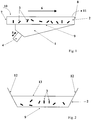
- FIG. 3 an embodiment of the invention is shown, wherein with respect to the movement of the scrap parts 3 through the conveyor trough 2 to the Figures 1 and 2
- the scrap parts 3 are sprayed from above through nozzles 14 with the liquid.
- the bottom 9 of the conveyor trough 2 rises in the conveying direction.
- the exit end 8 is open. Accordingly, the scrap parts 3 at the outlet end 8 according to the arrow 11 simply fall off the conveyor trough 2 to be caught behind the conveyor trough 2.
- FIG. 4 This alternative embodiment is shown in the front view.
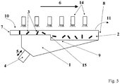
- FIG. 5 Finally, a further embodiment is shown, in principle, the embodiment according to FIG. 3 equivalent.
- a step 15 is provided within the bottom 9.
- the scrap parts 3, which are moved in the conveying direction 6 via the step 15, thus fall a piece, resulting in a rotation of the scrap parts 3 about its own axis.
- the initially lower sides of the scrap parts 3 are detected by the spray jet of the nozzles 14.
- the bottom 9 of the conveyor trough 2 in contrast to the figure in the conveying direction increases.
Landscapes
- Engineering & Computer Science (AREA)
- Chemical & Material Sciences (AREA)
- Materials Engineering (AREA)
- Mechanical Engineering (AREA)
- Geology (AREA)
- General Life Sciences & Earth Sciences (AREA)
- Manufacturing & Machinery (AREA)
- Environmental & Geological Engineering (AREA)
- Life Sciences & Earth Sciences (AREA)
- Organic Chemistry (AREA)
- Metallurgy (AREA)
- Geochemistry & Mineralogy (AREA)
- Manufacture And Refinement Of Metals (AREA)
- Refinement Of Pig-Iron, Manufacture Of Cast Iron, And Steel Manufacture Other Than In Revolving Furnaces (AREA)
- Carbon Steel Or Casting Steel Manufacturing (AREA)
- Processing Of Solid Wastes (AREA)
Applications Claiming Priority (2)
| Application Number | Priority Date | Filing Date | Title |
|---|---|---|---|
| DE201110011532 DE102011011532B3 (de) | 2011-02-17 | 2011-02-17 | Verfahren zum Ablösen von Beschichtungen von Stahlschrotten |
| PCT/EP2012/000683 WO2012110239A1 (de) | 2011-02-17 | 2012-02-16 | Verfahren zum ablösen von beschichtungen von schrotten |
Publications (2)
| Publication Number | Publication Date |
|---|---|
| EP2675929A1 EP2675929A1 (de) | 2013-12-25 |
| EP2675929B1 true EP2675929B1 (de) | 2017-12-27 |
Family
ID=45872888
Family Applications (1)
| Application Number | Title | Priority Date | Filing Date |
|---|---|---|---|
| EP12709786.3A Active EP2675929B1 (de) | 2011-02-17 | 2012-02-16 | Verfahren zum ablösen von beschichtungen von schrotten |
Country Status (7)
| Country | Link |
|---|---|
| US (1) | US9487844B2 (enExample) |
| EP (1) | EP2675929B1 (enExample) |
| JP (1) | JP2014506959A (enExample) |
| CN (1) | CN103502483B (enExample) |
| DE (1) | DE102011011532B3 (enExample) |
| ES (1) | ES2662745T3 (enExample) |
| WO (1) | WO2012110239A1 (enExample) |
Families Citing this family (7)
| Publication number | Priority date | Publication date | Assignee | Title |
|---|---|---|---|---|
| DE102014013160B4 (de) | 2014-09-11 | 2018-01-11 | ProASSORT GmbH | Verfahren und Vorrichtung zur Sortierung von wiederverwertbaren Rohstoffstücken |
| DE102015116933A1 (de) | 2015-06-25 | 2016-12-29 | Sms Group Gmbh | Verfahren und Vorrichtung zur Behandlung von Metallstücken |
| CN105862023B (zh) * | 2016-05-25 | 2018-08-03 | 王吉风 | 一种火工品底火壳金属表面处理全自动生产线及工艺 |
| DE102017103213A1 (de) | 2016-08-09 | 2018-02-15 | Sms Group Gmbh | Verfahren zur Prozessoptimierung von zu beschichtenden metallischen Bändern in kontinuierlich arbeitenden Beschichtungsanlagen |
| DE102017008530A1 (de) | 2017-09-12 | 2019-03-14 | Wieland-Werke Ag | Behandlungsvorrichtung und Verfahren zum Ablösen von Beschichtungen |
| CN114317971B (zh) * | 2022-02-24 | 2024-06-04 | 成都仁新科技股份有限公司 | 一种敲击式自动脱锡设备 |
| CN117102221B (zh) * | 2023-08-15 | 2025-07-15 | 无锡奥夫特光学技术有限公司 | 一种金属镀层回收方法及其自动化回收装置 |
Citations (1)
| Publication number | Priority date | Publication date | Assignee | Title |
|---|---|---|---|---|
| EP0211239A1 (de) * | 1985-07-09 | 1987-02-25 | Siemens Aktiengesellschaft | Behandlungseinrichtung für schüttfähiges Gut |
Family Cites Families (22)
| Publication number | Priority date | Publication date | Assignee | Title |
|---|---|---|---|---|
| US2887826A (en) * | 1957-10-30 | 1959-05-26 | Auto Specialties Mfg Co | Shot blast machine |
| GB1226755A (enExample) * | 1967-06-07 | 1971-03-31 | ||
| US3762858A (en) * | 1971-12-16 | 1973-10-02 | American Pulverizer | High temperature scrap cleaning conveyor |
| US3905882A (en) * | 1974-09-25 | 1975-09-16 | Harold G Hudson | Electrolytic zinc salvaging method |
| JPS5547674Y2 (enExample) * | 1975-07-28 | 1980-11-07 | ||
| US4022638A (en) * | 1975-08-05 | 1977-05-10 | Dart Industries Inc. | Continuous recovery of base metal from insulated wire scrap |
| US4147531A (en) * | 1977-07-27 | 1979-04-03 | Aluminum Company Of America | Method and apparatus for removing surface contaminants from metallic scrap |
| DE3206544A1 (de) * | 1982-02-24 | 1983-09-01 | Carl Schenck Ag, 6100 Darmstadt | Verfahren und schwingfoerderrinne zur behandlung eines gutes |
| JPS61222579A (ja) * | 1985-03-28 | 1986-10-03 | ミウラエンジニヤリングインタ−ナシヨナル株式会社 | 自動連続洗浄方法とその装置 |
| US4784603A (en) * | 1986-11-04 | 1988-11-15 | Aluminum Company Of America | Process for removing volatiles from metal |
| US5085999A (en) * | 1989-08-31 | 1992-02-04 | Technical Research, Inc. | Method, apparatus, and reactant for removal of paint and epoxies from metallic beverage containers using microorganisms |
| US5106467A (en) * | 1990-10-05 | 1992-04-21 | Armco Steel Company, L.P. | Alkaline leaching of galvanized steel scrap |
| JPH04210434A (ja) * | 1990-12-10 | 1992-07-31 | Nippon Steel Corp | 亜鉛鍍金鋼板屑の脱亜鉛方法 |
| JPH04280933A (ja) * | 1991-03-06 | 1992-10-06 | Nippon Steel Corp | 亜鉛鍍金鋼板屑の脱亜鉛方法及び鋼板の亜鉛抽出槽 |
| JPH064068U (ja) * | 1992-06-19 | 1994-01-18 | 神鋼電機株式会社 | 機械加工品の洗浄装置 |
| JPH0790394A (ja) * | 1993-09-22 | 1995-04-04 | Sumitomo Metal Ind Ltd | フェロスクラップの脱亜鉛方法とその装置 |
| US5855765A (en) * | 1996-07-17 | 1999-01-05 | Metal Recovery Industries, Inc. | Process for dezincing galvanized steel using an electrically isolated conveyor |
| US5779878A (en) * | 1996-07-17 | 1998-07-14 | Metal Recovery Industries (Us) Inc. | Process for dezincing galvanized steel |
| JP2001252924A (ja) * | 2000-03-10 | 2001-09-18 | Hitachi Zosen Corp | 廃プラスチック物処理装置 |
| DE102004028496B3 (de) * | 2004-06-11 | 2005-11-24 | Griag Glasrecycling Ag | Verfahren und Vorrichtung zum Entschichten von Materialchips |
| DE102008016323B4 (de) * | 2008-03-28 | 2011-07-21 | DRT Deutsche Rohstofftechnik GmbH, 45478 | Saure Entzinkung |
| DE102008048493B4 (de) | 2008-09-23 | 2011-04-28 | Drt Deutsche Rohstofftechnik Gmbh | Verfahren zur selektiven sauren Entzinkung von Stahlschrotten |
-
2011
- 2011-02-17 DE DE201110011532 patent/DE102011011532B3/de not_active Expired - Fee Related
-
2012
- 2012-02-16 EP EP12709786.3A patent/EP2675929B1/de active Active
- 2012-02-16 CN CN201280018155.7A patent/CN103502483B/zh not_active Expired - Fee Related
- 2012-02-16 ES ES12709786.3T patent/ES2662745T3/es active Active
- 2012-02-16 US US13/261,715 patent/US9487844B2/en active Active
- 2012-02-16 JP JP2013553837A patent/JP2014506959A/ja active Pending
- 2012-02-16 WO PCT/EP2012/000683 patent/WO2012110239A1/de not_active Ceased
Patent Citations (1)
| Publication number | Priority date | Publication date | Assignee | Title |
|---|---|---|---|---|
| EP0211239A1 (de) * | 1985-07-09 | 1987-02-25 | Siemens Aktiengesellschaft | Behandlungseinrichtung für schüttfähiges Gut |
Non-Patent Citations (1)
| Title |
|---|
| GOCK ET AL: "Ein neues Verfahren zur saueren Entzinkung von Stahlschrotten", March 2010 (2010-03-01), Retrieved from the Internet <URL:http://issuu.com/amsonline/docs/ams_201003> [retrieved on 20140819] * |
Also Published As
| Publication number | Publication date |
|---|---|
| CN103502483A (zh) | 2014-01-08 |
| DE102011011532B3 (de) | 2012-08-09 |
| WO2012110239A1 (de) | 2012-08-23 |
| JP2014506959A (ja) | 2014-03-20 |
| CN103502483B (zh) | 2016-04-20 |
| ES2662745T3 (es) | 2018-04-09 |
| US20140034090A1 (en) | 2014-02-06 |
| EP2675929A1 (de) | 2013-12-25 |
| US9487844B2 (en) | 2016-11-08 |
Similar Documents
| Publication | Publication Date | Title |
|---|---|---|
| EP2675929B1 (de) | Verfahren zum ablösen von beschichtungen von schrotten | |
| EP3411510B1 (de) | Feuerverzinkungsanlage sowie feuerverzinkungsverfahren | |
| DE2635201C3 (de) | Verfahren und Vorrichtung zur Wiedergewinnung von Metall aus Abfällen, insbesondere zur Wiedergewinnung des Grundmetalls aus Isolierdrahtabfällen | |
| DE102009034869A1 (de) | Verfahren zum Auftragen wenigstens eines antikorrosiven, flüssigen, Metallpartikel enthaltenden Beschichtungsmittels auf ein Werkstück sowie eine Vorrichtung hierfür | |
| EP3400318B1 (de) | Anlage zur feuerverzinkung, feuerverzinkungsverfahren und verwendung derselben | |
| DE102011118197B3 (de) | Verfahren und Vorrichtung zum Schmelztauchbeschichten eines Metallbands mit einem metallischen Überzug | |
| DE112015001729T5 (de) | Prozess zur Herstellung von Kupferanoden | |
| JP2014506959A5 (enExample) | ||
| EP3682038A1 (de) | Behandlungsvorrichtung und verfahren zum ablösen von beschichtungen | |
| DE102011077247A1 (de) | Verfahren und Vorrichtung zum Auftragen von Lot | |
| DE3212171A1 (de) | Verfahren und vorrichtung zum entfernen von durch nasslackieren oder pulverbeschichten entstandenen lackschichten auf gegenstaenden | |
| EP2678455A1 (de) | Verfahren zur rückgewinnung von hartstoffpartikeln | |
| DE102009058011A1 (de) | Anlage zum Ablösen metallischer oder organischer Beschichtungen von Stahlschrotten | |
| DE2520370C3 (de) | Vorrichtung zum Entschlacken der Oberfläche von Schmelzgut | |
| DE102011118199B3 (de) | Verfahren und Vorrichtung zum Schmelztauchbeschichten eines Metallbands mit einem metallischen Überzug | |
| DE2809702A1 (de) | Gewinnung von metall aus einer loesung durch zementation | |
| DE69811901T2 (de) | Verfahren zum entzinken galvanisierten stahls | |
| DE78344C (de) | Verfahren zur Wiedergewinnung ' des Zinns aus Weifsblechabfällen | |
| DE19621242B4 (de) | Verfahren und Einrichtung zur Rückgewinnung von durch Tauchtrommeln ausgeschleppten Behandlungslösungen | |
| EP0870068A1 (de) | Anwendung eines verfahrens fur das einschmelzen von feinstuckigem leichtmetallschrott | |
| DE9211632U1 (de) | Vorrichtung zur Oberflächenbehandlung von bandförmigem Behandlungsgut | |
| AT507510A1 (de) | Verfahren und anlage zur trockenkühlung von hüttenschlacken, wie ld-schlacke, mit wärmerückgewinnung | |
| DD214629A1 (de) | Verfahren zum schmelzen im elektronenstrahlofen | |
| CH684393A5 (de) | Recycling von Kopierzylindern, resp. von Kopiertrommeln. |
Legal Events
| Date | Code | Title | Description |
|---|---|---|---|
| PUAI | Public reference made under article 153(3) epc to a published international application that has entered the european phase |
Free format text: ORIGINAL CODE: 0009012 |
|
| 17P | Request for examination filed |
Effective date: 20130917 |
|
| AK | Designated contracting states |
Kind code of ref document: A1 Designated state(s): AL AT BE BG CH CY CZ DE DK EE ES FI FR GB GR HR HU IE IS IT LI LT LU LV MC MK MT NL NO PL PT RO RS SE SI SK SM TR |
|
| DAX | Request for extension of the european patent (deleted) | ||
| 17Q | First examination report despatched |
Effective date: 20141113 |
|
| RAP1 | Party data changed (applicant data changed or rights of an application transferred) |
Owner name: PROASSORT GMBH |
|
| GRAP | Despatch of communication of intention to grant a patent |
Free format text: ORIGINAL CODE: EPIDOSNIGR1 |
|
| INTG | Intention to grant announced |
Effective date: 20170704 |
|
| GRAS | Grant fee paid |
Free format text: ORIGINAL CODE: EPIDOSNIGR3 |
|
| GRAA | (expected) grant |
Free format text: ORIGINAL CODE: 0009210 |
|
| AK | Designated contracting states |
Kind code of ref document: B1 Designated state(s): AL AT BE BG CH CY CZ DE DK EE ES FI FR GB GR HR HU IE IS IT LI LT LU LV MC MK MT NL NO PL PT RO RS SE SI SK SM TR |
|
| REG | Reference to a national code |
Ref country code: GB Ref legal event code: FG4D Free format text: NOT ENGLISH |
|
| REG | Reference to a national code |
Ref country code: CH Ref legal event code: EP |
|
| REG | Reference to a national code |
Ref country code: AT Ref legal event code: REF Ref document number: 958357 Country of ref document: AT Kind code of ref document: T Effective date: 20180115 |
|
| REG | Reference to a national code |
Ref country code: IE Ref legal event code: FG4D Free format text: LANGUAGE OF EP DOCUMENT: GERMAN |
|
| REG | Reference to a national code |
Ref country code: DE Ref legal event code: R096 Ref document number: 502012011899 Country of ref document: DE |
|
| REG | Reference to a national code |
Ref country code: FR Ref legal event code: PLFP Year of fee payment: 7 |
|
| REG | Reference to a national code |
Ref country code: NL Ref legal event code: FP |
|
| REG | Reference to a national code |
Ref country code: ES Ref legal event code: FG2A Ref document number: 2662745 Country of ref document: ES Kind code of ref document: T3 Effective date: 20180409 |
|
| PG25 | Lapsed in a contracting state [announced via postgrant information from national office to epo] |
Ref country code: LT Free format text: LAPSE BECAUSE OF FAILURE TO SUBMIT A TRANSLATION OF THE DESCRIPTION OR TO PAY THE FEE WITHIN THE PRESCRIBED TIME-LIMIT Effective date: 20171227 Ref country code: FI Free format text: LAPSE BECAUSE OF FAILURE TO SUBMIT A TRANSLATION OF THE DESCRIPTION OR TO PAY THE FEE WITHIN THE PRESCRIBED TIME-LIMIT Effective date: 20171227 Ref country code: NO Free format text: LAPSE BECAUSE OF FAILURE TO SUBMIT A TRANSLATION OF THE DESCRIPTION OR TO PAY THE FEE WITHIN THE PRESCRIBED TIME-LIMIT Effective date: 20180327 |
|
| PGFP | Annual fee paid to national office [announced via postgrant information from national office to epo] |
Ref country code: ES Payment date: 20180327 Year of fee payment: 7 Ref country code: GB Payment date: 20180227 Year of fee payment: 7 |
|
| REG | Reference to a national code |
Ref country code: LT Ref legal event code: MG4D |
|
| PG25 | Lapsed in a contracting state [announced via postgrant information from national office to epo] |
Ref country code: GR Free format text: LAPSE BECAUSE OF FAILURE TO SUBMIT A TRANSLATION OF THE DESCRIPTION OR TO PAY THE FEE WITHIN THE PRESCRIBED TIME-LIMIT Effective date: 20180328 Ref country code: HR Free format text: LAPSE BECAUSE OF FAILURE TO SUBMIT A TRANSLATION OF THE DESCRIPTION OR TO PAY THE FEE WITHIN THE PRESCRIBED TIME-LIMIT Effective date: 20171227 Ref country code: BG Free format text: LAPSE BECAUSE OF FAILURE TO SUBMIT A TRANSLATION OF THE DESCRIPTION OR TO PAY THE FEE WITHIN THE PRESCRIBED TIME-LIMIT Effective date: 20180327 Ref country code: LV Free format text: LAPSE BECAUSE OF FAILURE TO SUBMIT A TRANSLATION OF THE DESCRIPTION OR TO PAY THE FEE WITHIN THE PRESCRIBED TIME-LIMIT Effective date: 20171227 Ref country code: RS Free format text: LAPSE BECAUSE OF FAILURE TO SUBMIT A TRANSLATION OF THE DESCRIPTION OR TO PAY THE FEE WITHIN THE PRESCRIBED TIME-LIMIT Effective date: 20171227 |
|
| PGFP | Annual fee paid to national office [announced via postgrant information from national office to epo] |
Ref country code: AT Payment date: 20180301 Year of fee payment: 7 |
|
| PG25 | Lapsed in a contracting state [announced via postgrant information from national office to epo] |
Ref country code: CY Free format text: LAPSE BECAUSE OF FAILURE TO SUBMIT A TRANSLATION OF THE DESCRIPTION OR TO PAY THE FEE WITHIN THE PRESCRIBED TIME-LIMIT Effective date: 20171227 Ref country code: EE Free format text: LAPSE BECAUSE OF FAILURE TO SUBMIT A TRANSLATION OF THE DESCRIPTION OR TO PAY THE FEE WITHIN THE PRESCRIBED TIME-LIMIT Effective date: 20171227 Ref country code: CZ Free format text: LAPSE BECAUSE OF FAILURE TO SUBMIT A TRANSLATION OF THE DESCRIPTION OR TO PAY THE FEE WITHIN THE PRESCRIBED TIME-LIMIT Effective date: 20171227 Ref country code: SK Free format text: LAPSE BECAUSE OF FAILURE TO SUBMIT A TRANSLATION OF THE DESCRIPTION OR TO PAY THE FEE WITHIN THE PRESCRIBED TIME-LIMIT Effective date: 20171227 |
|
| PG25 | Lapsed in a contracting state [announced via postgrant information from national office to epo] |
Ref country code: PL Free format text: LAPSE BECAUSE OF FAILURE TO SUBMIT A TRANSLATION OF THE DESCRIPTION OR TO PAY THE FEE WITHIN THE PRESCRIBED TIME-LIMIT Effective date: 20171227 Ref country code: SM Free format text: LAPSE BECAUSE OF FAILURE TO SUBMIT A TRANSLATION OF THE DESCRIPTION OR TO PAY THE FEE WITHIN THE PRESCRIBED TIME-LIMIT Effective date: 20171227 Ref country code: IS Free format text: LAPSE BECAUSE OF FAILURE TO SUBMIT A TRANSLATION OF THE DESCRIPTION OR TO PAY THE FEE WITHIN THE PRESCRIBED TIME-LIMIT Effective date: 20180427 Ref country code: RO Free format text: LAPSE BECAUSE OF FAILURE TO SUBMIT A TRANSLATION OF THE DESCRIPTION OR TO PAY THE FEE WITHIN THE PRESCRIBED TIME-LIMIT Effective date: 20171227 Ref country code: IT Free format text: LAPSE BECAUSE OF FAILURE TO SUBMIT A TRANSLATION OF THE DESCRIPTION OR TO PAY THE FEE WITHIN THE PRESCRIBED TIME-LIMIT Effective date: 20171227 |
|
| REG | Reference to a national code |
Ref country code: CH Ref legal event code: PL |
|
| PG25 | Lapsed in a contracting state [announced via postgrant information from national office to epo] |
Ref country code: MC Free format text: LAPSE BECAUSE OF FAILURE TO SUBMIT A TRANSLATION OF THE DESCRIPTION OR TO PAY THE FEE WITHIN THE PRESCRIBED TIME-LIMIT Effective date: 20171227 Ref country code: MT Free format text: LAPSE BECAUSE OF FAILURE TO SUBMIT A TRANSLATION OF THE DESCRIPTION OR TO PAY THE FEE WITHIN THE PRESCRIBED TIME-LIMIT Effective date: 20171227 |
|
| REG | Reference to a national code |
Ref country code: DE Ref legal event code: R097 Ref document number: 502012011899 Country of ref document: DE |
|
| PLBE | No opposition filed within time limit |
Free format text: ORIGINAL CODE: 0009261 |
|
| STAA | Information on the status of an ep patent application or granted ep patent |
Free format text: STATUS: NO OPPOSITION FILED WITHIN TIME LIMIT |
|
| REG | Reference to a national code |
Ref country code: IE Ref legal event code: MM4A |
|
| REG | Reference to a national code |
Ref country code: BE Ref legal event code: MM Effective date: 20180228 |
|
| PG25 | Lapsed in a contracting state [announced via postgrant information from national office to epo] |
Ref country code: LU Free format text: LAPSE BECAUSE OF NON-PAYMENT OF DUE FEES Effective date: 20180216 Ref country code: LI Free format text: LAPSE BECAUSE OF NON-PAYMENT OF DUE FEES Effective date: 20180228 Ref country code: CH Free format text: LAPSE BECAUSE OF NON-PAYMENT OF DUE FEES Effective date: 20180228 Ref country code: DK Free format text: LAPSE BECAUSE OF FAILURE TO SUBMIT A TRANSLATION OF THE DESCRIPTION OR TO PAY THE FEE WITHIN THE PRESCRIBED TIME-LIMIT Effective date: 20171227 |
|
| 26N | No opposition filed |
Effective date: 20180928 |
|
| PG25 | Lapsed in a contracting state [announced via postgrant information from national office to epo] |
Ref country code: IE Free format text: LAPSE BECAUSE OF NON-PAYMENT OF DUE FEES Effective date: 20180216 |
|
| PG25 | Lapsed in a contracting state [announced via postgrant information from national office to epo] |
Ref country code: SI Free format text: LAPSE BECAUSE OF FAILURE TO SUBMIT A TRANSLATION OF THE DESCRIPTION OR TO PAY THE FEE WITHIN THE PRESCRIBED TIME-LIMIT Effective date: 20171227 Ref country code: BE Free format text: LAPSE BECAUSE OF NON-PAYMENT OF DUE FEES Effective date: 20180228 |
|
| REG | Reference to a national code |
Ref country code: AT Ref legal event code: MM01 Ref document number: 958357 Country of ref document: AT Kind code of ref document: T Effective date: 20190216 |
|
| GBPC | Gb: european patent ceased through non-payment of renewal fee |
Effective date: 20190216 |
|
| PG25 | Lapsed in a contracting state [announced via postgrant information from national office to epo] |
Ref country code: AT Free format text: LAPSE BECAUSE OF NON-PAYMENT OF DUE FEES Effective date: 20190216 |
|
| PG25 | Lapsed in a contracting state [announced via postgrant information from national office to epo] |
Ref country code: GB Free format text: LAPSE BECAUSE OF NON-PAYMENT OF DUE FEES Effective date: 20190216 |
|
| REG | Reference to a national code |
Ref country code: ES Ref legal event code: FD2A Effective date: 20200330 |
|
| PG25 | Lapsed in a contracting state [announced via postgrant information from national office to epo] |
Ref country code: TR Free format text: LAPSE BECAUSE OF FAILURE TO SUBMIT A TRANSLATION OF THE DESCRIPTION OR TO PAY THE FEE WITHIN THE PRESCRIBED TIME-LIMIT Effective date: 20171227 |
|
| PG25 | Lapsed in a contracting state [announced via postgrant information from national office to epo] |
Ref country code: ES Free format text: LAPSE BECAUSE OF NON-PAYMENT OF DUE FEES Effective date: 20190217 |
|
| PG25 | Lapsed in a contracting state [announced via postgrant information from national office to epo] |
Ref country code: PT Free format text: LAPSE BECAUSE OF FAILURE TO SUBMIT A TRANSLATION OF THE DESCRIPTION OR TO PAY THE FEE WITHIN THE PRESCRIBED TIME-LIMIT Effective date: 20171227 Ref country code: HU Free format text: LAPSE BECAUSE OF FAILURE TO SUBMIT A TRANSLATION OF THE DESCRIPTION OR TO PAY THE FEE WITHIN THE PRESCRIBED TIME-LIMIT; INVALID AB INITIO Effective date: 20120216 |
|
| PG25 | Lapsed in a contracting state [announced via postgrant information from national office to epo] |
Ref country code: SE Free format text: LAPSE BECAUSE OF FAILURE TO SUBMIT A TRANSLATION OF THE DESCRIPTION OR TO PAY THE FEE WITHIN THE PRESCRIBED TIME-LIMIT Effective date: 20171227 Ref country code: MK Free format text: LAPSE BECAUSE OF NON-PAYMENT OF DUE FEES Effective date: 20171227 |
|
| PG25 | Lapsed in a contracting state [announced via postgrant information from national office to epo] |
Ref country code: AL Free format text: LAPSE BECAUSE OF FAILURE TO SUBMIT A TRANSLATION OF THE DESCRIPTION OR TO PAY THE FEE WITHIN THE PRESCRIBED TIME-LIMIT Effective date: 20171227 |
|
| P01 | Opt-out of the competence of the unified patent court (upc) registered |
Effective date: 20230522 |
|
| PGFP | Annual fee paid to national office [announced via postgrant information from national office to epo] |
Ref country code: NL Payment date: 20240320 Year of fee payment: 13 |
|
| PGFP | Annual fee paid to national office [announced via postgrant information from national office to epo] |
Ref country code: FR Payment date: 20240321 Year of fee payment: 13 |
|
| PGFP | Annual fee paid to national office [announced via postgrant information from national office to epo] |
Ref country code: DE Payment date: 20250218 Year of fee payment: 14 |
|
| REG | Reference to a national code |
Ref country code: NL Ref legal event code: MM Effective date: 20250301 |
|
| PG25 | Lapsed in a contracting state [announced via postgrant information from national office to epo] |
Ref country code: NL Free format text: LAPSE BECAUSE OF NON-PAYMENT OF DUE FEES Effective date: 20250301 |