EP2675693B1 - Structure de support pour une suspension de roue de véhicule - Google Patents
Structure de support pour une suspension de roue de véhicule Download PDFInfo
- Publication number
- EP2675693B1 EP2675693B1 EP12705500.2A EP12705500A EP2675693B1 EP 2675693 B1 EP2675693 B1 EP 2675693B1 EP 12705500 A EP12705500 A EP 12705500A EP 2675693 B1 EP2675693 B1 EP 2675693B1
- Authority
- EP
- European Patent Office
- Prior art keywords
- support assembly
- assembly according
- transverse body
- anchoring
- mounting
- Prior art date
- Legal status (The legal status is an assumption and is not a legal conclusion. Google has not performed a legal analysis and makes no representation as to the accuracy of the status listed.)
- Active
Links
Images


Classifications
-
- B—PERFORMING OPERATIONS; TRANSPORTING
- B62—LAND VEHICLES FOR TRAVELLING OTHERWISE THAN ON RAILS
- B62D—MOTOR VEHICLES; TRAILERS
- B62D21/00—Understructures, i.e. chassis frame on which a vehicle body may be mounted
- B62D21/11—Understructures, i.e. chassis frame on which a vehicle body may be mounted with resilient means for suspension, e.g. of wheels or engine; sub-frames for mounting engine or suspensions
-
- B—PERFORMING OPERATIONS; TRANSPORTING
- B62—LAND VEHICLES FOR TRAVELLING OTHERWISE THAN ON RAILS
- B62D—MOTOR VEHICLES; TRAILERS
- B62D21/00—Understructures, i.e. chassis frame on which a vehicle body may be mounted
- B62D21/02—Understructures, i.e. chassis frame on which a vehicle body may be mounted comprising longitudinally or transversely arranged frame members
-
- B—PERFORMING OPERATIONS; TRANSPORTING
- B62—LAND VEHICLES FOR TRAVELLING OTHERWISE THAN ON RAILS
- B62D—MOTOR VEHICLES; TRAILERS
- B62D53/00—Tractor-trailer combinations; Road trains
- B62D53/04—Tractor-trailer combinations; Road trains comprising a vehicle carrying an essential part of the other vehicle's load by having supporting means for the front or rear part of the other vehicle
- B62D53/08—Fifth wheel traction couplings
-
- B—PERFORMING OPERATIONS; TRANSPORTING
- B60—VEHICLES IN GENERAL
- B60G—VEHICLE SUSPENSION ARRANGEMENTS
- B60G2200/00—Indexing codes relating to suspension types
- B60G2200/30—Rigid axle suspensions
- B60G2200/314—Rigid axle suspensions with longitudinally arranged arms articulated on the axle
-
- B—PERFORMING OPERATIONS; TRANSPORTING
- B60—VEHICLES IN GENERAL
- B60G—VEHICLE SUSPENSION ARRANGEMENTS
- B60G2200/00—Indexing codes relating to suspension types
- B60G2200/30—Rigid axle suspensions
- B60G2200/314—Rigid axle suspensions with longitudinally arranged arms articulated on the axle
- B60G2200/315—Rigid axle suspensions with longitudinally arranged arms articulated on the axle at least one of the arms having an A or V shape
-
- B—PERFORMING OPERATIONS; TRANSPORTING
- B60—VEHICLES IN GENERAL
- B60G—VEHICLE SUSPENSION ARRANGEMENTS
- B60G2200/00—Indexing codes relating to suspension types
- B60G2200/30—Rigid axle suspensions
- B60G2200/34—Stabilising mechanisms, e.g. for lateral stability
- B60G2200/343—Stabilising mechanisms, e.g. for lateral stability with an axle suspended by two pivoted rods in "V"-arrangement, the rods being coupled at its apex
-
- B—PERFORMING OPERATIONS; TRANSPORTING
- B60—VEHICLES IN GENERAL
- B60G—VEHICLE SUSPENSION ARRANGEMENTS
- B60G2200/00—Indexing codes relating to suspension types
- B60G2200/30—Rigid axle suspensions
- B60G2200/34—Stabilising mechanisms, e.g. for lateral stability
- B60G2200/345—Stabilising mechanisms, e.g. for lateral stability with an axle suspended by two pivoted rods in "X"-arrangement
-
- B—PERFORMING OPERATIONS; TRANSPORTING
- B60—VEHICLES IN GENERAL
- B60G—VEHICLE SUSPENSION ARRANGEMENTS
- B60G2202/00—Indexing codes relating to the type of spring, damper or actuator
- B60G2202/10—Type of spring
- B60G2202/15—Fluid spring
- B60G2202/152—Pneumatic spring
-
- B—PERFORMING OPERATIONS; TRANSPORTING
- B60—VEHICLES IN GENERAL
- B60G—VEHICLE SUSPENSION ARRANGEMENTS
- B60G2204/00—Indexing codes related to suspensions per se or to auxiliary parts
- B60G2204/10—Mounting of suspension elements
- B60G2204/15—Mounting of subframes
-
- B—PERFORMING OPERATIONS; TRANSPORTING
- B60—VEHICLES IN GENERAL
- B60G—VEHICLE SUSPENSION ARRANGEMENTS
- B60G2204/00—Indexing codes related to suspensions per se or to auxiliary parts
- B60G2204/40—Auxiliary suspension parts; Adjustment of suspensions
- B60G2204/47—Means for retracting the suspension
-
- B—PERFORMING OPERATIONS; TRANSPORTING
- B60—VEHICLES IN GENERAL
- B60G—VEHICLE SUSPENSION ARRANGEMENTS
- B60G2206/00—Indexing codes related to the manufacturing of suspensions: constructional features, the materials used, procedures or tools
- B60G2206/01—Constructional features of suspension elements, e.g. arms, dampers, springs
- B60G2206/60—Subframe construction
- B60G2206/606—Complex constructions
-
- B—PERFORMING OPERATIONS; TRANSPORTING
- B60—VEHICLES IN GENERAL
- B60G—VEHICLE SUSPENSION ARRANGEMENTS
- B60G2300/00—Indexing codes relating to the type of vehicle
- B60G2300/02—Trucks; Load vehicles
- B60G2300/026—Heavy duty trucks
Definitions
- the invention relates to a support structure for inclusion in a vehicle structure for receiving wheel suspension means. More in particular the invention relates to such a support structure that combines a cross brace between left and right hand longitudinal frame rails of a vehicular chassis frame with mounting facilities for wheel and axle suspensions. The invention also relates to a tractor vehicle for towing semi-trailers or non-articulated trucks including the support assembly.
- a support structure of this kind is known from Japanese published patent application JP-A 11-310151 and uses an integrally formed cross member and a pair of separate suspension trunnion brackets.
- the suspension trunnion brackets are separately bolted to flange portions on the lower side of the integrally formed cross member.
- this structure has the advantage that it can be preassembled and mounted between the longerons of a vehicle frame as a unit, it may lack in stability and structural integrity over the conventional use of suspension trunnion brackets that are separately attached to the chassis longerons.
- Another concern with the known arrangements is their contribution to vehicle weight, which reduces the available payload and also adds to the environmental implications of fuel consumption.
- an object of the present invention to propose an improved support assembly for receiving a vehicle wheel suspension and tractor vehicle for towing semi-trailers including the support assembly.
- the invention provides a support assembly for receiving a vehicle wheel suspension and tractor or truck including the support assembly in accordance with one or more of the appended claims.
- the support assembly according to the invention offers integrated mounting facilities for all wheel suspension guiding linkages, radius rods and anti-roll provisions. This results in a significant reduction of assembly time and errors in production. It also enables direct mounting of a fifth wheel trailer coupling.
- a further weight saving is notably achieved by the strategic use of an integrally formed element that is formed as one of a unitary forging, a unitary casting, a unitary moulding and a unitary sintered component, and separately attached left and right hand reinforcing elements of high strength sheet metal.
- the high strength sheet metal reinforcements each extend from an outside of an adjacent chassis beam to a connecting area on an adjacent downwardly extending anchoring strut in the vicinity of a distal lower end of the respective strut. This results in a weight saving of up to about 25% with respect to an integrally formed support structure, without the benefit of reinforcing elements.
- the reinforcing elements transmit the forces acting on the anchoring struts directly into the chassis. It is thereby further possible to integrate a fifth wheel mounting rail into the reinforcing elements. Fifth wheel loads can be very high and complimentary measures are desirable to transfer these loads not only to the chassis, but also to the wheel suspension.
- Such external reinforcing elements can also be topologically optimized and may have an open space frame structure to avoid buckling.
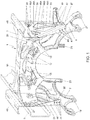
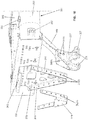
- FIG. 1 a combined vehicle frame cross brace and wheel suspension carrier, briefly referred to as wheel suspension carrier 1, is shown.
- the wheel suspension carrier 1 has a transverse body 3 that is adapted to extend between opposite frame members; of which only a right-hand one having reference numeral 5 is shown in dotted lines.
- the right-hand and left-hand struts 7, 9 are integrally formed with the transverse body 3 as a unitary forging, casting moulding or sintered structure.
- This unitary structure has first and second pairs of upper suspension linkage anchoring mountings 11, 13 on its transverse body 3.
- the right and left-hand struts 7, 9 are each provided with one of a first and a second pair of radius rod anchoring mountings 19, 21.
- first and second lift actuator connections 23, 25 On opposite lateral ends the transverse body 3 has right-hand and left-hand mounting flanges 27, 29 for mounting between right-hand 5 and left-hand frame members respectively. Thereby each mounting flange 27, 29 engages the inside web of the relevant frame member.
- first and second external reinforcement brackets or elements 31, 33 are arranged to extend between a strut area 35, 37 of the right-hand and left-hand struts 7, 9 in the vicinity of the first and second pairs of radius rod anchoring mountings 19, 21 respectively, and the outside of each frame member web.
- each reinforcement bracket 31, 33 has a series of upper and lower mounting apertures 39, 41 through which bolts may engage (not shown, but conventional).
- the first and second reinforcement brackets 31, 33 are preferably from high strength sheet steel and each comprise an integrated mounting flange 43, 45 for assisting in the mounting of a fifth wheel trailer saddle coupling.
- the lower mounting apertures 41 are positioned on inturned flanges 44, which further reinforce the external brackets 31, 33 and form-fit the strut areas 35, 37 in vicinity of the radius rod anchoring points.
- Further mounting holes 47 may be provided in the strut areas 35, 37 for reinforcing the connection of the external brackets 31, 33 to the struts 7, 9, but also to mount a steering actuator bracket 49 using the same further mounting holes 47.
- the external reinforcing elements 31, 33 as shown in the drawing figures, may have an open space frame structure defined by triangular openings 46A, 46B, spaced by connecting struts 48A, 48B.
- This tripoid arrangement of connecting struts 48A, 48B is both light and sufficiently stiff and in combination with the inturned flanges 44 avoid buckling.
- the inturned flanges 44 thereby form concentrations of structural material in the outer edge regions of the generally triangular external reinforcement brackets 31, 33.
- a central mounting platform 50 on the transverse body 3 may be further useful in the mounting of a trailer coupling.
- the flanges 44 along the downwardly converging outer front and rear edges of the reinforcing elements 31 need not necessarily be turned inwardly only.
- the reinforcing (anti-buckling) properties can also be obtained by directing these flanges outwardly.
- the relevant feature is that these flanges are deflected in a direction perpendicular to a plane through the main web of the reinforcing bracket or element.
- the wheel suspension carrier and chassis cross member assembly can receive an axle lift arm 51 and axle lift actuators 53, 55.
- the actuators 53, 55 extend respectively between the first and second lift actuator connections 23, 25 and a relevant distal end 57, 59 of the lift arm 51.
- the articulations at both ends of the actuators 53, 55 can make use of ball joints, using steel balls.
- the lift arm 51 is pivotally connected to the first and second pair of lift arm anchorage mountings 15, 17 by elastomeric ball-and-socket joints 61.
- the ball-and-socket joints 61 can be of a type as disclosed by US 4,129,394 , US 5,846 , 014 or US 6,719,476 , but also of another suitable type.
- a steering actuator hydraulic cylinder 63 mounted to the steering actuator bracket 49 is a steering actuator hydraulic cylinder 63.
- the articulations on both ends of the steering actuator 63 are preferably steel ball joints to prove a possibly stiff force transmission path.
- Figure 3 a view from the opposite rear side of the wheel suspension carrier 1 of Figure 2 is shown. From this view it is apparent that the rear side of the transverse body 3 is provided with third and fourth pairs of upper suspension linkage anchorage mountings 65, 67.
- the other reference numerals correspond with those already described in reference to Figures 1 and 2 .
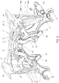
- Figures 4 and 5 show the rear wheel assembly of a freight vehicle tractor including a combined vehicle frame cross member and wheel suspension carrier 1A, similar to that disclosed in Figures 1-3 .
- Figure 4 in an isometric front view a portion of the right-hand frame member 5 and a portion of the left-hand frame member 107 is shown. This portion of a vehicle frame corresponds to a rear end of the chassis, when viewed opposite to the normal driving direction.
- the right- and left-hand frame members 5, 107 can both extend further forwardly and further rearwardly, but those conventional portions of a freight vehicle are not required for the understanding of the present arrangement which is primarily concerned with the rear wheel suspension of such a vehicle. It is further seen in Figure 4 that the rear axle assembly has mid or pusher axle hubs 109 and rear axle hubs 111. The mid or pusher axle hubs 109 are each pivotally mounted to a liftable mid or pusher axle 113.
- the liftable mid or pusher axle 113 is suspended by air bellows 115, 117 and connected by lower radius rods (hidden from view by the mid or pusher axle 113, but generally conventional) to the first and second pairs of radius rod anchoring mountings 19, 21 (see Figures 1-3 ).
- an upper linkage 119 is pivoted to a pair of upstanding axle struts 121 by means of further elastomeric ball-and-socket joints 61.
- the upper linkage 119 is here in the form of a quadrangle which also resists vehicle roll with respect to the axle 113 in a predetermined amount.
- the upper linkage 119 is also pivotally mounted to the first and second pairs of upper suspension anchoring mountings 11, 13 by means of further ball-and-socket joints 61.
- a drive shaft to the rear axle (not shown, but conventional) can extend between the upstanding axle struts 121.
- the liftable mid or pusher axle 113 is further seen to be provided with telescopic shock absorbers 123, which are mounted in pairs on each side of the suspension air bellows 115, 117.
- the second reinforcing bracket 33 is mounted to the outside surface of the web of the frame member 107.
- the mounting of first reinforcing bracket 31 to frame member 5 is similar, but hidden from view in Figure 4 .
- a trailer coupling 125 can be mounted from the mounting flanges 43, 45 integrated with the reinforcing bracket 31, 33.
- This trailer coupling 125 as shown can be further mounted to central mounting platform 50 of the suspension carrier, using a diagonal cross brace 126.
- the diagonal cross brace is combined with the transverse body that is also associated with the axle suspension of the tractor or non-articulated truck. In such an arrangement the diagonal bracing is positioned directly between the pivot bearings for the coupling saddle 125 and the chassis traverse, enabling transfer of forces directly to the wheel suspension anchoring points.
- This mounting arrangement for trailer couplings results in a more weight optimal and less complex construction, with increased torsional stiffness for a tractor or truck chassis.
- the steering actuator cylinder 63 is connected to the left-hand mid or pusher axle hub 109.
- the left-hand and right-hand mid or pusher axle hubs 109 are linked to one another by a track rod (as is conventional in vehicle steering), then only the one actuator cylinder 63 will be required.
- the rear hubs 111 are mounted on a driven rear axle 127.
- the driven rear axle 127 is also suspended by air bellows 117 in conjunction with telescopic shock absorbers 123.
- the driven rear axle 127 is similarly guided by the wheel suspension carrier 1 as is the liftable mid or pusher axle 113 as described in reference to Figure 4 .
- This means that the driven rear axle 127 is linked by lower radius rods or radius arms to the first an second pairs of anchoring mountings 19, 21 (see Figure 3 ).
- the lower radius rods or arms may be the parallel arms of a so-called “stabilenker", which is also useful in controlling vehicle roll.
- Guidance of the upper end of the driven axle 127 is taken care of by an upper linkage in the form of triangle 129.
- the upper triangle 129 is pivotally linked to the upper anchorage mountings 65, 67 (see also Figure 3 ) by again elastomeric ball-and-socket joints 61.
- a similar ball-and-socket joint 61 may be used to pivotally connect an upper end of the rear axle 127 to an apex of the triangle link 129.
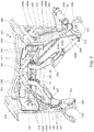
- Figure 6 , 7 and 8 are views similar to Figures 1 , 2 and 3 and show a second embodiment of wheel suspension carrier 201. Similar reference numerals to those of the first embodiment, but differing by the addition of a full "200", will be used to denote corresponding elements.
- the combined frame cross member and wheel suspension carrier 201 has a transverse body 203 and downwardly depending right-hand and left-hand struts 207, 209.
- the transverse body 203 is again provided with first and second pairs of anchoring mountings 211, 213 for an upper suspension linkage.
- first and second pairs of lift arm anchorage mounting 215, 217 Inwardly of the first and second pairs of anchorage mounting 211, 213 are first and second pairs of lift arm anchorage mounting 215, 217.
- first and second lift actuator connections 223, 225 are located adjacent the first and second pairs of radius rod mountings 219, 221 respectively.
- the transverse body 203 which acts as the frame cross member of a vehicle frame, is provided with right- and left-hand mounting flanges 227, 229 for being mounted between the inwardly directed surfaces of frame member webs (not shown in Figures 6-8 , but conventional). Destined for mounting to the outwardly directed webs of such parallel frame members are first and second external reinforcement brackets 231, 233. As described in reference to the first embodiment, in use, each one of a pair of parallel frame members will be sandwiched between the relevant left-or right-hand mounting flange 227, 229 and a confronting one of the first and second external reinforcement brackets 231, 233.
- each of the external reinforcement brackets attaches to a relevant one of the downwardly extending struts 207, 209.
- a series of upper mounting apertures 239 and a series of lower mounting apertures 241 is provided for the attachment of the external reinforcement brackets 231, 233 .
- the lower mounting holes 241 provide attachment to connecting areas in the vicinity of a lower distal end of the right and left hand struts 207, 209.
- One of the strut connecting areas 235 is shown in Figure 6 .
- first and second reinforcement brackets 231, 232 also have their lower mounting apertures 241 positioned on inturned flanges 244, for further reinforcement and form-fitting to the strut areas (such as 235) in vicinity of the radius rod anchoring points.
- the external reinforcing elements 231, 233 as shown, preferably are provided with an open space frame structure formed by triangular openings 246A, 246B, separated by connecting struts 248A, 248B.
- the connecting struts 248A, 248B, together with the plurality of strut formations 226A, 226B, 226C, 226D form tripoids.
- a central section of the transverse body 203 may serve as a central mounting platform 250 for mounting of a trailer coupling (as shown in Figures 4 and 5 ). Such a trailer coupling will also be mounted on outwardly extending mounting flanges 243, 245 that are integral with the relevant first or second reinforcement bracket 231, 233.
- axle lift arm 251 may be pivotally connected to the first and second pairs of lift arm mountings 215, 217. This pivotal mounting may again be obtained by elastomeric ball-and-socket joints 61, identical to the first embodiment.
- Axle lift actuator 253, 255 now each extend between the relevant low positioned first and second lift actuator connections 223, 225 and opposite distal ends 257, 259 of the bifurcated lift arm 251.
- the mid or pusher axle lift arm 251 in contrast to the axle lift arm of the first embodiment, has been given an H-shape, by an intermediate tubular connection 260 between the lift arm ends 257, 259.
- the thus reinforced axle lift arm 251 has an improved transverse resistance when the lift actuators 253, 255 are not positioned strictly in parallel.
- the best reinforcement and thereby lightest axle lift arm would clearly be obtained when the intermediate tubular reinforcement connection would extend directly between the opposite distal ends 257, 259, effectively producing an U-shape, but such a position would interfere with the drive shaft.
- the preference for an H-shape with the tubular reinforcement 260 as close as possible to the distal ends 257, 259 of the axle lift arm 251.
- Connected to the steering actuator bracket 249 is again a hydraulic steering actuator 63, which is identical to that of the first embodiment.
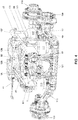
- a third embodiment of wheel suspension carrier 301 is shown in Figures 9 and 10 .
- a transverse body 303 is shaped a hollow substantially tubular cross member for mounting between facing inside webs of opposite right-hand and left-hand chassis rails 305, 306 (shown in Figure 10 ).
- the transverse body 303 has opposite first and second mounting flanges 327, 329 with several mounting holes 339.
- the substantially tubular transverse body 303 can be generally circular in cross section, it advantageously has a somewhat elliptical cross section, so that it is wider in a fore to aft direction of the vehicle than in a vertical direction.
- Right-hand and left-hand struts 307, 309 are extending downwardly and outwardly from the transverse body 303.
- a bowl-shaped mounting area 335 At a distal end of the right-hand strut 307 is formed a bowl-shaped mounting area 335, which at a lower end includes a first pair of radius rod mountings 319, as well as a first lift actuator connection 323.
- the distal end of the left-hand strut 309 has a mounting area 337 with a second pair of radius rod mountings 321 and a second lift actuator connection 325.
- each strut area 335, 337 is formed integrally with each strut area 335, 337 in vicinity of the radius rod mountings 319, 321 .
- the hollow shape of the transverse body 303 and the bowl-shaped mounting areas 335, 337 result in optimized weight reduction, while retaining and even improving strength and stiffness.
- the transverse body 303 has first and second pairs of upper suspension linkage mountings 311, 313, as well as first and second pairs of lift arm pivot mountings 315, 317.
- a mounting platform 350 may be provided to assist in the mounting of an optional trailer coupling (similar to that shown in Figures 4 and 5 ).
- a separately attached external reinforcement element 333 will be attached upon assembly. Thereby the reinforcing element 333 will extend between the mounting area 337 and a location on the outer web of the left-hand chassis rail 306, where the transverse body 303 attaches to the inside web by means of its mounting flange 327.
- the reinforcing element further has outwardly turned flanges 344, which snugly fit into the bowl-shaped mounting area 335.
- Mounting openings 341B are provided in the flanges 344 to correspond to the mounting holes 341A to receive fasteners (not shown, but conventional).
- the outwardly turned flanges 344 form concentrations of structural material in the outer edge regions of the generally triangular external reinforcement brackets, such as 333, and prevent buckling.
- the outwardly turned flanges may further be used for the attachment of shock absorber mounting brackets or additional load distribution brackets.
- An upper end of the generally triangularly shaped reinforcing element 333 is also provided with a mounting flange 345 for supporting and mounting a trailer coupling. Also visible in Figure 10 is that a rear side of the transverse body 303 has a fourth pair of upper suspension linkage mountings in an arrangement very similar to the previously described embodiments. A further description of the various anchorage mountings is therefore deemed superfluous for the present embodiment.
- a further feature of this third embodiment 301 is an optional insert piece 371 that can be used to connect a bracket for a hydraulic steering actuator on at least one side of the vehicle.
- Use of the insert piece 371 has the added benefit of additionally strengthening the lower ends of the struts 307, 309 by being bolted or riveted to the lower mounting areas 335, 337 by means of holes 341C.
- the cross-sectional properties were optimized within the space available for the axle suspension support structure. Even with the assistance of computerized design optimization final adjustments and modifications of the design by human interference are required to ensure manufacturability. Particular characteristics of the improved component design can be obtained by combined computer optimization and human interference.
- a four stage design process has been found very useful in arriving at the weight saving shape of the combined frame cross member and wheel suspension carrier of the presently disclosed embodiments. In a first step of this design process the dimensional constraints or design space for the integral cross member was defined. In a second step load measurements and data acquisition from stress analysis and life cycle tests were translated into specific loads of the integral cross member.
- the dimensional boundaries of the first step and the loads of the second step are then subjected to a topological optimization for various load conditions.
- the third step results in a distribution of material concentrations and material reductions within the dimensional boundaries.
- the result of the third step is not yet necessarily in a form that is practical for use as an integral cross member and may still lack material concentrations in locations where fasteners need to be used for mechanical connections. Conversely there may be material concentration in locations where it is less practical or desirable to have a dense structure.
- CAD computer aided design
- a substantial benefit of various cavities and openings in the structural shapes of the first and second embodiments 1, 201 is that in manufacturing a more equal distribution of wall thicknesses is obtained.
- a possible equal wall thickness may be a prerequisite when the carrier 1, 201 is obtained as a casting, but may also be favourable in forging, moulding or sintering operations. While casting in ductile or spherical graphite cast iron is an attractive manufacturing option for the combined cross member carrier 1, 201, also forgings in steel or light alloy and powder metallurgy in sintered structures are not to be excluded as possible alternatives. Good results however can be obtained with castings in a GGG50 material.
- the support structure may integrally be formed as one of a one-piece forging, a one-piece casting, a one-piece moulding and a one-piece sintered part, it is alternatively possible for it to be compiled from individual elements that may be bolted together.
- the support structure according to such an alternative can be divided in mirrored or non-mirrored left hand and right hand parts for connection to the respective left and right chassis frame sides. These separate left and right vehicle side parts can then be connected together by means of an intermediate section.
- This intermediate section if so desired, can be of a non-casted material, such as plate material. With such a separate intermediate section, vehicle width variations can easily be accommodated.
- Such an alternative arrangement can also have economical advantages.
- a support assembly for receiving a vehicle wheel suspension and adapted for mounting to a vehicle structure includes: a transverse body 3, 203, 303 having opposite ends; a left hand anchoring strut 9, 209, 309 extending downwardly from the transverse body 3, 203, 303 to define a distal left hand lower end; a right hand anchoring strut 7, 207, 307 extending downwardly from the transverse body 3, 203, 303 to define a distal right hand lower end.
- the transverse body 3, 203, 303, the left hand anchoring strut 9, 209, 309, and the right hand anchoring strut 7, 207, 307 are preferably, but not necessarily, integrally formed as one of a unitary forging, a unitary casting, a unitary moulding and a unitary sintered component.
- Separately attached left hand and right hand external reinforcing elements 31, 33; 231, 233, 303 each extend from an adjacent one of the opposite ends of the transverse body 3, 203, 303 to a connecting area 35, 37; 235, 335, 337 adjacent the respective one of the left and right hand distal lower ends of the downwardly extending anchoring struts 7, 9; 207, 209, 307, 309.
- Each of the first and second external reinforcing elements 31, 33; 231, 233, 333 has a substantially planar main web with downwardly extending outer front and rear edges. At least one of the front and rear edges has a flange 44, 244, 344 deflected in a direction perpendicular to a plane coextensive the substantially planar main web.
- the transverse body on a rear face thereof includes third and fourth pairs of upper suspension linkage anchorage mountings. It is also preferred for the transverse body on a front face thereof to include first and second pairs of upper suspension linkage anchoring mountings. Additionally or optionally it is preferred that the lower distal ends of the left and right hand struts include one of a first and second pair of radius rod anchoring mountings.
- each of the first and second external reinforcing elements may be lightened by windows, so as to form a triangular space frame structure.
- all of the transverse body, the left hand anchoring strut, and the right hand anchoring strut can be integrally formed as one of a unitary forging, a unitary casting, a unitary moulding and a unitary sintered component.
Landscapes
- Engineering & Computer Science (AREA)
- Chemical & Material Sciences (AREA)
- Combustion & Propulsion (AREA)
- Transportation (AREA)
- Mechanical Engineering (AREA)
- Vehicle Body Suspensions (AREA)
- Body Structure For Vehicles (AREA)
Claims (22)
- Ensemble support destiné à recevoir une suspension de roue de véhicule, et adapté à un montage sur une structure de véhicule, l'ensemble support comprenant :un corps transversal (3 ; 203 ; 303) qui présente des extrémités opposées ;une jambe de force d'ancrage gauche (9 ; 209 ; 309) qui s'étend vers le bas à partir du corps transversal de façon à définir une extrémité inférieure gauche distale ;une jambe droite de force d'ancrage (7 ; 207 ; 307) qui s'étend vers le bas à partir du corps transversal de façon à définir une extrémité inférieure droite distale ; etdes éléments de renfort extérieurs gauches et droits fixés de manière séparée (31, 33 ; 231, 233 ; 333), chacun d'eux s'étendant à partir des extrémités opposées adjacentes du corps transversal, caractérisé en ce que les éléments de renfort extérieurs gauches et droits fixés de manière séparée s'étendent chacun à partir des extrémités opposées adjacentes du corps transversal vers une zone de connexion respective adjacente à la zone respective des extrémités inférieures gauche et droite distales des jambes de force d'ancrage qui s'étendent vers le bas (7, 9 ; 207, 209 ; 307, 309), et en ce que chacun des premiers et seconds éléments de renfort extérieurs comprend une bride de montage supérieure qui s'étend vers l'extérieur (43, 45 ; 243, 245 ; 345), destinée à supporter un dispositif d'attelage de remorque (125).
- Ensemble support selon la revendication 1, dans lequel le corps transversal (3 ; 203 ; 303) comprend, sur une face avant de celui-ci, des premières et deuxièmes paires de supports d'ancrage d'attelage de suspension supérieures (19, 21;211,213;311,313).
- Ensemble support selon la revendication 1 ou la revendication 2, dans lequel le corps transversal (3 ; 203 ; 303) comprend, sur une face arrière de celui-ci, une troisième et une quatrième paire de supports d'ancrage d'attelage de suspension supérieure (65, 67; 265, 267).
- Ensemble support selon l'une quelconque des revendications 1,2 ou 3, dans lequel les extrémités distales inférieures des jambes de force gauche et droite (7, 9 ; 207, 209 ; 307, 309) comprennent l'une d'une première et d'une deuxième paire de supports d'ancrage de leviers d'équilibre (19, 21 ; 219, 221 ; 319, 321).
- Ensemble support selon l'une quelconque des revendications 1 à 4, dans lequel le corps transversal (3 ; 203 ; 303) comprend, sur une face avant de celui-ci, des première et deuxième paires de supports d'ancrage de bras de levage (15, 17; 215, 217; 315, 317).
- Ensemble support selon la revendication 5, dans lequel les jambes de force droite et gauche (7, 9 ; 207, 209 ; 307, 309) comprennent chacune un premier et un deuxième raccordement d'actionneur de levage 1 (23, 25 ; 223, 225 ; 323, 325).
- Ensemble support selon l'une quelconque des revendications 1 à 6, dans lequel le corps transversal (3 ; 203 ; 303) est un élément tubulaire sensiblement creux.
- Ensemble support selon l'une quelconque des revendications 1 à 7, dans lequel le corps transversal (3 ; 203 ; 303) comprend une plate-forme de support centrale (50 ; 250 ; 350) destinée à supporter une entretoise de dispositif d'attelage de remorque.
- Ensemble support selon l'une quelconque des revendications 1 à 8, dans lequel chacun des premier et deuxième éléments de renfort extérieurs (31, 33 ; 231, 233 ; 333) a été allégé en réalisant des fenêtres, de façon à former une structure de cadre de châssis triangulaire.
- Ensemble support selon la revendication 9, dans lequel la structure de cadre de châssis triangulaire est définie par des ouvertures triangulaires séparées par des jambes de force de connexion, qui, associées à une pluralité de formations de jambe de force des jambes de force droite et gauche, constituent un agencement tripode.
- Ensemble support selon l'une quelconque des revendications 1 à 10, dans lequel chacun des premier et deuxième éléments de renfort extérieurs (31, 33 ; 231, 233 ; 333) présente une paroi principale sensiblement plane avec des bords avant et arrière qui s'étendent vers le bas, l'un au moins des bords avant et arrière possédant une bride (44 ; 244 ; 344) pliée dans une direction perpendiculaire à un plan coextensif avec la paroi principale sensiblement plane.
- Ensemble support selon la revendication 10, dans lequel chacun des premier et deuxième éléments de renfort extérieurs, présente un contour en général triangulaire avec des bords extérieurs avant et arrière qui convergent vers le bas, chacun d'eux présentant des brides tournées vers l'extérieur (344).
- Ensemble support selon la revendication 12, dans lequel une pièce rapportée additionnelle (49 ; 249 ; 371) est fixée sur l'extrémité inférieure de l'un au moins des éléments de renfort extérieurs destinée à supporter un vérin de braquage hydraulique (63), et / ou à renforcer également les extrémités inférieures des jambes de force gauche et droite appropriées (7, 9 ; 207, 209 ; 307, 309).
- Ensemble support selon la revendication 11, dans lequel chacun des premier et deuxième éléments de renfort extérieurs (31, 33; 231, 233; 333), présente un contour en général triangulaire avec des bords extérieurs avant et arrière qui convergent vers le bas, chacun d'eux présentant des brides tournées vers l'intérieur (44 ; 244).
- Élément de support selon l'une quelconque des revendications 11,12,13 ou 14, dans lequel la ou les brides pliées (44 ; 244 ; 344) viennent en prise par adéquation de forme avec des zones de jambe de force des jambes de force d'ancrage gauche et droite (7, 9 ; 207, 209 ; 307, 309) à proximité de leurs supports d'ancrage de leviers d'équilibre (19, 21 ; 219, 221 ; 319, 321).
- Ensemble support selon l'une quelconque des revendications 1 à 15, dans lequel le corps transversal (3 ; 203 ; 303), la jambe de force d'ancrage gauche (9, 209, 309), et la jambe de force d'ancrage droite (7, 207, 307) sont formées d'une pièce sous la forme d'une pièce forgée unitaire, d'une pièce coulée unitaire, d'une pièce moulée unitaire et d'un composant fritté unitaire.
- Ensemble support selon l'une quelconque des revendications 1 à 16, dans lequel la zone de connexion de l'une des jambes de force d'ancrage qui s'étendent vers le bas (7, 9 ; 207, 209 ; 307, 309), est associée à un support d'actionneur de braquage (49 ; 249 ; 371).
- Ensemble support selon la revendication 6, comprenant en outre un bras de levage d'essieu (51 ; 251) articulé à partir des première et deuxième paires de supports d'ancrage de bras de levage (15, 17 ; 215, 217 ; 315, 317), et au moins un actionneur de levage d'essieu (53, 55 ; 253, 255) disposé entre l'une des première et deuxième connexions de bras de levage (23, 25 ; 223, 225) et une extrémité distale (57, 59 ; 257, 259) du bras de levage d'essieu.
- Véhicule tracteur destiné à remorquer des semi-remorques comprenant l'ensemble support selon l'une quelconque des revendications précédentes.
- Véhicule tracteur selon la revendication 19, comprenant en outre des éléments de bâti droit et gauche (5, 107), un essieu arrière (127), un essieu central ou poussé relevable (113), et des tringleries de suspension supérieures (119, 129).
- Véhicule tracteur selon la revendication 20, dans lequel la tringlerie de suspension supérieure qui guide l'essieu central ou poussé relevable, est un quadrilatère (119), et dans lequel la tringlerie de suspension supérieure (129) qui guide l'essieu arrière, est un triangle.
- Ensemble de pièces destiné à composer l'ensemble support selon l'une quelconque des revendications précédentes 1 à 18, dans lequel les pièces comprennent des éléments de structure non montés tels que définis selon au moins la revendication 1.
Priority Applications (1)
| Application Number | Priority Date | Filing Date | Title |
|---|---|---|---|
| PL12705500T PL2675693T3 (pl) | 2011-02-17 | 2012-02-16 | Konstrukcja podporowa zawieszenia kół pojazdu |
Applications Claiming Priority (2)
| Application Number | Priority Date | Filing Date | Title |
|---|---|---|---|
| NL2006224A NL2006224C2 (en) | 2011-02-17 | 2011-02-17 | Support structure for a vehicle wheel suspension. |
| PCT/NL2012/050083 WO2012112041A1 (fr) | 2011-02-17 | 2012-02-16 | Structure de support pour une suspension de roue de véhicule |
Publications (2)
| Publication Number | Publication Date |
|---|---|
| EP2675693A1 EP2675693A1 (fr) | 2013-12-25 |
| EP2675693B1 true EP2675693B1 (fr) | 2017-03-15 |
Family
ID=44513345
Family Applications (1)
| Application Number | Title | Priority Date | Filing Date |
|---|---|---|---|
| EP12705500.2A Active EP2675693B1 (fr) | 2011-02-17 | 2012-02-16 | Structure de support pour une suspension de roue de véhicule |
Country Status (6)
| Country | Link |
|---|---|
| US (1) | US8967644B2 (fr) |
| EP (1) | EP2675693B1 (fr) |
| ES (1) | ES2621351T3 (fr) |
| NL (1) | NL2006224C2 (fr) |
| PL (1) | PL2675693T3 (fr) |
| WO (1) | WO2012112041A1 (fr) |
Families Citing this family (6)
| Publication number | Priority date | Publication date | Assignee | Title |
|---|---|---|---|---|
| US9221496B2 (en) * | 2013-06-12 | 2015-12-29 | Arvinmeritor Technology, Llc | Suspension module having a skidplate |
| US9180735B2 (en) | 2013-12-02 | 2015-11-10 | Hendrickson Usa, L.L.C. | V-rod attachment assembly for vehicle suspension |
| DE102013021009A1 (de) * | 2013-12-13 | 2015-06-18 | Man Truck & Bus Ag | Motor-/Getriebelagerung für ein Kraftfahrzeug |
| US9428020B2 (en) * | 2014-10-31 | 2016-08-30 | Arvinmeritor Technology, Llc | Axle alignment system |
| US10711435B2 (en) * | 2016-08-03 | 2020-07-14 | Caterpillar Inc. | Frame assembly for machine |
| US11511756B2 (en) * | 2020-01-13 | 2022-11-29 | Ford Global Technologies, Llc | Passenger authentication system for a vehicle |
Family Cites Families (11)
| Publication number | Priority date | Publication date | Assignee | Title |
|---|---|---|---|---|
| US584604A (en) | 1897-06-15 | Fastener for garments | ||
| DE2630205A1 (de) | 1976-07-05 | 1978-01-19 | Hurth Masch Zahnrad Carl | Kippzapfen fuer gelenke, insbesondere kardangelenke o.dgl. |
| US5846014A (en) | 1996-05-08 | 1998-12-08 | Empire Rubber (Australia) Pty. Ltd. | Resilient joint |
| JP3466913B2 (ja) | 1998-04-30 | 2003-11-17 | 三菱ふそうトラック・バス株式会社 | 車両のクロスメンバ |
| US7416204B2 (en) * | 2000-06-09 | 2008-08-26 | Saf-Holland, Inc. | Lightweight narrow-span fifth wheel |
| BR0006509B1 (pt) | 2000-12-18 | 2010-09-21 | construção em barra de reação. | |
| US20040021290A1 (en) * | 2001-06-07 | 2004-02-05 | Hicks William J. | Integrated fifth wheel and frame suspension |
| ATE494205T1 (de) * | 2005-09-13 | 2011-01-15 | Ksm Castings Gmbh | Vorderachsträger, insbesondere für kraftfahrzeuge |
| DE102008055926B4 (de) * | 2007-11-08 | 2012-01-26 | Ksm Castings Gmbh | Vorderachsträger für Kraftfahrzeuge |
| CN102131660B (zh) * | 2008-08-27 | 2014-04-09 | 日野自动车株式会社 | 横梁一体型枢轴支架 |
| US8925941B2 (en) * | 2011-10-13 | 2015-01-06 | Axletech International Ip Holdings, Llc | Modular independent suspension and method of producing the same |
-
2011
- 2011-02-17 NL NL2006224A patent/NL2006224C2/en not_active IP Right Cessation
-
2012
- 2012-02-16 EP EP12705500.2A patent/EP2675693B1/fr active Active
- 2012-02-16 WO PCT/NL2012/050083 patent/WO2012112041A1/fr active Application Filing
- 2012-02-16 ES ES12705500.2T patent/ES2621351T3/es active Active
- 2012-02-16 PL PL12705500T patent/PL2675693T3/pl unknown
- 2012-02-16 US US14/000,089 patent/US8967644B2/en active Active
Non-Patent Citations (1)
| Title |
|---|
| None * |
Also Published As
| Publication number | Publication date |
|---|---|
| US20140062047A1 (en) | 2014-03-06 |
| NL2006224C2 (en) | 2012-08-20 |
| EP2675693A1 (fr) | 2013-12-25 |
| WO2012112041A1 (fr) | 2012-08-23 |
| ES2621351T3 (es) | 2017-07-03 |
| PL2675693T3 (pl) | 2017-07-31 |
| US8967644B2 (en) | 2015-03-03 |
Similar Documents
| Publication | Publication Date | Title |
|---|---|---|
| EP2675693B1 (fr) | Structure de support pour une suspension de roue de véhicule | |
| EP1347914B1 (fr) | Sous-cadre de suspension avant independante modulaire | |
| RU2526323C2 (ru) | Задний мост автомобиля с подвеской колес на продольных рычагах, соединенных поперечной балкой | |
| JPS6126092Y2 (fr) | ||
| RU147833U1 (ru) | Независимая подвеска колес для ведомых колес транспортного средства | |
| US20050051986A1 (en) | Trailing arm suspension with optimized i-beam | |
| CN108382470B (zh) | 用于车辆的悬架及具有其的车辆 | |
| US20050140111A1 (en) | Front suspension | |
| EP2637916B1 (fr) | Assemblage pour une sellette de remorque | |
| MXPA06002930A (es) | Eje rigido para un vehiculo que comprende brazos de salida integrados. | |
| CN101263042A (zh) | 特别用于汽车的前桥支架 | |
| CN212637655U (zh) | 一种边梁式越野车车架 | |
| US7520515B2 (en) | Steer axle suspension | |
| CN210553999U (zh) | 一种车辆空气悬架用x型臂以及基于该x型臂的空气悬架总成 | |
| CN110341409A (zh) | 一种车辆空气悬架用x型臂以及基于该x型臂的空气悬架总成 | |
| CN110001343A (zh) | 多连杆后悬架、车桥总成和车辆 | |
| CN207697409U (zh) | 多连杆悬架 | |
| NL2004615C2 (en) | Support structure adapted to be associated with an axle suspension assembly. | |
| CN201914037U (zh) | 汽车前控制臂总成 | |
| RU2632236C2 (ru) | Ходовая часть рельсового транспортного средства | |
| CN212400816U (zh) | 汽车后悬架系统、汽车后悬架套件和汽车 | |
| CN117507709A (zh) | 一种车辆后悬架系统用x型臂及其设计方法 | |
| CN220742611U (zh) | 一种前桥前轴 | |
| CN220721216U (zh) | 一种气囊式驾驶室前悬置 | |
| CN209833287U (zh) | 一种汽车及其麦弗逊悬架系统 |
Legal Events
| Date | Code | Title | Description |
|---|---|---|---|
| PUAI | Public reference made under article 153(3) epc to a published international application that has entered the european phase |
Free format text: ORIGINAL CODE: 0009012 |
|
| 17P | Request for examination filed |
Effective date: 20130904 |
|
| AK | Designated contracting states |
Kind code of ref document: A1 Designated state(s): AL AT BE BG CH CY CZ DE DK EE ES FI FR GB GR HR HU IE IS IT LI LT LU LV MC MK MT NL NO PL PT RO RS SE SI SK SM TR |
|
| DAX | Request for extension of the european patent (deleted) | ||
| 17Q | First examination report despatched |
Effective date: 20151223 |
|
| GRAP | Despatch of communication of intention to grant a patent |
Free format text: ORIGINAL CODE: EPIDOSNIGR1 |
|
| INTG | Intention to grant announced |
Effective date: 20160922 |
|
| RIN1 | Information on inventor provided before grant (corrected) |
Inventor name: BACKX, JASPER JOSHUA Inventor name: VAN DER KNAAP, ALBERTUS CLEMENS MARIA |
|
| GRAS | Grant fee paid |
Free format text: ORIGINAL CODE: EPIDOSNIGR3 |
|
| GRAA | (expected) grant |
Free format text: ORIGINAL CODE: 0009210 |
|
| AK | Designated contracting states |
Kind code of ref document: B1 Designated state(s): AL AT BE BG CH CY CZ DE DK EE ES FI FR GB GR HR HU IE IS IT LI LT LU LV MC MK MT NL NO PL PT RO RS SE SI SK SM TR |
|
| REG | Reference to a national code |
Ref country code: CH Ref legal event code: EP Ref country code: GB Ref legal event code: FG4D |
|
| REG | Reference to a national code |
Ref country code: IE Ref legal event code: FG4D |
|
| REG | Reference to a national code |
Ref country code: AT Ref legal event code: REF Ref document number: 875218 Country of ref document: AT Kind code of ref document: T Effective date: 20170415 |
|
| REG | Reference to a national code |
Ref country code: SE Ref legal event code: TRGR |
|
| REG | Reference to a national code |
Ref country code: DE Ref legal event code: R096 Ref document number: 602012029819 Country of ref document: DE |
|
| REG | Reference to a national code |
Ref country code: NL Ref legal event code: FP |
|
| REG | Reference to a national code |
Ref country code: ES Ref legal event code: FG2A Ref document number: 2621351 Country of ref document: ES Kind code of ref document: T3 Effective date: 20170703 |
|
| REG | Reference to a national code |
Ref country code: LT Ref legal event code: MG4D |
|
| PG25 | Lapsed in a contracting state [announced via postgrant information from national office to epo] |
Ref country code: NO Free format text: LAPSE BECAUSE OF FAILURE TO SUBMIT A TRANSLATION OF THE DESCRIPTION OR TO PAY THE FEE WITHIN THE PRESCRIBED TIME-LIMIT Effective date: 20170615 Ref country code: FI Free format text: LAPSE BECAUSE OF FAILURE TO SUBMIT A TRANSLATION OF THE DESCRIPTION OR TO PAY THE FEE WITHIN THE PRESCRIBED TIME-LIMIT Effective date: 20170315 Ref country code: LT Free format text: LAPSE BECAUSE OF FAILURE TO SUBMIT A TRANSLATION OF THE DESCRIPTION OR TO PAY THE FEE WITHIN THE PRESCRIBED TIME-LIMIT Effective date: 20170315 Ref country code: GR Free format text: LAPSE BECAUSE OF FAILURE TO SUBMIT A TRANSLATION OF THE DESCRIPTION OR TO PAY THE FEE WITHIN THE PRESCRIBED TIME-LIMIT Effective date: 20170616 Ref country code: HR Free format text: LAPSE BECAUSE OF FAILURE TO SUBMIT A TRANSLATION OF THE DESCRIPTION OR TO PAY THE FEE WITHIN THE PRESCRIBED TIME-LIMIT Effective date: 20170315 |
|
| PG25 | Lapsed in a contracting state [announced via postgrant information from national office to epo] |
Ref country code: LV Free format text: LAPSE BECAUSE OF FAILURE TO SUBMIT A TRANSLATION OF THE DESCRIPTION OR TO PAY THE FEE WITHIN THE PRESCRIBED TIME-LIMIT Effective date: 20170315 Ref country code: BG Free format text: LAPSE BECAUSE OF FAILURE TO SUBMIT A TRANSLATION OF THE DESCRIPTION OR TO PAY THE FEE WITHIN THE PRESCRIBED TIME-LIMIT Effective date: 20170615 Ref country code: RS Free format text: LAPSE BECAUSE OF FAILURE TO SUBMIT A TRANSLATION OF THE DESCRIPTION OR TO PAY THE FEE WITHIN THE PRESCRIBED TIME-LIMIT Effective date: 20170315 |
|
| PG25 | Lapsed in a contracting state [announced via postgrant information from national office to epo] |
Ref country code: EE Free format text: LAPSE BECAUSE OF FAILURE TO SUBMIT A TRANSLATION OF THE DESCRIPTION OR TO PAY THE FEE WITHIN THE PRESCRIBED TIME-LIMIT Effective date: 20170315 Ref country code: SK Free format text: LAPSE BECAUSE OF FAILURE TO SUBMIT A TRANSLATION OF THE DESCRIPTION OR TO PAY THE FEE WITHIN THE PRESCRIBED TIME-LIMIT Effective date: 20170315 Ref country code: CZ Free format text: LAPSE BECAUSE OF FAILURE TO SUBMIT A TRANSLATION OF THE DESCRIPTION OR TO PAY THE FEE WITHIN THE PRESCRIBED TIME-LIMIT Effective date: 20170315 Ref country code: RO Free format text: LAPSE BECAUSE OF FAILURE TO SUBMIT A TRANSLATION OF THE DESCRIPTION OR TO PAY THE FEE WITHIN THE PRESCRIBED TIME-LIMIT Effective date: 20170315 |
|
| PG25 | Lapsed in a contracting state [announced via postgrant information from national office to epo] |
Ref country code: PT Free format text: LAPSE BECAUSE OF FAILURE TO SUBMIT A TRANSLATION OF THE DESCRIPTION OR TO PAY THE FEE WITHIN THE PRESCRIBED TIME-LIMIT Effective date: 20170717 Ref country code: SM Free format text: LAPSE BECAUSE OF FAILURE TO SUBMIT A TRANSLATION OF THE DESCRIPTION OR TO PAY THE FEE WITHIN THE PRESCRIBED TIME-LIMIT Effective date: 20170315 Ref country code: IS Free format text: LAPSE BECAUSE OF FAILURE TO SUBMIT A TRANSLATION OF THE DESCRIPTION OR TO PAY THE FEE WITHIN THE PRESCRIBED TIME-LIMIT Effective date: 20170715 |
|
| REG | Reference to a national code |
Ref country code: DE Ref legal event code: R097 Ref document number: 602012029819 Country of ref document: DE |
|
| PLBE | No opposition filed within time limit |
Free format text: ORIGINAL CODE: 0009261 |
|
| STAA | Information on the status of an ep patent application or granted ep patent |
Free format text: STATUS: NO OPPOSITION FILED WITHIN TIME LIMIT |
|
| PG25 | Lapsed in a contracting state [announced via postgrant information from national office to epo] |
Ref country code: DK Free format text: LAPSE BECAUSE OF FAILURE TO SUBMIT A TRANSLATION OF THE DESCRIPTION OR TO PAY THE FEE WITHIN THE PRESCRIBED TIME-LIMIT Effective date: 20170315 |
|
| 26N | No opposition filed |
Effective date: 20171218 |
|
| REG | Reference to a national code |
Ref country code: FR Ref legal event code: PLFP Year of fee payment: 7 |
|
| PG25 | Lapsed in a contracting state [announced via postgrant information from national office to epo] |
Ref country code: SI Free format text: LAPSE BECAUSE OF FAILURE TO SUBMIT A TRANSLATION OF THE DESCRIPTION OR TO PAY THE FEE WITHIN THE PRESCRIBED TIME-LIMIT Effective date: 20170315 |
|
| PGFP | Annual fee paid to national office [announced via postgrant information from national office to epo] |
Ref country code: ES Payment date: 20180327 Year of fee payment: 7 |
|
| PGFP | Annual fee paid to national office [announced via postgrant information from national office to epo] |
Ref country code: BE Payment date: 20180216 Year of fee payment: 7 Ref country code: PL Payment date: 20180213 Year of fee payment: 7 Ref country code: AT Payment date: 20180219 Year of fee payment: 7 |
|
| REG | Reference to a national code |
Ref country code: CH Ref legal event code: PL |
|
| PG25 | Lapsed in a contracting state [announced via postgrant information from national office to epo] |
Ref country code: MC Free format text: LAPSE BECAUSE OF FAILURE TO SUBMIT A TRANSLATION OF THE DESCRIPTION OR TO PAY THE FEE WITHIN THE PRESCRIBED TIME-LIMIT Effective date: 20170315 |
|
| REG | Reference to a national code |
Ref country code: IE Ref legal event code: MM4A |
|
| PG25 | Lapsed in a contracting state [announced via postgrant information from national office to epo] |
Ref country code: LU Free format text: LAPSE BECAUSE OF NON-PAYMENT OF DUE FEES Effective date: 20180216 Ref country code: LI Free format text: LAPSE BECAUSE OF NON-PAYMENT OF DUE FEES Effective date: 20180228 Ref country code: CH Free format text: LAPSE BECAUSE OF NON-PAYMENT OF DUE FEES Effective date: 20180228 |
|
| PG25 | Lapsed in a contracting state [announced via postgrant information from national office to epo] |
Ref country code: IE Free format text: LAPSE BECAUSE OF NON-PAYMENT OF DUE FEES Effective date: 20180216 |
|
| REG | Reference to a national code |
Ref country code: AT Ref legal event code: UEP Ref document number: 875218 Country of ref document: AT Kind code of ref document: T Effective date: 20170315 |
|
| REG | Reference to a national code |
Ref country code: AT Ref legal event code: MM01 Ref document number: 875218 Country of ref document: AT Kind code of ref document: T Effective date: 20190216 |
|
| REG | Reference to a national code |
Ref country code: BE Ref legal event code: MM Effective date: 20190228 |
|
| PG25 | Lapsed in a contracting state [announced via postgrant information from national office to epo] |
Ref country code: AT Free format text: LAPSE BECAUSE OF NON-PAYMENT OF DUE FEES Effective date: 20190216 |
|
| PG25 | Lapsed in a contracting state [announced via postgrant information from national office to epo] |
Ref country code: MT Free format text: LAPSE BECAUSE OF NON-PAYMENT OF DUE FEES Effective date: 20180216 |
|
| PG25 | Lapsed in a contracting state [announced via postgrant information from national office to epo] |
Ref country code: BE Free format text: LAPSE BECAUSE OF NON-PAYMENT OF DUE FEES Effective date: 20190228 |
|
| REG | Reference to a national code |
Ref country code: ES Ref legal event code: FD2A Effective date: 20200330 |
|
| PG25 | Lapsed in a contracting state [announced via postgrant information from national office to epo] |
Ref country code: TR Free format text: LAPSE BECAUSE OF FAILURE TO SUBMIT A TRANSLATION OF THE DESCRIPTION OR TO PAY THE FEE WITHIN THE PRESCRIBED TIME-LIMIT Effective date: 20170315 |
|
| PG25 | Lapsed in a contracting state [announced via postgrant information from national office to epo] |
Ref country code: ES Free format text: LAPSE BECAUSE OF NON-PAYMENT OF DUE FEES Effective date: 20190217 |
|
| PG25 | Lapsed in a contracting state [announced via postgrant information from national office to epo] |
Ref country code: HU Free format text: LAPSE BECAUSE OF FAILURE TO SUBMIT A TRANSLATION OF THE DESCRIPTION OR TO PAY THE FEE WITHIN THE PRESCRIBED TIME-LIMIT; INVALID AB INITIO Effective date: 20120216 |
|
| PG25 | Lapsed in a contracting state [announced via postgrant information from national office to epo] |
Ref country code: MK Free format text: LAPSE BECAUSE OF NON-PAYMENT OF DUE FEES Effective date: 20170315 Ref country code: CY Free format text: LAPSE BECAUSE OF FAILURE TO SUBMIT A TRANSLATION OF THE DESCRIPTION OR TO PAY THE FEE WITHIN THE PRESCRIBED TIME-LIMIT Effective date: 20170315 |
|
| PG25 | Lapsed in a contracting state [announced via postgrant information from national office to epo] |
Ref country code: AL Free format text: LAPSE BECAUSE OF FAILURE TO SUBMIT A TRANSLATION OF THE DESCRIPTION OR TO PAY THE FEE WITHIN THE PRESCRIBED TIME-LIMIT Effective date: 20170315 |
|
| PG25 | Lapsed in a contracting state [announced via postgrant information from national office to epo] |
Ref country code: PL Free format text: LAPSE BECAUSE OF NON-PAYMENT OF DUE FEES Effective date: 20190216 |
|
| PGFP | Annual fee paid to national office [announced via postgrant information from national office to epo] |
Ref country code: IT Payment date: 20210222 Year of fee payment: 10 |
|
| PGFP | Annual fee paid to national office [announced via postgrant information from national office to epo] |
Ref country code: SE Payment date: 20210217 Year of fee payment: 10 |
|
| REG | Reference to a national code |
Ref country code: SE Ref legal event code: EUG |
|
| PG25 | Lapsed in a contracting state [announced via postgrant information from national office to epo] |
Ref country code: SE Free format text: LAPSE BECAUSE OF NON-PAYMENT OF DUE FEES Effective date: 20220217 |
|
| PGFP | Annual fee paid to national office [announced via postgrant information from national office to epo] |
Ref country code: FR Payment date: 20230221 Year of fee payment: 12 |
|
| PG25 | Lapsed in a contracting state [announced via postgrant information from national office to epo] |
Ref country code: IT Free format text: LAPSE BECAUSE OF NON-PAYMENT OF DUE FEES Effective date: 20220216 |
|
| PGFP | Annual fee paid to national office [announced via postgrant information from national office to epo] |
Ref country code: GB Payment date: 20230220 Year of fee payment: 12 Ref country code: DE Payment date: 20230216 Year of fee payment: 12 |
|
| P01 | Opt-out of the competence of the unified patent court (upc) registered |
Effective date: 20230505 |
|
| PGFP | Annual fee paid to national office [announced via postgrant information from national office to epo] |
Ref country code: NL Payment date: 20230117 Year of fee payment: 12 |