EP2675668B1 - Flexibles kombinationssensorikmodul für ein fahrzeug - Google Patents
Flexibles kombinationssensorikmodul für ein fahrzeug Download PDFInfo
- Publication number
- EP2675668B1 EP2675668B1 EP11808643.8A EP11808643A EP2675668B1 EP 2675668 B1 EP2675668 B1 EP 2675668B1 EP 11808643 A EP11808643 A EP 11808643A EP 2675668 B1 EP2675668 B1 EP 2675668B1
- Authority
- EP
- European Patent Office
- Prior art keywords
- sensor
- module
- sensor module
- combination
- submodules
- Prior art date
- Legal status (The legal status is an assumption and is not a legal conclusion. Google has not performed a legal analysis and makes no representation as to the accuracy of the status listed.)
- Active
Links
Images

Classifications
-
- G—PHYSICS
- G07—CHECKING-DEVICES
- G07C—TIME OR ATTENDANCE REGISTERS; REGISTERING OR INDICATING THE WORKING OF MACHINES; GENERATING RANDOM NUMBERS; VOTING OR LOTTERY APPARATUS; ARRANGEMENTS, SYSTEMS OR APPARATUS FOR CHECKING NOT PROVIDED FOR ELSEWHERE
- G07C5/00—Registering or indicating the working of vehicles
-
- B—PERFORMING OPERATIONS; TRANSPORTING
- B60—VEHICLES IN GENERAL
- B60T—VEHICLE BRAKE CONTROL SYSTEMS OR PARTS THEREOF; BRAKE CONTROL SYSTEMS OR PARTS THEREOF, IN GENERAL; ARRANGEMENT OF BRAKING ELEMENTS ON VEHICLES IN GENERAL; PORTABLE DEVICES FOR PREVENTING UNWANTED MOVEMENT OF VEHICLES; VEHICLE MODIFICATIONS TO FACILITATE COOLING OF BRAKES
- B60T8/00—Arrangements for adjusting wheel-braking force to meet varying vehicular or ground-surface conditions, e.g. limiting or varying distribution of braking force
- B60T8/17—Using electrical or electronic regulation means to control braking
- B60T8/171—Detecting parameters used in the regulation; Measuring values used in the regulation
-
- B—PERFORMING OPERATIONS; TRANSPORTING
- B60—VEHICLES IN GENERAL
- B60T—VEHICLE BRAKE CONTROL SYSTEMS OR PARTS THEREOF; BRAKE CONTROL SYSTEMS OR PARTS THEREOF, IN GENERAL; ARRANGEMENT OF BRAKING ELEMENTS ON VEHICLES IN GENERAL; PORTABLE DEVICES FOR PREVENTING UNWANTED MOVEMENT OF VEHICLES; VEHICLE MODIFICATIONS TO FACILITATE COOLING OF BRAKES
- B60T8/00—Arrangements for adjusting wheel-braking force to meet varying vehicular or ground-surface conditions, e.g. limiting or varying distribution of braking force
- B60T8/17—Using electrical or electronic regulation means to control braking
- B60T8/1755—Brake regulation specially adapted to control the stability of the vehicle, e.g. taking into account yaw rate or transverse acceleration in a curve
-
- B—PERFORMING OPERATIONS; TRANSPORTING
- B60—VEHICLES IN GENERAL
- B60T—VEHICLE BRAKE CONTROL SYSTEMS OR PARTS THEREOF; BRAKE CONTROL SYSTEMS OR PARTS THEREOF, IN GENERAL; ARRANGEMENT OF BRAKING ELEMENTS ON VEHICLES IN GENERAL; PORTABLE DEVICES FOR PREVENTING UNWANTED MOVEMENT OF VEHICLES; VEHICLE MODIFICATIONS TO FACILITATE COOLING OF BRAKES
- B60T2270/00—Further aspects of brake control systems not otherwise provided for
- B60T2270/40—Failsafe aspects of brake control systems
- B60T2270/413—Plausibility monitoring, cross check, redundancy
-
- G—PHYSICS
- G01—MEASURING; TESTING
- G01P—MEASURING LINEAR OR ANGULAR SPEED, ACCELERATION, DECELERATION, OR SHOCK; INDICATING PRESENCE, ABSENCE, OR DIRECTION, OF MOVEMENT
- G01P15/00—Measuring acceleration; Measuring deceleration; Measuring shock, i.e. sudden change of acceleration
- G01P15/18—Measuring acceleration; Measuring deceleration; Measuring shock, i.e. sudden change of acceleration in two or more dimensions
Definitions
- the present patent application relates to sensor systems for a vehicle.
- the present invention relates to a combination sensor module for a vehicle, a vehicle, in particular an automobile, having a combination sensor module according to the invention, and the use of a combination sensor module according to the invention in a vehicle.
- Modern vehicles usually have a large number of driver-assisted systems or driver assistance systems and extended safety devices, for example seat belt tensioners or airbags. In order to ensure proper functioning of these assistance or safety systems, precise knowledge of the current movement situation prevailing in the vehicle is usually necessary.
- acceleration sensors may detect the acceleration or deceleration of a vehicle in a specific direction
- yaw rate sensors may detect a twist or rotation of the vehicle about an axis
- X represents the longitudinal axis
- Y the transverse axis
- Z the vertical axis of the vehicle.
- Roll rate sensors may detect a rotation of the vehicle around an X, Y, Z axis.
- Micromechanical combination modules are known, in which mostly a plurality of, in particular three, sensors with associated degrees of freedom are arranged. These may not necessarily be exclusively three acceleration sensors or three roll rate sensors or rotation sensors, rather a combination of acceleration and rotation sensors is also conceivable.
- Different driver assistance or safety systems may each have very individual sensor combinations.
- a sensor with three degrees of freedom may be provided for an ESP module, which sensor may detect acceleration in the X and Y directions as well as a rotation about the Z axis.
- a 3D sensor may measure acceleration in the Y and Z axes as well as a rotation around the X axis.
- Such sensor modules are mostly oriented or optimized for a specific purpose. A simple exchange is therefore usually not possible.
- the pamphlet U.S. 5,297,052 A relates to redundant inertial reference systems for aircraft.
- the pamphlet EP 1 795 902 A1 relates to a method and a device for acceleration detection.
- the pamphlet U.S. 6,023,664 A describes sensors for vehicle collisions.
- One aspect of the present invention may thus be the provision of a flexible sensor module.
- a combination sensor module for a vehicle, a vehicle, in particular an automobile, having a combination sensor module according to the invention and the use of a combination sensor module according to the invention in a vehicle is provided according to the independent claims. Preferred configurations emerge from the dependent claims.
- Such a sensor arrangement may be designed up to a maximum of 6D sensing.
- 6D may be seen in this context as a sensor element with six degrees of freedom, for example acceleration and Delay for the X, Y and Z axes as well as the rotation around the X, Y and Z axes respectively.
- "X" D sensing may thus be understood as sensing with “X” degrees of freedom or "X” independent sensor channels.
- a "6D + redundant" ESP sensor system may even be conceivable for active steering functions.
- the present invention may, on the one hand, realize the combination of at least one 5D sensor system, i.e. acceleration of the X, Y and Z axes and rotation around the X and Z axis, but advantageously a 6D sensor system, thus acceleration and rotation around each Y, Y, Z axis in a common sensor module.
- at least one 5D sensor system i.e. acceleration of the X, Y and Z axes and rotation around the X and Z axis
- 6D sensor system thus acceleration and rotation around each Y, Y, Z axis in a common sensor module.
- the sensor module according to the invention may be optimized in such a way that it can still be used as a module for certain functions even in the event of defective or selective damage.
- a 6D sensor module according to the invention may continue to be used at least as a 5D sensor module in the event that a sensor degree of freedom has a defect or selective damage.
- the combination of 6D sensors in a common sensor combination module is displayed, but in particular the function-related arrangement, control, diagnosis and testability of the individual components.
- the sensor combination module or combination sensor module according to the invention may be used as such a sensor module which has a reduced sensor system or is required for a specific purpose.
- a combination sensor module initially designed as a 6D sensor module may also be used as an ESP sensor module, as a rollover sensor module or as a pitch rate sensor module in the event of a selective defect in a sensor path, depending on which of the sensor paths in question is defective or the selective damage having.
- a cost-effective variant may also be derived from a 6D sensor module in a targeted manner, for example by omitting test steps for a separate function, through-contacting the electronics arranged in the module not taking place or part of the possibly discretely constructed, completely self-contained module interior or Module components inside are not fitted.
- a combination of ESP and rollover sensors may prove to be particularly advantageous for the US vehicle market in particular.
- the combination sensor module for a vehicle has at least two sensor sub-modules which are arranged in a combination sensor module and can be connected to the electronics of the vehicle, the at least two sensor sub-modules being operable independently of one another.
- the combination sensor module according to the invention thus has at least two completely independent areas or blocks, therefore sensor elements or application-specific integrated circuits (ASICs), which each provide an independent function.
- ASICs application-specific integrated circuits
- each area or each sensor sub-module may, for example, have 1D, 2D or 3D sensing offer.
- the sensor sub-modules are arranged completely separately from one another in a common component, the combination sensor module. Particularly preferably, the sensor submodules are even attached galvanically separated from one another.
- At least two sensor submodules together, for example each designed as a 3D sensor module, thus together form a 6D sensor module for the combination sensor module.
- a modular structure of the combination sensor module may be particularly advantageous here.
- the individual sensor elements or semiconductor elements of each sensor submodule may be arranged one above the other in a so-called stacking process.
- the individual sensor submodules function completely independently of one another and may also have a separate / independent voltage supply or energy supply, as well as, for example, a separate diagnostic function.
- two mutually independent sensor submodules can be arranged in the combination sensor module, but they appear outside the combination sensor module as a common 6D sensor module.
- a common control of the areas or function blocks or sensors or sensor sub-elements may also take place, e.g. via a further module such as a common interface module, arranged in the combination sensor module.
- the interface module may provide a (separate) supply, signal transfer, interface and diagnosis of the sensor submodules, which may be implemented separately, but may be centrally regulated.
- the interface module may also determine whether a combination sensor module is used, for example, as a 6D sensor module, as a 3D ESP sensor module or a 3D rotation sensor module or behaves in this way to the outside.
- the combination sensor module may be used as a 6D sensor module, while in the event that one sensor submodule has a defect, the combination sensor module may at least still be used as a 3D ESP or 3D rotation sensor module .
- a sensor sub-module that complies with the specified measurement accuracy may be used as an automotive sub-module that provides or monitors safety-relevant functions in the vehicle, while a sensor sub-module that does not comply with the specified measurement accuracy, for example as part of a consumer Electronics may be used in the vehicle, for example for image stabilization of cameras, connection of a mobile phone to the car electronics, audio and / or video playback.
- the combination sensor module may be connected to an Ethernet bus system or vehicle bus system, for example CAN bus or FlexRay, in particular using the interface module.
- Figures 1a-c show a schematic representation of an exemplary embodiment of a combination sensor module according to the present invention.
- Figure 1a shows a combination sensor module 2 according to the invention, comprising two sensor submodules 4a, b, denoted by the letters A and B.
- the two sensor submodules 4a, b are arranged in a common housing of the combination sensor module 2, but set up completely separately.
- Each of the two areas or each of the sensor submodules 4a, b is set up to provide different functions, in particular separately from the respective other sensor submodule 4b, a.
- sensor submodule 4a may be designed as an ESP sensor module and sensor submodule 4b as a rollover sensor module.
- 3D sensing may be required for each of these different module functions, which together may result in 6D sensing.
- Areas A and B of the sensor submodules 4a, b are each led out of the housing or from the combination sensor module 2 at different pins 6.
- the combination sensor module 2 according to Figure 1a is ready for use in all areas A and B and thus corresponds to at least one 5D or 6D module, viewed across both areas A and B.
- Figure 1b represents a combination sensor module 2 according to Figure 1a
- area A or sensor submodule 4a is in a non-functional state.
- Area A or sensor submodule 4a may either be defective, for example due to a defect during manufacture, or may not have been tested or released according to the specifications.
- the combination sensor module 2 may be in accordance with Figure 1b of a full module 2 according to Figure 1 a can be derived, but can only be used as a "B module" with the functionality of area B or sensor submodule 4b.
- the pins 6 belonging to the area A or sensor submodule 4a may either not be assigned, not through-connected or also not be present at all or be led to the outside.
- Combination sensor module 2 according to Figure 1c is in turn of the combination sensor module 2 as a full module according to Figure 1 a, but only the area A or the sensor submodule 4a is functional here.
- the combination sensor module 2 according to FIG Figure 1c essentially an "A module" with A functionality.
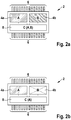
- Figure 2a Figure 3 shows an expanded embodiment of the present invention.
- the combination sensor module 2 again has at least two independent functional areas A, B or at least two sensor submodules 4a, b.
- Interface module 8 may provide a common energy supply, diagnosis, signal processing and / or interface function for sensor submodules 4a, b.
- the interface module 8 is designed such that it can provide the respective functionalities to one of the sensor submodules 4a, b without being impaired by the other sensor submodule. In other words, interface module 8 also independently provides the respective functionalities to sensor submodules 4a, b.
- the sensor submodules 4a, b may be connected to the interface module 8 in parallel or in a multiplex process, for example. Pins 6 in turn provide an option for contacting the combination sensor module 2 with the outside.
- Combination sensor module 2 according to Figure 2b corresponds essentially to the full module or combination sensor module 2 according to FIG Figure 2a , but analogous Figure 1c Area B or sensor submodule 4b is deactivated, not released or not functional, so that the entire combination sensor module 2 according to FIG Figure 2b essentially represents an "A module" and provides A functionality.
Landscapes
- Engineering & Computer Science (AREA)
- Transportation (AREA)
- Mechanical Engineering (AREA)
- Physics & Mathematics (AREA)
- General Physics & Mathematics (AREA)
- Gyroscopes (AREA)
- Testing Or Calibration Of Command Recording Devices (AREA)
- Air Bags (AREA)
Description
- Die vorliegende Patentanmeldung betrifft Sensorsysteme für ein Fahrzeug. Insbesondere betrifft die vorliegende Erfindung ein Kombinationssensorikmodul für ein Fahrzeug, ein Fahrzeug, insbesondere ein Automobil, aufweisend ein erfindungsgemäßes Kombinationssensorikmodul, sowie die Verwendung eines erfindungsgemäßen Kombinationssensorikmoduls in einem Fahrzeug.
- Moderne Fahrzeuge weisen gewöhnlich eine Vielzahl von fahrerunterstützten Systemen bzw. Fahrerassistenzsystemen und erweiterten Sicherheitseinrichtungen auf, beispielsweise Gurtstraffer oder Airbags. Um eine ordnungsgemäße Funktion dieser Assistenz- bzw. Sicherheitssysteme sicherzustellen, ist meist eine genaue Kenntnis der aktuellen am Fahrzeug vorherrschenden Bewegungssituation notwendig.
- Beispielsweise mögen Beschleunigungssensoren die Beschleunigung bzw. Abbremsung eines Fahrzeuges in eine bestimmte Richtung detektieren, während Drehratensensoren eine Verdrehung bzw. Rotation des Fahrzeugs um eine Achse detektieren mögen.
- Gewöhnlich wird hierzu ein dreidimensionales Koordinatensystem X,Y,Z verwendet, wobei X die Längsachse, Y die Querachse sowie Z die Hochachse des Fahrzeugs darstellt. Rollratensensoren wiederum mögen eine Drehung des Fahrzeugs um eine Achse X,Y,Z detektieren.
- Bekannt sind mikromechanische Kombimodule, in welchen meist eine Mehrzahl von, insbesondere drei, Sensoren mit zugehörigen Freiheitsgraden angeordnet ist. Dies mögen nicht zwingend ausschließlich drei Beschleunigungssensoren oder drei Rollratensensoren bzw. Drehsensor sein, vielmehr ist auch eine Kombination aus Beschleunigungs- und Drehsensor denkbar.
- Verschiedene Fahrerassistenz- bzw. Sicherheitssysteme mögen hierbei jeweils ganz individuelle Sensorkombinationen aufweisen.
- Beispielsweise mag für ein ESP-Modul ein Sensor mit drei Freiheitsgraden, somit allgemein ein 3D-Sensorelement, bereitgestellt sein, welches eine Beschleunigung in X- und Y-Richtung sowie eine Rotation um die Z-Achse detektieren mag. Für einen Rollover-Sensor wiederum mag ein 3D-Sensor eine Beschleunigung in Y- und Z-Achse sowie im Weiteren eine Rotation um die X-Achse messen.
- Derartige Sensormodule sind jedoch meist auf einen bestimmten Einsatzzweck ausgerichtet bzw. optimiert. Ein einfaches Austauschen ist somit meist nicht möglich.
- Die Druckschrift
US 5,297,052 A betrifft redundante Trägheitsreferenzsysteme für Flugzeuge. Die DruckschriftEP 1 795 902 A1 betrifft ein Verfahren und ein Gerät zur Beschleunigungsdetektion. Die DruckschriftUS 6,023,664 A beschreibt Sensoren für Fahrzeugkollisionen. - Ein Aspekt der vorliegenden Erfindung mag somit die Bereitstellung eines flexiblen Sensorikmoduls sein.
- Im Lichte dieses Aspekts wird ein Kombinationssensorikmodul für ein Fahrzeug, ein Fahrzeug, insbesondere ein Automobil, aufweisend ein erfindungsgemäßes Kombinationssensorikmodul sowie die Verwendung eines erfindungsgemäßen Kombinationssensorikmoduls in einem Fahrzeug gemäß der unabhängigen Ansprüche bereitgestellt. Bevorzugte Ausgestaltungen ergeben sich aus den abhängigen Ansprüchen.
- Die steigende Nachfrage an neuen Funktionen in einem Fahrzeug benötigt gleichzeitig zusätzliche Sensorkanäle. Jedoch werden in sicherheitsrelevanten Komponenten wie beispielsweise einem Airbagsteuergerät oder anderen Integrationsplattformen wie beispielsweise Fahrerassistenzsystemen immer mehr mikromechanische Sensoren verbaut.
- Eine solche Sensoranordnung mag bis maximal zu einer 6D-Sensierung ausgebildet sein. 6D mag in diesem Zusammenhang als ein Sensorelement mit sechs Freiheitsgraden gesehen werden, beispielsweise Beschleunigung und Verzögerung für X-, Y- und Z-Achse sowie weiterhin die Rotation um jeweils X-, Y- und Z-Achse. Allgemein mag somit eine "X"D-Sensierung als eine Sensierung mit "X" Freiheitsgraden bzw. "X" unabhängigen Sensorkanälen aufgefasst werden.
- Beispielsweise für Aktivlenkungsfunktionen mag sogar eine "6D+redundante" ESP-Sensorik denkbar sein.
- Die vorliegende Erfindung mag einerseits die Vereinigung von mindestens einer 5D-Sensorik, mithin Beschleunigung der X-, Y- und Z-Achsen sowie Rotation um X- und Z-Achse realisieren, vorteilhafterweise aber eine 6D-Sensorik, somit jeweils Beschleunigung und Rotation um jeder Y-, Y-, Z-Achse in einem gemeinsamen Sensormodul, enthalten.
- Das erfindungsgemäße Sensormodul mag hierbei derart optimiert sein, dass es auch bei defekten oder selektiven Schäden als Modul für bestimmte Funktionen weiterhin verwendbar ist. So mag beispielsweise ein erfindungsgemäßes 6D-Sensormodul, im Falle, dass ein Sensorfreiheitsgrad einen Defekt oder selektiven Schaden aufweist, zumindest als ein 5D-Sensormodul weiter verwendet werden.
- Im Rahmen der vorliegenden Erfindung wird somit die Vereinigung von 6D-Sensorik in einem gemeinsamen Sensorkombimodul angezeigt, hierbei aber insbesondere die funktionszugeordnete Anordnung, Ansteuerung, Diagnose und Testbarkeit der einzelnen Komponenten.
- Somit mag sich vorteilhaft nur ein Modul herstellen lassen, welches bei vollem Funktionsumfang als 6D-Sensormodul eingesetzt werden mag.
- Bei eingeschränkter Funktionalität, somit bei selektiven Defekten, beispielsweise in einem einzelnen Submodul oder einem Sensorpfad, mag das erfindungsgemäße Sensorkombimodul bzw. Kombinationssensorikmodul als ein solches Sensormodul verwendet werden, welches eine reduzierte Sensorik aufweist bzw. für eine bestimmten Einsatzzweck benötigt.
- So mag beispielsweise ein Initial als 6D-Sensormodul ausgebildetes Kombinationssensorikmodul im Falle eines selektiven Defektes eines Sensorpfades auch als ESP-Sensormodul, als Rollover-Sensormodul oder als Pitchraten-Sensormodul eingesetzt werden, je nachdem, welcher der fraglichen Sensorpfade defekt ist bzw. den selektiven Schaden aufweist.
- Vorteilhaft ergibt sich hierdurch die Reduktion der Modulvarianten, weiterhin eine Reduktion des Entwicklungsaufwandes sowie eine höhere Ausbeute durch Weiterverwendung von Teilausschuss, indem das entsprechende, teildefekte Modul als ein Sensormodul mit reduzierter Funktionalität verwendet werden mag.
- Auch mag gezielt eine kostengünstige Variante aus einem 6D-Sensormodul abgeleitet werden, indem zum Beispiel Prüfschritte für eine separate Funktion entfallen, eine Durchkontaktierung von im Modul angeordneter Elektronik nach außerhalb nicht erfolgt oder aber ein Teil des möglicherweise diskret aufgebauten, in sich vollständig abgeschlossenen Modulinnenlebens bzw. Modulkomponenteninnenlebens nicht bestückt wird. Insbesondere für den USamerikanischen Fahrzeugmarkt mag sich eine Kombination aus ESP- und Rollover-Sensorik als besonders vorteilhaft erweisen.
- Somit mögen sich mit einem 6D-Sensormodul auch neue Funktionen realisieren lassen, welche weitere Freiheitsgrade bzw. Sensorpfade erfordern, beispielsweise videobasierte Systeme, unterstützt durch die Nickrate des Fahrzeuges.
- Erfindungsgemäß weist das Kombinationssensorikmodul für ein Fahrzeug gemäß der vorliegenden Erfindung zumindest zwei Sensorsubmodule auf, welche in einem Kombinationssensorikmodul angeordnet und an die Elektronik des Fahrzeuges anschließbar sind, wobei die zumindest zwei Sensorsubmodule unabhängig voneinander betreibbar sind.
- Somit weist das erfindungsgemäße Kombinationssensorikmodul zumindest zwei vollständig unabhängige Bereiche bzw. Blöcke, mithin Sensorelemente oder applikationsspezifische integrierte Schaltungen (ASICs) auf, welche jeweils eine eigenständige Funktion bereitstellen. So mag jeder Bereich bzw. jedes Sensorsubmodul für sich genommen beispielsweise eine 1D-, 2D- oder 3D-Sensierung anbieten. Die Sensorsubmodule werden vollständig getrennt voneinander in einem gemeinsamen Baustein, dem Kombinationssensorikmodul angeordnet. Besonders bevorzugt sind die Sensorsubmodule sogar galvanisch voneinander getrennt angebracht.
- Die zumindest zwei Sensorsubmodule gemeinsam betrachten, beispielsweise jeweils ausgebildet als ein 3D-Sensormodul, bilden somit für das Kombinationssensorikmodul zusammengenommen ein 6D-Sensormodul.
- Ein modularer Aufbau des Kombinationssensorikmoduls mag hierbei besonders vorteilhaft sein. Beispielsweise mögen die einzelnen Sensorelemente bzw. Halbleiterelemente jedes Sensorsubmoduls übereinander angeordnet sein in einem sogenannten Stackingverfahren.
- Die einzelnen Sensorsubmodule funktionieren hierbei völlig unabhängig voneinander und mögen auch über eine getrennte/eigenständige Spannungsversorgung bzw. Energieversorgung verfügen, sowie beispielsweise über eine separate Diagnosefunktion.
- Somit mögen sich im Kombinationssensorikmodul zwei voneinander unabhängige Sensorsubmodule anordnen lassen, welche jedoch nach außerhalb des Kombinationssensorikmoduls als ein gemeinsames 6D-Sensormodul auftreten. Hierzu mag erfindungsgemäß auch eine gemeinsame Steuerung der Bereiche bzw. Funktionsblöcke oder Sensoren bzw. Sensorsubelemente erfolgen, z.B. über ein weiteres Modul wie beispielsweise ein gemeinsames Schnittstellenmodul, angeordnet im Kombinationssensorikmodul.
- Das Schnittstellenmodul mag hierbei eine (getrennte) Versorgung, einen Signaltransfer, eine Schnittstelle und Diagnose der Sensorsubmodule bereitstellen, welche zwar getrennt realisiert, jedoch zentral regelbar sein mögen. Das Schnittstellenmodul mag auch festlegen, ob ein Kombinationssensorikmodul beispielsweise als ein 6D-Sensorikmodul, als ein 3D-ESP-Sensorikmodul oder ein 3D-Rotationssensorikmodul eingesetzt wird bzw. sich nach außen dergestalt verhält.
- So mag beispielsweise im Falle, dass beide Sensorsubmodule einwandfrei funktionieren, das Kombinationssensorikmodul als ein 6D-Sensorikmodul eingesetzt werden, während im Falle, dass ein Sensorsubmodul einen Defekt aufweist, das Kombinationssensorikmodul zumindest noch als ein 3D-ESP- oder 3D-Rotationssensorikmodul eingesetzt werden mag.
- Ein Defekt oder ein selektiver Schaden mag jedoch auch vorliegen, wenn eine geforderte bzw. vorgegebene Messgenauigkeit eines Sensormodules nicht eingehalten werden kann.
- In diesem Fall mag ein Sensorsubmodul, welches die vorgegebene Messgenauigkeit einhält, als ein Automotive-Submodul verwendet werden, welches sicherheitsrelevante Funktionen im Fahrzeug bereitstellt bzw. überwacht, während ein Sensorsubmodul, welches die vorgegebene Messgenauigkeit nicht einhalten mag, beispielsweise als ein Teil einer Consumer-Elektronik im Fahrzeug verwendet werden mag, beispielsweise für Bildstabilisierung von Kameras, Anbindung eines Mobiltelefons an die Autoelektronik, Audio- und/oder Video-Wiedergabe.
- Das Kombinationssensorikmodul mag, insbesondere unter Verwendung des Schnittstellenmoduls, an ein Ethernet-Bussystem oder Fahrzeug-Bussystem, beispielsweise CAN-Bus oder FlexRay, angeschlossen sein.
- Ausführungsbeispiele der Erfindung sind in den Zeichnungen dargestellt und in der nachfolgenden Beschreibung näher erläutert.
- Es zeigen
- Figuren 1a-c
- eine schematische Darstellung eines exemplarischen Ausführungsbeispiels eines Kombinationssensorikmoduls gemäß der vorliegenden Erfindung; und
- Figuren 2a,b
- eine schematische Darstellung einer weiteren exemplarischen Ausgestaltung der vorliegenden Erfindung.
-
Figuren 1a-c zeigen eine schematische Darstellung eines exemplarischen Ausführungsbeispiels eines Kombinationssensorikmoduls gemäß der vorliegenden Erfindung. -
Figur 1a zeigt ein erfindungsgemäßes Kombinationssensorikmodul 2, aufweisend zwei Sensorsubmodule 4a, b, bezeichnet mit den Buchstaben A und B. Die beiden Sensorsubmodule 4a, b sind in einem gemeinsamen Gehäuse des Kombinationssensorikmoduls 2 angeordnet, jedoch vollständig getrennt eingerichtet. - Jeder der beiden Bereiche bzw. jedes der Sensorsubmodule 4a, b ist eingerichtet, unterschiedliche Funktionen, insbesondere getrennt vom jeweils anderen Sensorsubmodul 4b,a bereitzustellen.
- So mag beispielsweise Sensorsubmodul 4a als ESP-Sensormodul und Sensorsubmodul 4b als Rollover-Sensormodul ausgebildet sein. Für jede dieser unterschiedlichen Modulfunktionen mögen beispielsweise 3D-Sensierung benötigt werden, welche zusammen eine 6D-Sensierung ergeben mögen. Die Bereiche A und B der Sensorsubmodule 4a, b sind jeweils an unterschiedlichen Pins 6 aus dem Gehäuse bzw. aus dem Kombinationssensorikmodul 2 herausgeführt.
- Das Kombinationssensorikmodul 2 gemäß
Figur 1a ist hierbei in allen Bereichen A und B einsatzbereit und entspricht damit mindestens einem 5D- bzw. 6D-Modul, gesehen über beide Bereiche A und B. -
Figur 1b stellt ein Kombinationssensorikmodul 2 dar gemäßFigur 1a , hierbei ist jedoch angenommen, dass Bereich A bzw. Sensorsubmodul 4a in einem nicht funktionsfähigen Zustand ist. Bereich A bzw. Sensorsubmodul 4a mag hierbei entweder fehlerhaft sein, zum Beispiel aufgrund eines Defektes während der Herstellung, oder auch nach Vorgabe nicht getestet bzw. nicht freigegeben worden sein. - Produktionstechnisch mag sich das Kombinationssensorikmodul 2 gemäß
Figur 1b von einem Vollmodul 2 gemäßFigur 1 a ableiten lassen, ist jedoch nur als "B-Modul" mit der Funktionalität des Bereichs B bzw. des Sensorsubmoduls 4b einsetzbar. Die zum Bereich A bzw. Sensorsubmodul 4a gehörenden Pins 6 mögen entweder nicht belegt, nicht durchkontaktiert oder auch gleichfalls überhaupt nicht vorhanden bzw. nach außen geführt sein. - Kombinationssensorikmodul 2 gemäß
Figur 1c ist wiederum vom Kombinationssensorikmodul 2 als Vollmodul gemäßFigur 1 a abgeleitet, hierbei ist jedoch nur der Bereich A bzw. das Sensorsubmodul 4a funktionsfähig. Somit stellt Kombinationssensorikmodul 2 gemäßFigur 1c im Wesentlichen ein "A-Modul" mit A-Funktionalität dar. - Weiter Bezug nehmend auf
Figuren 2a, b ist eine schematische Darstellung einer weiteren exemplarischen Ausgestaltung der vorliegenden Erfindung dargestellt. -
Figur 2a zeigt eine erweiterte Ausführung der vorliegenden Erfindung. Das Kombinationssensorikmodul 2 besitzt wieder zumindest zwei unabhängige funktionale Bereiche A, B bzw. zumindest zwei Sensorsubmodule 4a, b. - Ein weiteres Schnittstellenmodul 8 bzw. ein Bereich C ist im Kombinationssensorikmodul 2 vorgesehen, welches gemeinsame Funktionen für die Sensorsubmodule 4a,b bereitstellt. So mag Schnittstellenmodul 8 eine gemeinsame Energieversorgung, Diagnose, Signalaufbereitung und/oder Schnittstellenfunktion für Sensorsubmodule 4a,b bereitstellen.
- Hierbei ist Schnittstellenmodul 8 jedoch derart ausgebildet, dass es die jeweiligen Funktionalitäten an eines der Sensorsubmodule 4a,b bereitstellen kann, ohne durch das andere Sensorsubmodul beeinträchtigt zu werden. In anderen Worten stellt Schnittstellenmodul 8 gleichfalls unabhängig die jeweiligen Funktionalitäten den Sensorsubmodulen 4a, b bereit.
- Die Sensorsubmodule 4a, b mögen beispielsweise parallel oder in einem Multiplexverfahren an das Schnittstellenmodul 8 angebunden sein. Pins 6 stellen wiederum eine Kontaktierungsmöglichkeit des Kombinationssensorikmoduls 2 nach außen bereit.
- In
Figur 2a dargestellt ist das Kombinationssensorikmodul 2 mit vollem Funktionsumfang, bestehend aus zwei voll funktionsfähigen Sensorsubmodulen 4a, b. - Kombinationssensorikmodul 2 gemäß
Figur 2b entspricht im Wesentlichen dem Vollmodul bzw. Kombinationssensorikmodul 2 gemäßFigur 2a , wobei jedoch analogFigur 1c Bereich B bzw. Sensorsubmodul 4b deaktiviert, nicht freigegeben bzw. nicht funktional ist, so dass das gesamte Kombinationssensorikmodul 2 gemäßFigur 2b im Wesentlichen ein "A-Modul" darstellt und A-Funktionalität bereitstellt.
Claims (10)
- Kombinationssensorikmodul (2) für ein Fahrzeug, aufweisend
zumindest ein erstes Sensorsubmodul (4a) und ein zweites Sensorsubmodul (4b), beide Sensorsubmodule (4a, b) angeordnet im Kombinationssensorikmodul (2) und anschließbar an die Elektronik des Fahrzeuges,
dadurch gekennzeichnet, dass
die zumindest zwei Sensorsubmodule (4a, b) unabhängig voreinander betreibbar sind,
wobei das Kombinationssensorikmodul (2) dazu eingerichtet ist,
bei selektiven Produktionsschäden des ersten Sensorsubmoduls (4a) nur mit der Funktionalität des zweiten Sensorsubmoduls (4b) betreibbar zu sein,
bei selektiven Produktionsschäden des zweiten Sensorsubmoduls (4b) nur mit der Funktionalität des ersten Sensorsubmoduls (4a) betreibbar zu sein, und
bei keinen Produktionsschäden mit der Funktionalität der beiden Sensorsubmodule (4a, b) betreibbar zu sein. - Kombinationssensorikmodul gemäß dem vorhergehenden Anspruch, wobei unabhängig betreibbar bedeutet, dass eines der zumindest zwei Sensorsubmodule eingerichtet ist bei Defekt oder Ausfall des Weiteren der zumindest zwei Sensorsubmodule weiterhin betreibbar zu sein.
- Kombinationssensorikmodul gemäß zumindest einem der vorhergehenden Ansprüche, weiterhin aufweisend
ein Schnittstellenmodul (8),
wobei die zumindest zwei Sensorsubmodule (4a, b) mit dem Schnittstellenmodul (8) kommunikativ gekoppelt sind; und
wobei das Schnittstellenmodul (8) zumindest eine der Funktionen aus der Gruppe bestehend aus Energieversorgung, Diagnose, Signalaufbereitung und Schnittstellenfunktionalität für die zumindest zwei Sensorsubmodule (4a, b) bereitstellt. - Kombinationssensorikmodul gemäß zumindest einem der vorhergehenden Ansprüche,
wobei jedes der zumindest zwei Sensorsubmodule (4a, b) als ein 3D-Sensormodul ausgebildet ist, und/oder
wobei die zumindest zwei Sensorsubmodule (4a, b) zusammen als ein 6D-Sensormodul ausgebildet sind. - Kombinationssensorikmodul gemäß zumindest einem der vorhergehenden Ansprüche,
wobei jedes der zumindest zwei Sensorsubmodule (4a, b) ausgebildet ist als ein Sensormodul aus der Gruppe bestehend aus Rollover-Sensormodul, Pitchraten-Sensormodul, ESP-Sensormodul, 3D Drehratenmodul und triaxialer Beschleunigungssensor. - Kombinationssensorikmodul gemäß zumindest einem der vorhergehenden Ansprüche,
wobei die zumindest zwei Sensorsubmodule (4a, b) galvanisch voneinander getrennt ausgebildet und im Kombinationssensorikmodul (2) angeordnet sind. - Kombinationssensorikmodul gemäß zumindest einem der vorhergehenden Ansprüche,
wobei das Kombinationssensorikmodul (2) als 6D-Sensormodul betreibbar ist, falls die zumindest zwei Sensorsubmodule (4a, b) keinen Defekt aufweisen; und
wobei das Kombinationssensorikmodul (2) zumindest als 3D-Sensormodul betreibbar ist, falls eines der zumindest zwei Sensorsubmodule (4a, b) einen Defekt aufweist. - Fahrzeug, insbesondere Automobil, aufweisend ein
Kombinationssensorikmodul (2) gemäß zumindest einem der vorhergehenden Ansprüche. - Verwendung eines Kombinationssensorikmodul (2) gemäß zumindest einem der vorhergehenden Ansprüche in einem Fahrzeug.
- Verwendung gemäß Anspruch 9,
wobei das Kombinationssensorikmodul (2) als 6D-Sensormodul betreibbar ist, falls die zumindest zwei Sensorsubmodule (4a, b) keinen Defekt aufweisen; und
wobei das Kombinationssensorikmodul (2) zumindest als 3D-Sensormodul betreibbar ist, falls eines der zumindest zwei Sensorsubmodule (4a, b) einen Defekt aufweist.
Applications Claiming Priority (2)
| Application Number | Priority Date | Filing Date | Title |
|---|---|---|---|
| DE102011004333A DE102011004333A1 (de) | 2011-02-17 | 2011-02-17 | Flexibles Kombinationssensorikmodul für ein Fahrzeug |
| PCT/EP2011/073807 WO2012110150A1 (de) | 2011-02-17 | 2011-12-22 | Flexibles kombinationssensorikmodul für ein fahrzeug |
Publications (2)
| Publication Number | Publication Date |
|---|---|
| EP2675668A1 EP2675668A1 (de) | 2013-12-25 |
| EP2675668B1 true EP2675668B1 (de) | 2021-07-28 |
Family
ID=45491554
Family Applications (1)
| Application Number | Title | Priority Date | Filing Date |
|---|---|---|---|
| EP11808643.8A Active EP2675668B1 (de) | 2011-02-17 | 2011-12-22 | Flexibles kombinationssensorikmodul für ein fahrzeug |
Country Status (6)
| Country | Link |
|---|---|
| US (1) | US9189894B2 (de) |
| EP (1) | EP2675668B1 (de) |
| JP (1) | JP2014512513A (de) |
| CN (1) | CN103347750B (de) |
| DE (1) | DE102011004333A1 (de) |
| WO (1) | WO2012110150A1 (de) |
Families Citing this family (2)
| Publication number | Priority date | Publication date | Assignee | Title |
|---|---|---|---|---|
| DE102015221454A1 (de) * | 2015-11-03 | 2017-05-04 | Conti Temic Microelectronic Gmbh | Sensormodul für ein Kraftfahrzeug |
| CN111231986A (zh) * | 2020-03-28 | 2020-06-05 | 芜湖伯特利汽车安全系统股份有限公司 | 用于机动车的冗余轮速检测装置及其控制方法 |
Family Cites Families (14)
| Publication number | Priority date | Publication date | Assignee | Title |
|---|---|---|---|---|
| DE3634023A1 (de) * | 1986-10-07 | 1988-04-21 | Bodenseewerk Geraetetech | Integriertes, redundantes referenzsystem fuer die flugregelung und zur erzeugung von kurs- und lageinformationen |
| US5274894A (en) * | 1989-10-04 | 1994-01-04 | Zellweger Uster Ag | Machine for the automatic drawing-in of warp threads |
| US5297052A (en) * | 1989-10-16 | 1994-03-22 | The Boeing Company | Integrated fault-tolerant air data inertial reference system |
| US5201380A (en) * | 1991-07-10 | 1993-04-13 | Trw Inc. | Phased redundant sensor steering control |
| US6023664A (en) * | 1996-10-16 | 2000-02-08 | Automotive Systems Laboratory, Inc. | Vehicle crash sensing system |
| JP2006090919A (ja) * | 2004-09-27 | 2006-04-06 | Yokohama Rubber Co Ltd:The | 加速度検出方法及びその装置、加速度センサモジュール並びにタイヤ |
| DE102005016009A1 (de) | 2005-04-07 | 2006-10-12 | Robert Bosch Gmbh | Verfahren und Vorrichtung zur Stabilisierung eines Fahrzeugs nach einer Kollision |
| SE528484C2 (sv) | 2005-04-11 | 2006-11-28 | Advanced Inertial Measurement | Kontrollsystem för fordon |
| JP2008021732A (ja) | 2006-07-11 | 2008-01-31 | Tokyo Electron Ltd | 圧力異常原因判定方法,圧力異常原因判定システム,真空処理装置,記録媒体 |
| JP5319122B2 (ja) * | 2008-01-21 | 2013-10-16 | 日立オートモティブシステムズ株式会社 | 慣性センサ |
| JP2009204459A (ja) * | 2008-02-28 | 2009-09-10 | Denso Corp | 車両用慣性力センサおよび車両の傾斜検出方法 |
| JP2010190701A (ja) * | 2009-02-18 | 2010-09-02 | Panasonic Electric Works Co Ltd | 圧力センサの実装構造 |
| JP5444199B2 (ja) * | 2010-12-06 | 2014-03-19 | 日立オートモティブシステムズ株式会社 | 複合センサ |
| US9068797B2 (en) * | 2011-06-20 | 2015-06-30 | Bae Systems Information And Electronic Systems Integration Inc. | Dynamic real-time boresighting system and method |
-
2011
- 2011-02-17 DE DE102011004333A patent/DE102011004333A1/de not_active Ceased
- 2011-12-22 JP JP2013552863A patent/JP2014512513A/ja active Pending
- 2011-12-22 US US14/000,063 patent/US9189894B2/en active Active
- 2011-12-22 EP EP11808643.8A patent/EP2675668B1/de active Active
- 2011-12-22 WO PCT/EP2011/073807 patent/WO2012110150A1/de not_active Ceased
- 2011-12-22 CN CN201180067779.3A patent/CN103347750B/zh active Active
Non-Patent Citations (1)
| Title |
|---|
| None * |
Also Published As
| Publication number | Publication date |
|---|---|
| CN103347750A (zh) | 2013-10-09 |
| CN103347750B (zh) | 2016-11-09 |
| US20140081477A1 (en) | 2014-03-20 |
| WO2012110150A1 (de) | 2012-08-23 |
| JP2014512513A (ja) | 2014-05-22 |
| EP2675668A1 (de) | 2013-12-25 |
| US9189894B2 (en) | 2015-11-17 |
| DE102011004333A1 (de) | 2012-08-23 |
Similar Documents
| Publication | Publication Date | Title |
|---|---|---|
| DE19813957C2 (de) | Insassenschutzsystem mit einer Zentraleinheit, Sensoren und mehreren mittels eines BUS-Systems kommunikationsfähig verbundenen Steuermodulen zur Auslösung von Insassenschutzeinrichtungen | |
| EP1855924A1 (de) | Elektronisches kraftfahrzeugbremsensteuergerät | |
| DE102008040145A1 (de) | Vorrichtung zur Ansteuerung aller Airbags für ein Fahrzeug, Steuergerät zur Bildung eines Ansteuersignals für alle Airbags für ein Fahrzeug und ein System aus der Vorrichtung und dem Steuergerät | |
| EP2146873B1 (de) | Vorrichtung und verfahren zur ansteuerung von personenschutzmitteln | |
| DE112013004598B4 (de) | Airbag-Sensormodul und Fahrzeugkarosserie mit einem integrierten Airbag-Sensormodul | |
| EP3983274B1 (de) | Einrichtung und verfahren zum ausführen zumindest einer fahrzeugfunktion für ein fahrzeug | |
| DE102021106276A1 (de) | Betriebsverfahren für ein rückhaltesystem und rückhaltesystem für ein fahrzeug mit abnehmbaren türen | |
| DE102011004333A1 (de) | Flexibles Kombinationssensorikmodul für ein Fahrzeug | |
| EP1970262B1 (de) | Steuergerät und Verfahren zur Ansteuerung von Personenschutzmitteln | |
| DE102006036861B4 (de) | Passagier-Schutzsystem | |
| DE10359875A1 (de) | Digitales Netzwerk für Kraftfahrzeuge | |
| DE102009027402B4 (de) | Verfahren und Steuergerät zur Ansteuerung von Insassenschutzmitteln eines Fahrzeugs bei einer Mehrfachkollision | |
| DE102004008616A1 (de) | Verfahren und Vorrichtung zur Erfassung und Verarbeitung des Luftdruckes in einem Fahrzeug | |
| DE102004040322A1 (de) | Dezentrale, intelligente Steuereinheit für ein Rückhaltesystem in einem Fahrzeug | |
| DE102006049121B3 (de) | Unfallerkennungsvorrichtung mit redundant angeordneten Beschleunigungssensoren zur Frontalaufprallerkennung in einem Kraftfahrzeug | |
| DE102013102425A1 (de) | Kollisionsfeststellungsvorrichtung für ein Fahrzeug | |
| DE202014007799U1 (de) | Sicherheitsgurtsystem, Überwachungsvorrichtung und Kraftfahrzeug mit Sicherheitsgurtsystem | |
| EP4363277B1 (de) | Steuergerät für ein personenschutzsystem | |
| DE102008003776B4 (de) | Steuergerät | |
| DE102005063128A1 (de) | Drucksensorvorrichtung zur Erzeugung von Ansteuerungssignalen für Fahrzeugsicherheitssysteme und Motorsteuerungssysteme | |
| DE10153052A1 (de) | Verteilte Steuerungsarchitektur für eine Insassenrückhalteanordnung | |
| DE19757137A1 (de) | Verfahren zum Auslösen eines Insassenschutzsystems für Kraftfahrzeuge sowie ein Insassenschutzsystem für Kraftfahrzeuge | |
| DE102006030563A1 (de) | Sensoreinheit und zugehöriges Schutzsystem für ein Fahrzeug | |
| DE102007028985B4 (de) | Steuervorrichtung für kombinierte Kfz-Sicherheitssysteme | |
| EP2143593B1 (de) | Rückhaltemittelsteuerung für ein Steuergerät |
Legal Events
| Date | Code | Title | Description |
|---|---|---|---|
| PUAI | Public reference made under article 153(3) epc to a published international application that has entered the european phase |
Free format text: ORIGINAL CODE: 0009012 |
|
| 17P | Request for examination filed |
Effective date: 20130917 |
|
| AK | Designated contracting states |
Kind code of ref document: A1 Designated state(s): AL AT BE BG CH CY CZ DE DK EE ES FI FR GB GR HR HU IE IS IT LI LT LU LV MC MK MT NL NO PL PT RO RS SE SI SK SM TR |
|
| DAX | Request for extension of the european patent (deleted) | ||
| RAP1 | Party data changed (applicant data changed or rights of an application transferred) |
Owner name: ROBERT BOSCH GMBH |
|
| STAA | Information on the status of an ep patent application or granted ep patent |
Free format text: STATUS: EXAMINATION IS IN PROGRESS |
|
| 17Q | First examination report despatched |
Effective date: 20200512 |
|
| GRAP | Despatch of communication of intention to grant a patent |
Free format text: ORIGINAL CODE: EPIDOSNIGR1 |
|
| STAA | Information on the status of an ep patent application or granted ep patent |
Free format text: STATUS: GRANT OF PATENT IS INTENDED |
|
| INTG | Intention to grant announced |
Effective date: 20210216 |
|
| GRAS | Grant fee paid |
Free format text: ORIGINAL CODE: EPIDOSNIGR3 |
|
| GRAA | (expected) grant |
Free format text: ORIGINAL CODE: 0009210 |
|
| STAA | Information on the status of an ep patent application or granted ep patent |
Free format text: STATUS: THE PATENT HAS BEEN GRANTED |
|
| AK | Designated contracting states |
Kind code of ref document: B1 Designated state(s): AL AT BE BG CH CY CZ DE DK EE ES FI FR GB GR HR HU IE IS IT LI LT LU LV MC MK MT NL NO PL PT RO RS SE SI SK SM TR |
|
| REG | Reference to a national code |
Ref country code: GB Ref legal event code: FG4D Free format text: NOT ENGLISH |
|
| REG | Reference to a national code |
Ref country code: CH Ref legal event code: EP |
|
| REG | Reference to a national code |
Ref country code: DE Ref legal event code: R096 Ref document number: 502011017184 Country of ref document: DE |
|
| REG | Reference to a national code |
Ref country code: AT Ref legal event code: REF Ref document number: 1414474 Country of ref document: AT Kind code of ref document: T Effective date: 20210815 |
|
| REG | Reference to a national code |
Ref country code: IE Ref legal event code: FG4D Free format text: LANGUAGE OF EP DOCUMENT: GERMAN |
|
| REG | Reference to a national code |
Ref country code: LT Ref legal event code: MG9D |
|
| REG | Reference to a national code |
Ref country code: NL Ref legal event code: MP Effective date: 20210728 |
|
| PG25 | Lapsed in a contracting state [announced via postgrant information from national office to epo] |
Ref country code: HR Free format text: LAPSE BECAUSE OF FAILURE TO SUBMIT A TRANSLATION OF THE DESCRIPTION OR TO PAY THE FEE WITHIN THE PRESCRIBED TIME-LIMIT Effective date: 20210728 Ref country code: SE Free format text: LAPSE BECAUSE OF FAILURE TO SUBMIT A TRANSLATION OF THE DESCRIPTION OR TO PAY THE FEE WITHIN THE PRESCRIBED TIME-LIMIT Effective date: 20210728 Ref country code: BG Free format text: LAPSE BECAUSE OF FAILURE TO SUBMIT A TRANSLATION OF THE DESCRIPTION OR TO PAY THE FEE WITHIN THE PRESCRIBED TIME-LIMIT Effective date: 20211028 Ref country code: LT Free format text: LAPSE BECAUSE OF FAILURE TO SUBMIT A TRANSLATION OF THE DESCRIPTION OR TO PAY THE FEE WITHIN THE PRESCRIBED TIME-LIMIT Effective date: 20210728 Ref country code: NO Free format text: LAPSE BECAUSE OF FAILURE TO SUBMIT A TRANSLATION OF THE DESCRIPTION OR TO PAY THE FEE WITHIN THE PRESCRIBED TIME-LIMIT Effective date: 20211028 Ref country code: NL Free format text: LAPSE BECAUSE OF FAILURE TO SUBMIT A TRANSLATION OF THE DESCRIPTION OR TO PAY THE FEE WITHIN THE PRESCRIBED TIME-LIMIT Effective date: 20210728 Ref country code: PT Free format text: LAPSE BECAUSE OF FAILURE TO SUBMIT A TRANSLATION OF THE DESCRIPTION OR TO PAY THE FEE WITHIN THE PRESCRIBED TIME-LIMIT Effective date: 20211129 Ref country code: RS Free format text: LAPSE BECAUSE OF FAILURE TO SUBMIT A TRANSLATION OF THE DESCRIPTION OR TO PAY THE FEE WITHIN THE PRESCRIBED TIME-LIMIT Effective date: 20210728 Ref country code: ES Free format text: LAPSE BECAUSE OF FAILURE TO SUBMIT A TRANSLATION OF THE DESCRIPTION OR TO PAY THE FEE WITHIN THE PRESCRIBED TIME-LIMIT Effective date: 20210728 Ref country code: FI Free format text: LAPSE BECAUSE OF FAILURE TO SUBMIT A TRANSLATION OF THE DESCRIPTION OR TO PAY THE FEE WITHIN THE PRESCRIBED TIME-LIMIT Effective date: 20210728 |
|
| PG25 | Lapsed in a contracting state [announced via postgrant information from national office to epo] |
Ref country code: PL Free format text: LAPSE BECAUSE OF FAILURE TO SUBMIT A TRANSLATION OF THE DESCRIPTION OR TO PAY THE FEE WITHIN THE PRESCRIBED TIME-LIMIT Effective date: 20210728 Ref country code: LV Free format text: LAPSE BECAUSE OF FAILURE TO SUBMIT A TRANSLATION OF THE DESCRIPTION OR TO PAY THE FEE WITHIN THE PRESCRIBED TIME-LIMIT Effective date: 20210728 Ref country code: GR Free format text: LAPSE BECAUSE OF FAILURE TO SUBMIT A TRANSLATION OF THE DESCRIPTION OR TO PAY THE FEE WITHIN THE PRESCRIBED TIME-LIMIT Effective date: 20211029 |
|
| PG25 | Lapsed in a contracting state [announced via postgrant information from national office to epo] |
Ref country code: DK Free format text: LAPSE BECAUSE OF FAILURE TO SUBMIT A TRANSLATION OF THE DESCRIPTION OR TO PAY THE FEE WITHIN THE PRESCRIBED TIME-LIMIT Effective date: 20210728 |
|
| REG | Reference to a national code |
Ref country code: DE Ref legal event code: R097 Ref document number: 502011017184 Country of ref document: DE |
|
| PG25 | Lapsed in a contracting state [announced via postgrant information from national office to epo] |
Ref country code: SM Free format text: LAPSE BECAUSE OF FAILURE TO SUBMIT A TRANSLATION OF THE DESCRIPTION OR TO PAY THE FEE WITHIN THE PRESCRIBED TIME-LIMIT Effective date: 20210728 Ref country code: SK Free format text: LAPSE BECAUSE OF FAILURE TO SUBMIT A TRANSLATION OF THE DESCRIPTION OR TO PAY THE FEE WITHIN THE PRESCRIBED TIME-LIMIT Effective date: 20210728 Ref country code: RO Free format text: LAPSE BECAUSE OF FAILURE TO SUBMIT A TRANSLATION OF THE DESCRIPTION OR TO PAY THE FEE WITHIN THE PRESCRIBED TIME-LIMIT Effective date: 20210728 Ref country code: EE Free format text: LAPSE BECAUSE OF FAILURE TO SUBMIT A TRANSLATION OF THE DESCRIPTION OR TO PAY THE FEE WITHIN THE PRESCRIBED TIME-LIMIT Effective date: 20210728 Ref country code: CZ Free format text: LAPSE BECAUSE OF FAILURE TO SUBMIT A TRANSLATION OF THE DESCRIPTION OR TO PAY THE FEE WITHIN THE PRESCRIBED TIME-LIMIT Effective date: 20210728 Ref country code: AL Free format text: LAPSE BECAUSE OF FAILURE TO SUBMIT A TRANSLATION OF THE DESCRIPTION OR TO PAY THE FEE WITHIN THE PRESCRIBED TIME-LIMIT Effective date: 20210728 |
|
| PLBE | No opposition filed within time limit |
Free format text: ORIGINAL CODE: 0009261 |
|
| STAA | Information on the status of an ep patent application or granted ep patent |
Free format text: STATUS: NO OPPOSITION FILED WITHIN TIME LIMIT |
|
| 26N | No opposition filed |
Effective date: 20220429 |
|
| PG25 | Lapsed in a contracting state [announced via postgrant information from national office to epo] |
Ref country code: MC Free format text: LAPSE BECAUSE OF FAILURE TO SUBMIT A TRANSLATION OF THE DESCRIPTION OR TO PAY THE FEE WITHIN THE PRESCRIBED TIME-LIMIT Effective date: 20210728 Ref country code: IT Free format text: LAPSE BECAUSE OF FAILURE TO SUBMIT A TRANSLATION OF THE DESCRIPTION OR TO PAY THE FEE WITHIN THE PRESCRIBED TIME-LIMIT Effective date: 20210728 |
|
| REG | Reference to a national code |
Ref country code: CH Ref legal event code: PL |
|
| REG | Reference to a national code |
Ref country code: BE Ref legal event code: MM Effective date: 20211231 |
|
| PG25 | Lapsed in a contracting state [announced via postgrant information from national office to epo] |
Ref country code: LU Free format text: LAPSE BECAUSE OF NON-PAYMENT OF DUE FEES Effective date: 20211222 Ref country code: IE Free format text: LAPSE BECAUSE OF NON-PAYMENT OF DUE FEES Effective date: 20211222 |
|
| PG25 | Lapsed in a contracting state [announced via postgrant information from national office to epo] |
Ref country code: BE Free format text: LAPSE BECAUSE OF NON-PAYMENT OF DUE FEES Effective date: 20211231 |
|
| PG25 | Lapsed in a contracting state [announced via postgrant information from national office to epo] |
Ref country code: LI Free format text: LAPSE BECAUSE OF NON-PAYMENT OF DUE FEES Effective date: 20211231 Ref country code: CH Free format text: LAPSE BECAUSE OF NON-PAYMENT OF DUE FEES Effective date: 20211231 |
|
| REG | Reference to a national code |
Ref country code: AT Ref legal event code: MM01 Ref document number: 1414474 Country of ref document: AT Kind code of ref document: T Effective date: 20211222 |
|
| PG25 | Lapsed in a contracting state [announced via postgrant information from national office to epo] |
Ref country code: AT Free format text: LAPSE BECAUSE OF NON-PAYMENT OF DUE FEES Effective date: 20211222 |
|
| PG25 | Lapsed in a contracting state [announced via postgrant information from national office to epo] |
Ref country code: HU Free format text: LAPSE BECAUSE OF FAILURE TO SUBMIT A TRANSLATION OF THE DESCRIPTION OR TO PAY THE FEE WITHIN THE PRESCRIBED TIME-LIMIT; INVALID AB INITIO Effective date: 20111222 Ref country code: CY Free format text: LAPSE BECAUSE OF FAILURE TO SUBMIT A TRANSLATION OF THE DESCRIPTION OR TO PAY THE FEE WITHIN THE PRESCRIBED TIME-LIMIT Effective date: 20210728 |
|
| PG25 | Lapsed in a contracting state [announced via postgrant information from national office to epo] |
Ref country code: MK Free format text: LAPSE BECAUSE OF FAILURE TO SUBMIT A TRANSLATION OF THE DESCRIPTION OR TO PAY THE FEE WITHIN THE PRESCRIBED TIME-LIMIT Effective date: 20210728 |
|
| PG25 | Lapsed in a contracting state [announced via postgrant information from national office to epo] |
Ref country code: TR Free format text: LAPSE BECAUSE OF FAILURE TO SUBMIT A TRANSLATION OF THE DESCRIPTION OR TO PAY THE FEE WITHIN THE PRESCRIBED TIME-LIMIT Effective date: 20210728 |
|
| PG25 | Lapsed in a contracting state [announced via postgrant information from national office to epo] |
Ref country code: MT Free format text: LAPSE BECAUSE OF FAILURE TO SUBMIT A TRANSLATION OF THE DESCRIPTION OR TO PAY THE FEE WITHIN THE PRESCRIBED TIME-LIMIT Effective date: 20210728 |
|
| PGFP | Annual fee paid to national office [announced via postgrant information from national office to epo] |
Ref country code: GB Payment date: 20251218 Year of fee payment: 15 |
|
| PGFP | Annual fee paid to national office [announced via postgrant information from national office to epo] |
Ref country code: FR Payment date: 20251218 Year of fee payment: 15 |
|
| PGFP | Annual fee paid to national office [announced via postgrant information from national office to epo] |
Ref country code: DE Payment date: 20260223 Year of fee payment: 15 |